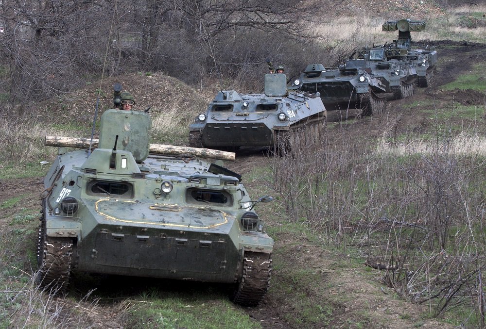
MT-LB

The MT-LB was developed by KhTZ (Kharkov Tractor Plant) as a successor to the AT-P and AT-L prime movers. It is worth noting that the KhTZ factory is distinct from the more famous KhPZ (Kharkov Locomotive Plant), responsible for the T-34, T-54, T-64, and so on. The MT-LB was intended for a tactical tractor-transporter role, acting as a prime mover for both anti-tank guns and artillery pieces. At the time it entered service, the most modern anti-tank gun available in the USSR was the 100mm T-12. Thanks to its lightweight design, this gun could be dependably towed by even the AT-P (Артиллерийский Тягач - Полубронированный, or Artillery Tractor - Semi-armoured), but even so, the size and payload capacity of the AT-P was too limited to effectively serve as the prime mover for the T-12, and the semi-armoured prime mover concept was becoming questionable due to the proliferation of tactical nuclear weapons.
In contrast to the AT-P, the AT-L (Артиллерийский Тягач - Лёгкий, or Artillery Tractor - Light) was ostensibly providing untroubled service as a prime mover for heavy mortars and 122mm howitzers, but after some years of use in the army, hull cracking was observed due to vibrations from the suspension. On top of this, it was found in 1959 that its capacity for modernization was limited, as the level of mobility could not be feasibly improved by fitting a larger, more powerful engine because it led to the hull becoming excessively nose-heavy.
With the AT-P and AT-L not performing to the desired level and lacking future prospects, the army found a need for a replacement for both vehicles. This was despite the fact that both vehicles had only recently entered service; the AT-P in 1954, and the AT-L in 1952. Given the need to fulfill the roles of two different prime movers, the successor vehicle in development at KhTZ was aptly named the MT-L (Многоцелевой Тягач - Легкий, or Multi-purpose Tractor - Light).

When the MT-L was still in development, the perceived need for a basic level of protection for a combat prime mover led to the Army's insistence on a fully enclosed armoured hull complete with NBC protection for the new vehicle, resulting in the creation of the MT-LB. With the addition of armour, the weight of the vehicle rose, although it was kept under control by the lowering of the vehicle silhouette. Compared with the 8.5-ton curb weight of the MT-L, the 9.7-ton curb weight of the MT-LB indicates that the weight gain was relatively limited despite the retention of almost all preexisting features; only the winch of the MT-L was removed in the MT-LB.
Testing was carried out in the regions customarily used by the Soviet military, including the Arctic and Turkmenistan for cold and hot climate trials. On 25 December 1964, the development cycle of the MT-LB concluded and it was accepted into service in the Soviet Army alongside the MT-L. KhTZ began the process of retooling its AT-L production line to switch to MT-LB production, which was handled with difficulty, as the assembly line for AT-Ls had been maintaining an average production rate of 5 vehicles a day to meet demand. Under such circumstances, the idea of producing both the MT-L and MT-LB simultaneously only complicated matters. As there was a considerable difference in the hulls of the two vehicles, it was decided that the capacity of the KhTZ plant was to be concentrated into a single production line dedicated solely to the MT-LB, and the technical documentation for the MT-L was transferred to the Semipalatinsk Machine-Building Plant, where the technology was used to improve the plant's products. With this decision, the MT-L was effectively discontinued, and the success of the MT-LB was secured. According to the article "Универсальный Солдат Многоцелевой Транспортер-Тягач МТ-ЛБ" in the No.5 2014 issue of the "Наука и Техника" magazine, serial production of MT-LB at KhTZ officially began in 1966, but the first batch of vehicles was delivered only in 1967.
To gain a better technical understanding of the MT-LB and the advancement it represented, it is necessary to first look at its predecessor, the AT-P. The creation of the AT-P was initiated on the basis of providing a modern successor to the successful T-20 "Komsomolets" and Universal Carrier prime movers, the latter of which was fairly ubiquitous in the Red Army thanks to Lend-Lease deliveries from Britain. The Universal Carrier and T-20 "Komsomolets" were both very basic vehicles, being more or less a container for an engine and its drivetrain. The accommodations for crew and passengers were spartan, simple clutch-brake steering was used, and the design followed civilian automotive conventions more than military conventions. This can be seen in their hulls, being built on a chassis with the armour plates riveted to a load-bearing frame upon which the drivetrain was installed, rather than having a monocoque construction. The AT-P was, in turn, a more modern iteration of the T-20, sharing its basic design and most of its design characteristics while introducing some modern ones, such as dispensing with the chassis concept in favour of a monocoque load-bearing hull and replacing the suspension bogies with individually sprung roadwheels. As the successor to the AT-P, the MT-LB completely diverged from this design heritage.
The MT-LB was not a rudimentary prime mover like the AT-P and T-20. It was fitted with all of the requisite features for operation in cold environments, NBC-contaminated combat zones, for crossing water obstacles, for self defence, and had full armour protection with internal space for a full unit of fire for an anti-tank gun. This was the most major advance over the AT-P, which was considered semi-armoured because its cargo compartment was open-topped and the few crates of ammunition it could carry had to be tied down externally on the sponsons regardless of whether a full passenger load was carried or not, as shown below. Additional features of the MT-LB included a self-replenishing pneumatic system for windshield washing, for operating the on-board pneumatic brakes, and for the pneumatic brakes of a towed trailer (if present).

Prior to developing the MT-L and MT-LB, the KhTZ plant was responsible for the AT-L light artillery prime mover and GT-T amphibious prime mover, both of which were unarmoured tractor-transporters. Several major elements of the GT-T formed the basis for the design of the MT-L, which in turn made their way to the MT-LB. The most prominent design elements in common between the two vehicle families was the suspension, and the watertight monocoque load-bearing steel hull. The familial connection between the GT-T and the MT-LB was further deepened when the updated GT-TB model was later introduced, featuring an adapted version of the YaMZ-238 engine originally used in the MT-LB.
However, the form of mid-engine, front-transmission layout used in the GT-T was not used in the MT-L. The GT-T had its engine sharing the crew cabin, with the crew seats placed astride the engine, which was imperfect in many respects but allowed for a completely free cargo bed. The same layout was used in the AT-P. Instead, the MT-L used the drivetrain layout of the ATS-59, even including a similar rear winch. Additionally, the gearbox and steering mechanism unit was derived from the type used in the AT-L, which entered service in 1947. Overall, there were very few novel ideas implemented in the MT-L, but its design was innovative in that it combined many successful features taken from existing prime movers. In fact, the mid-engined layout - which is rarely encountered in the present day and could be considered the most distinguishing feature of the MT-LB - was wholly typical of Soviet tracked tractor-transporters.
Unlike most armored combat vehicles, tracked tractor-transporters are used, as a rule, with variable loads, so the layout must be designed to provide a satisfactory weight distribution across the suspension without a load, and optimal weight distribution with a load, so that the traction and ride quality is maximized at all times. For this reason, the placement of the engine in the middle of the hull, slightly forward of the geometric center of the track base, was particularly advantageous. This also has the minor benefit of limiting the maximum ground pressure for a given load.
As older prime movers were gradually decommissioned as they reached the end of their service lives, the demand for the MT-LB in the Soviet Army during the early 1970's reached a point that the production capacity of KhTZ was not enough to accommodate the volume of orders, not just domestically, but also in the armies of Warsaw Pact countries. To fill this demand, the BETA factory in Bulgaria and the Stalowa Wola Steelworks plant in Poland were commissioned with licences to produce the MT-LB, and MT-LBs commenced licensed mass production in 1972 in Bulgaria, then in Poland in 1976.
Having the combination of a large load capacity, a relatively large cargo compartment, excellent weight balance, high power reserve, a basic level of armour protection and a high degree of operational commonality with domestic light and medium trucks, the MT-LB was frequently taken as the basis for lightweight specialized military vehicles. This differentiated it from similar vehicles made as personnel carriers, which tended to be designed with smaller gross weight ratings, adequate for passengers and a small complement of equipment, but no more. With the MT-LB, many modifications could be added without violating the buoyancy reserve and without needing automotive upgrades to maintain the same level of performance.
As an example of this, the BRDM-2 was rated for a combat weight of 7 tons, and it only meets its rated performance metrics as-is. The Strela-1 modification, built on the basis of the BRDM-2 hull, required weight-saving measures such as the removal of the belly wheels and their drive system in order to maintain the same combat weight of 7 tons. With the MT-LB, a much heavier system could be fitted, with the resulting Strela-10 vehicle weighing 12.3 tons without violating the specifications of the basic MT-LB. In fact, the weight of 12.3 tons reached the 20% limit of the reserve buoyancy required to maintain a safe swimming capability, but not the limit of other parameters.
Following the MT-LB, the MT-LBu variant was created to function as a basis for support vehicles, ranging from artillery fire control posts, to mobile headquarters for air defence units, and even radar stations. To accommodate this equipment, a new enlarged hull (taller by 485mm, longer by 800mm) with 7 roadwheel pairs and a revised layout (reverting to the MT-L layout) was used.
The MT-LBu will not be covered in this article for the time being, partly because it is largely the same as the basic MT-LB while also being substantially different, and partly because some features of the MT-LBu are somewhat indeterminate, as changes are made on an individual basis depending on the requirements of the modification. Generally speaking, an MT-LBu is usually unarmed, but a machine gun for self-defence may be fitted on specialized models that faced some danger of attack from enemy reconnaissance probes or exploitation forces. For instance, the 1V13, 1V14 and 1V16 artillery battery fire control vehicles were armed with a pintle-mounted DShKM, theoretically allowing them to serve as a base of fire for troops while the howitzers or guns of the battery fire upon the armoured vehicles of the enemy force with direct fire.
Although it is often lauded for its versatility in contemporary literature, the original MT-LB was largely confined to its role as an artillery prime mover during its service in the Soviet Army. In the 1980's, it started to see some use in northern Russia as cargo carriers to remote areas thanks to its high cross-country mobility, and after the dissolution of the Soviet Union, this practice saw a boon as private civilian ownership of MT-LBs became possible. In its original capacity as a military vehicle, the MT-LB was, for the most part, not a pure armoured personnel carrier or a pure tractor, but an artillery prime mover, however vague that distinction may be. Only the MT-LBu can be said to have taken on a wide variety of roles during its time in the Soviet Army, which is due to the fact that it was specifically designed to do so.
Rather than the MT-LB, it was the MT-LBu that became the de facto tracked platform for light specialized systems in supporting roles. The next increment in weight class was the GM-123, an older but capable medium tracked vehicle repurposed from the abandoned SU-100P hull that found a range of uses in specialized roles. Other notable lightly-armoured medium platforms were the GM-575 and its modifications (578, 568) in 1967, and the GM-569 series and its modifications (567, 577, 579) in 1978, both made specifically for army tactical air defence systems.
Unlike the MT-LBu, the MT-LB itself was only occasionally used as a basis for specialized vehicles; the notable were the Strela-10 and "Shturm-S". It may be surmised that this was partly due to the limited scope for unification within the niche of light tactical combat vehicles, and partly because the BMP had just entered service, and its hull was more suitable for specialized vehicles operating in, or ahead of the frontline.
The main variants of the MT-LB in the Soviet Union were the:
- MT-LBV
- MT-LB with self-entrenchment equipment (allegedly exclusively imported from Poland)
- MT-LBVM
- Modifications 32, 35 and 49
The MT-LBV, entering service in 1972, introduced new roadwheel swing arms, fenders and mudguards to accommodate a wider set of tracks.
The MT-LBVM model, entering service in 1982, replaced the machine gun turret with a 12.7mm NSVT heavy machine gun weapon station.

Modifications 32, 35 and 49 are simplified versions of the MT-LB, primarily made for cargo ferrying purposes. These three models are shown in ascending order below. On Modification 35, there is a large circular hole on the hull roof with an unknown purpose.


According to the analysts of the Central Scientific Research Institute of armament and military equipment of Ukraine, there are between 40 to 50 thousand MT-LB vehicles of various models in service with 42 armed forces throughout the world. An article on the Russian Ministry of Defence website makes a similar claim that more than 44,000 MT-LB and MT-LBu vehicles were produced, including for the armies of more than two dozen foreign countries.
In its role as an artillery prime mover, the MT-LB had no analogues in the world at the time it entered service. That said, the reason it had no analogues was because towed artillery was being phased out in favour of self-propelled artillery at the time, and efforts were focused in this direction among all of the major military powers of the world. In terms of its design, it was technically deficient in many of the design details relevant to combat vehicles, sharing more in common with utility vehicles such as contemporary domestic military trucks and artillery prime movers.
The MT-LBVM modification, which entered service in 1982, was created based on feedback from Afghanistan. The modifications consisted of a new remote weapon station with an 12.7mm NSVT machine gun instead of the original 7.62mm turret. Its combat weight rose only negligibly, to 10.5 tons. This feedback was related to the use of MT-LBs as tracked personnel carriers in direct combat, like BTRs, and the MT-LBVM was likewise intended for this role. In this configuration, MT-LBs have served as tracked replacements for wheeled BTRs in motor rifle units stationed in the Far East and Northern Russia, where impassable terrain severely restricted the choice of transportation. In this regard, the MT-LBVM did not have any analogues in the world at the time, as the closest equivalent was the Bv 206S which only entered service in the early 2000's.
INDEX
- Ergonomics
- Firing Ports
- Ventilation
- Heater
- Commander's Station
- Armament
- TKB-01-1 Turret
- TKB Turret
- Protection
- Driver's Station
- Cargo
- Mobility
- Engine
- Engine Accessories
- Cooling
- Fuel System
- Transmission
- Steering System
- Suspension
- Water Obstacles
Special thanks to Cate from the CRIB blog and Lottie from the Australian Armour & Artillery Museum Cairns for photos, measurements and other assistance.
ERGONOMICS

The crew consists of 2 people - driver and commander. When used as an armoured personnel carrier, there are a total of 11 seating spaces available in the cargo compartment. This passenger capacity gave ample surplus space for a motorized infantry squad, which was composed of only 7 men during the periods relevant to the MT-LB (post-1964).
The seating layout in the cargo compartment consists of two benches, seating four people each, supplemented by a fold-out seat just behind the engine compartment corridor. There are an additional two fold-out seats in the corridor itself. The walls and ceiling have no linings for insulation, radiation shielding or otherwise; the only lining present is the rubber anti-slip floor mats.
The passengers in the cargo compartment sit facing inward, with the possibility of fully outstretching their legs in the span of space between the benches. The person occupying the supplementary fold-out seat sits opposite the duct of the heater. The benches are rectangular floor fuel tanks with a contoured upper surface, complete with thick foam cushions. The photo below shows the cargo compartment benches of an MT-LB without the cushions and backrests.

The backrests of the benches are folding sheet steel panels with a cushion. When carrying cargo instead of passengers, the backrests are folded down onto the benches to provide a level surface to place cargo.


With the engine offset to the port side of the hull, the void on the starboard side formed a narrow corridor between the crew compartment and the cargo compartment. The other two seats are hinged to the engine compartment partition, and unfold into this corridor between the crew cabin and the cargo compartment. Two passengers sit may facing forward in this corridor. The void in the engine compartment partition for the space for these seats is the space under the right cylinder bank and exhaust manifold of the YaMZ-238 engine.

The corridor has a width of 450mm and a full length of 1,300mm. When folded out, the seats take up almost the entire width in the corridor.
To reduce the impact of engine heating on the temperature at this corridor, which would otherwise be very high because it is next to the right exhaust manifold, the engine compartment partition is insulated with a spaced reflector sheet in addition to an asbestos lining, whereas the other partitions have only an asbestos lining.

The image below shows the three types of seats available in the cargo compartment. From left to right, these are the corridor seats, the supplementary seat, and the benches. The fold-out seats are largely the same in basic design, and are the same in terms of ergonomics. The seats are around an inch lower than the benches, giving slightly more headroom.

When transporting a gun crew while carrying an allocation of ammunition, two passengers would be seated here in order to clear up space on the left half of the cargo compartment for ammunition crates. For instance, when transporting the 6-man crew of a T-12 anti-tank gun, all 6 men can be seated on the right half of the hull and all can leave through the right rear door in single file, leaving the left half for ammunition. An example of this packing layout is depicted in the drawing below.

When used to transport cargo, there are no passengers and no practical utility in allowing the crew to move between the crew and the cargo compartments, so this passage could be used as additional cargo space. When under heavy fire from the front, it also provides the crew with the invaluable option of evacuating the vehicle through the rear doors.
Because most of the cargo compartment roof is allocated as cargo space, the passengers are limited to only two roof hatches, occupying under a third of the available roof space. The roof hatches have a square shape and are quite large, which is beneficial in emergency situations such as when exiting the vehicle with a life jacket, but they are not long enough to allow more than one person to pass through or stand in the opening. For mounted combat, the maximum number of passengers firing from the hatches is two. As the hatches open forward, they could also help in providing small arms protection for passengers opting to fight from the hatches.

A strong example of the vehicle's design focus as a prime mover can be seen in its hull layout, particularly the location of the engine. Although this layout is not volumetrically inefficient, nor is it impractical for accommodating passengers, it is highly inefficient in terms of providing the maximum length of free space for a given total hull length. Although the corridor next to the engine compartment allows men to be seated or additional cargo to be stowed, the contiguous length of the cargo compartment is only 40% of the total structural length of the hull. This is in contrast to the BTR-60, 70 and 80 where the crew and passengers all occupy a single contiguous compartment that spans around 65-70% of the hull structural length. The same is true for truck-type personnel carriers with a conventional front-engine layout like the BTR-152.
It is also not optimal in terms of integrating a turreted weapons module, particularly ones occupying a substantial swept radius of space below the turret ring. This is immediately apparent in the hull of the 2S1 "Gvozdika", which was adapted from the MT-LB. By retaining the same powertrain without revising the hull layout, it was not possible to mount a 3-man turret and have rear ammunition racks without extending the hull and suspension by one roadwheel. In contrast, during the development of the 2S1, one of the competing proposals based on an extended Object 765 (BMP) hull was not only able to integrate the turret, but had rear rack space for an additional 20 cartridges.
The structural height of the MT-LB hull without its machine gun turret is 1,211mm. That is, the height from the hull belly to the roof plates is 1,211mm, excluding the thickness of the plates themselves, and excluding any additional height from hatches or external fittings. Considering the armour plate thickness of 7mm on both the belly and roof, the internal height is 1,197mm.
For reference, according to data in the U.S Army the IFV Task Force Study, which was carried out in 1978, the M113A1 has an internal hull height of 1,206.5mm at the cargo compartment, which is a large difference from the structural hull height of 1,422mm due to the thick aluminium roof (1.5") and belly (1.1") plates, tall torsion bar housings (5.4"), and false floor paneling (0.5") on top of the torsion bar housings to provide a flat floor surface in the cargo compartment.
The nominal dimensions of the cargo compartment, according to an MT-LB manual, are 2,605 x 1,948 x 1,150 mm. These dimensions are measured from the engine compartment firewall to the rear doors for length, between the fuel tanks in the sponsons for width, and between the reinforcing beams on the floor and the surface of the ceiling for height. In practice, the benches, which are not removable to free up cargo space, reduces the actual height available for cargo along half of the given cargo compartment width. The nominal cargo space is calculated to be 5.8 cubic meters, but the actual space is somewhat less when the seats are taken into account. This is practically the same as the cargo space in an M113.
The benches are placed 500mm behind the engine compartment firewall, leaving empty space in front of the left bench for loose stowage and a space in front of the right bench for the supplementary fold-out seat. The remaining 315mm of space between the benches and the rear doors is taken up by the track tensioning mechanisms for each idler wheel.
The length of the benches is 1,790mm. This is exactly the length required to fit four men with a 50th percentile shoulder width in shoulder-to-shoulder seating. The maximum height of the benches from the floor is 300mm, which can be seen in the cross-sectional drawing below, where the top surface of the bench is shown to be only a little higher than the axis of the towing hitch, itself 260mm from the floor*. The minimum headroom, when measured from bench surface to ceiling, is 860mm. When measured from the surface of the dip in the bench, the headroom is 950mm. All measurements regarding passenger seating were kindly provided by Lottie of the Australian Armour & Artillery Museum Cairns.
*MT-LBVM manual lists a nominal height of 667mm to towing hitch, and nominal ground clearance of 400mm

The seated headroom, when taking into account the contour of the dip in the bench and the compression of the foam cushion when sat on, can be expected to be around 890mm. This means that when the passengers are sitting in an erect posture, the height of the cargo compartment is nominally sufficient to accommodate a contemporary 50th percentile Soviet male, who would have a standing height of 170cm, or a 30th percentile American adult male, according to data from a 1966 U.S Army anthropometric study conducted with Army personnel. According to the 1966 data, a 30th percentile male would have an erect seated height of 888.1mm. According to the 1974 ergonomics monograph "Обитаемость Объектов Бронетанковой Техники", which references anthropometric data of Soviet military personnel in the tank forces, the statistical average seated height is 891mm, with a standard deviation of 30mm. Using two standard deviations to describe the maximum seated height, it was determined to be 952mm, although actual measurements showed that the actual tallest seated height among real servicemen was 940mm.
In practice, passengers belonging to those percentile groups will likely not be able to sit in an erect posture due to the discomfort of a lack of head clearance in off-road driving and especially if the passengers are wearing helmets, which will add over an inch to their height. This can be seen in the photos below. Note that the passenger on the right (with the red armband) is not seated on a bench in this MT-LBVM for some reason, but on the ammunition racks for 12.7mm ammo boxes. Because of this, the reinforcing frame on the ceiling interferes with his headroom.


Based on the seat height, it can be surmised that although it is possible for the passengers to fully outstretch their legs in the span of space between the benches, the seats were designed with a conventional upright seating posture in mind, and as such, were built with a relatively high popliteal height to accommodate the legs. Because of this design decision, the cargo compartment may feel shorter than the driver's positions in domestic tanks where the politeal height of the seat is much shorter, despite the MT-LB hull actually being structurally taller than domestic tank hulls. For comparison, the M113A1 has a 990mm of headroom, despite the interior hull height being almost identical. This was achieved by sacrificing popliteal height with lower benches, only 216mm above the floor.
In principle, the MT-LB accommodates the same demographic of soldiers as the BMP, which should not be surprising since combat vehicles were designed according to the same ergonomic guidelines. In the case of the BMP, it has a structural hull height of 1,175mm and a seated headroom space of 890mm, according to West German technical drawings, or 892mm (35.125") with a seat height of 267mm (10.5") according to the IFV Task Force Study. Although the hull is slightly shorter, the same headroom is provided by having lower seats with thinner cushions, at the expense of legroom.
On the MT-LBV, the possibility of using a standard vehicle as a casualty evacuation vehicle was provided by the implementation of special mounting brackets to secure standard stretchers, which have a length of 2,200mm with a handle diameter of 42mm. The cargo compartment can fit four stretchers, one on the floor between the benches, and three in a second tier above the benches. This is equal to an medevac-configured M113, although the stretcher placement is different.
.png)
It is worth noting that the MT-LBV is not a battlefield ambulance when used this way, as an ambulance provides space and facilities for paramedics to deliver emergency treatment inside the vehicle.
Passengers ingress and egress the MT-LB through two rear doors. Each door is 910mm wide and 820mm tall. The width of the doors is reasonable, as they make use of all the available hull width, but the height of the rear doors was partly restricted by the large reinforcing strut for the towing hitch, making it necessary to climb through the doors owing to their ground level rather than simply stepping into the cargo compartment. The main upside to having double doors of this design is that at least one door is available when a mortar base plate is carried, and it allows everyone in the cargo compartment to dismount as quickly as possible while a gun or a trailer is hooked to the towing hitch, since both doors can be freely opened over the carriage legs of a towed item.


There is only a single B-2 vision block and a single TNPO-170 periscope fitted to the cargo compartment. The B-2 vision block is on the right, next to the right firing port. Its position is considerably lower than the eye level of seated passengers, so it is too low to be comfortably used for general observation when seated, but it is placed conveniently enough for someone manning the firing port. Similarly, the TNPO-170 in the right rear door is only comfortable to use by someone manning the firing port. The periscope is embedded in the door within a pocket, so that there is no gap in the door armour. Structurally, there is no real reason for the periscope mount to have been designed for an upright periscope and not inverted, which could have placed it at eye level. It could be speculated that passenger vision was simply not a serious consideration given the nature of the MT-LB, unlike in the BMP where the passengers were infantry, needing situational awareness to avoid becoming disoriented when disembarking into combat.


There are very few interior lighting devices distributed in the cargo compartment. Although the driver and commander are adequately furnished with one PK-201A dome light each, supplemented with additional lamps to illuminate instrument panels, the cargo compartment is only provided with a single PK-201A dome light. Together with the small number of vision devices for passengers, this means that the cargo compartment will be quite dark when all hatches are closed.
FIRING PORTS
There are a total of four firing ports available in the cargo compartment of the MT-LB, providing a modicum of under-armour fighting capability in contaminated environments. There is a firing port on each side of the cargo compartment, and a B-2 vision block next to the right firing port. The empty space in the sponson where the vision block and firing port are located grants plenty of room to swing a rifle around when firing out, but this space is otherwise not used for anything, and can be used to stow personal effects, machine gun ammunition, or anything else needed by the crew or passengers.


There are another two firing ports embedded in the rear doors. They are also closed with a cover when not in use.

Due to the lack of fume extraction or additional ventilation at each firing port like in a BMP, it would have been impractical to sustain the use of the four firing ports beyond a few magazines from each rifle.
VENTILATION

The primary means of ventilation in an MT-LB is a supercharger. It provides a normal blower mode to provide air circulation for general ventilation, and a supercharger mode to purify the air of radioactive dust and create an overpressure inside the vehicle in the event that the air is contaminated by nuclear fallout. The ventilator is turned on with a switch on the driver's instrument panel, with an additional switch to turn on the supercharger mode. To use the ventilator, the intake hood is first opened with a handle, which also tugs on a pullcord to open the dust vent. The intake hood is located just behind the commander's TKB-01-1 turret.

To read more on the supercharger ventilator used in Soviet armoured fighting vehicles of the period, visit this Tankograd article.
The supercharger mode would not only be used to filter out radioactive particles, but also to purify dusty air in general use, whenever the MT-LB travels through a dry and dusty area. In humid environments, the dehumidified air also helps improve comfort inside the vehicle by displacing humid air, although it does not function as effectively as an air conditioner that dehumidifies interior air by recirculating it. The blower end of the ventilator is aimed toward the cargo compartment, which is presumably good for the passengers, but less so for the two crew members seated up front.
At some point in the mid 1970's, this dust-filtering ventilator was replaced with an FVU, or filter-ventilator unit. The main difference is that a HEPA filter is incorporated as a second filter stage to purify the air after dust separation. This class of vehicular collective HEPA filter (FPT-50, 100, 200) did not enter mass production in the USSR until the end of the 1960's, so throughout the 1960's and early 1970's, collective protection from chemical and biological agent was absent except for a few vehicles such as the T-72. For the MT-LB, the FVU was not present in a 1974 manual, but appeared in a 1976 manual.
The new FVU consists of the supercharger and filter cartridge connected in series. The same air intake and the same controls were retained, but the entire assembly was now contained in a box. For normal ventilation needs, including overpressure ventilation, the FPT-200M filter cartridge is bypassed to avoid unnecessary filter expenditure. The ventilator is turned on with a switch on the driver's instrument panel, and by turning a handle on the lower side of the box, marked (21) in the drawing below, the connecting duct between the supercharger and the filter cartridge is sealed shut and the flow of air from the fan is diverted to a vent hole on the underside of the box.

The FVU not only introduced a HEPA filter, but also had a new high-efficiency dust separator with a VNSTs-200 supercharger. As its name indicates, the VNSTs-200 supercharger produces an airflow rate of 200 cubic meters per hour (117 CFM), and the same is true for the FPT-200M. Like the previous model of supercharger, the VNSTs-200 is used to purify dust from the air and create an overpressure inside the occupied spaces of the vehicle. The supercharger is a centrifugal compressor fan that delivers a flow of air into an annular array of cyclone filters at high velocity, where dust particles are centrifugally separated from the air owing to their high inertia relative to air, and purified air exits the front end of each cyclone via a central tube. The dust exits the cyclones from the rear end where it is then piped to an exhaust hole in the hull wall, where it is vented out along with only 10-15% of the total outgoing air.


After dust separation, air is ducted to the FPT-200M HEPA filter cartridge. Air enters the cylindrical cartridge from one end, passes through the annular filter and exits through a side vent in the cartridge, exiting the FVU box from a slot on its underside. The HEPA filter should not be used with humid air, so the moisture separation action of the supercharger is important for its proper function. Unlike in the case of the earlier ventilator, where the blower would help circulate air in the cargo compartment, the downward-facing vents of the FVU box make it less ineffective as a ventilator.
Early MT-LBs fitted with only the dust-filtering ventilator can be identified by the square hood of the dust vent slit, as shown in the image on the left below. Later MT-LBs with an FVU lack this slit, instead having a small hooded dust vent hole just behind the commander's vision block, as seen in the image on the right below, courtesy of Vitaly Kuzmin.


HEATER
The personnel heater is distinct from the engine preheater, which is located in the engine compartment. Heating of the cargo compartment is provided by an OV-65G heater-ventilator, a device that was later installed in various heavy duty trucks for cabin heating. As the FVU of the MT-LB would only blow cold air into the cargo compartment in winter, the OV-65G was designed to take over the role of a ventilator. It is used exclusively for space heating, and is not used for engine preheating. Hot air is delivered from the outlet through a set of ducts, as shown in the image below.

This, however, is an early variant of the heater ducts for the cargo compartment, which is rarely encountered on existing vehicles in the present day. A new duct design was introduced at some point after the late 1960's, and this design is found on the vast majority of MT-LB samples.

According to the specifications, the OV-65G is a 132 W fuel-burning heater (or 108 W on 12 V electrical system) with an airflow volume of 250 cubic meters per hour (147 CFM), or 220 cubic meters per hour (129.5 CFM) on 12 V. It has a maximum heating capacity of 6,000 kcal/h, with an air heating temperature differential of +95°C. It consumes 1 liter of fuel per hour. The cylindrical heater-ventilator has an air intake with a centrifugal forced induction fan on one end to draw air from the cargo compartment, and the other end is the outflow vent for the heated air. Fuel is piped into the burner from a fuel line and external air is supplied through a tube on the underside of the heater-ventilator, connected to an intake on the roof of the hull by a rubber hose. Exhaust gasses exit from an outlet on the top of the heater-ventilator, out the roof. The heater-ventilator has its own, separate 5-liter fuel tank inside the engine compartment, with a fuel pump located inside the heater-ventilator driven by the same motor as the blower fan.


The heater-ventilator supplies a flow of hot air down an air duct leading to the floor of the cargo compartment, where hot air is distributed to the feet of the bench seats via a central duct. The compartment is then heated by forced convection; as hot air rises, an updraft is created that circulates warm air throughout the compartment, both heating and ventilating it. Additionally, air is also delivered to the driver's compartment by a pipe that runs across the engine compartment via the left sponson, next to the radiator intake and exhaust ducts. In the driver's compartment, the pipe passes along the front left corner of the sponson and curves behind the instrument panel to blow hot air at the driver's feet. The ductwork of the heating system is shown in the diagram below.

The hot air duct is the silver duct prominently visible in the photo on the left below, and the air outlets along the central floor duct on the floor are also faintly visible. The photo on the right prominently shows the outlets on the central floor duct. Before it reaches the central floor duct, the silver-coloured duct has a small vent on its underside to blow at the feet of the passenger seated at the supplementary fold-out seat next to the right bench. In the early variant of the heating duct, there is a separate branch of the duct with an outlet for this purpose.


The duct to the driver's compartment is shown in the image below.

The ducting system, along with the torsion bar covers, serve a dual purpose as a structural reinforcement frame for the thin hull belly. The use of these structural elements for multiple functions can be considered to be quite a good design solution to offset the parasitic weight of reinforcing members, which would otherwise not be needed if thicker armour was used to form the monocoque hull. Strangely enough, however, there is no partition to cover the heater-ventilator, so whoever is seated on the bench directly in front of it will probably feel quite hot.
The downside to this ducting arrangement is that even though the passengers seated in the cargo compartment and the driver have good heating, the commander does not enjoy any direct heating. Even the passengers sitting in the engine compartment corridor have the heat of the engine.
In warm weather, when the heater is not needed, the duct is unbolted and stowed on the engine compartment firewall to free up space for cargo, people and equipment. It is also possible to use the heater-ventilator as a ventilation blower with no heating. The blower fan in the OV-65B and the fuel pump are both powered by the same electric motor, but the fan is driven at one end and the pump at the other via a clutch. When the heater-ventilator is turned on, it is the motor that is turned on, which starts the fan but not the fuel pump, which is turned on separately by engaging its clutch, and only after the glow plug is switched on. If used simply as a blower fan, the OV-65G provides additional air circulation in the cargo compartment and driver's compartment together with the supercharger ventilator, likely flowing as drawn in the image below.

COMMANDER'S STATION

The commander of an MT-LB is provided with two seating positions. His station is directly underneath the TKB-01-1 turret. Here, he has direct access to the radio, his control panel and his only magnified observation device, which is the sight for his machine gun. His second position is on a seat straddling the driveshaft cover that divides his station from the driver's station, where a hatch is located overhead. This jockey seat is spring loaded so that it stays folded up and flat against the backrest when not in use. Due to the height of the driveshaft cover, it is not possible to sit here when the hatch is closed. Seated here, he has a free view of his surroundings above the hatch to navigate by eye, which more often than not means that he spends most of his time in this position. To ingress and egress from the vehicle, the commander has to use this hatch. On the MT-LBVM, the replacement of the TKB-01-1 turret with a new NSVT turret provided the commander with an additional semicircular overhead hatch, allowing the commander to stand up directly in his station without using the center hatch, but more importantly, allowing him to reload the machine gun.
Note that the new NSVT turret has no name, with one manual simply stating that the TKB-01-1 turret was replaced with an NSVT-12.7 machine gun. However, the generic TKB designation is sometimes used to refer to the new turret, and as such, the same convention will be used in this article.
Since the crew area at the front of the hull is shared by only two people, and the width of the hull is more than enough for three people in side-by-side seating, there is quite a surplus of room, particularly for the commander, as the driveshaft cover does not symmetrically bifurcate the crew area. On the commander's side, the width from the driveshaft cover to the hull side wall is 910mm. When measured to the sponson, it varies from 1,290mm to the point just ahead of the ventilator to 1,060mm at the windshield, due to the slope of the sponson cheek. This is substantially wider than the driver's station.
However, due to the offset location of the gearbox relative to the centerline of the hull, a wide void was left on the left of the gearbox, which allowed a bulge to be added between the driver's pedals and the left steering brake, thereby providing the necessary space to depress the clutch and brake pedals. On the commander's side, there was only a narrow void, not nearly large enough to expand the commander's legroom, but it was put to use as a stowage space for two 250-round ammunition boxes for the PKT machine gun.
The commander's hatch was installed on the hull roof between the TKB-01-1 turret and the driver's hatch. On earlier models of the MT-LB and its variants, the hatch, which was of a more polygonal design, opened by hinging rearward, and it could be locked in the upright position. When locked open in this way, the commander could sit on the center seat and expose his upper torso above the hatch opening. On later models of the MT-LB, the commander's hatch was revised to use the same hatch as the driver's, merely reversed so that it would hinge forward and lock in the upright position to function as a shield for the commander, which is customary for Soviet vehicles.

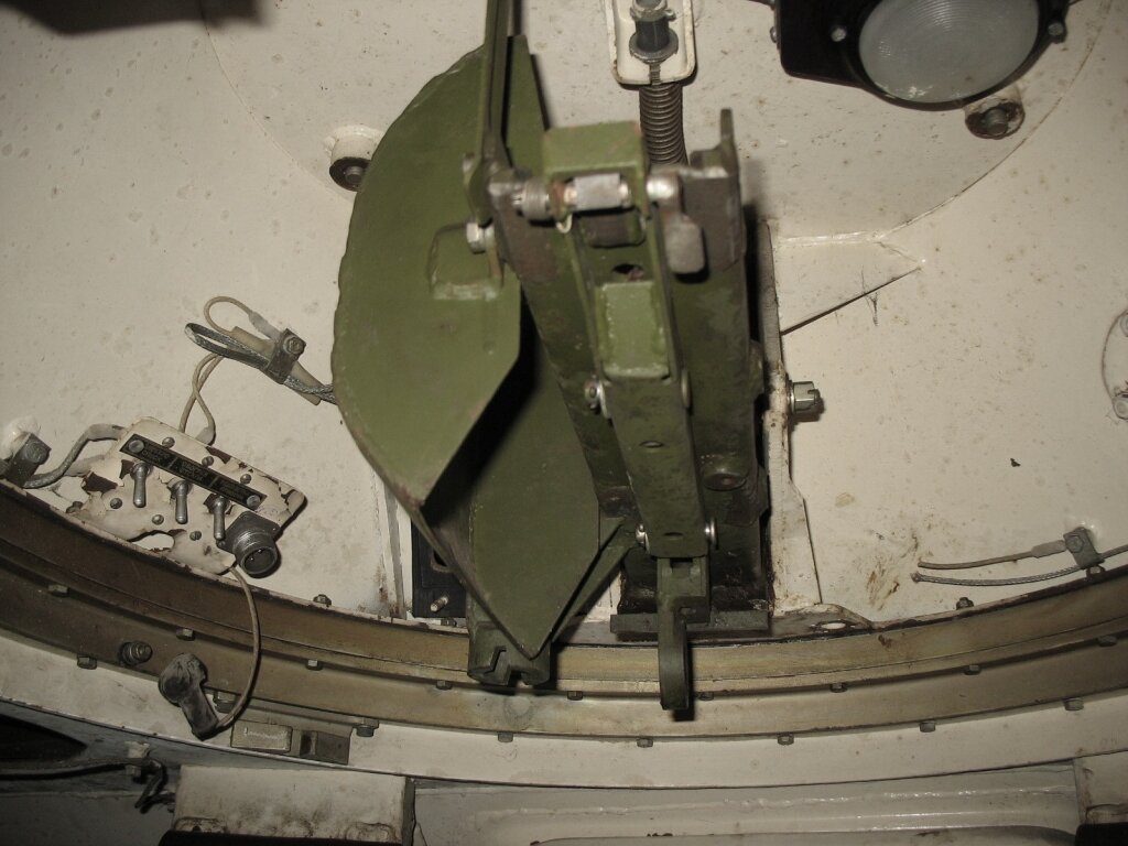
Both types of hatches are simple hinged hatches with no spring assist, likely because they are light enough to not warrant it. The hatch design was standard for virtually all postwar Soviet light vehicles, with an upturned lip on the perimeter of the hatch opening and a downturned lip on the perimeter of the hatch to form a physical barrier against bullet splash and leaks, particularly heavy water splashing when crossing water obstacles. Both hatches have a lock to keep them upright when opened, consisting of spring-loaded pawl which rests against the lip of the hatch openin under spring tension when the hatch is closed. When the hatch is opened by 90 degrees, the pawl catches on the raised lip around the perimeter of the hatch opening as shown in the image below, blocking the hatch from hinging back. To release the hatch, the pawl is pulled away from the lip by a ring pull, freeing the hatch to be pulled back and closed. The hatch is prevented from hinging further forward (or backward, in the case of the early model) by a nub welded onto the hinge.

The lock was borrowed from the AT-P, shown in the image below taken from an AT-P manual.

Directly in front of the commander is the R-123 radio, the standard radio for all armoured vehicles of the time. It is fitted on a shelf beneath the windshield, placed at a convenient position. The MT-LB is fitted with the R-124 intercom system, allowing internal communication between the commander, driver and one passenger in the cargo compartment. The R-123 radio and its power supply unit can be seen in the image on the left below, from Reddit user "BT-42". The image on the right below showing the empty shelf for the radio and its power unit was taken from this video.


The front wall of his station underneath the radio is a removable partition between the crew compartment and the transmission compartment, where the commander's control panel is fitted. The control panel has three power switches for his front-facing headlight, the heating for his windshield, and turn on power to his turret. With such a sparse selection of controls, the commander has very little physical authority over the essential functions of the vehicle. Next to the control panel is the commander's A-1 communications switchbox.


The commander is provided with a total of five vision devices in the MT-LB(V) and MT-LBVM. When his hatch is closed, his primary means of observing his surroundings is by the windshield to his direct front, two 54-36-5SB.BM periscopes in the 11 o'clock and 1 o'clock positions, and a B-2 vision block aimed to the right (shown below). The B-2 vision block is fitted with a large thickness of ballistic glass, but even so, it may not provide the same level of protection as the steel armour of the hull. The upside to its large size, however, is that it provides a large field of view. In the combat modifications of the MT-LB proposed by Muromteplovoz, the slits for the vision blocks were patched over and the vision blocks were replaced with periscopes, presumably improving protection in these zones. Bafflingly, in the MT-LBVMK, which is a minor modification of the MT-LBVM with the replacement of the NSVT with the Kord (using an adaptor pin), only the B-2 vision block in the cargo compartment was patched over and replaced with a periscope.


When seated at his station, the commander has good forward visibility as there is a windshield directly in front of him, supplemented by two periscopes, and the B-2 vision block in the side of the hull grants a view to the right. For all-round vision, the commander can use the PP-61B sight installed in his machine gun turret. The sight has a large field of view and permits easy scanning in azimuth using the rotation of the turret, although it does not have a high magnification. In the case of the MT-LBVM, the commander would use his PZU-5 anti-aircraft sight instead.


The two 54-36-5SB.BM periscopes use the same periscope unit as the 54-36-317-R periscopes in the driver's station of a T-54, T-55 and T-62, even featuring the same fixed handle, but they differ in the mounting system and do not provide the possibility of quickly cleaning the windows by quick-releasing the periscope and rubbing it up and down against a cleaning pad inside the housing. Nevertheless, the handles for doing so are still present on the 54-36-5SB.BM periscope. When riding around on rough terrain, the handle on each periscope allows the commander to steady himself with both hands.
The windshield is not armoured, and does not protect from firearms or artillery fragments other than small fragments and debris. When opened, the windshield cover functions as a visor, keeping rain and direct sunlight off the windshield. The windshields are each fitted with an SL-231B wiper to deal with any rain and snow blown onto the windshield, albeit only on a small swept arc. The windshield is a laminated glass assembly with built-in heating.
The commander's seat is mounted to the torsion bar cover of the first roadwheel pair. The seat is rather unusual in that it is a double swivel seat, in addition to standard features like backrest angle adjustment and seat height adjustment. Not only is the seat itself rotatable on its swivel, but the base of the seat itself has a swivel, allowing the seat to be positioned with an offset like in the photo on the left below. The reason for allowing the base to swivel is unclear, but it may have been to allow the seat to be pushed out of the way when moving in and out of the engine compartment corridor. It is very likely that the seat swivel feature was implemented to allow the commander to comfortably operate the machine gun turret, particularly when he must traverse it more than 90 degrees in either direction. The seat cannot be adjusteed in height, but the angle of the backrest can be adjusted in either direction, with the option of folding the backrest forward and flat onto the seat cushion.


With the installation of the TKB turret on the MT-LBVM, the seat was slightly modified by the addition of a cushion on the rear of the backrest. According to the manual, the commander is expected to fold the backrest flat against the seat and sit on the backrest to reach the optical sight in the turret, which is due to the increased height of the sight eyepiece in the new turret. Aside from this change, the seat remained the same.
The metal base of the seat is 280mm from the floor at the highest point, and the seat cushion is 330mm from the floor. When seated normally (and not using the turret for combat in the case of the MT-LBVM), the free space above the commander effectively gives him more headroom than the passengers in the cargo compartment despite his slightly taller seat, to approximately the same extent as the driver, who has a raised cupola, or more.


The metal base of the jockey seat in the middle is 550mm from the floor, and its cushion is only 20mm thick. The driveshaft cover is only around 260mm wide, and the jockey seat atop it is around the same width. Seated here, a commander of average height should expose only his head above the rim of the hatch, which gives him a free view towards the front and sides if the hatch is of the early type that hinges opens to the rear. If the hatch is of the later type that hinges open to the front, the commander has a much more restricted forward view in the tall gap between the hatch and the rim of the hatch opening. With a forward-opening hatch, the best position for the commander would be to sit on the hull roof, resting his feet on the jockey seat, or standing on the driveshaft cover.


It is important to note that, unlike purpose-built combat vehicles with a dedicated gunner, the commander was not furnished with a fire correction optic, which would have been a TKN-3B for the MT-LB. The commander's vision in combat is mainly limited by the fact that he is not provided with such a device, like his counterparts in combat vehicles such as BTRs, BMPs and tanks, where such a periscope was necessary for fire correction purposes. Moreover, not only did the commander lack the surveillance capability offered by the 5x magnification of such a device, he also lacked night vision.
Nevertheless, the all-round vision of the commander can be considered good relative to the commanders of older Soviet combat vehicles like the BTR-60PA and the BTR-50P. Like on an MT-LB, the commander of a BTR-60PA had a windshield in front of him, but it was only supplemented by a single vision slit in the hull side plate and a single rotatable TPKU-2 binocular periscope, while the commander of a BTR-50P had just three fixed generla vision periscopes arrayed in a 120-degree forward arc, and the squad commander was provided with an MK-4 rotating periscope with the option of installing a TKN-1 night vision periscope. Even when compared to contemporary vehicles such as the BTR-60PB, which had been upgraded with a more comprehensive set of vision devices, the MT-LB is quite good. If the three vehicle families are judged according to the quantity of vision devices and the breadth of view offered, the MT-LB compares favourably, especially considering that he has a swivel seat which allows him to comfortably achieve all-round vision using his machine gun sight, whereas these vehicles had fixed forward-facing seats.
However, compared to foreign armoured personnel carriers, the MT-LB was unremarkable or deficient in this regard. For example, the M24A2 cupola of the M113 had five periscopes covering a 180-degree forward arc, and the cupola could rotate so it was very easy for the commander to obtain an all-round view of his surroundings. The cupola of the French AMX-VCI was very similar as it was also rotatable and had five periscopes covering a 180-degree forward arc.
ARMAMENT
MT-LB, MT-LBV
The MT-LB was armed with a single 7.62mm machine gun in a turret for self defence purposes. If it were an armoured personnel carrier expected to take part in battle against enemy troops, a single 7.62mm machine gun would be wholly inadequate. Indeed, although the early BTR-60 models (BTR-60P, BTR-60PA) had just a single forward-facing pintle-mounted SGMB machine gun, there was the option of replacing it with a DShKM and even the possibility of mounting two additional SGMB machine guns on the sides. This was followed by an upgrade to a turreted KPVT and PKT pairing, making it possible to fight lightly armoured vehicles on favourable terms. However, the MT-LB was not built to be an armoured personnel carrier, as that role was already filled by the BTR-50P and BTR-60P. For the needs of towed gun crews, who were armed only with AKM assault rifles, a single 7.62mm machine gun provided a reasonable self-defence capability.
For the MT-LB and MT-LBV, an ammunition load of 1,000 rounds was specified until at least 1976. However, manuals from the 1980's list an increased ammunition load of 1,500 rounds, possibly a revision made as a result of experiences in Afghanistan.
TKB-01-1 TURRET

The MT-LB has a PKT machine gun installed in a small turret operated by the vehicle commander for self-defence purposes. Its main function is to serve as the base of fire for an artillery gun crew if they come under infantry attack, whereby each gun crew member becomes a rifleman while defending the gun emplacement or retreating from it. It also grants the possibility of the MT-LB serving as an overwatch weapon against an enemy infantry screening force moving ahead of their tanks, preventing the infantry from closing in and overruning the gun emplacement. With the exception of the RPG (the anti-tank weapon in this case would be the artillery piece) and the RPD or RPK organic to a Soviet motorized infantry squad, this transforms an artillery gun crew into the equivalent of a BTR-40 or BTR-152 squad in terms of firepower.

Housing the machine gun inside a small turret was the optimal design solution given the constraints of the MT-LB hull design. The machine gun turret fulfilled the same function as the bow machine gun of the AT-P prime mover, but the TKB-01-1 was capable of greater firepower as it could conduct all-round fire and provided the operator with better visibility, more ergonomic controls and a magnified optic. The TKB-01-1 was also directly analogous to a bow machine gun in that the operator controls the machine gun by hand rather than a geared mechanism, which allows the operator to manually stabilize his view and quickly lay the machine gun on a target. This was made easy due to the light weight, and thus low moment of inertia of a 7.62mm machine gun, enhanced by the long control handles, acting as a lever, although this is likely much less intuitive to control than a machine gun on a ball or pintle mount. A turreted system, particularly a non-intrusive type like the TKB-01-1, also increases the internal space available to the operator compared to a bow machine gun, where a rather large swept volume must be allocated inside the vehicle to accommodate the traversing arc of the weapon.
The turret is capable of 360-degree traverse, and the machine gun can be depressed by -5 degrees or elevated by +35 degrees, with the possibility of locking the machine gun at any elevation angle within this range. This is sufficient for engaging virtually all relevant ground targets, including infantry in high elevation positions at close ranges, but it is not suitable for air targets except low flying helicopters. That said, the basic premise of using a 7.62mm machine gun against air targets is somewhat suspect, so it is perhaps fair to say that an elevation limit of +35 degrees is sufficient for dealing with virtually all relevant threats. It is worth noting that the range of elevation is not drastically more than a traditional bow machine gun, but even so, the TKB-01-1 has an advantage in that the sight is fixed, and only the periscopic head elevates. Thanks to this, the operator can maintain a fixed, comfortable position on the eyepiece regardless of the elevation angle of the machine gun, unlike a sighted bow machine gun where the operator would have to contort in awkward ways to aim at the elevation extremes.
The commander elevates the machine gun using a set of two large control handles affixed to the machine gun cradle by a shared stem, and fires it using a thumb trigger button. On the left of the control handle stem is a gun elevation lock handle, marked (21) in the drawing below, also fitted to the cradle on the same crosspin, and loosely resting a clamp against a track fixed to the turret, marked (4) in the drawing on the left below. On the right of the control handle stem is symmetrically mirrored elevation lock handle. When the machine gun is free to elevate, the elevation lock handle will be at the same angle as the stem of the control handles, but when pulled back, the clamp is tightened against the track to lock the machine gun in elevation. The drawing below does not accurately portray how far the elevation lock handles must be pulled to clamp the machine gun firmly in place. The image on the right below, taken from a military film shared by the VHU YouTube channel, shows the control handles.


The image on the right below, from Reddit user "BT-42", shows the two elevation lock handles (behind and above the eyepiece of the sight) pulled sharply back relative to the control handles to keep the machine gun locked in place.


The set of controls described was the type used in the majority of MT-LBs. There was a design preceding this type, where the elevation lock handles were much longer, and there was only a single large control handle for the commander to elevate the machine gun. This early type is shown in the photo on the left below. The later type is shown in contrast on the right below. It is not known when the switch to the more common two-handle type was made.

The turret is very small, having a height of just 264.5mm and a maximum external diameter of 798mm. This was made practical by the small dimensions of the PKT, being a 7.62mm machine gun. The armour protection offered by the turret matches the protection level of the MT-LB itself, but due to its small size, the turret weighs just 109 kg with all internal equipment installed, though not including ammunition. The wall of the turret is a single 14mm plate bent into the shape of a truncated cone.
The main advantage of having a small turret rather than an external remotely controlled machine gun is that it enabled the commander to operate and access the machine gun without leaving the vehicle. This made it possible to clear stoppages and reload it from under armour. A secondary benefit is that the machine gun itself was better protected from damage, particularly from shell or mortar bomb splinters. At the same time, by having a turret built solely to house the machine gun, the weight and silhoutte of the turret was drastically smaller than a traditional turret, which makes it much easier to control manually and it improves the concealability of the vehicle.
In practice, the use of a turret rather than a simple pintle mount for the machine gun such as on early BTR-60 models effectively increased the firepower provided by the same weapon, because it served to isolate the operator from the outside environment, thus rendering enemy suppressive fire ineffective or less effective at the very least, while nullifying the issue of operators being unwilling to expose themselves to sniper fire - an issue which manifested when M113 armoured personnel carriers saw action in Vietnam and was only partly ameliorated by the addition of a gun shield. The same issue led to vehicles such as the Ferret scout car receiving a fully enclosed machine gun turret to replace its pintle-mounted machine gun.
The disadvantage of this method of laying the machine gun is that the shot dispersion obtained from it will be much greater than when it is fitted onto a fixed mount as a tank coaxial machine gun. According to the manual, the dispersion of a PKT or PKTM fired from the TKB-01-1 turret is considered normal if the radius of 80% of the impacts (R80) from a 10-round burst at 100 meters does not exceed 15 cm, equating to an angular dispersion of 1.5 mils. For comparison, the norm for a PKT or PKTM on a fixed mount is for 80% of a 10-round burst to fit within a 14 x 16 cm rectangle at 100 meters. Relatively speaking, the difference in the size of the dispersion area is enormous - fired from the TKB-01-1 turret, the 80% dispersion area is 707 sq.cm, whereas a PKT(M) fired from a fixed mount has an 80% dispersion area of just 224 sq.cm; over three times smaller. The precision of fire from the TKB-01-1 is somewhere between a PK fired from its bipod (R50 of 15.5cm, R100 of 35.5cm) and a PKS, which is a PK fired from a tripod (R50 of 7.3cm, R100 of 16cm). In terms of precision, it could be considered roughly equivalent to a free pintle mount. However, it is likely that when the elevation lock is used, the dispersion can be improved.
In practice, the possible ramifications are that the amount of ammunition needed to destroy point targets may be increased, and the effective beaten zone produced by the PKT(M) in the TKB-01-1 may be more constrained with regard to target area and range; while a tank coaxial PKT(M) may be capable of providing a high fire density on a small infantry unit concentrated on a narrow frontage at long range, the larger beaten zone from the PKT(M) in the TKB-01-1 may result in an insufficient fire density to effectively deal with the same target under the same conditions.
There is a dome light on the turret ceiling, located directly above the ammunition box, allowing the commander to conveniently handle the reloading and operation of the machine gun. Power to the turret is transmitted via a brush and a contact ring integrated into the turret ring. Power must be turned on for the commander to turn on the dome light, use the electric solenoid trigger on his machine gun control handles, and to use the sight window heater in cold weather.
The machine gun and the turret controls can be swung up to the maximum elevation angle of +35 degrees and locked using a travel lock on the turret roof in non-combat conditions to free up space in front of the commander.
The machine gun is sighted using the PP-61B periscopic sight, which is essentially identical to the more ubiquitous PP-61AM used on the BTR-60PB, differing only in that the PP-61B has a different glass insert with a range scale marked for the PKT alone instead of a KPVT and a PKT combination. The sight has a fixed 2.6x magnification and a large field of view of 23 degrees, and is well suited for low light conditions with an exit pupil diameter of 6mm. The aperture window on the turret is electrically heated to prevent fogging. The aperture window is the only protection provided for the sight embrasure in the turret; there is no shield to prevent fragments or a bullet from passing through the embrasure.


Having a magnified optic for the machine gun effectively increases its firepower as it extends the effective range of fire by aiding in the observation of enemy forces, the sensing of shots fired downrange, and by making it easier to adjust fire thanks to the range scales marked in the viewfinder.
Normally, the most significant downside of a fully enclosed turret is the reduction in the occupant's visibility, especially if the turret is not large enough to provide the occupant with multiple vision devices for an all-round view. This is the case in the much larger turret of the Ferret Mk. 2 scout car, which accommodates the upper torso of the commander, but has only a single forward-facing periscope that serves as the machine gun sight (via an unmagnified collimator). The TKB-01-1 avoids this issue by being particularly short so that when operating the machine gun, the commander's head does not intrude into the turret. The PP-61B sight has a periscopicity of 285mm, and as the viewing window is installed halfway up the height of the turret, this means that the commander's eye level is 153mm below the turret ring, or around half a foot.

The same design solution of having an uninhabited turret was used for the machine gun turret developed for the BTR-60PB, later shared with the BRDM-2, but differing in the scale due to the much larger bulk of the 14.5mm KPVT.

Because the commander's eye level is well below the level of the hull ceiling, he can freely use the vision devices embedded in the MT-LB hull when operating the machine gun turret without needing to adjust the height of his seat. To achieve a more complete all-round view, he must rely on the machine gun sight and rotate the turret. With a field of view of 23 degrees, it would serve quite adequately as a general observation device.
Due to the large weight of the 250-round ammunition box, the mounting cradle, the machine gun itself, and the additional weight of any collected spent casings, the weapon system is rather rear-heavy. To properly balance the entire setup, there is a coil spring equilibrator on the turret ceiling, which is hooked onto the gun mask. The machine gun recoils a short distance against a buffer spring on its mount, providing some recoil absorbtion and damping the firing vibration.
The machine gun is fed with 250-round boxes, a standard capacity for all armoured vehicles armed with PKT machine guns. The ammunition boxes are the same as those used in turreted BTRs, having a tall and narrow shape designed to fit more easily into narrow one-man turrets, as opposed to the square-shaped boxes used on pintle-mounted PKBs and tank coaxial PKTs. A total of four boxes are carried, one mounted next to the gun, and three more tucked in the front right corner of the commander's station. Spent cases and belt segments are ejected to the left, diverted by a deflector and collected in a fabric bag hanging beneath the machine gun. It is large enough to hold a thousand cases and their belt segments, which is the full combat load specified for the MT-LB, and it has a zipper along its bottom to empty out its contents. The photo below (courtesy of Viktor Viktor from Urban3r) shows the sheet steel hood affixed to the machine gun mount to serve as a case and belt deflector.
To reload the machine gun, it must be cranked to its maximum elevation angle as the low clearance afforded by the turret ceiling would otherwise prevent the top cover from being opened.
The drawing on the left below shows the box and the spring catch on its side for hooking onto a box holder to secure the box firmly in place, and the image shown on the right below (courtesy of user akstore), shows the carrying handle lifted.


The main drawback of the machine gun turret compared to a pintle mount is the inability to replace the barrel of the PKT without dismounting it beforehand. When the heat limit of the PKT barrel in continuous fire (500 rounds) is reached, the most practical option is to allow it to cool, rather than dismounting the machine gun to swap out the barrel.
The barrel shroud on the turret encloses the barrel up to the gas tube port. There are no issues with propellant gasses being vented into the shroud, because unlike the infantry guns, the PKT and PKTM were built with a proprietary, fully contained gas system, where the gas ported from the barrel is purged from the gas tube simply by returning up the port and back into the barrel when the pressure drops after the bullet has left the muzzle. Unfortunately, however, there is no fume extractor effect like in tank guns because the gas port is perpendicular to the bore axis, and so a substantial volume of fumes can enter the crew compartment via the receiver due to the open-bolt operating system of the machine gun.
The necessity of dealing with the issue of fume extraction was one of the ramifications of an enclosed turret such as the TKB-01-1, as by having this instead of an external mount, gunpowder fumes can accumulate rapidly during sustained fire, not just from the machine gun itself, but also emanating from the spent cartridge casings collected in the spent casing bag. The turret has no built-in ventilator to extract these fumes under normal combat conditions, relying instead on the high air flow rate developed by the supercharged ventilator when it is set to the overpressure mode. An air outlet built into the right rear quadrant of the turret wall (marked in the section A-A in the drawing below), fitted with a valve tuned specifically to open under the specified overpressure generated by the ventilator, ensures a controlled flow of air through the turret, around the machine gun, and through the outlet, thus extracting fumes. Given the close proximity between the turret and the ventilator, ventilation of the commander's station should be fairly strong while the machine gun is in use. Because the supercharger is in operation even in the basic ventilation mode of the ventilator, then as long as all hatches are closed, fume extraction is provided. The photo on the right below, taken from the Net Maquettes website, shows the bump on the right rear quadrant of the TKB-01-1 turret for the air outlet.


Firing the machine gun is done by pressing the thumb trigger button on the right handle. It is a solenoid switch which, when pressed, energizes the solenoid trigger mechanism on the PKT machine gun, causing it to fire.
The turret ring can be locked facing forward with a spring-loaded stopper for travel. To unlock the turret, the commander pulls out the stopper and locks it in the open position with by screwing in a nut. The race ring of the turret ring is mounted to a cast steel platform with bolts, and the armoured turret walls not only cover the turret ring itself but also overlap with the platform. The gap in the race ring is protected with fragment traps, to ensure that any bullet splash or other forms of fragmentation cannot jam the turret ring by traveling through the gap between the turret armour and the turret platform.


MT-LBVM

On the MT-LBVM, a new turret with an externally mounted NSVT machine gun was fitted, along with a complement of 1,050 rounds of ammunition in 7 proprietary 150-round boxes, with one carried on the gun mount and 6 rack spaces allocated in the center of the cargo compartment. By stowing ammunition this way, cargo space was restricted on the MT-LBVM, which made it impossible to tow an anti-tank gun or howitzer together with its ammunition and crew without stowing most of the ammunition externally, on the roof. The 150-round box is shown below.

Beginning from around the late 2000's, a new standard practice for MT-LBVMs and MT-LBVMKs was observed. Instead of the original proprietary 150-round box, they use a box adaptor enabling standard 50-round infantry ammunition boxes to be loaded onto the mount.


The photo below shows the ammunition racks occupied not by the specified 150-round boxes, but by pairs of standard 50-round boxes for the infantry DShK or NSV machine guns. When using these smaller boxes, there is a net loss of 300 rounds to the combat load.
There are ceiling brackets directly above the central ammunition racks for stowing the NSVT machine gun when it needs to be dismounted for extended periods, such as when transporting the MT-LBVM by rail.


TKB TURRET (NSVT)

The NSVT machine gun is a 12.7x108mm machine gun with a rate of fire of 700-800 rounds per minute, and a nominal effective slant range of 1,500 meters against low-flying air targets, and an effective range of 1,500-2,000 meters against ground targets. However, in practice, the effective range of the NSVT on the MT-LBVM will tend to be much shorter due to factors that will be detailed later.
On the TKB turret, the NSVT is fitted on a cantilever mount and controlled from within the turret using hand cranks. To facilitate the cantilever mount of the machine gun, there is a heavy equilibrator spring installed underneath and between the gun and the ammunition box, held inside a perforated frame. The mount permits a maximum elevation of 75 degrees and depression of -3 to -4 degrees.

On its cradle, the machine gun is mounted semi-rigidly, where its front mounting rails are not slotted into locks but simply ride in open-ended grooves, and the rear mounting eye is pinned to a shock absorber. Unlike most domestic 12.7mm machine gun mounts on armoured vehicles, there is no reciprocating recoil absorbing cradle, only the shock absorber, consisting of a stack of textolite buffer rings on a shank. The shock absorber is only mildly compressed during recoil, so there is very little displacement to dissipate recoil energy.

The machine gun is fed from the right, and the belt hanging between the ammunition box and the machine gun is protected from snagging on vegetation by a brush guard. The machine gun and its external fittings are not provided with any other form of protection, which is a relatively common shortcoming of externally mounted machine guns. Spent casings are ejected to the front and the spent belt exits from the left, where it is collected in a canvas bag for later reuse. When reloading, the commander elevates the machine gun to allow him to place a belt into the feed tray without getting out of the hatch and leaning over the top cover.
Aiming of the machine gun is done using the PZU-5 sight. It is a specialized anti-aircraft sight, with a 1x magnification and a very wide field of view of 50 degrees. It provides lead rings for aircraft traveling at up to 300 m/s, but no range scales or any markings appropriate for firing upon ground targets. The head of the sight is articulated by the gun mount with an external rod linkage. Together with its unmagnified view, the PZU-5 was an awkward choice for the MT-LBVM, especially in comparison to the NSV on the 6U6 universal infantry mount which was furnished with an 1OP81 sighting scope with a 3.5x magnification to engage ground targets in addition to the anti-aircraft reflector sight. Similarly, when used with the 6T7 infantry tripod mount, an NSV could be issued with an SPP optical sight with a variable magnification of 3-6x. Compared to these infantry mounts, the lack of a magnified sight in the TKB turret would have severely hamstrung the commander's ability to leverage the long range of 12.7mm rounds in combat conditions.

As the drawing above shows, the eyepiece of the PZU-5 sight is below the turret ring, but it hangs much higher than the PP-61B, such that the commander's head will be inside the turret when he is looking through the sight. This is due to the low periscopicity of the PZU-5, which was not an issue when it was originally used in a tank cupola, such as the remote weapon station cupola of the T-64B where the eyepiece will be at the same level as the periscopes and the eyepieces of the TKN-3.
Moreover, the horizontal positioning of the PZU-5 was also another bad compromise, and in more than one way. Firstly, there was a compromise between left and right eye dominant operators, as the sight is positioned so that the axis of the eyepiece coincides with the bore axis of the machine gun, which can be seen in the right image of the drawing above. It therefore does not favour one eye over another, but this also means that it is not particularly comfortable to use the sight with either eye, as the commander must twist his body to position his head properly regardless. Secondly, by increasing the penetration of the sight stem into the turret for the sake of positioning the eyepiece centrally, half of the turret volume became wasted space, as the sight stem physically prevents the front half of the turret from being used to accommodate the commander's head, or accommodate a larger hatch.

Besides using the PZU-5 sight, an alternate method of aiming the machine gun is to stand in the open hatch and use the iron sights while operating the controls in the turret. The controls are simple handwheels.
The traverse mechanism, shown below, possesses an intermediate degree of complexity, having a more refined design than the simplest hand cranks but lacking selectable gears for fine and coarse gun laying like the traverse mechanisms of larger, heavier turrets. Despite the light weight of the turret, a considerable gear reduction was needed in the traverse mechanism because the cantilever mount of its NSVT machine gun made the turret imbalanced and it introduced a large moment of inertia, particularly when a loaded ammunition box is present on the mount. This increased the effort needed to rotate the turret, particularly if the vehicle was on a slope.

The firing trigger is on the traverse handle. The top cover of the traverse flywheel is used to accommodate switches to control power to the trigger, PZU-5 sight heater, and its illumination. Between the cover and flywheel is a rotary firing circuit disconnect that prevents the machine gun from being fired when its barrel intersects with the radio antenna, and a warning lamp, marked (5) in the drawing below, lights up.

The elevation mechanism is a simple and direct worm gear drive. The elevation handle turns the worm gear, turning the geared head of the machine gun mount trunnion pin, thus raising or lowering the machine gun. Because a driven gear cannot rotate the worm gear, the elevation mechanism intrinsically fixes the gun in elevation unless the commander is controlling it. This provides a tighter elevation lock than the clamp-type braking mechanisms used on the anti-aircraft machine gun mounts on domestic tanks and in the elevation mechanisms of turreted BTR and BRDMs.


The armour consisted of welded 2P armour-grade high hardness steel plates set at various obliquities. The upper and lower glacis of the hull, together with the sloping "cheeks" connecting the upper glacis to the sponsons, all have a thickness of 14mm, while all other plates have a thickness of 7mm. This includes the sponson floor plates, the hull roof, and hull belly.


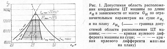


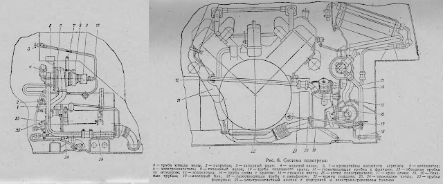

%20and%20238%20(2)%20power%20chart.png)
The YaMZ-238 develops a rather low specific power of 16.15 hp/l, which is to be expected due to its large displacement and low speed. When comparing it to the 6V53 of the M113A1 and M113A2, the rated power is only 13.2% higher, and the specific power is drastically inferior (16.15 hp/l to 40.61 hp/l). In general, for engines meant for lightly loaded vehicles, a high specific power is achieved by designing the engine for higher speeds, usually at the cost of low-end power.

Additionally, a notable advantage of the MT-LB drivetrain layout is that the front of the engine can be accessed quite easily by removing the rear engine compartment firewall. With the firewall removed, a mechanic is free to service or replace the belt drive mechanisms without needing to dismantle anything, unlike a typical car or truck where there tends to be very little free space in the engine bay for such tasks, which is also true for trucks equipped with the YaMZ-238, as the radial cooling fan is directly in front of the belt drives. The access available to the belt drives is shown in the photo below. The firewalls on the side and front of the engine compartment can also be removed to access a few other components. Only the left side of the engine compartment is largely inaccessible, requiring the engine to be removed.


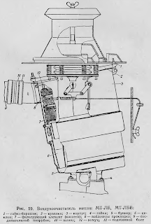


The turret can be locked facing forward with a stopper, functioning as the main travel lock. The gun elevation, being driven by a worm gear, does not require a travel lock. When marching over distances too short to justify stowing the machine gun away in the cargo compartment, the turret is locked and the machine gun is kept at a level elevation.
According to the manual, the dispersion of the NSVT when fired from the TKB turret is considered normal if the average radius of 80% of the impacts (R80) from three 10-round bursts at 100 meters does not exceed 60 cm, equating to an angular dispersion of 6 mils. For comparison, the dispersion from an NSV fired from the 6U6 universal mount (shown below), which also has a cantilever mount, is considered normal when the R80 dispersion of two 10-round bursts at 100 meters does not exceed 30 cm. With a doubling of the angular dispersion, the size of the dispersion area was quadrupled, which is even worse than the degradation of dispersion of the PKT in the TKB-01-1 turret relative to a fixed mount, despite the lack of geared gun laying mechanisms which are present on the TKB turret. It can be surmised that the recoil absorption of the gun cradle is ineffective, and the turret of the MT-LBVM is too light to adequately damp the recoil of the NSVT, leading to unstable recoil.

Its large dispersion, together with the lack of a magnified sight, made the NSVT of the MT-LBVM a highly unrefined weapon and a somewhat questionable upgrade over the preceding PKT. The need for the commander to exit his hatch to reload the machine gun is also a potential issue when fighting ground targets. Only when engaging air targets will the performance of the NSVT reach a modicum of acceptability, as the TKB turret could at least provide the utility of local air defence while under armour. Even so, due to the doubled dispersion relative to the infantry NSV on the 6U6 mount, it is unlikely that engaging aircraft at the rated 1,500-meter effective slant range is viable with the MT-LBVM. When engaging ground targets as fire support for an infantry unit, it may be best to have a mix of MT-LBV and MT-LBVM.
That said, when used at ranges where ammunition expenditure will not be extravagant, the destructive power of 12.7mm AP-I and API-T bullets enables an MT-LBVM to function as a credible fire support vehicle against lightly armoured vehicles and enemy forces in buildings or behind light cover. In the original context of its creation based on Soviet Army experience in Afghanistan, the poor shot dispersion and lack of magnification may not have been an issue when repelling ambushes, as the weapon system is still more than accurate enough to respond within and beyond the 300-meter effective range of RPGs and Kalashnikov rifles. Nevertheless, this is too niche of a justification, particularly in light of the design shortcomings of the turret.
PROTECTION
The MT-LB features a low level of protection, sufficient only for stopping 7.62mm ball rounds and light artillery fragments. Although a heavy truck would be more than capable of towing artillery pieces, a tracked prime mover with protection from bullets and shell splinters was needed to complement artillery pieces obligated to take part in direct fighting such as the 85mm D-48 anti-tank gun and 100mm BS-3 field gun. Being of a small size was also an important feature, as the prime mover of an anti-tank gun would often be concealed close to the gun emplacement in case it is needed for a quick escape.
The hull was constructed in such a way that all large sections were formed from smaller plates welded together. The lower sides and both halves of the sponsons are made from two plates, the roof is made from four plates, and the front of the hull itself has a complex shape. The hull belly consists of a five plates forming the flat belly and two pairs of smaller angled plates on the bow and aft sections welded together to join the floor to the front and rear of the hull. The use of thin and small plates generally tends to make it much easier to arrange production compared to large plates, but even so, the hull cannot be considered to have a cheap construction owing to the added labour costs of the extensive welding work.
The low height of the MT-LB was a fundamental component of its protection scheme, customary of all Soviet combat vehicles, and particularly so for an anti-tank gun prime mover. With a height of just 1,865mm to the turret roof (when loaded, with ground clearance of 400mm), and a hull height of just 1,600mm, the MT-LB is very low-slung and is easy to conceal. A low height reduced the probability of being hit, and more importantly, it also had a positive effect on the concealability of the vehicle. This was generally true for all vehicles that were expected to be targeted by direct fire weapons, even if they were not expected to take part in combat. As an artillery prime mover, the MT-LB had to be within close proximity to a concealed gun emplacement in case the crew must quickly relocate it, and for this purpose, the low silhouette of the MT-LB facilitated its concealment to help camouflage not only itself, but also the position of the anti-tank gun from enemy reconnaissance. When the gun or howitzer is deployed and in action, the MT-LB has to stay separated from the artillery piece at a distance of 100-150 meters, preferably concealed so as to not reveal the position of the gun battery.

The height reduction was achieved by rearranging the layout of components, without drastically changing any part of the drivetrain. The most major change was repositioning the crew so that, instead of sitting in a cabin directly over the gearbox, the seats were placed astride the prop shaft to the gearbox. The fuel system was also revised so that there were no longer fuel tanks under the floor panels of a cargo bed. Instead, it was distributed to the sponsons and to the two benches. The winch was removed, so that the space next to the engine compartment could be used to seat more passengers, who were previously seated in the crew cabin behind the driver and commander.

On the other hand, the MT-LBu, which was designed to be a universal tracked platform for rear echelon units, could afford to have a much taller superstructure with a greatly expanded interior volume, because rear echelon units were not expected to take direct part in fighting enemy forces, making the large silhouette of the MT-LBu largely irrelevant.
With a curb weight of just 9.7 tons, the MT-LB was 4.5 tons lighter than the BTR-50P, which had considerably thicker armour, but 1 ton heavier than than the BTR-60PA. Much of this difference is due to the large weight of a tracked suspension compared to a wheeled suspension, but it is also important to note that the MT-LB can be said to have slightly better front protection.
The armour consisted of welded 2P armour-grade high hardness steel plates set at various obliquities. The upper and lower glacis of the hull, together with the sloping "cheeks" connecting the upper glacis to the sponsons, all have a thickness of 14mm, while all other plates have a thickness of 7mm. This includes the sponson floor plates, the hull roof, and hull belly.
The upper plate, including the windshield covers, is sloped at 54 degrees. The transmission compartment roof and access panel are both 7mm thick, and sloped at 80 degrees. The lower glacis is sloped at 45 degrees, making it nominally weaker than the upper glacis, but it is supplemented by the trim vane. The trim vane is of an unknown material and thickness. The sides are flat on the lower half of the hull, but the sponsons are sloped at 23 degrees. The rear is slightly tilted by a few degrees, but is effectively flat.
Frontally, the armour is only immune to 7.62mm armour-piercing rounds (B-32 AP-I) at point blank range in a limited frontal arc of 90 degrees, which is largely due to the low thickness of the lower side armour. On the sides, protection from 7.62mm armour-piercing rounds is guaranteed only within an arc of 150 degrees and at a range of 250 meters. The sides and rear do not provide all-round protection from 7.62mm armour-piercing rounds, only ball ammunition. Protection from 12.7mm armour-piercing bullets is provided at point blank range but in a narrow arc of unknown size. Owing to the thin, flat lower sides, 12.7mm B-32 can pierce the armour from no less than 400 meters at an impact angle of 45 degrees, as the table below shows, with a probable limit of around 500 meters. With this in mind, the protected frontal arc from point blank range is likely to be no more than 60 degrees.
The table below from the 1992 paper "LAV Armor Plate Study" shows the ballistic limit of three thicknesses of MIL-DTL-46100 high hardness steel armour plates against 12.7mm B-32 armour-piercing bullets at an obliquity of 45 degrees. The third row lists an extra-hardened plate (XH) that does not represent the armour standard and it should be ignored. From the table, it can be seen that the velocity limit of 12.7mm B-32 on a 6.31mm plate at 45 degrees is 1,886 ft/s, corresponding to a range of 700 meters, and the velocity limit on a 7.31mm plate at 45 degrees is 2,176 ft/s, corresponding to a range of 400 meters.

Officially, the armour protects the vehicle from machine gun fire as well as from artillery shell splinters. The extent of its artillery protection will be limited to shells optimized for a high quantity of lighter fragments to improve soft target performance, or any shells with a naturally low number of heavy fragments. In general, this describes smaller caliber mortar bombs up to 120mm in caliber, 105mm to 122mm artillery shells and artillery rockets, but not 152mm or 155mm HE-Frag shells or HE-Frag rockets with heavy preformed fragments optimized to defeat light armour, such as the S-13OF aviation rocket. Ideally, for a prime mover of light artillery systems, the MT-LB would mainly be exposed only to weapons of a similar caliber and range when attacked with artillery fire, but in practice, with the U.S Army's move toward standardizing on the M109 155mm self-propelled howitzer, and the Bundeswehr and the British Army following suit by adopting the M109, 105mm howitzers stopped being the most numerous reference threat for the 1970's and the following decades.
The only notable factor in favour of the survivability of the MT-LB is that, when used as a prime mover for anti-tank guns, it primarily contends with the weapons available to the target (90mm, 105mm tank guns) to return fire and whatever light artillery is available for close support, with a reaction time quick enough to respond to a sudden call for fire. As a rule, this meant mortars up to 120mm in caliber, which was true even during WW2.
Overall, the protection profile was typical of the low end of Soviet lightly armoured vehicles of the period, corresponding closely if not directly to the BRDM-2. It was significantly inferior to most foreign armoured personnel carriers with light armour, most prominently the M113, which, on top of providing better bullet protection, also provided much better fragment protection owing to the favourable characteristics of aluminium armour. The MT-LB was also highly deficient in terms of mine protection, having no structural features adapted to resist mine blasts under the tracks. The conventional method of joining the belly plates to the side presents a weld seam close to the suspension, increasing the risk of rupture, and the use of high hardness steel to form the hull was also unfavourable in resisting blast damage. The best-protected aspect of the MT-LB is its front, where its ability to withstand .50 caliber machine gun fire is somewhat disproportionate to its all-round weakness.


Aside from the myriad of drainage points, there are two access panels in the belly, one large and one small. The small hatch is positioned underneath the power takeoff mechanism ahead of the clutch, and the large shaft is positioned underneath the engine. These access hatches may weaken the belly to mine blast to some extent, although there is hardly any mine protection at all to begin with.


To put out fires in the vehicle, there is a single OU-2 portable carbon dioxide fire extinguisher. No other form of fire protection is available.


The driver's station in the MT-LB is simple but spacious, although not as spacious as the commander's station. The driver has a conventional set of controls, with a pair of steering levers and three pedals. His station is also slightly unusual in that his hatch is mounted on a raised cupola. Unlike in many tanks, his instrument panel is placed directly in front of him, thanks to the free space afforded by the shelf underneath the windshield. At the driver's station, the available width between the driveshaft cover to the hull side wall is 780mm. From driveshaft cover to the sponson, there is an additional 380mm of width where the sponson is the widest, but only 150mm of additional width at the front where the drivers panel is located due to the inward slope.

The driver's seat is slightly adjustable in height, allowing a head-out driving position when raised to its highest setting for taller drivers. Setting the seat height is done by twisting an adjustment screw. The maximum range of motion is up to around 85mm, which can lead to issues for shorter drivers wanting to drive from an open hatch or taller drivers needing more headroom. Moreover, the adjustment mechanism does not allow quick changes in seat height, so it is not possible to rapidly transition from a head-out driving position to a closed-hatch combat driving position.


In the lowest seat position, the metal base of the seat is 270mm from the floor and the cusion is 340mm from the hull floor. Between the seat and the ceiling at lowest seat height setting, there is 857mm of space, but the driver's available headroom is actually larger due to a cupola, in addition to a slightly domed hatch. Relative to the ceiling, the raised cupola over the driver's hatch provides an additional 70-80mm of headroom, together with the domed hatch. Altogether, the actual available headroom is 930-950mm, taking into account the compression of the thick foam seat cushion.
Because the seat only raises straight up or down, it is evident that the clutch and brake pedals had to be positioned in such a way that the driver could reach them and fully depress them regardless of the seat position. This likely explains why these pedals were placed quite high off the floor, as illustrated in the images below. This may make it more tiring when braking when driving in a closed-hatch position.


The accelerator pedal is of the same design as found in the BTR-60 series, BRDM-2, and in domestic trucks, and is placed on the floor in the same way, which is another point of commonality that the MT-LB shared with domestic automobile design practice. The clutch and brake pedals are proprietary, however. The steering levers are situated between the driver's legs, like in an M113, but unlike in an M113, the handles of the levers are horizontal.

Interestingly enough, when the driver's position was moved during the rearrangement of the MT-L layout to form the MT-LB layout, the system of linkages for the gearbox gear shifting mechanism was completely unchanged. As such, the gear shift lever was now in a location that was too far for the driver to reach without leaning forward and to the right. The designers used the most rudimentary solution to this issue, which was to attach a lever extension.
The driver is provided with a personal fan for additional ventilation, which is a feature that is curiously absent for the commander's station. Unfortunately, unlike the majority of Soviet ground vehicles, it is not a DV-3 fan.
The driver's cupola is a protrusion on the roof where his hatch is installed, and the driver's three TNPO-170 periscopes are fitted on its front edge. The TNPO-170 periscope has a total range of vision of 94 degrees in the horizontal plane and 23 degrees in the vertical plane. Two versions of the driver's cupola exist. The early type, depicted in the drawing on the left below, was a single steel plate stamped into a smoothly sloping bulge like an overturned soup plate, and the hatch fitted atop it was smaller and more squarish in shape. The later type, shown on the right below, was a larger flat-sided structure constructed of smaller welded plates, accommodating a larger pill-shaped hatch. The switch to the flat-sided cupola occured at the same time that the commander's central hatch was switched to a forward-hinging type. The early cupola type can be seen in this photo.


With the change in the cupola design, the shape of the rear of the protective hoods for the three periscopes was modified accordingly. In both cases, the cupola provided additional headroom without any apparent physical need for it, as the TNPO-170 periscopes are tall enough that even the driver had the ceiling directly above him, he would be able to look through the viewing windows of the periscopes while wearing a helmet and holding his head upright. As such, it may be fair to say that the cupola is one of the few creature comforts included in the MT-LB solely for the sake of comfort alone.
The windshield is glass. The rim of the driver's windshield has an anti-splash rim, preventing bullet splash (fragments) from slipping through the edges of the windshield and its armoured cover. The windshield is very small compared to the windshields of most armoured vehicles that have one, including the likes of the BTR-60 series, but even so, it offers the driver a wide field of view compared to his front-facing TNPO-170 periscope and a great deal of convenience when driving in situations where it is either not desirable to drive from an open hatch or fully closed down. For instance, when entering a combat zone but not receiving fire, it is too dangerous to drive from an open hatch, but not dangerous enough to avoid using the windshield. It is also beneficial for non-combat driving in winter such as when using the MT-LB for administrative or logistical tasks, as the driver can stay in the warmth of the vehicle for the entire duration, rather than suffering from a frostbitten face and sapping the heat from the cabin if he were to drive from an open hatch.
The vision dead zone when looking through the windshield is not formally specified, but can be calculated to be around 4.5 meters from the top edge of the windshield to no more than 8 meters from the bottom edge, where the 80-degree slope of the transmission compartment roof dictates the dead zone. A windshield height of 1,400-1,600mm from ground level is used for this estimation. The photo on the right below shows the view from the driver's seat at eye level, showing that the angle of the transmission compartment roof was harmonized with the driver's head position so as to not obscure the driver's view.


Like in the commander's station, the driver also has a B-2 vision block on the side wall of his station to look out. The driver's B-2 vision block also provides him with a line of sight to the vehicle's only side mirror, allowing him a modicum of visibility when reversing. The side mirror frame is a very simple set of rods bolted together into a tripod. By unscrewing two of the bolts, the frame can be turned upside down, tucked behind the left headlight for rail transport. It may also be adjusted so that the side mirror is viewed from the driver's left TNPO-170 periscope instead of the B-2 vision block, as seen in this video clip.


In general, it can be said that the high mobility potential of the MT-LB is not constrained by driver visibility for the standards of the time. The inability to quickly switch from a head-out to a closed-hatch driving position is not ideal for combat situations, which is a recurring theme for the MT-LB. In most other situations, however, the additional visibility afforded to the driver by the windshield enabled him to get the most out of the vehicle while remaining almost fully under armour.
For general illumination, there are two FG-122N headlights on the corners of the hull. For additional illumination, there is a movable FG-16N headlight installed between the two windshields. It can be swivelled by either the driver or the commander, and it can be held at any position on its gimbal by a spring tension lock. It may be swivelled from side to side to illuminate objects that are not covered by the fixed headlights, or it may be aimed forwards to better illuminate the area ahead to extend the viewing range of the driver.
For nighttime driving, the driver is equipped with the TVN-2B binocular infrared night vision periscope. It has a fixed 1x magnification and a 30-degree field of view. To use the TVN-2B, the driver must first swap out the middle TNPO-170 periscope and then plug the power terminals of the TVN-2B into a socket, marked (2) in the drawing below, from the BT-6-26 power supply box, marked (6) in the drawing below.


When driving with the TVN-2B night vision periscope, an additional FG-200 IR headlight must be fitted on a post next to the left vision block, adjacent to the horn, as shown in the diagram on the left below. The photo on the right below (image from RecoMonkey, author unknown) shows an MT-LB with the IR headlight fitted. The range of vision is limited to 60 meters and only when the infrared headlight is on, as the periscope utilizes a single-stage gen 0 photocathode amplifier for each eye, so illumination is mandatory to form an adequate image. It is not possible to navigate at night using only the night vision periscope, as the driver will be unable to see the landscape and recognize landmarks.


CARGO
The cargo compartment is the primary space for stowing cargo. It provides a fully enclosed, protected volume, and when cargo is placed on the floor space, the center of gravity of the vehicle is raised minimally. As mentioned earlier in the Ergonomics section of this article, the nominal dimensions of the cargo compartment are 2,605 x 1,948 x 1,150 mm and the nominal cargo space is calculated to be 5.8 cubic meters. Modification 49, one of the simplified MT-LB models, had no passenger seating and no commander's station, and was lightened to 9.3 tons. The two fuel tank benches were removed to free up floor space and the same fuel capacity was maintained by enlarging the right sponson fuel tank.
The full displacement of the MT-LB is 14.6 cubic meters, inclusive of the transmission compartment and engine compartments. In contrast, the MT-LBu had a total useful volume of 13 cubic meters, enabling it to provide a passenger and cargo space almost as large as the entire internal volume of the MT-LB. This allowed free movement within the vehicle and the free installation of bulky equipment (as a rule, mechanical and with analogue electronics) used in command posts, mobile radar installations, and other special purpose vehicles.
To supplement this, the roof over the cargo compartment was designed to accommodate additional cargo. The perimeter of this cargo space has a number of racks with loopholes, used to secure crates with tie-downs. The roof space is narrower than the internal width of the cargo compartment, and is only a little over two thirds as long. The maximum weight of cargo that can be carried on the roof is not specified in any documentation, but it is known that a basic MT-LB can support a ZU-23-2 on its roof together with its two crewmen, which amounts to a load of over a ton.
One factor that intrinsically limits the size of the cargo that can be carried in the MT-LB is that its rear doors are limited in size, which consequently limits the size and nature of cargo that can be accommodated inside the cargo compartment compared to a ramp spanning the entire height and width of the compartment. With the backrests of the benches folded down, the rear doors essentially define the maximum dimensions of any container that can be passed into the cargo compartment and rested on the benches. Containers that span the full height of the cargo compartment from floor to ceiling could theoretically fit, but can't be brought into the compartment through the rear doors.
In actual use, the ramifications of the rear door size are more theoretical than practical. As a tactical tractor-transporter, the loading and unloading of cargo would invariably be done by hand due to the low-capacity of the vehicle. For individual ammunition crates containing two cartridges each, such as the crate shown below for 100mm HEAT rounds for the MT-12 anti-tank gun, this was practical.
The MT-LB is unsuitable for transporting large volumes of cargo internally. Its fully armoured hull was also a part of this limitation, as it effectively limits cargo access to the rear doors, making it infeasible to load up the cargo compartment with forklifts or cranes. This is in contrast to trucks, where forklifts can be used to load the entire length of the bed by folding down the side panels, or pallets can be lowered onto the bed from above. The volume of cargo that can be carried by trucks far exceeds the MT-LB, which makes the mechanization of loading and unloading cargo worthwhile. For its primary role as an artillery prime mover in particular, the unit of fire carried in and on the vehicle would all be in the form of individual crates containing two cartridges each, such as the crate shown below for 100mm HEAT rounds for the MT-12.

Funnily enough, despite the MT-LB being primarily a prime mover for T-12 and MT-12 guns, the cargo compartment does not readily accommodate 100x913mm cartridges. With a length of 2,605mm, the cargo compartment is not long enough for two crates of 100x913mm cartridges to be placed end-to-end. As such, more creative stacking layouts need to be devised to stow the specified unit of fire while also accommodating the full gun crew of 6 or 7 men (for the T-12 and MT-12 respectively). The possibility of stowing some of the ammunition on the hull roof is not excluded. On the roof, the width of the stowage area demarcated by the tie-down brackets is just wide enough for 100x913mm ammunition crates, as the photo below shows. Stowing external cargo in this way not only creates the risk of losing some of it to damage from enemy fire, but compared to the sponson spaces on the AT-P, it increases the influence of the external cargo on the center of gravity of the vehicle.
Due to the low thickness of the plates used to construct the monocoque steel hull of the MT-LB, the structure was extensively reinforced on most surfaces. The rigidity of the floor was augmented by U-beams. The longitudinal beams have no purpose other than structural reinforcement, but the transverse beams serve as covers for the torsion bars. Similarly, the thin roof - which was welded together from several plates - was reinforced with a cruciform frame and supported along the sponsons with struts to allow the MT-LB to haul heavy cargo on its roof. The shape of the hull at its cargo compartment contributed to this by having its sponsons shaped into a shallow arch. Additionally, it is possible to fit a load-bearing column under the center of the cruciform frame to bear the weight of heavy cargo carried on the roof.

When used as a prime mover, the MT-LB can tow a trailer or an artillery system weighing up to 6.5 tons while also carrying a nominal load of 2 tons of cargo internally or on the cargo deck. When driving without towing a load, the vehicle is rated to carry 2.5 tons of cargo, but it may only do so at the expense of its amphibious capability. If there is a need to preserve its ability to swim, a maximum of 2 tons may be carried. This is noted in the technical manual for the MT-LB, the military academy coursework of the Kazakh Al-Farabi National University, in the book "Советская бронетанковая техника 1945 - 1995", the article "МТ-ЛБ. Служба продолжается" by Sergey Suvorov in the May 2005 issue of the "Техника и вооружение" magazine, and a variety of other sources.
With its increased weight compared to the AT-P, the roles of the MT-LB could be expanded. At the same time, with a towing capacity of 6.5 tons and a nominal maximum cargo capacity of 2.5 tons, the MT-LB firmly remained within the light prime mover class. With its relatively large load-bearing capacity, the MT-LB was particularly suitable for hauling cargo across terrain impassable to trucks. If used as a personnel carrier, the large surplus loading capacity ensures that its offroading mobility remains high and the safety margin when swimming is improved by the increased reserve buoyancy.
Considering that the vehicle has a curb weight of just 9.7 tons (no crew, loaded with standard set of spare parts, accessories, coolant, oil, and fuel), this nominal cargo load amounted to 25.7% of the weight of the vehicle itself, which was not only superior to the 21.7% load capacity of the AT-P, but is also better than all foreign contemporaries. In real terms, this cargo capacity makes the MT-LB comparable to a lower-end 4x4 or 4x2 medium truck, but if rated according to payload efficiency, its performance is comparable to light trucks or pickup trucks rather than medium trucks. The heavier and more voluminous MT-LBu had a correspondingly larger cargo capacity of 4 tons, and given that its curb weight was 11.3 tons, the cargo rating amounted to an astonishing 35.4% of the vehicle's weight, which is excellent for a tracked vehicle.
The closest foreign counterpart to the MT-LB and MT-LBu in terms of cargo carrying capabilities was the M113, which is to be expected because its power-to-weight ratio was the closest to matching that of the MT-LB. The TACOM Standard Military Vehicle Characteristic Data Sheets from June 1962 state that the M113 has a cargo load of 3,860 lb (1.75 tons). Given that the basic M113 has a curb weight of 8.6 tons, this is 20% of the vehicle's weight. For comparison, the basic FV432 Mk. 1 has a laden weight (gross vehicle weight) of 14,770 kg and an unladen weight of 13,252 kg, giving it a cargo capacity of 1.5 tons, amounting to just 11% of the vehicle's weight. The FV432 Mk. 1 was followed closely by the Swedish Pbv 302, which was only specified to carry 1.2 tons, and with a curb weight of 11.1 tons, this meant that it could carry 10.8% of its own weight. All cargo loads or gross vehicle weighs were rated according to the limit for retaining amphibious capability.
All three foreign vehicles are distinguished from the MT-LB by the fact that they were personnel carriers, and as such, only had a cargo capacity sufficient for carrying a full crew and passenger load with their standard allotment of ammunition and personal equipment while retaining their mobility characteristics and remaining amphibious.
The maximum cargo capacity of the MT-LBV was reduced to just 1.5 tons and the maximum towed load was reduced only 4 tons, ostensibly in spite of the increase in traction that its wide tracks afforded. This is because the mobility characteristics of the MT-LBV were evaluated on more challenging terrain, including deep snow and swampy terrain, which placed harsher limits on how much it could haul. On the MT-LBVM, the cargo and towing capacity was technically unchanged, but officially, the tractor-transporter role was de-emphasized in favour of its new role as an armoured personnel carrier. Instead of a cargo load rating, the manual specifies its cargo load as a function of the passengers it can carry, specifying a load capacity of only 1,300 kg. Of that, the driver accounts for 100 kg, the ammunition accounts for 200 kg, and ten passengers accounts for 1,000 kg. Alternatively, a ton of cargo is carried. In both cases, the specified weights strangely omit the weight of the commander.
As a side note, the nominal rated cargo capacity of Modification 49 is 2.4 tons, and maximum rated capacity is 2.9 tons.
The loading limits according to the center of gravity of the vehicle based on the swimming safety threshold and limiting factors on land are given in the graph below, taken from the 1977 No. 2 issue of the "Вестник Бронетанковой Техники" journal, the article "Метод Анализа Компоновочных Схем И Параметров Вгм, Создаваемых На Базе Многоцелевого Гусеничного-Шасси". The swimming safety thresholds describe a basic level of maneuverability, buoyancy, stability afloat, operability of the main components while on water, and so on. The limiting factors on land are based on the maximum permissible load on any given roadwheel, the power to weight ratio, and so on.
The gross vehicle weight (GVW) limit is up to 13.2 tons if the center of gravity is within 2.55 to 2.6 meters behind the drive sprocket, which is a point just behind the engine. Realistically, however, this limit is inevitably exceeded when the full length of the cargo compartment is used to hold the load, which makes this impractical.

One of the limitations on the load-carrying capacity of the MT-LB is that each roadwheel has a maximum permissible load limit of just 1,100 kgf. As a matter of fact, the roadwheels simply do not have a structural load limit of 1,100 kgf; when driving at high speed on rough terrain, they most certainly experience much greater loads. This most likely refers to the maximum average load on a roadwheel, considering a distributed weight of 13.2 tons over twelve suspension units, taking into account that while the middle roadwheels bear the highest static loading, the front and rear roadwheels bear the strongest dynamic loads and are the most stressed overall.
It is, of course, completely possible to load more cargo than allowed according to the center of gravity, power-to-weight, and roadwheel loading limits, provided that mobility characteristics such as maneuverability, driving range and speed are sacrificed. While suspension loading is inevitably a factor, terrain plays a large part. In general, when driving on good quality dirt roads or on paved roads, the load limit can be relaxed without worsening the lifespan of the suspension. For instance, the ZIL-131 truck was rated to carry a load of 5 tons while towing a load of 4 tons when driving on paved roads, but when driving on dirt roads or off-roading, it can carry only 3.5 tons while towing 4 tons. Needless to say, due to the tracked suspension of the MT-LB, the expectations for its off-roading capability exceed the ZIL-131, which in turn places greater limits on its onboard cargo load.
Indeed, if mobility characteristics can be sacrificed, then the official rating given in the manual appears to be at least ultimately dependent on space rather than structural or suspension loading limits, as the TM-126, a demilitarized modification of the MT-LB used in the USSR, is specified to carry 4,000 kg of cargo in its expanded cargo compartment, which differed only in an increased height. Moreover, the MT-L was also specified to carry 4,250 kg of cargo, although this required the winch and some fittings in its cargo bed to be removed, lightening the vehicle but mostly freeing up the full bed for more space.
According to a technical manual for the MT-LB, the center of gravity of the vehicle is 2,267mm behind the axis of the drive sprocket when the vehicle is without cargo. With a driver and a cargo load of 2 tons, the center of gravity is shifted rearwards to 2,575mm from the axis of the drive sprocket. With the MT-LBV, the center of gravity of the vehicle is 2,296mm behind the axis of the drive sprocket when the vehicle is without cargo and 2,510mm with cargo. This is almost the exact midpoint of the distance between the axis of the drive sprocket and the idler wheel. When fully loaded, the height of the center of mass from ground level is 1.1 meters. When partially loaded for rail transport, the center of gravity of the MT-LB is 2,332mm behind the axis of the drive sprocket and 836mm above ground level. With the MT-LBV, the center of gravity of the vehicle is 2,296mm behind the axis of the drive sprocket when the vehicle is without cargo and 2,510mm with cargo, on account of its lighter rated cargo load.
With the MT-LBVM, the center of gravity of the vehicle is 2,293mm behind the axis of the drive sprocket when the vehicle is without cargo and 2,438mm with cargo.
During state testing, the average speed of the MT-LB a full cargo load and with a 6.5-ton trailer on dirt roads reached 26-32 km/h, which was almost one and a half times higher than the AT-L.
The main downside of the MT-LB in its primary role as a prime mover for anti-tank guns is that even with the ability to carry a cargo load of 2 tons while swimming, its amphibious capability does not include provisions for transporting a gun over water. Although it is more than capable of ferrying the gun crew and ammunition across water, the guns themselves must be left behind unless a bridge is available. As such, the amphibious capability was only meaningful for specialized combat modifications of the MT-LB designed to follow frontline units in maneuvers.
In terms of towing capacity, 6.5 tons was enough for the operational role of the MT-LB. In the Soviet Army, the MT-LB was most often used to tow lighter artillery pieces. The T-12 anti-tank gun, weighing only 2.75 tons, was manageable even for the AT-P. Heavier guns and howitzers like the MT-12 (3.1 tons), D-30 (3.2 tons) and BS-3 (3.65 tons) could still be towed by the MT-LB with ease. The D-20 howitzer, weighing 5.7 tons, was the heaviest artillery piece that could be supported by the MT-LB without a negative impact in its mobility specifications. For the MT-LBV, a towing limit of 4 tons still theoretically allows it to tow almost all of the aforementioned guns, excluding only the D-20.

The MT-LB featured a special shock-damping towing hitch to tow trailers and artillery pieces with less of an impact on ride quality. This type of towing hitch had been established as a basic feature for domestic prime movers for over a decade by the time the MT-LB entered service. The towing hitch is spring-loaded to damp longitudinal shocks when traveling over rough ground, particularly where it is possible for the wheels of the towed gun or trailer to be caught in a pothole. The hitch can be pushed forwards by 30mm or pulled backward by 55mm against a heavy coil spring, installed inside the reinforcing strut that runs across the hull. A shock absorber is present between the stem of the towing hitch and the spring, consisting of washers sandwiched by rubber buffer rings. The shock absorber begins to be compressed only after 25mm of travel by the towing hitch in either direction.
The shock damping provided by the towing hitch works both ways - it regulates the intensity of the load on the engine from the varying resistance of the towed item and the load on the brakes when stopping (for trailers or guns without brakes), and it helps to protect the chassis of the towed trailer.

Two traction force figures are available from MT-LB manuals. One manual states that the tractive force, with a coefficient of adhesion of 0.8, is 7,270 kgf without load and 8,790 kgf with a load.
Another manual states that the tractive force, with a coefficient of adhesion of 0.8 and a coefficient of resistance to movement of 0.04, is 7,448 kgf without a load and 8,968 kgf with a load.
MOBILITY
The mobility characteristics of the MT-LB were quite high for its time, in spite of the limitations of its suspension. The drivetrain layout consists of a longitudinally mounted engine with a transversely mounted gearbox. The engine - the heaviest component of the drivetrain - is mounted almost exactly on top of the longitudinal axis of the hull, with an offset to the left by 60mm. The auxiliary systems such as the cooling system and engine preheater are mounted to the left of the engine compartment. In total, the engine compartment was measured to take up 1.5 meters of width and 1.3 meters of length.
The installation of the powertrain was of the conventional type, where all major assemblies were individually mounted, aligned and then connected. Maintenance and minor repairs were done with the major components in-situ. Astonishingly enough, the AT-P had an integrated quick-replace powerpack where the engine, clutch, gearbox and steering unit were structurall combined into a single module. This feature, which was exceedingly rare in Soviet vehicle building practice, did not make it to the MT-LB, although understandably so due to its powertrain layout.
The maximum operating altitude is 2,000 meters above sea level, and the operating temperature range is -45°C to +45°C. An environmental humidity of 98% is permitted at a temperature of +15°C to +25°C. The vehicle can climb a 35-degree slope or a 25-degree side slope on dry soil, while carying the rated cargo load. It is rated to cross a 2.5-meter trench, and overcome a vertical obstacle with a height of 0.7 meters. This is despite the axis of the drive sprocket being only around 0.61 meters above ground level, implying that to climb such an obstacle, the MT-LB is driven into the obstacle to lift itself up on its sloping lower glacis, allowing the tracks to find purchase on the obstacle to climb over.
The ground clearance of the MT-LB is 425mm at its curb weight and 395mm when fully laden. The nominal ground clearance is usually expressed as 400mm. This ground clearance is unremarkable, and would have been even for a tank, which is contrary to expectations of the cross-country mobility of the MT-LB. In fact, with two large access hatches on the hull belly underneath the gearbox and the engine, at the front half of the hull, the driver must take particular care when driving over rough ground so as not to dent or rip the access hatches off on a stump, rocks, rubble, and so on.
According to the manual, the maximum speed of the MT-LB without a towed load but with an onboard load is 60 km/h, while the maximum speed when driving with a trailer is 45 km/h. With a trailer, the speed limit is highly dependent on what the trailer is, or indeed, what the towed artillery piece is. Note that, for postwar domestic guns like the D-44, D-48, T-12 and MT-12, the speed limit on a paved road is 60 km/h, as determined by the heat limit of the tyres. Finally, the average speed of movement on a dry dirt road of average quality with a load and with a trailer is 26-32 km/h. The average speed on snow and swampy or muddy terrain is not officially listed.
In the article "Универсальный Солдат Многоцелевой Транспортер-Тягач МТ-ЛБ", it is claimed that the average speed of the MT-LBV on deep snow and swampy terrain exceeded that of the MT-LB by 9-18 km/h. However, the manual states that 9-18 km/h is the average speed of the MT-LBV when loaded by 1,500 kg and when towing a trailer over deep snow or swampy terrain. It can only be assumed that an MT-LB under the same circumstances will either have a lower average speed, or it might only be able to bear a greatly lightened load, or it might bog down entirely.
As mentioned earlier, the layout of the MT-LB allowed the vehicle to be optimally balanced when performing its primary function as a prime mover, and its stability when driving off-road was additionally enhanced by its low height and long and wide track base. Having the center of gravity aligned so exactly with the center of the track base also increases the safety factor when making a turn at high speeds on terrain with a low coefficient of adhesion, as the intensity of skidding due to understeer or oversteer is minimized, if it occurs. Conversely, this also increases the steering resistance when making a turn, which is already high due to the large inertia resisting a turn at high speed, thereby increasing the load on the engine. However, as a rule in automotive design, the increased turning resistance cannot be considered a downside at all, as the safety factor provided by a driver having firm control over his vehicle is always the first priority.
The effect of having the center of gravity aligned with the midpoint of the track base is that it improves the steering dynamics of the vehicle, especially at high speeds and when moving on muddy or icy terrain. When afloat, the concentration of the drivetrain weight in the nose and middle of the vehicle was also beneficial as the rear half would have a surplus of buoyant force owing to the voluminous and empty cargo compartment. If it is afloat without a cargo load, the nose end of the vehicle is noticeably tipped down, but with cargo, the vehicle is level with the water's surface.
Additionally, the MT-LB can be transported by the An-12B. Owing to its modest weight, two can be carried in the cargo bay.
YaMZ-238V (M)

On the basis of the need to carry out long marches and sustained high traction to tow heavy loads, it was decided to use an automobile engine with a long service lifespan. This role was fulfilled by the YaMZ-238, which produced the necessary torque and had the durability to withstand high loading, but was deficient in many aspects of its performance partly as a consequence of acquiescing to these priorities. The YaMZ-238V is a specific variant of the YaMZ-238 made for the MT-LB, differing from the basic version by modifications in the air intake, the absence of a built-in radial cooling fan in the standard configuration for trucks with a conventionally placed front engine, and a different alternator. These modifications can be seen mainly on the front end of the engine, where the power takeoff gearbox and belt drives are situated.
The YaMZ-238V is a V-shaped 8-cylinder, water-cooled, four-stroke diesel engine with a rather large displacement of 14.86 liters and a rated power of 240 hp. It is naturally aspirated. The V-angle is 90 degrees, which is the ideal balance angle for a V8 engine. The two cylinder groups are symmetric, with 1,858 cc of displacement in each cylinder. Fuel is delivered by direct injection. The compression ratio is 16.5, which is quite typical for its class, with some examples such as the 6V-53 having a slightly higher compression ratio of 17. It is a pushrod engine with a gear-driven camshaft. There are two valves per cylinder. It has aluminium alloy pistons with a surface area of 132.7 sq.cm, and the crankshaft and connecting rods are made of machined steel. The YaMZ-238 is a slightly undersquare engine, with a cylinder bore diameter of 130mm and a piston stroke length of 140mm.
The YaMZ-238M is a multifuel variant of the YaMZ-238V with the ability to run on gasoline. Its characteristics are the same as the basic model when fueled with diesel, but if it is running on gasoline, both the power and torque characteristics degrade slightly, with the rated power diminishing to 220 hp.
The engine has a gray iron crankcase, giving it a much higher specific weight than high-performance engines with aluminium crankcases that are more commonplace among military combat vehicles. For tractors, a heavy engine contributes to the total load pressing down on the ground at the tracks or wheels, increasing the friction force, and thereby increasing the tractive force. This is the primary method of increasing drawbar pull. The close relationship between axle load and traction is one of the major reasons why the large weight of diesel engines relative to gasoline engines is not seen as a drawback, but rather, as a favourable trait for tractors, tractor-trailers and other prime movers. It is also partly for axle loading purposes that wheeled tractors have large, ballasted rear wheels.
According to the article "К вопросу выбора размерности для семейства перспективных танковых двигателей с высокой объемной мощностью при допустимой теплонапряженности" in the 1967 No. 5 issue of the "Вестник Бронетанковой Техники" journal, the mean piston speed of the YaMZ-238 is 9.8 m/s. Of particular note is the fact that the cylinders and pistons of the YaMZ-238 experience very low thermal stress owing to the low power to surface area ratio, which makes the engine less demanding in terms of cooling, facilitating longevity during marches with a towed load. On the other hand, this also meant that the MEP of the engine was low, only 7.6 bar.
The primary merit of the YaMZ-238 was its durability, as its weight came from its strongly reinforced construction, suitable for long-term work moving heavy loads. It also had relatively good fuel economy, which can be attributed to the low combustion chamber surface area relative to its displacement, on account of the large 1,858 cc displacement and the undersquare design of the engine.
However, although the weight of a strongly reinforced engine may be an acceptable compromise for civilian tractors, a heavy engine mostly presents downsides for a military tractor-transporter such as the MT-LB. Firstly, the large weight of the engine reduces the onboard cargo capacity; secondly, it reduces the permissible armour weight, which is important for a frontline combat vehicle; thirdly, it has a net negative effect on the high-speed off-roading capability of the vehicle. It could be argued that the increased traction available due to the weight of the engine is beneficial when towing a heavy gun or howitzer, and that the increased sprung mass of the vehicle improves ride smoothness, but in practice, the MT-LB also carries the gun crew and ammunition, and the increased weight of the engine simply means that less cargo can be carried. As such, from a weight standpoint, the YaMZ-238 engine was not the ideal choice for a tractor-transporter. The primary justifications for its use were its good torque and power output, and the availability of the engine.
At the midpoint of the development of the MT-LB, the YaMZ-238 had just recently entered mass production (June 1962). It was created alongside the YaMZ-236 as a family of universal workhorse diesel engines for civilian and military use, first seeing use in MAZ and KrAZ heavy trucks such as the MAZ-500 and KrAZ-255, and in the "Kirovets" tractor. During their shared development cycle, the YaMZ-238 lagged behind the YaMZ-236 by several months, although the projects were nominally progressing in parallel. In terms of design, however, the YaMZ-238 was evidently shown favour, as the 90-degree V-angle shared by both engines was ideal for the balance of V8 engines but not V6 engines, which require a 60-degree V-angle. While both engines became highly successful in their niches within the USSR, there was particularly high demand for the YaMZ-238 in heavy vehicles; as time went on, the number of military and civilian applications for the YaMZ-238 steadily expanded to include buses, combine harvesters, and off-road trucks, namely those made by the Ural automobile plant.
With this level of proliferation, the engine had become deeply embedded in the national economy, and the success of the engine also led to some older military prime movers being upgraded with the YaMZ-238, the main example being the GT-TB update of the GT-T prime mover. All of these peripheral developments made the MT-LB easier to maintain, as the status of the engine as an industrial standard meant that trained mechanics were easy to find throughout the USSR, and spares for both the YaMZ-236 and YaMZ-238 were plentiful.
The engine features a combination splash and forced lubrication system, with a wet sump. The main journals and connecting rod journals are lubricated under pressure, and splash lubrication is used for the cylinders. The use of a wet sump system contributed to the height of the engine, as the sump (oil pan) has to be rather large by its nature. In fact, the entire engine is tipped forward relative to the hull by 3.5 degrees on its mount to provide clearance for the sump, which has a characteristic hump shape to accommodate the oil filter intake. In turn, the gearbox is also tipped forward by 3.5 degrees.
An engine preheater is fitted for heating the engine crankcase via the coolant, as well as heating the engine and gearbox oil systems. It is the PZhD-44B or PZhD-44L diesel boiler with a heating capacity of 32,000 kcal/h. The PZhD-44B model consumes 6.6 kg (±0.5 kg) of fuel per hour, while the newer PZhD-44L model consumes 5-6 kg of fuel per hour, and the rated time needed to preheat the engine at an air temperature of 45°C to a starting temperature of 50-60°C is 30 minutes.

A number of accessories are directly mounted to the engine. There is an air cleaner on the crankcase at the rear of the engine, directly above the flywheel, and the alternator and the fuel supply group (a high pressure pump, a booster pump, a regulator and an automatic injection advance clutch) are placed in the valley between the cylinders. The starter is placed at the left of the flywheel. A fine fuel filter, and the coarse and fine oil filters are installed at the front of the engine together with the compressor and water pump. The clutch is firmly bolted to the engine as a single unit. The dry weight of the full engine unit, which is inclusive of all built-in accessories and the clutch, is 1,135 kg. The weight of the engine alone, without the clutch and accessories, is not known.
The size of the engine is unknown. According to the YaMZ website, the overall dimensions of the YaMZ-238VM are 1,225 x 1,005 x 1,035 mm (L x W x H). The length is inclusive of the clutch unit. For comparison, the dimensions of the 6V53 engine are 991 x 1,016 x 940 mm (L x W x H). It is worth noting that although the YaMZ-238V is longer - which is to be expected given that its length figure includes the clutch and that the YaMZ-238 is a V8 with a much larger cylinder bore (130mm vs 98mm), when the length is divided by the cylinder count, it actually turns out to be a proportionately shorter engine even before taking the bore size difference and the clutch into account. It is also worth noting that the right row of cylinders is displaced ahead of the left row by 35mm due to the conventional layout of the connecting rods in series on the crankshaft. This slightly increases the length of the engine, and introduces a small bending moment in the crankshaft. Aside from the length, the width of the engine is also well within reason.
Only the height of the engine could be seen as an issue for a compact engine compartment. The large height of the engine is particularly pronounced when it is installed inside the MT-LB owing to the limited height of its hull. Due to the accessories mounted on top of the engine, and the clearance needed below it, the engine takes up the entirety of the available vertical space in the engine compartment.
The YaMZ-238V has a four-point mounting system with shock absorbing, vibration damping mounts. There are two cross pins with rubber bushings held by horizontal clamp-type mounts at the rear of the engine (toward front of the vehicle), and at the front of the engine, there are two vertical shank bolt mounts with thick rubber cushions. The engine mounting frame is welded to the reinforcing U-beams along the floor of the hull, two of which are the covers of two torsion bar pairs. Owing to its well-damped mount and its perfect primary and secondary balance, the engine runs relatively smoothly and quietly in the MT-LB.

The engine has a rated power output of 240 hp at a speed of 2,100 RPM and a peak torque of 883 N.m at a speed of 1,500 RPM. The idling speed of the engine is 450-550 RPM, and the maximum governed speed is 2,225-2,275 RPM. Given that the vehicle has a curb weight of only 9.7 tons, the YaMZ-238 provided an excellent gross power-to-weight ratio of 24.74 hp/ton. With 2 tons of cargo and two crew members, represented as a nominal weight of 100 kg each, the gross power-to-weight ratio is 20.17 hp/ton, which is still good.
The specific fuel consumption is 175 g/hp.h, achieved at a speed of around 1,350 RPM. The nominal fuel consumption rate is 90-120 kg per 100 km or 43-44 kg per engine-hour, while the oil consumption is 2% of the fuel consumption. Converting from kilograms to liters, using the known density of the standard DL grade diesel fuel for summertime, the fuel consumption is 77-103 liters per 100 km, or 37.0-37.8 liters per engine-hour. This nominal rate was determined by a long-term military trial on a track consisting of a variety of terrain and road types.
%20and%20238%20(2)%20power%20chart.png)
For instance, it is written in the book "Opposed Piston Engines: Evolution, Use, and Future Applications" that, when running on diesel, the K60 generates a power output of 210 hp (157 kW) at a crankshaft speed of 2,380 RPM (final geared output speed of 3,750 RPM) and it only produces a maximum torque of 488 N.m. The large difference in torque is not only problematic in terms of net power at typical running speeds, but is also indicative of deficient load-bearing capability, especially in difficult terrain. The same was true for the Chrysler 75M gasoline engine used in the original M113, which put out 209 hp at 4,000 RPM but had a maximum torque of just 433 Nm. In contrast, the 6V53 diesel engine of the M113A1 and M113A2 generated 212 hp at 2,800 RPM and had a much more reasonable torque output of 607 N.m at 1,800 RPM.
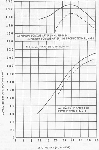
For engines intended for tractors, trucks and other heavily loaded vehicles, low-end torque is emphasized for the sake of more low-end power, because the task of hauling a load becomes uneconomical if a high-revving engine is used, as it would need to be driven at a high rotating speed to develop the power needed for the task. Diesel engines are favoured for these classes of vehicles mainly for this reason, and the YaMZ-238 was designed with this role in mind.
Moreover, when driving cross-country and when towing or transporting a load, the engine is rarely running at its peak power, and when accelerating, the transmission tends to be upshifted around the rated speed (either automatically or manually), so the engine is able to develop its rated power for only a fraction of the total driving time in each gear. Rather, because the engine accelerates together with the vehicle, it is important to look at the entire power curve leading up to the speed at which the rated power is developed. As the table below shows, the power curve of the slower-running YaMZ-238 is much more favourable for the purposes of a prime mover, cargo transporter or personnel carrier operating in bad terrain, and in virtually all circumstances, the average power delivered by the YaMZ-238 is much greater owing to the shape of its power curve.
| Engine speed (rpm) | 6V53 (hp) | YaMZ-238 (hp) | Power difference |
| 1,500 | 125 | 186 | 48.8% |
| 1,600 | 136 | 199 | 46.3% |
| 1,700 | 145 | 209 | 44.1% |
| 1,800 | 153 | 218 | 42.5% |
| 1,900 | 162 | 227 | 40.1% |
| 2,000 | 170 | 235 | 38.2% |
| 2,100 | 177 | 240 | 35.6% |
No data is available for the 6V53 below 1,500 RPM, but when the existing data is graphed using the best fitting curve (r^2 = 0.996), it can be extrapolated that the gap between the YaMZ-238 and 6V53 is widens at the same rate down to idling speed. In practice, the net power available at the gearbox can vary greatly, and the best case scenario for the 6V53 is when the vehicle is cruising or accelerating gently, where the transmission permits the torque converter lockup clutch to engage so that there is no power lost to the torque converter, thus improving fuel economy. Refer to this page on the TX-series transmissions on the M113 series for more details on how a torque converter affects the net power available at the gearbox, even with a gearbox that has a torque converter lockup in all gears.
On top of its favourable power curve, the YaMZ-238 has a notable advantage in fuel consumption, as the 6V53 has a specific fuel consumption of 188 g/hp.h compared to the 175 g/hp.h rate achieved by the YaMZ-238. Additionally, the fuel consumption rate will also tend to be much lower for an MT-LB in practice, as its good power curve allows it to drive at an efficient engine speed at higher gears even while towing a heavy load, whereas an M113 would tend to require the engine to be driven at high speeds with the gearbox in a low gear under the same circumstances.
However, in spite of its good power curve, the YaMZ-238 loses out in terms of engine dynamics. To quantify the qualities of the engine dynamics, two metrics are used - engine flexibility (adaptability) and engine elasticity. The engine flexibility (adaptability) coefficient is 1.086, obtained by finding the ratio of the peak torque to the torque developed at the rated power. This figure is also known as the torque backup, torque reserve or torque rise when expressed as a percentage. In this case it is 8.6%. High engine flexibility is important for negotiating terrain that imposes high fluctuating engine loads rather than constant loads, and is therefore responsible for providing a high cross-country speed.
Additionally, to quantify the characteristics of the power band, the engine elasticity coefficient is used. The wider the power band, the lower (better) the coefficient. For the YaMZ-238, the coefficient is 0.71, as determined by dividing the engine speed for peak torque by the engine speed for peak power. A wide power band contributes to the ease of driving the tank in various types of terrain, because it means that downshifting is often not necessary when the tank slows down as the engine produces a large amount of power at a wide range of speeds.
In both metrics of the performance of the engine's dynamics, the YaMZ-238 is poor. It is surpassed in both respects by a considerable margin by the 6V53, which had a flexibility coefficient of 1.126 and an elasticity coefficient of 0.64 (the same as all other 53-series engines). However, the turbocharged 6V53T, which provided more power and matched the YaMZ-238 in torque, had drastically worsened dynamics, with a flexibility coefficient of 1.093 and an elasticity coefficient of 0.786.
ENGINE ACCESSORIES
The engine accessories were installed in a layout similar to a truck engine. Unlike the engines used in domestic tanks and other military tracked combat vehicles, the starter and the alternator are separate devices on the YaMZ-238 series. The starter is placed under the left cylinder bank, and connects to the flywheel. The G290 alternator is mounted on top of the engine, and is driven by a belt from a power takeoff at the rear end of the engine crankshaft. The G290 is a three-phase synchronous AC alternator rectified to produce a DC output. It has a rated output of 3.75 kW.
There are four belted drive connections on the engine, two belts at the camshaft for the engine to drive the alternator and air compressor, and two belts for the engine to drive the cooling fan and coolant pump. Smooth wedge-type belts are used, with the transmittable force limit controlled by a spring-loaded tensioner. The same type of belts with the same width can be found in a number of Soviet trucks, and can be used in the MT-LB. Belts of a non-standard length can be used as long as tension is adjusted appropriately. Tensioner adjustment is depicted in the drawing below. An interesting feature of the drive belt system inherited from standard design practice in domestic trucks is that two separate drive belts are used for more heavily loaded units, which in this case were the alternator and cooling fan. This may have been a way of standardizing on a single belt size for all connections. It may also provide an additional element of redundancy to improve the reliability of the belt drive, on top of the natural tendency of such belts to slip rather than break when the loading force exceeds the maximum friction force.

The engine access panel is very large, and its opening follows the entire perimeter of the engine compartment (excluding the cooling system) without any overhang of the hull roof. In this way, it is very similar to the bonnet of a truck.

The power supply system operates at a nominal voltage of 24 V and a load current limit of 120 A. This likens it to a truck electrical system and distinguishes it from domestic tanks and other armoured fighting vehicles, with the exception of the BTR-60 and BTR-70 which also operate on 24 V, and like the MT-LB, use engines and engine accessories meant for trucks and specialized wheeled vehicles.
There are two 6ST-140 lead-acid batteries, connected in series. Each battery has a voltage of 12 V and a capacity of 140 Ah, thus providing an operating voltage of 24 V at a capacity of 140 Ah. The design of the 6ST-140 battery is rather interesting as it is actually a wooden box containing a battery bank, consisting of six smaller, individual self-contained batteries. The lid of the box contains built-in conductor plates to connect the batteries and the two terminals for wiring up the battery unit.
AIR INTAKE
The engine air supply system was conventional for Soviet military vehicles. It features a two-stage air cleaner with a multicyclone precleaner, and an oil mesh filter pack for fine particle separation. The inlet pipe to the air cleaner leads to the air intake on the engine access panel, so that air enters from above, passes into the cyclones, then travels upward into the oil mesh filters before exiting from the side. The air cleaner assembly is rather tall, and together with the alternator, it is partly responsible for the height at the engine compartment. It does, however, facilitate convenient access to the oil mesh filters for cleaning, and the same can be said for access to the alternator for servicing.

The air intake on the engine access panel consists of a protective cap on top of a hole, and more often than not, there is also an additional intake hood bolted onto the cap. The hood is a simple metal cover with a mushroom dome top, the underside of which is covered with a mesh. This hood is intended to reduce the dust ingested when driving in dusty environments, eliminate water ingestion when crossing water obstacles, and eliminate the ingestion of leaves and pine needles when traveling in forest environments. When not in use, the hood is kept in the transmission compartment, but in practice, it is almost always fitted since there is practically no reason to not use it.
Since the engine access panel is routinely opened for various reasons, a spring-loaded sealing mechanism was integrated to the inlet flange of the inlet pipe to connect the air cleaner to the air intake. When the access panel is closed, the seal is pressed tightly against the intake opening.


When it is desirable for the engine to induct heated air, such as during winter, a flap on the side of the air inlet pipe can be opened by pulling a handle on the engine compartment firewall behind the commander. Opening this flap allows the engine to draw air from both the atmosphere and the engine compartment, which is heated by the engine itself.
The disadvantage of the overall layout of the air intake system is that the inducted air has to make multiple sharp turns while travelling to the engine, which results in a higher intake air pressure.
The air filters and air purifier cyclones for the engine require cleaning after 25-30 engine-hours.
PNEUMATIC SYSTEM

It is a light duty compressor of a standard model, standardized between the a wide range of wheeled vehicles such as the BTR-60 series, BRDM-2, ZIL-131, Ural-375 and some tracked prime movers like the ATS-59. In the textbook "Основы Теории И Конструкции Танков, Боевых Машин Пехоты Бронетранспортеров И Армейских Автомобилей: Часть Вторая", it is referred to as the ZIL-131 compressor. The only difference in the compressors used in these vehicles is in how they are mounted and the diameter of the belt wheel to regulate the compressor crankshaft speed when used together with different engines. It is much different from the AK-150 series compressors used in domestic tanks, which generate an operating pressure of 150 kgf/sq.cm. The compressor generates and maintains a pressure of only 6-7.9 kgf/sq.cm (588-774 kPa) in the pneumatic system. A total of 43 liters is stored in two compressed air bottles, mounted in the transmission compartment.
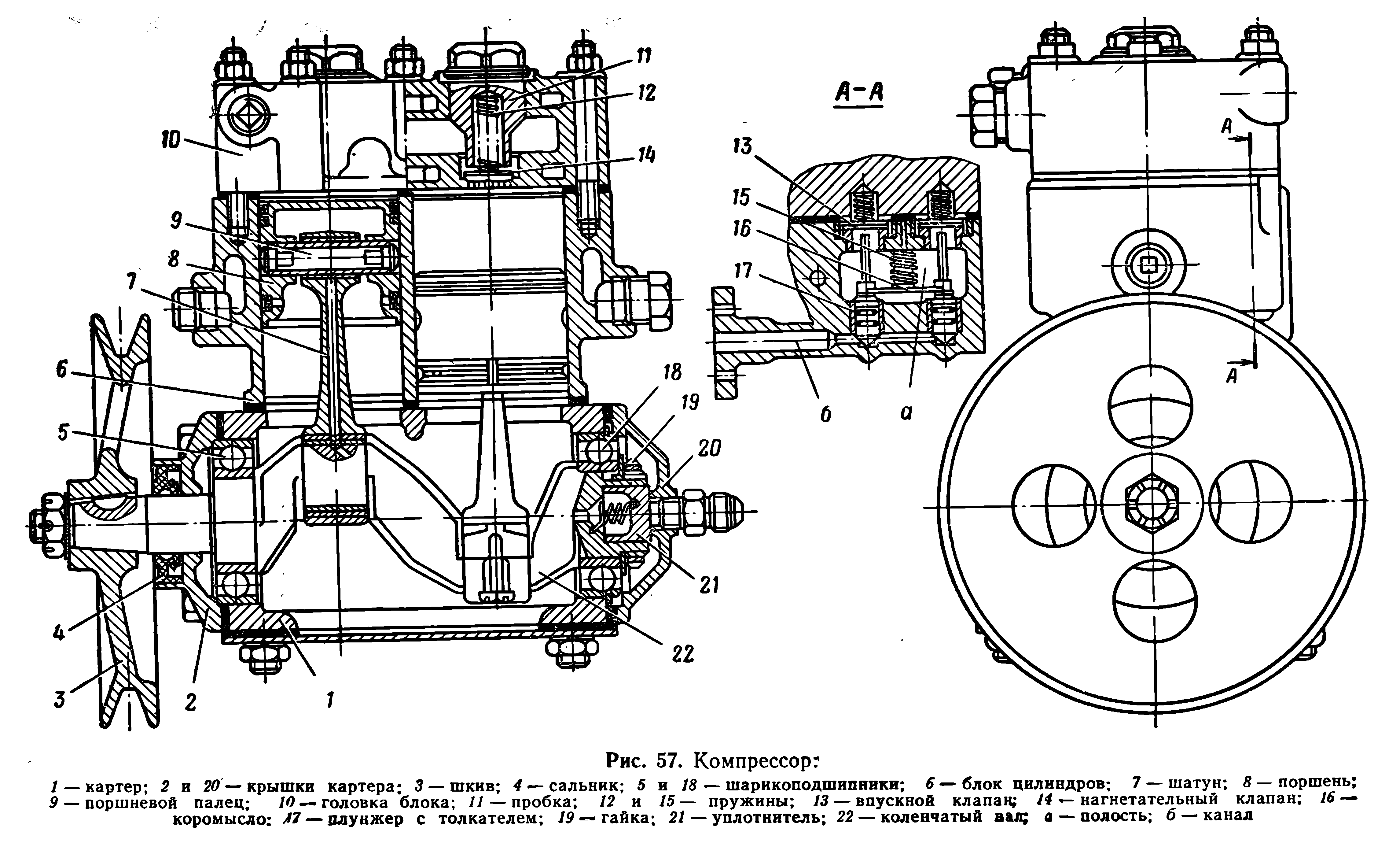
Unlike the pneumatic systems used in domestic tanks, the pneumatic system in the MT-LB is limited to auxiliary features within the vehicle itself. It serves to power the pneumatic brakes and to operate the windshield washers. There is no air start system for the engine. Like other prime movers, the pneumatic system in the MT-LB was mainly fitted to power the pneumatic brakes of a towed trailer, if such a system is present.
COOLING SYSTEM

The cooling system of the engine is of a conventional type, with aluminium radiators and a normal operating coolant temperature of 75-98°C, and the maximum temperature is 105°C. 55 liters of coolant is used in the system. The cooling system is interconnected with the preheater, as the coolant pipelines are shared. This also means that when preheating the engine, some heat will be lost to the environment through the radiators, thus increasing the preheating time. To mitigate this, a set of ballistic louvers over the radiators can be closed.

The ballistic louvers protecting the radiator intake are shown below. The radiator area is 1,202mm long and 415mm wide. Each individual louver is hinged and connected to a bar, and the intake can be shut by pushing forward a handle connected to this bar. The handle is behind the driver's left shoulder.

The oil radiators of the engine and the gearbox are stacked on top of the water radiator for the engine. Air is drawn through the radiators via the intake louvers, where it is ducted to the centrifugal cooling fan and is then expelled. It is worth noting that the cooling fan evacuates any water that enters the radiator duct from the radiator intake by its strong airflow, but when the engine is at rest and the fan is off, rain water can accumulate in the ductwork since it is directly underneath the radiators, and the intake is ducted to the fan. In the long term, this can result in premature corrosion, so a drainage port on the underside of the housing has to be opened when the MT-LB is parked for long periods. This is done with a pullstring mechanism in the driver's station. The image below, taken from a video, shows the intake duct to the cooling fan.

The cooling fan is powered by a belt drive from the engine via a reduction gearbox. The fan gearbox is mounted coaxially to the engine, so like the engine, it is also tipped forward by 3.5 degrees.

The cooling fan system was implemented in a fairly innovative way. Air flows in through the center and exits radially. To direct the outflow, the fan housing has a spiral shape and is ducted to the exhaust outlet, shared with the engine exhaust. Here, the relatively cool air from the radiator mixes with the engine exhaust, cooling it down before it is expelled. More importantly, due to the combination of the low density of the hot radiator exhaust air and its high velocity as it is blown past the engine exhaust port, a low pressure zone is created for the engine exhaust, leading to a significant reduction in exhaust backpressure. In doing so, the net engine power is increased.

However, aside from the advantages of the design, it is also important to note that with this implementation, the radiator and the exhaust are placed side-by-side, which is generally undesirable because it introduces the possibility of exhaust recirculation in the cooling system, where heated air from the exhaust re-enters the radiator under the strong draft created by the cooling fan due to its close proximity. This would normally have a negative impact on the cooling efficiency of the system, although it is mitigated when the vehicle is in forward motion by the incoming stream of air and the angle of the exhaust flaps, as shown in the image on the left below (courtesy of Lex Kitaev), or when it is moving forward with the engine at high speed, where the strong jet of exhaust blows clear of the hull. At low engine speeds and when idling, the air stream is too mild, but the weak exhaust is only able to open the flaps partly, and in this position, the flaps work to deflect the exhaust gasses rearward, as shown in the image on the right below. In this way, exhaust recirculation can be virtually eliminated in all circumstances except when the vehicle is moving in reverse. The primary issue with this solution is that the flaps will introduce some additional losses on their own by increasing the exhaust backpressure, varying with how widely they are opened.


The exhaust is mainly protected from bullets and fragments by a set of internal vanes angled to shield the exhaust port from ground level threats. The flaps do not provide any notable protection due to their low thickness. With the engine running, the flaps only serve to prevent the exhaust flow from blowing forward, but when turned off, the flaps fall to fully close over the exhaust port to prevent rain accumulation inside the exhaust ducts.
FUEL SYSTEM

A total of 520 liters of fuel is carried in an MT-LB, spread across four fuel tanks located in the cargo compartment. The fuel system is divided into two groups, left and right. There is a sponson fuel tank as well as a floor fuel tank on each side. Each side contains 260 liters of fuel. The sponson and floor tank in each group is interconnected, and both groups are connected to a single fuel pump.

The onboard fuel provided the MT-LB with a nominal driving range of 500 km on paved roads. If fitted with the YaMZ-238M engine, the driving range with gasoline is 350-380 km. The nominal fuel consumption rate while carrying out unspecified on-site "work" is 8 liters per hour, or 13.5 liters per hour when doing trenching work. The fuel consumption rate while towing a nominal load is 110 liters per 100 km, or 31.5 liters per engine-hour.
When driving with a full fuel load, both right and left fuel tank groups are drained simultaneously by an equal amount. The fuel outflow is from the floor tanks, so if the sponson tanks are filled, they function by replenishing the floor tanks. The effect is that the sponson tanks are emptied first, which can drastically reduce the vulnerability of the MT-LB to fuel fires if it is under enemy attack, as the sponson tanks would tend to be empty or near-empty while the floor tanks are very difficult to hit.
Different grades of diesel may be used depending on the weather conditions. In non-winter weather conditions where the ambient temperature is above 0°C, the DL grade "summer" diesel fuel is used. It has a density of 0.86 kg/liter at a nominal temperature of 20°C and has a flash point of 62°C. In winter conditions where the ambient temperature is -30°C and above, the DZ grade "winter" diesel fuel is used. It has a density of 0.84 kg/liter and has a flash point of 40°C. In arctic conditions where the ambient temperature is -50°C and above, the DA grade "arctic" diesel fuel is used. It has a density of 0.83 kg/liter and has a flash point of 35°C. The DA grade is essentially a slightly heavier form of kerosene. If the temperature drops below 0°C during the course of an operation and DZ grade fuel is not immediately available, it was possible to adapt DL grade fuel for winter use in field conditions by adding kerosene.
Because the floor fuel tanks had to support cargo, it is of a particularly robust design with thick inner partitions, such that despite having a much smaller capacity than the sponson tanks, the floor tanks weigh 28.5 kg each - more than double the sponson tanks (12.9 kg).
TRANSMISSION

The transmission of the MT-LB is housed entirely within the nose of the hull. The transmission is a fully mechanical, manual type, consisting of a synchromesh gearbox with an integral steering mechanism, two stopping brakes, and the final drives. Like the engine compartment, access to the transmission compartment and all the parts within is made easy by a large access panel. Additionally, removing the transmission compartment partition at the commander's station provides access to the rear of the gearbox, where some linkages are located.

For the purposes of a prime mover, the use of a manual transmission was not entirely ideal compared to a transmission with a torque converter in terms of ease of driving. With a torque converter, engine stalling becomes much more difficult, and very low speed driving becomes much more practical. For a prime mover, it may be necessary to drive at very low speeds when navigating a difficult path while carrying or towing a heavy load, so a great deal of torque is desirable for confident driving along with protection from stalling, which could be ensured by a torque converter. At the same time, from an economical point of view, the enormous losses in a torque converter at such low speeds makes it highly unattractive to have them in prime movers that are routinely driven this way. Moreover, it could be argued that the high gear reduction for low speed driving is adequately provided by the steering mechanism with the gearbox in 1st gear.
The clutch is installed onto the engine as a single unit, as shown in the image on the right below, and a cardan shaft connects the clutch output shaft to the gearbox, which then connects to the final drives. The clutch is a multidisc dry friction type with cermet friction pads, with a special friction disc hub designed to provide torsional damping, limiting the vibrations transmitted from the gearbox, prolonging the lifespan of the clutch itself along with the engine under conditions of heavy load. The general design of the clutch is very similar to Soviet truck clutches of the time, which is a trait that is shared with wheeled BTRs. While lighter trucks used a single-disc type, including the dual-engined BTR-60 and BTR-70 series (which had one clutch for each engine), two-disc clutches of this design were used on heavier trucks like the Ural 4320.


There is a bevel gear splined to the drive shaft on the clutch, which is part of a power takeoff mechanism integrated ahead of the clutch. The mechanism consists of a mating bevel gear which drives the bilge pump. The bilge pump is the protrusion beneath the clutch in the image on the right above. The blanked-off socket on the left of the clutch was formerly the power takeoff for the winch in the MT-L.
The gearbox is a two-shaft mechanical type with a conventional layout, sometimes referred to as an "all-indirect" gearbox layout. The first shaft is the input shaft, and the parallel second shaft is the output shaft. Steering is done using steering levers.
Although the use of a mechanical transmission with steering units was a common theme for Soviet tracked vehicles, the MT-LB transmission has a number of peculiarities that should not be overlooked. The main feature of the transmission is its steering mechanism, which provides a discrete steering radius in each gear and is capable of neutral steering. The neutral steering capability is provided by differential action, which is only possible when the gearbox is set to neutral. The steering mechanism consists of left and right units, made integral to the gearbox to minimize weight and the occupied volume, as well as to improve reliability and ease of servicing.
Nevertheless, the gearbox was not intrinsically optimized for compact armoured vehicles, as it has a conventional layout with parallel shafts. This makes it somewhat larger and heavier than a planetary gearbox of the same load-bearing capacity. It does not possess intrinsic advantages in efficiency or ease of shifting, nor is its form ideal for integrating the planetary steering mechanisms chosen for this transmission, as they should ideally be packaged with a planetary gearbox in single cylindrical housing, like in the Allison Cross Drive transmission family. Its main advantage is in its simplicity of manufacture and functional similarity to ordinary automotive gearboxes, making it easy for domestic tractor and truck factories to produce, and to do so at a low cost. Its form and function also makes it simple for mechanics familiar with tractor and truck gearboxes to work with it.
The gearbox crankcase is made from aluminium. The complete gearbox assembly, complete with gear selector control rods and including the steering units, has a dry weight of 376.6 kg, and measures 124 x 68 x 40 cm (L x W x H). The total volume occupied by the assembly is 0.337 cubic meters. The weight and size of this gearbox are within the expected range for medium duty trucks equipped with engines rated for a similar maximum torque of 800-1,000 Nm, but it is naturally inferior to planetary gearboxes in this regard. For instance, compared to something like the TX100-1 automatic gearbox of the M113, which has a dry weight of just 140 kg, the MT-LB gearbox is very heavy, especially since the clutch is not included in this weight. The MT-LB gearbox is also slightly oversized and overweight relative to conventional automotive gearboxes in the sense that it has fewer gears than the closest equivalent truck gearbox of the same class, but this can be attributed to the built-in steering mechanism.
The gearbox was a further development of the gearbox from the AT-L light artillery prime mover, which is a trait that it shares in common with the GT-T amphibious prime mover, also a product of KhTZ. Kinematically, its design differs in that it was rearranged to accommodate an additional gear pair to provide six forward gears instead of five, and gear synchronization was implemented in all gears except 1st and reverse. These retained a sliding gear mechanism. The addition of a sixth gear mainly served as a means to reach a higher top speed, rather than to narrow down the gear spacing compared to the AT-L. In fact, with a top speed of 41.9 km/h in fifth gear, the gear spacing of the AT-L gearbox was slightly narrower, although with a 135 hp engine and a similar weight to the MT-LB, its automotive performance was not comparable. Nevertheless, when a larger number of gears and a larger gear range is provided, the driver is better able to choose the optimal gear for any given load and terrain conditions to allow the vehicle to travel at an ideal engine speed in terms of fuel economy.
The shape of the gearbox, with its side-by-side arrangement of driveshafts, was dictated by its location and the shape of the vehicle hull, in the same way that ordinary car gearboxes use an over-and-under arrangement to minimize width, so as to fit between the driver and front passenger seats. Having a side-by-side arrangement of shafts rather than the conventional over-and-under arrangement, there tends to be an advantage in the reliability, consistency and cooling effect of splash lubrication, since the gears on both shafts are bathed in oil. As such, all gears take part in lifting and splashing the lubricant with their teeth, and the lubricant is immediately passed to the meshing teeth because the gear teeth rotate upwards at the mating point. Moreover, as there is no need to lift the lubricant to a higher level, the gearbox may be less sensitive to low-viscosity oil or a low quality oil that loses viscosity quickly at elevated temperatures.

Besides whatever natural advantages that the layout of the gearbox may have afforded it, the lubrication system of the gearbox is highly developed. It is a dry sump type, with combined splash and forced lubrication. Splash lubrication is used for the gears themselves, while forced lubrication is provided for the bearings of the input bevel gear, the bearings of the planetary steering units, the bearings of the 3rd to 6th gears, the synchronizer cones and selector couplings, and the bearings of the steering input shaft. The bearings and selector sleeves for the reverse, 1st and 2nd gears are lubricated only by the splashing oil of their gears.
The 3rd and 4th gear selector, and the 5th and 6th gear selector, are both lubricated via their selector forks, which are connected to the pressurized lubrication circuit. To lubricate the selector fork groove on the outer sleeve, the synchronizer cone, and the selector hub within the synchronizer cone, the hollow selector fork has two channels, one which squirts oil into the groove and another that squirts oil onto the synchronizer. Some of the oil squirted onto the synchronizer passes through holes on its body, where it can reach the selector hubs. Both driveshafts in the gearbox are also hollow, and are connected to the lubrication circuit. Oil passes into the hollow shafts and permeate through the bearings of the gears via small channels, and the output shaft has the additional responsibility of connecting to the steering units on its ends. This forms an oil path leading to the bearings of the sun gear, and to the planet gears via the hollow planet carrier arms, thus providing full bearing lubrication of both planetary steering units, which is otherwise difficult to achieve as the bearings are enveloped by the ring gear and are therefore largely inaccessible to oil splash from the sun gear.
In the gearbox, oil circulates by being drawn from the sump through two filter intakes and then returned by flowing out from the various lubrication spray points and from a return line connected to the oil reservoir. Compared to ordinary car, truck and tractor gearboxes, a dry sump system with forced lubrication meant that the lubricant was kept constantly cooled and filtered, which is normally absent in rudimentary splash lubrication systems. Filtration and cooling of the lubricant prevents overheating of both the lubricant and the gears, and the removal of contaminants (dirt, dust, fine metal particles, etc) has a strongly positive effect on the lifespan of the bearings and gears.
Moreover, the gearbox crankcase is partitioned into four sections by cast internal walls. This can be seen in the photo below. These partitions mainly serve as intallation points for the bearings of the driveshafts, but they also serve as a means of limiting the difference in the oil bath level when the vehicle is on a side slope. Without partitions, a side tilt causes oil to pool up at one end of the gearbox, potentially leaving some gears unlubricated unless the issue is addressed by having a high oil level (impractical due to the dry sump), which in turn introduces the issue of high churning losses.

The propeller shaft from the engine transfers power to the gearbox via a spiral bevel gear with a small step-up ratio of 0.905. A pair of opposed tapered roller bearings are used for the prop shaft to ensure the proper alignment of the bevel gear and to handle the thrust load that arises from the spiral cut of the bevel gear, although the load is rather limited due to the small spiral angle of the gears. This type of bearing arrangement is normally used for car differentials because the alignment of the prop shaft and the connected housing is not structurally guaranteed due to flexing of the shaft, the gearbox, or both at the same time, since the differential moves with the wheels relative to the chassis on a suspension. This is not a major factor for the MT-LB because all parts of the drivetrain are installed to the hull on rigid mounts, so no major flexing is anticipated.
The gearbox has six gear pairs to provide six forward gear settings and one reverse gear setting; the 1st gear setting is not provided by a reduction gear pair between the drive and output shafts. Rather, 1st gear is achieved by disengaging the output shaft, allowing power to flow to the output shafts only via the steering input. As there are seven gear settings, there are seven gear engagement mechanisms, four of which are selectors with cone synchronizers for the 3rd to 6th gear pairs - the 1st gear, 2nd gear and reverse gear settings are only in constant mesh, and are engaged by sliding gear selectors. This was to simplify the gearbox without major negative consequences, as synchronization is not as important when shifting to the 1st, 2nd or reverse gears from a standstill since it is assumed that the clutch has been disengaged for some time before setting off, and there is not much of a speed difference between the two shafts. Many older cars with a manual gearbox generally lacked a synchronizer for the 1st and reverse gears for the same reason. It is a particularly minor issue for the MT-LB because when in neutral, the output shaft is rotating idly due to the steering input, so shifting from a standstill is intrinsically easier. However, double declutching would still be needed needed when downshifting to 2nd gear, which is an inconvenience.
The MT-LB is normally started in 2nd gear. The 1st gear is skipped except when carrying out tasks that require an enormous amount of drawbar pull, such as overcoming difficult obstacles, recovering a stuck vehicle, bulldozing the earth, or towing a heavy load up a steep incline. This practice was commonplace even for vehicles that were much heavier than the MT-LB, operating on a much lower power-to-weight ratio.
The output shaft is shown in the drawing below. As mentioned earlier, the gearbox houses two integral planetary steering mechanisms (right and left) within its aluminium crankcase. The ends of the output shaft serve as the ring gears of the steering units, the end of the output axle is the planet carrier, and the sun gear is driven by the steering input. The steering input is a spur gear pair between the sun gear and a pinion connected to the input shaft by a steering clutch and brake unit. The input is closed by default. If the steering clutch and brake unit is activated, the steering input is kinematically disconnected from the input shaft and braked.

The input shaft is shown in the drawing below. Steering clutch and brake units are attached to the ends of the input shaft of the gearbox, corresponding to the left and right planetary steering mechanisms. These units are external to the gearbox and can be removed for clutch or brake maintenance without needing to open the gearbox crankcase. The steering clutch is a dry multi-disc type consisting of four steel clutch discs on steel hubs, and the steering brake is a band brake.

The synchronizers are of the so-called "inertial" type, the same as conventional synchronizers. The synchronizer cone is a two-ended cone clutch which synchronizes the speed of a gear to its shaft by friction between the cone surface and a receptable surface on the gear. An example of this type of synchronizer is depicted in drawing (а) on the left below. The selector hub (1), which is splined to the shaft on its inner side, is responsible for engaging the gear by meshing with its teeth. The hub is controlled by the selector sleeve, which rotates together with the synchronizer (2) and connects to the selector hub via rods (4) passing through holes in the synchronizer body. Each hole is wide in the middle and narrow at the ends. When the gear and shaft speeds are not properly synchronized, the friction force from the synchronizer cone sliding against the gear creates a torque, pressing the cone against the rod, jamming it against the shoulder between the wide and narrow regions. This is depicted in drawing (б). Once the speeds are synchronized, the frictional moment drops sharply and the rod is able to slide over the shoulder and into the narrow end, bringing the selector hub along with it and thus mating it to the gear. The holes in the synchronizer body can be seen in the image on the right below.


Power can flow through the gearbox in two paths. The main path is from the input bevel gear to the input shaft and then to the output shaft through one of the selected gears, and then to the output axles via the ring gears of the steering units. The second path is the steering input, which is the path from the input shaft to the sun gears of the steering units. In reverse and in all forward gears from 2nd gear to 6th gear, power flows from the engine to the final drives through both paths. In 1st gear, power flows from the engine to the final drives in one stream only; from the steering input.
When both power streams arrive at the planetary set, both will be rotating in the same direction. The sun gear, rotating at a reduced rate relative to the input shaft due to the step-down ratio of its steering input gear, and the ring gear, rotating at an increased rate relative to the input shaft due to the step-up ratio of the 2nd to 6th gears. As both the sun gear and ring gear rotate in the same direction, speed summation occurs, and the planet carrier acquires a larger speed. Due to the high reduction ratio obtained from the two reducing gear sets in the steering unit, the maximum speed possible from the steering inputs alone is low, only 4 km/h at an engine speed of 2,100 RPM.
In reverse, the power flow is almost the same as in the 2nd to 6th gears, with the exception that the ring gear is turning in the opposite direction to the sun gear. As such, speed subtraction occurs instead of speed summation.
The kinematic scheme below allows the power flow within the gearbox to be visualized clearly. Note that, when compared to a scheme of the AT-L gearbox, the similarity is obvious.
Note that the 1st gear is obtained by firmly locking the output shaft to the crankcase using the selector sleeve. This method of obtaining a 1st gear setting has a few design benefits, the main one being that it was simply the most convenient approach, providing both the necessary reduction using the existing steering units and the ability to steer by declutching and then braking one of the steering units, followed by braking the axle to perform a clutch-brake turn. A secondary advantage is that it reduces the size of the gearbox, as implementing a 1st gear setting with the same high reduction via a simple meshing gear pair on the drive input would otherwise require a prohibitively large driven gear on the output shaft, or a layshaft to provide compound gearing. Additionally, it reduces the losses from having an additional gear pair in constant mesh on the driveshafts, helping to offset the losses to the steering input gears and planetary steering units.
In neutral, the output axles do not receive any power. On each side, the steering input continues to supply power to the sun gear of the steering unit, but the power is simply delivered through the planets and to the ring gear, causing the output shaft to rotate idly. The output axles, connected to the planet carrier, receive no power because the planets possess a torque but no translational movement. To induce translational movement and thereby rotate the planet carrier, there must be a tangential force acting directly upon the axis of the planets.
One of the notable traits of the steering unit is that there is only a single planet. This allowed the designers to bypass the issues of load sharing which arise if the product is not built to the high demands on the gear machining tolerances, absence of manufacturing errors, and high demands on the precision of the fit. The unequal loading and vibration issues that arise are most intense in spur planetary gears, although tight machining tolerances are also easiest to achieve with spur gears. By having only one planet in the system, the design forfeits the load-distributing advantages of a conventional planetary gear set, but greatly simplifies the production of the gearbox, and allows the maximum mechanical efficiency to be achieved.
The available gear speeds are as follows.
| Gear | Rated Speed (km/h) |
| 1 | 4 |
| 2 | 12 |
| 3 | 20.7 |
| 4 | 34.1 |
| 5 | 46.8 |
| 6 | 61.5 |
| R | 6.3 |
The gear ratios available from the gearbox are listed below. Ratio figures are taken from "Analysis of curvilinear motion of tracked vehicles with electromechanical dual-flux transmissions" except for the 1st and reverse gears, which were calculated by the author. All overall gear ratios were calculated. Note that the ratios given for gears 4 to 6 cannot be reasonably resolved into fractions, as they would imply that an impossible number of gear teeth are present. For the purposes of this article, these figures are accepted as they come from a credible source, but they should be considered purely nominal.
The indicated gear ratio is the ratio of the single relevant gear pair alone, without including the reduction at the steering unit, and without the summing ratio of the steering unit. The indicated overall gear ratio is calculated by including all gearing elements from the bevel gear to the final drive, and any summing or subtracting action in the steering unit. The overall gear ratio is calculated by taking the bevel input ratio of 0.905, the ratio of the selected gear in the gearbox, the summation ratio in the steering unit, and the reduction ratio of the final drive.
| Gear | Gear ratio | Overall gear ratio |
| 1 | 9.6 | 52.128 |
| 2 | 3.125 | 16.969 |
| 3 | 1.5 | 8.145 |
| 4 | 0.833 | 4.523 |
| 5 | 0.585 | 3.176 |
| 6 | 0.435 | 2.362 |
| R | 2.444 | 33.4 |
The given gear ratios are applicable to the first power stream for all gears except 1st gear, which receives power only from the steering units. The high gear ratio of 9.6 was achieved by compound gearing, with the first reduction applied by the steering input, and the second reduction applied in the steering unit itself. When the 1st gear is engaged, the output shaft is locked in place, turning the ring gear of each planetary steering unit into a reactionary. The only power flowing to the output shafts is from the steering inputs. The first reduction occurs when the input shaft drives the sun gear at a fixed ratio of around 3.0-3.1 (no firm data available). The sun gear rotates the planets, which crawl around the static ring gear, driving the planet carrier at a reduction of around 3.1-3.2. A compound reduction of 9.6 is thereby obtained.
It is interesting to note that gears 2-5 all have a smaller reduction than the same gears in the gearbox of the AT-L, on top of having an additional 6th gear. This is indicative of the leeway granted by the much better power to weight ratio of the MT-LB, but considering the large difference in torque output between these two vehicles, it also shows that the MT-LB is capable of much higher drawbar pull.
The design of the gearbox facilitated smaller and lighter gears in two ways: by utilizing the bevel gear input to create an overdrive, which slightly reduced the torque flowing through the gears, and by having very modest gear ratios, with a maximum reduction of 3.125 in 2nd gear. As shown in the gear table, gears 4, 5 and 6 are all overdrive gears with a large step-up ratio, completely unlike the vast majority of tracked vehicle gearboxes, particularly the gearboxes of tanks, which may not feature an overdrive gear at all. In fact, the ratios implemented in the MT-LB gearbox are similar to those of a 6-speed gearbox for a sports car, aside from the large spacing between the 1st and 2nd gears. Rather than implementing large gear reductions in the gearbox itself, which would have highly stressed drivetrain components downstream of the gear pairs involved, the necessary gear reductions were accomplished at the final drives, which have a high reduction ratio of 6 for this reason.
This meant that even the maximum tangential force transmitted through the most heavily loaded gears in the gearbox and steering units was very mild. The gears and drive shafts could therefore be lightened, reducing the rotating mass and the overall gearbox weight. The lightening of the gears and shafts also meant that the moment of inertia that the gear selectors and synchronizers must overcome to engage a gear is reduced, thus decreasing the wear and tear experienced by the shifting mechanisms. Additionally, because the gearbox carries out minimal torque multiplication, the torque received at the final drives is small, allowing the gears of the final drives themselves to be reduced in bulk and weight (although the axles must still be very strong to withstand the torsional load). This design approach was not new in the Soviet Union by the time the MT-LB was designed, but its successful application can be credited with the light weight of the transmission, despite its high drawbar pull.
The overdrive bevel gear in particular was not traditional practice in designing a bevel gear connection between a longitudinally mounted engine and a perpendicular gearbox. In the Christie tanks of the 1930's, which were notable for having this type of engine-gearbox layout (and likely being the first to feature it), the bevel gear input was used as a reduction gear. This persisted in various military tracked vehicles, most notably in tanks derived from, or influenced by Christie designs, including the Soviet BT tank series, the T-34, and various British cruiser tanks, up to the Centurion, although it was by no means limited to this loose lineage. A reduction bevel gear input can also be found in the gearbox of the KV-1, and in at least some of the experimental would-be successors to the KV-1. Additionally, the engine-gearbox layout itself was relatively uncommon. The conventional automotive practice of having a gearbox in series with the engine was dominant, being the layout used in virtually all tractors as well as the majority of tanks built in the first half of the 20th century. In such a layout, the change in the rotational direction was accomplished downstream of the gearbox, either at the crown gear of a differential, or simply at an axle, if the vehicle used clutch-brake steering.
The total gearing range of the gearbox is 22. At the same time, due to the method used to achieve the steep reduction of the 1st gear, the speed range ratio (maximum shaft speed divided by minimum shaft speed) of any given power shaft within the gearbox is low, especially relative to the gearing range.
STEERING SYSTEM

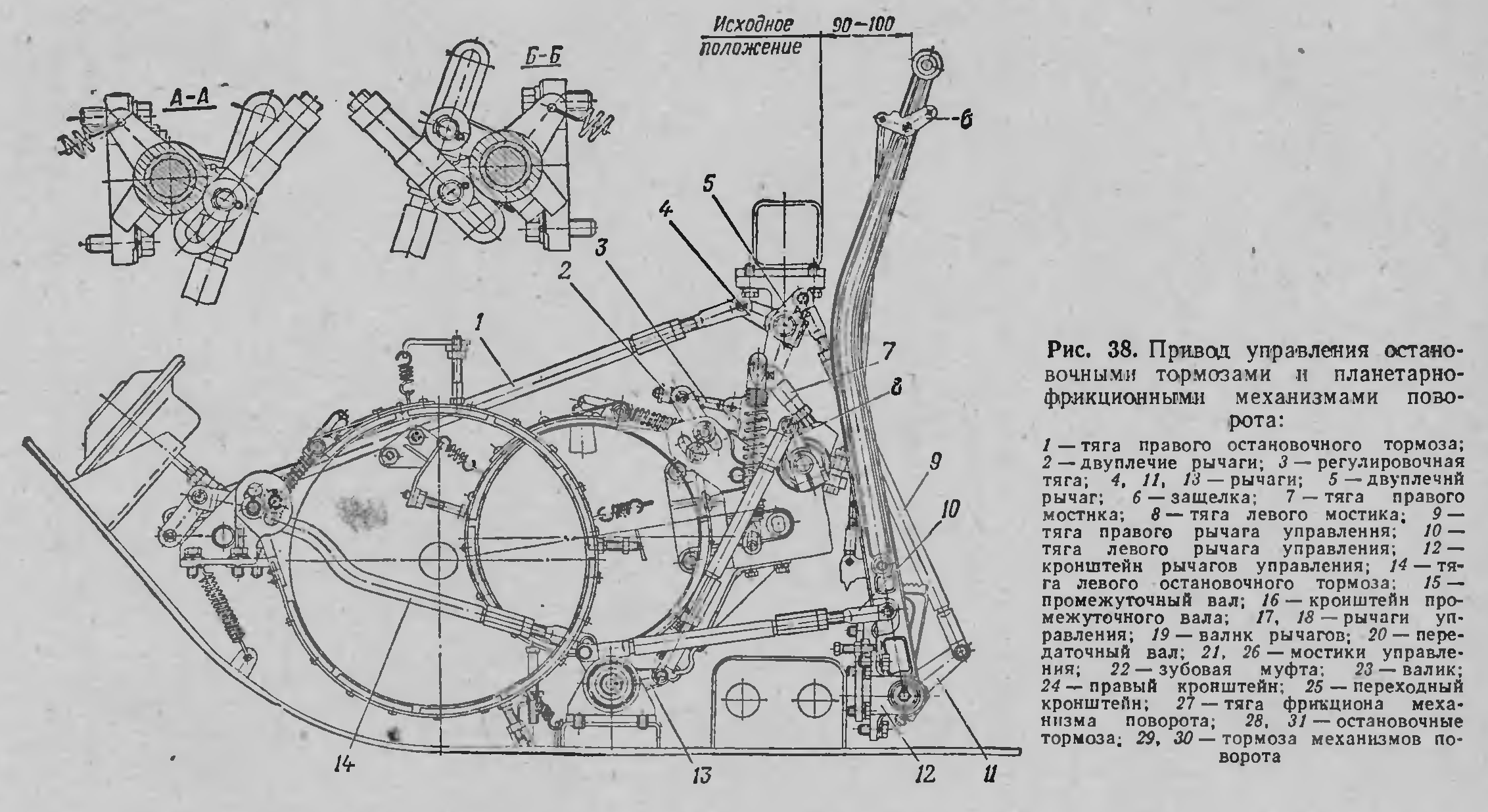
Although the weight of the MT-LB was light enough for a simple clutch-brake steering system like in the PT-76 to be viable in terms of driver fatigue, this steering system was no longer modern enough to meet demands in mobility. The main issues were that the braking losses would be high, too much speed is lost when making a turn, steering lacked precision, and a transmission with regenerative steering is essential for a vehicle intended for high speed travel in difficult terrain. Moreover, clutch-brake steering can be problematic when driving on terrain with low surface integrity, as when one track is de-clutched and braked, all of the torque from the engine is transmitted to the running track so that it outputs all of the tractive force. On swampy ground or snow, this greatly increases the risk of losing traction because the terrain cannot support high tractive force, so steering in such conditions can be ineffective, particularly in lower gears where the torque output is already high.
When the steering levers are in the initial or '0' position, the steering clutches are engaged, and the steering brakes are disengaged. In this condition, the steering inputs convey power to the steering units. In the '1' position, the steering clutch is disengaged and the steering brake is engaged. In the '2' position, the steering clutch remains disengaged, but the steering brake is disengaged, and then the stopping brake is engaged. For this behaviour to be possible, the steering clutches and brakes are regulated by a control mechanism, one for each set of steering inputs. When a steering lever is pulled back, it does not directly tighten the brake bands or pull the clutch plate, but rather, pushes upon camming surfaces under spring tension to manipulate the cranks for the clutch and brake in discrete steps. Due to the small forces involved in controlling these modules, which in turn is due to the light weight of the MT-LB, the steering levers require little effort despite the lack of power assist.
When a steering lever is being pulled to the '1' position, there is an intermediate position where the steering clutch is disengaged abruptly via the control mechanism, perceivable as a loss of spring resistance on the lever, but the steering brake band has not begun tightening. When pulled further, the steering brake is tightened by the force on the steering lever, and the lever enters position '1' when the brake is fully tightened, which is also accompanied by a loss of spring resistance on the lever. By releasing the clutch abruptly, the control mechanism prevents the clutch from slipping. This greatly extends the lifespan of the steering clutches, particularly in the hands of novice drivers. Owing to the use of a steel-on-steel clutch, even a multi-disc type, this measure to prolong the clutch lifespan was probably more important than it otherwise would be, as thin steel discs warp more readily under the heat of slippage. After the clutch is disengaged, the clutch engagement crank is unaffected by further motion of the steering lever toward the '1' and '2' positions.
When the clutch is released, the steering input ceases to transmit power, but without the application of the steering brake, the sun gear of the steering unit does not turn into a reactionary. As a result, power flow to the output axle stops, as the planetary set becomes incomplete. The power input from the ring gear only drives the free sun gear idly via the planets. This therefore de-clutches the output axle, and the track becomes unpowered. By de-clutching one track, it is possible to make the vehicle turn in a free radius. Because the track is disengaged abruptly, there is an abrupt transition into a turn, but once in the turn, the track slows down only at a gentle rate (affected by terrain resistance), so the MT-LB can be steered for small course corrections this way, even while towing a heavy load since there is no loss of engine power as the full torque of the engine is simply transmitted to the remaining powered track.
When the steering brake is fully tightened as the steering lever enters position '1', the sun gear is converted from a power input into a reactionary member. Speed summation no longer occurs in the planetary steering unit. Driven only by the ring gear, the rotational rate of the planet carrier is reduced, and the speed of the track is thereby reduced. At the rated engine speed of 2,100 RPM, this is equivalent to a loss of 4 km/h at the track. The speed difference between the two tracks initiates a turn. At low gears, the speed difference is the highest due to the large contribution of the steering input to the total axle speed, resulting in the tightest turn radius. For instance, at 2nd gear, cutting off the steering input results in a 33.3% speed reduction, whereas at 6th gear, cutting off the steering input results in only a 6.5% speed reduction. In reverse, the steering levers work in reverse. When pulling the right tiller, the right steering unit increases the reverse speed of the right track, causing the vehicle to turn to the left, and vice versa.
The track speeds at the rated engine speed of 2,100 RPM in various gears are tabulated below.
| Gear | Rated track speed (km/h) | Rated track speed without steering input (km/h) |
| 1 | 4 | - |
| 2 | 12 | 8 |
| 3 | 20.7 | 16.7 |
| 4 | 34.1 | 30.1 |
| 5 | 46.8 | 42.8 |
| 6 | 61.5 | 57.5 |
| R | 6.3 | 10.3 |
The turn radii at various gears is tabulated below. Although the steering mechanism technically provides fixed turn radii, in practice, drivers must note that due to track skid when off-roading (especially at high speeds), the turn radius may not directly correspond to the theoretical figure, normally exceeding it by some amount but never falling below it. As such, fixed turn radii figures, not just for the MT-LB but for all vehicles, tend to be described as minimums rather than being definitive figures.
| Gear | Turn Radius (meters) |
| N | 1.25 |
| 1 | 2.5 |
| 2 | 7.5 |
| 3 | 13 |
| 4 | 21.35 |
| 5 | 29.3 |
| 6 | 38.6 |
| R | 3.9 |
When a steering lever is pulled to the '2' position, the steering brake is released by a reversal crank in the control mechanism and the lever begins to tighten the stopping brake. The clutch remains disengaged. Due to the force needed to stop the vehicle without power-assisted brakes, the pulling distance for the levers to reach the '2' position is quite long, providing the necessary mechanical advantage to tighten the brake bands. It is possible to carry out a clutch-brake turn in any gear. The turn radius of a clutch-brake turn is the width between the two tracks, or 2.5 meters.
With this set of controls, the steering mechanism is able to provide a discrete turn radius in each gear and the supplementary capability of a clutch-brake turn in all gears.
It is interesting to note that, with the slow-down of the tracks when the steering levers are in the '1' position, the transmission effectively has a low-range setting, nominally doubling the number of gear settings available to the vehicle. From the perspective of automotive design, having high and low ranges was not strictly necessary, because six forward gears is sufficient for virtually all tasks that the vehicle could be expected to perform. In practice, however, the low-range mode can be used to temporarily boost traction for short periods when overcoming a serious obstacle in low gear, and it is particularly useful in this application because the relative increase in torque is significant, unlike at the higher gears where the speed reduction is relatively small and the relative increase in torque is also correspondingly smaller. One notable application for this feature is to obtain additional torque while climbing a steep and uneven hill without downshifting, which must be avoided to prevent the engine from stalling. Additional torque may be needed to overcome a rock while climbing the hill, or simply to continue climbing if the gradient of the hill increases towards its peak.
It is also worth noting that when driving this way at low gears, steering can be accomplished by either returning one steering lever to the '0' position, or pulling it further back to the '2' position to perform a clutch-brake steer. When moving across rough terrain and towing a heavy load in this condition, clutch-brake steering is preferable because the body of the vehicle acts as a second class lever, with the locked track acting as the fulcrum, the load being at the towing hitch between the two tracks, and the effort applied through the running track, which is conveying the full torque from the engine. The drawbar pull is approximately doubled in this way, helping a towed gun or trailer overcome ruts, ride over a bump while being towed uphill, or surmount some other obstacle, which generally tend to be much more challenging for a wheeled carriage than a tracked vehicle.
Unlike some differential steering systems, the transmission provides stable rectilinear motion, which is to say that it does not induce a self-steering effect when the two tracks are on surfaces with different traction characteristics. That is, differences in the moment of resistance between the left and right axles do not have any influence whatsoever on the power flow in the transmission. This characteristic is shared with the steering system of the Panther, and is due to the fact that in rectilinear motion, the transmission has only one degree of freedom, although the manner in which this was achieved is completely different. With only one degree of freedom, it was possible to avoid the self-steering effect and the loss of traction on poor surfaces. Examples of steering mechanisms with two degrees of freedom during rectilinear motion include the Merritt-Brown triple differential system of the Centurion and the Allison cross drive series, used in a wide range of tracked vehicles, including the M113. Because of this, they provide unstable rectilinear motion,
With one degree of freedom, it is impossible for the speed of either track to differ from their geared speeds, since it is impossible for the ring or sun gears of the planetary sets to change in rotational rate, as they are directly geared to the engine via fixed gears. Given that the ring and sun gears rotate at a fixed rate relative to the engine, the planets cannot rotate at any speed other than the speed imparted by the ring and sun gears (as doing so would require the teeth of the planets to intersect through the teeth of the ring and sun gears). The orbiting rate of the planets is thereby directly proportional to the ring and sun gears, and thus, the rotating rate of the output shaft is also fixed. This allows torque to be split unevenly between the two tracks. This is due to the fact that the conservation of energy also means that engine power - which is defined as energy transferred over time - is conserved. When both tracks have a speed that is fixed by the geartrain, the rotational rate is effectively constant, so the only pathway for the power to flow between the two tracks is via torque.
This ensures that if, for instance, the left track drives over a patch of ice while the right track remains on hard soil, no change in the speed of the left track occurs. In fact, due to the fixed gearing that connects the track to the engine, the track speed will not change regardless of how much or how little traction is supported by the surface, which can be very small in the case of ice, particularly if the track has already slipped and is applying traction by sliding friction rather than static friction or shear force (via grousers penetrating the ice). Moreover, all the torque available from the engine is transmitted to the ground via the track with traction, so no power is wasted. This is analogous to a car with a fixed differential. For the sake of an example: if, for instance, the engine produced 100 Nm and both axles have a direct gearing to convey 100 Nm, but the maximum reaction torque that may arise is also 100 Nm, in keeping with Newton's third law of motion. If both tracks push against the same sturdy surface, the tracks will obtain equal reaction torques, amounting to 50 Nm each and adding up to 100 Nm. Because both tracks convey a torque of 100 Nm, even if one track has lost traction completely, as long as the other has not, the track with traction will receive a reaction torque of 100 Nm and the vehicle will be propelled by the same power.
In steering mechanisms with two degrees of freedom, such as the Merritt-Brown and Cross Drive systems, there is a steering input which takes the form of a separate, independent differential drive mechanism parallel to the gearbox, connected to planetary steering units that are functionally identical to the MT-LB steering units. The steering input links the two planetary steering units, driving the sun gear while the gearbox output drives the ring gear, just like in the MT-LB. When the steering mechanism is not in use during rectilinear motion, the steering mechanism is not connected to the engine, but they still interlink the two steering units. When driving on homogeneous terrain where both tracks can receive an equal and opposite reaction force to the tractive force they transmit to the ground, both axles receive the same reaction torque from the tracks, and so the two planet carriers rotate at the same rate. However, if, say, the left track meets a patch of ice, the reaction torque at the left axle drops while the right axle has the same reaction torque, and so a torque imbalance arises in the system. This leads to the classical textbook axiom for cars with a differential - the torque available at both axles is equal to the torque at the wheel with the least traction. To express this in a more technically sound perspective, it can be said that the torque available at an axle is limited to the reaction torque obtained from the opposite axle.
From this, it is evident that any loss of tractive force from one track is also doubled by the differential, up to the extreme case where if one track loses traction completely, the entire system also loses traction completely. The large contact patch of a tracked suspension makes this scenario highly unlikely in the real world, so becoming bogged down is not such a major concern as with ordinary road cars, but nevertheless, the downside of experiencing considerable losses of traction from driving over uneven terrain with a low friction coefficient or weak integrity remains an issue. That said, although a full loss of traction at one track is not frequently encountered in real life, it can occur in extreme circumstances such as when crossing an anti-tank obstacle or overcoming a natural obstacle of similar difficulty. In this video, for example, a full loss of traction of one of the tracks and its subsequent idle winding can be seen at 7:05, 7:25 at 12:37, where the loss of traction is partly due to the loss contact with the ground over most of the contact patch.
This steering mechanism provides regenerative steering - that is, recuperation of the power from the inside track by transferring it to the outside track. This preserves the thrust-to-weight ratio of the machine in a turn. For comparison, the crossdrive hydromechanical transmission in M113 APCs provided regenerative steering with infinite turn radii by smoothly varying the position of the steering levers, achieved by slipping a left or right steering clutch in the steering differential, but had no ability to neutral steer.
Overall, having a discrete turn radius in each gear, the option of a clutch-brake turn in all gears, and easy gear shifting with a synchronized gearbox can be considered sufficient for an MT-LB to realize the full potential of its engine power and give drivers more confidence on rugged terrain. The provision of neutral steering may be credited as a positive point as well, but on poor terrain, where the MT-LB is most attuned to operate, the risk of throwing a track when performing neutral turns - particularly for vehicles with a relatively long ground contact length such as the MT-LB - means that the usefulness of this feature is rather uncertain.
BRAKES
The stopping brakes are band brakes. The stopping brake mechanism is very similar to the steering brake mechanism, but larger in diameter for the large stopping brake rotor (330mm vs 250mm). They serve as steering brakes in the transmission's clutch-brake steering mode, as service brakes and as parking brakes. The only way to mechanically engage the brake is with the steering tillers. To provide sufficient braking force to stop the vehicle even at high speeds, a diaphragm-type pneumatic braking actuator was fitted parallel to the brake band tightening mechanism on each side, activated by the brake pedal; the brake pedal has no mechanical connection to the brake mechanism whatsoever. The circular diaphragm braking actuators are depicted by dashed outlines in the drawing below.

The brake pedal controls the valve system to the pneumatic actuators on both brakes, and the steering levers control the band tightening mechanism by control rods. Diaphragm-type actuators are often favoured for this application because a diaphragm allows reliable sealing of the air chamber, provides a high push force, and the limited range of motion of the diaphragm is sufficient for brakes.

The pneumatic braking mechanism allows the driver to precisely control the braking force by controlling the pressure within the brake actuator with the deflection angle of the brake pedal. To provide consistent feedback to the driver, the mechanism functions in such a way that the pedal resistance is consistent to the pedal deflection angle regardless of the available air pressure, although it cannot ensure that the braking force is unchanged, as that depends on whether the pneumatic system of the MT-LB is operating at normal parameters. However, with this braking configuration, drivers must be aware that in the event of a pneumatic system failure and emergency stopping is needed, the brake pedal cannot be used and that instead, the driver must use the tillers.
A ram-air intake on the transmission compartment access panel allows cool air to enter and circulate inside the compartment, primarily for the sake of cooling the service brakes. There are no outlet vents near the service brakes to induce a draft across the brake rotors, and the central location of the ram-air intake does not facilitate good airflow over the brakes, especially since the intake is shaped to direct the incoming air directly downwards. The gearbox itself does not greatly benefit from this rudimentary method of air cooling, as it already has its own oil cooler. The intake can be opened and closed from the crew compartment with a push-pull handle. When closed, it is watertight enough to not pose an issue when the vehicle is swimming.
FINAL DRIVES
The use of a planetary final drive was commensurate with the role of the MT-LB as a prime mover, but like the steering units, the planetary gear set includes only one planet. To provide the necessary gear strength to handle the torque of the engine, multiplied by the gearbox, the planet has a large face width and tooth thickness. The sun gear delivers the output from the gearbox, the planet carrier is the axle of the drive sprocket, and the final drive housing itself serves as the reactionary ring gear.

In general, the torque rating of final drives is designed according to the maximum torque flowing through the overtaking track when it is turning the vehicle uphill at the maximum specified roll angle. In this condition, when steering normally, regenerative torque from the lagging track increases the tractive force at the overtaking track, placing it under increased stress due to the high cumulative load. The final drive is maximally stressed in the case of a clutch-brake turn, where the overtaking track is conveying the entire torque output of the engine. For a prime mover intended for the role of a tractor-transporter, an intrinsically strong final drive was necessary, since the load on the drivetrain tends to be particularly large from a combination of a towed load and onboard cargo. This is distinct from tracked vehicles such as tanks, which are not specified to carry any cargo beyond its own combat load, and are only permitted to tow other tanks over relatively gentle terrain. As such, the use of a single-planet planetary final drive instead of a typical set of three is very unusual, as load distribution would be desirable for a large safety margin, even if a single planet was technically sufficient.
SUSPENSION

Contrary to expectations with the high power-to-weight ratio and good transmission characteristics, the design of the suspension was somewhat dated. It consists of six roadwheels on each side, with torsion bar suspension and an unsupported track. The first and last roadwheel on each side has a shock absorber and volute spring bump stop. To reach the bump stops, the first and last roadwheel swing arms have a protruding arm. Single-pin tracks are used.
Trailing swing arms are used for all roadwheel pairs except the last, which have leading swing arms, creating a zone with an enlarged open floor area in the cargo compartment. This zone does not actually free up any height for larger cargo because the space is bisected by a reinforcing beam, and the maximum size of cargo is limited by the small rear doors regardless. Rather, this feature of the suspension was merely a holdover from the MT-L, which used the open floor area for more convenient placement of its floor fuel tanks that were additionally closed off by load-bearing floor panels for supporting cargo.
The use of unsupported track could be considered the primary distinguishing feature of the MT-LB suspension against the backdrop of the myriad of very similar suspensions on other Soviet light tracked vehicles. The disadvantages of an unsupported track are that it tends to impart greater dynamic loads on the engine due to tension fluctuations, and the tracks can be thrown against the sponsons during high-speed off-road driving can be violent enough to slap the sponsons, leading to damage and noise.
The suspension of the MT-LB is visually and structurally very similar to the suspension of the PT-76, mainly down to the most obvious details such as the number of roadwheels. This has led to the misconception that the suspension is the same, or that the MT-LB itself was derived from the PT-76, but in fact, the suspension was a separate design that simply shared the same basic primary characteristics. The parts for the suspension are all proprietary, bearing product indices, and there is no direct interchangeability with the PT-76. Structurally, the most obvious difference was that the MT-LB used different shock absorbers, a different tensioning mechanism on its idler wheels, and it had full-length torsion bars that span the entire width of the hull, whereas the PT-76 used torsion bars that were a few inches short of the full width of the hull.
The torsion bars have a diameter of 36mm. Each bar weighs 17.68 kg.
Front mudguards are fitted as standard, but the MT-LB suspension did not have any form of dust or mud splash suppression other than the hydrodynamic paneling kit for amphibious operations.
The roadwheels are 670mm in diameter. The axle hub is a casting of AMG6 grade aluminium, onto which a pair of stamped aluminium discs are welded which are then closed with a welded rim to form a watertight hollow cavity, thus forming the wheel. A rubber rim, 112mm wide, is then bonded on. 38KhS grade steel wear rings are screwed to the rim, acting as sacrificial elements to rub against the guide horns of the track when the vehicle is in motion, eliminating wear on the aluminium wheel itself. The hollow cavity in the discs provide additional buoyancy when swimming. This was an old and well-established design practice by this point in the history of Soviet light tracked prime mover production, with hollow wheels present even on vehicles not designed to swim, including the AT-P, the predecessor of the MT-LB.

A pair of roller bearings are fitted to each wheel and the outer end is sealed with a hubcap while the inner end, connected to the swing arm, is sealed with a labyrinth seal. Each wheel weighs 43.42 kg, which is slightly heavier than a 41.09 kg roadwheel from a BMP-1, but indicates that it is proportionately very similar to the BMP roadwheel in the sturdiness of its construction, considering that the BMP roadwheel diameter is only 600mm. The ball bearings are lubricated with grease, which is unsurprising as it was the chosen solution on the great majority of Soviet tracked vehicles. The swing arms on each roadwheel are fitted with textolite bushings for vibration damping.
The table below lists the axle load on each suspension unit for the MT-LB. The axle loads will be the same for the MT-LBV, because the tracks, although heavier, are an unsprung mass. According to the article "Метод Анализа Компоновочных Схем И Параметров Вгм, Создаваемых На Базе Многоцелевого Гусеничного-Шасси", published in the 1977 No. 2 issue of the "Вестник Бронетанковой Техники" journal, the maximum permissible load on the rim of a roadwheel is 1,100 kgf. As mentioned in the "Cargo" section, this most likely refers to the maximum average load on a roadwheel, considering a distributed weight of 13.2 tons over twelve suspension units, taking into account that while the middle roadwheels bear the highest static loading, the front and rear roadwheels bear the strongest dynamic loads and are the most stressed overall.
| Roadwheel | Axle load (empty vehicle) | Axle load (loaded to 10.3 tons) |
| 1 | 960 | 780 |
| 2 | 810 | 865 |
| 3 | 723 | 930 |
| 4 | 632 | 855 |
| 5 | 540 | 885 |
| 6 | 457 | 910 |
Owing to the lack of a counterbalance to the weight of the transmission and engine when the MT-LB is not carrying cargo, the front roadwheels, particularly the first roadwheel pair, are much more heavily loaded relative to the rest of the roadwheels when the vehicle is empty. Relative to the third roadwheel when the vehicle is lightly loaded, the peak load on the first roadwheel pair is not particularly high, which presumably explains why the first suspension pair did not require special reinforcement. However, considering that the load limit on each roadwheel is 1,100 kgf, the roadwheels are apparently working near their limit at all times.
A highly noteworthy trait of the MT-LB suspension is that, aside from the first and last units, none of the suspension units have a hard stop. This generally implies that, if the vehicle is somehow falls onto a sturdy protruding obstacle such as a tree stump or a large boulder the size of a small boulder, some of the wheels may be deflected far enough to break their torsion bars, particularly the middle wheels. According to experienced MT-LB drivers, the suspension is capable of supporting the weight of a loaded vehicle with only the middle wheels resting on a tree stump, indicating that the range of motion is large enough, and the vehicle light enough, that the lack of hard stops does not pose issues in everyday use.
Another interesting feature of the suspension unit is that the swing arm length and wheel diameter coincided in such a way that it is possible for a torsion bar swap to be carried out without removing the wheel, which is a relatively uncommon feature for tracked vehicles. This is largely due to the long swing arms, even relative to the roadwheel diameter.

The idler wheel is 510mm in diameter, and its design is somewhat uncommon in that its two discs are very narrow. A somewhat unusual feature of the idler is that the idler wheel adjustment mechanism is inside the cargo compartment, rather than outside the hull. The mechanism does not make use of a worm gear, instead having a screw to raise or lower the inner end of the swing arm where a tensioner arm is splined to the swing arm axle, thereby lowering or raising the idler wheel at the other end. To adjust the tension, the nut on top of the tensioning screw, marked (11) in the diagram below, is twisted with a wrench to turn the tensioning screw (after a retention cap over the nut is released). Once the idler wheel has been lowered to the maximum extent, the tensioner arm (17) will rest against the top of the frame, and the tensioning screw (18) will not be able to raise it any further. Further twisting the nut will unscrew the tensioning screw, to the point where it can be entirely removed from the tensioning mechanism. The tensioner arm and the tensioner screw alone are shown together in this image.


In the article "Отечественные гусеничные транспортеры" published in the February 2015 issue of the "Техника и вооружение" magazine, it is claimed that the design of the idler wheel, consisting of two thin discs, works to break up ice on the tracks.
The drive sprocket is 604mm in diameter, with a pitch diameter of 530mm.
Two types of single-pin tracks are available for the MT-LB, an open-joint all-metal type, or OMSh (below, left), and a closed type with a rubber bushing, or RMSh (below, right). The ground contact length is 3.7 meters regardless of the tracks used (the distance between the axis of the drive sprocket and the idler wheel is 5,125mm). This is substantially more than similar vehicles like the M113 (2.67 m) on account of the longer, squatter hull of the MT-LB. This, of course, also amounts to an increase in the weight of the tracks and the rotating mass of the suspension system, while also leading to an increased turning resistance.


The width of the OMSh tracks is 350mm, and the track pitch is 111mm. The design of the tracks is very similar to the tracks of the AT-L, although it is wider by 50mm and has a smaller pitch. The track links are cast Hadfield steel. The nominal service life of the tracks is 3,000 km. To improve traction on snow and swampy ground, the track surface was designed with aggressive grousers. The RMSh tracks have the same width but a slightly shorter pitch. The exact pitch length is unknown, as is the service life of the track.
With a set of new OMSh tracks, there would be 108 track links on each side, whereas with the RMSh tracks, there would be 122 track links on each side. A set of OMSh tracks weighs 693.91 kg, and a set of RMSh tracks weighs 885.7 kg. With OMSh tracks, the tracks weigh 13.7% of the vehicle weight (based on curb weight) and with RMSh tracks, 17.5% of the vehicle weight. This is quite high for a lightly armoured vehicle, but is largely due to the low curb weight of the MT-LB, being a transporter without a serious weapons module. For comparison, one set of tracks for a BMP-1 weighs 625 kg, but the BMP-1 weighs 12.6 tons combat loaded, giving a proportional track weight of just 10%. With a fully loaded MT-LB, the proportional weight of its tracks falls much closer to this figure.
With RMSh tracks, the shorter pitch leads to some increase in the mean maximum pressure (MMP) exerted by the MT-LB on top of its added rotating mass, owing to the smaller area of the track links. For a tracked suspension, the traction developed is not constant across the length of the ground contact patch, but varies by the load on each roadwheel, the area of the track link(s) directly underneath the roadwheel bearing the load, and the track tension available to distribute the load between the track links. With a shorter pitch, this meant that the RMSh track must increase the MMP of the MT-LB, although to an unknown extent, and driving performance on soft terrain can be expected to have worsened.
However, the RMSh track is more durable, immune to accelerated track pin wear when driving on sandy terrain, has favourable winding characteristics, generates less noise and vibration owing to its shorter pitch, and permits the vehicle to reach a high speed much more easily. Its added rotating mass is compensated by the reduction in rolling resistance, which is significant and is responsible for making the RMSh type more suitable for travelling at higher speeds.
On the MT-LBV, OMSh tracks with increased width were fitted, accompanied by wider fenders. The new 560mm-wide tracks greatly enhanced mobility in particularly harsh terrain, such as on thin ice, on marshy ground or on deep snow. However, with a total weight of over 2 tons for a set of two tracks, they added a great deal of rotating mass to the suspension. Their design structurally incorporated duckbill extensions and also added small extensions on the inner side of the track to further increase the ground contact area. These tracks are of the OMSh type and have the same pitch as the standard OMSh track, and as such, 108 links are needed per side. They can be used on vehicles with drive sprockets meant for the standard OMSh track, and the same number of links per side is used.

With the wider and heavier track, the MT-LBV is also capable of a higher drawbar pull due to the increased tractive force it can put out, especially in softer terrain where the larger area of grousers available on the track distributes traction across a larger soil area, reducing shear stress and thus increasing the obtainable soil thrust.
All three types of track have mounting holes for cleats, which are an optional accessory for use on very slippery terrain. Each cleat is individually fitted, two on each track link. It is not recommended to drive above 3rd gear when using these cleats, or drive further than 6-8 km at a time. As such, they are meant for temporary use, limited to helping when carefully crossing regions of difficult terrain at low speed, after which they should be removed when more robush paths are available. They are not comparable in purpose to the optional grousers fitted in place of the rubber track pads on many American and German tank tracks.

With the standard tracks, the MT-LB exerts a nominal ground pressure of 0.443 kgf/sq.cm when loaded with the maximum rated onboard cargo of 2.5 tons. This is considerably lower than the ground pressure of a standing infantryman, and also much lower than the 0.549 kgf/sq.cm ground pressure of the M113A1, measured based on its combat weight according to technical manual TM-55-2350-224-14. As another point of comparison, the gground pressure of the BMP-1 is 0.6 kgf/sq.cm.
Thanks to its wider tracks, the MT-LBV exerts a nominal ground pressure of only 0.244 kgf/sq.cm at its curb weight or 0.28 kgf/sq.cm when loaded with a crew and 1.5 tons of cargo - two times lower than that exerted by a standing infantryman and equivalent to the loaded ground pressure exerted by the much larger DT-10 and DT-30 series articulated all-terrain vehicles when loaded to their rated cargo of 10 and 30 tons respectively. This gives it excellent terrain-crossing abilities across most landscapes. However, while excellent for a conventional all-purpose armoured military vehicle, this is still incomparable to specialized vehicles such as the Bv 206, which has a limiting ground pressure of 0.13 kgf/sq.cm - less than half that of the MT-LBV.
Thanks to the flotation of the wider track, MT-LBVs are capable of being regularly driven in seemingly impassable terrain, such as shown in the image below purportedly showing a driving course for training MT-LBV drivers.

The added weight of the tracks would not have a negative effect on the traction of the vehicle, as the greater weight pressing upon the ground will increase the friction force. Even so, the MT-LBV was rated for a much smaller towed load than the MT-LB for unknown reasons.
By calculating the weights of the individual suspension elements, including tracks, idler and drive sprockets, complete wheels, swing arms, torsion bars, mud scrapers, hydraulic shock absorbers, but excluding the volute spring bump stops, the total weight of the suspension is no less than 2,631.39 kg with OSh tracks, or 3,014.97 kg with RMSh tracks.
WATER OBSTACLES
The MT-LB is readily amphibious. Because the engine and transmission are at the front of the hull, it was not feasible to implement water jets for propulsion in water. Instead, the MT-LB is propelled by its tracks. Special hydrodynamic grilles are fitted behind the idlers at the rear of the hull to enhance the directivity of the flowing water around the tracks, and special panels are installed around the front of the hull to prevent water from flowing forward. When not in use, this equipment is carried externally on special stowage points with straps. When swimming, the metacentric height of the vehicle is 0.5 meters, and the minimum reserve buoyancy is 20%, which is met when the vehicle is loaded with 2 tons. The maximum immersion depth of the hull is 0.3 meters to its roof.To prepare for crossing water obstacles, the wave breaker is raised, the shielded air intake tube is fitted over the air intake if it was not already fitted, a splash guard is fitted over the radiator and exhaust outlets, fender panels are installed around the drive sprockets, and the rear hydrodynamic grilles are lowered and clamped in place. For an MT-LBV, the wider tracks required wider fender panels and rear hydrodynamic grilles. The specified preparation time for a water crossing operation by swimming is 20 minutes.

Forward propulsion is provided by the rearward flow of water dragged by the retreating run (the lower run) of the tracks. The efficiency of the track in ploughing water rearward is quite low, so the rear hydrodynamic grilles were made to increase the directivity of the rearward flow of water. The grilles work by receiving the upward flow of water from the rear sloping part of the retreating run, and redirecting it rearward. The flat-faced front fender panels have the opposite function, working to sharply reduce the efficiency of the returning run (top run) of the tracks in ploughing water forward. An MT-LB fitted with these panels is shown in the images below, courtesy of Monk of War.


Without the panels around the drive sprockets, the efficacy of water jet propulsion is significantly reduced, because the forward flow of water dragged by the returning run of the track neutralizes the forward thrust from the rearward flow of water dragged by the retreating run of the track, leaving the redirected flow of water through the hydrodynamic grilles as the only source of forward propulsion.

The lower half of each of the grilles is shaped to direct water inward. When both tracks are running, the opposing inward flows from both tracks eliminates any turning effect. When one track is stopped, the inward flow from the opposite track increases the turning force, enabling the vehicle to turn more tightly than if it only had a direct rearward flow from one track.

The top speed achieved while swimming with a nominal cargo load (presumably 2 tons) is 5-6 km/h. The top speed in reverse is unspecified. The vehicle can be driven into a water obstacle at a downhill slope of 20 degrees, but exit at an uphill slope of no more than 15 degrees.
Like all other amphibious Soviet vehicles, the MT-LB features a bilge pump to bail water out of the hull. According to the article "Универсальный Солдат Многоцелевой Транспортер-Тягач МТ-ЛБ", when the bilge pump is running, the MT-LB can allegedly be kept afloat with a loss of buoyancy of up to 30%, although the author does not specify what a "loss of buoyancy" means.
The permissible wave height when swimming is 0.5 meters, but when fording a water obstacle, it is only 0.15 meters, probably due to concerns of water ingress when the vehicle is not prepared for swimming. Splash protection when swimming is provided by the shielded air intake tube and the boxy splash guard over the radiator and exhaust outlets.


As an aside, it is interesting to note that the plugs for the drainage holes were borrowed from the BTR-60 series or at least were of the same standard design. In the BTR-60, these plugs were not simply drainage plugs as they are on the MT-LB, but were made to drain water from various points in the hull into the intake ducts of the bilge pump, which is why they were designed to be open from the inside and have a twist handle to screw the stopper. The intake ducts of the bilge pump were of the same thickness of the BTR hull belly, mitigating the vulnerability posed by the exposed drainage holes. In the MT-LB, the stoppers are the only sealing element to plug the drainage holes in the hull belly.


Owing to the location of three of these drainage holes near the right and left ends of the hull, there can be a noticeable weakening of the belly to heavy anti-personnel mines detonating under the nearside edge of the tracks. The location of all drainage holes is shown in the drawing below, but the sizes are greatly exaggerated and the positioning is inexact. For instance, one of the drainage holes marked in the drawing below (11) is actually located right up against the side hull wall, as the image on the right above shows.