
The T-72 is known as one of the most numerous tanks in the world today, and the tank is likely to remain in some form of service for the rest of the 21st Century, so before we examine the history of the T-72, let us see how many of these tanks were actually built. A few years ago, Uralvagonzavod (UVZ) made efforts to declassify much of the history of the T-72 tank, including the number of tanks built by the factory. The table below comes from the factory archives of UVZ, published in the book "T-72/T-90: The Experience of Creating Domestic Main Battle Tanks" authored by S. Ustmantsev and D. Komalkov (head designer of the UVZ transport engineering bureau).

From 1973 to 1990, a total of 18,373 T-72 tanks and T-72 derivatives were manufactured at the UVZ factory floor and another 1,600 tanks were manufactured from 1991 to 1996. The Chelyabinsk Tractor Factory also took part in the manufacture of the T-72 tank, producing 1,894 units themselves between 1978 and 1990. In total, 20,267 T-72 tanks were produced in Soviet Russia, making it the second most numerous tank ever produced in both the USSR and the world, outstripping the T-62 for that title by a slim margin. Of that total, 5,264 T-72A tanks were delivered to the Soviet Army. But how did it come about? The 2010 book "T-72 Ural armor versus NATO" by noted military historian Mikhail Baryatinsky details the history of the development of the tank, and is the source for many of the diagrams and pictures shared below.
Firstly, it should be clear that the T-72 is indeed a "mobilization model" of a sort with slightly inferior performance compared to the later models of the T-64 series. The main factor that relegates the T-72 to this category during its service career in the Soviet Army was its role as the primary tank model for motorized infantry units and other mainline Army units whereas the T-64 and T-80 series tended to be supplied to Guards units. The T-72 was also widely exported during the Cold War, and as such, the T-72 could be rightfully considered the backbone of the Soviet Army and that of many other nations together with the T-55 and the T-62. With that said, some Internet sleuths found this chart of procurement prices showing that the T-72A (1979) was significantly more expensive than the T-64A. The more expensive pricing of the T-72 does not change the fact that it was a less sophisticated product compared to the later models of the T-64 such as the T-64B, although it was not originally intended to be such by the chief designer of the UKBTM design bureau, Leonid Kartsev. In fact, the original T-72 outpaced the T-64A in some technical areas due to the implementation of certain technologies.
Let us take a look at the Object 167M. It is a precursor to the T-72, but is better described as a T-62 taken to the extreme.

The Object 167M featured the now-famous AZ autoloader, composite armour for the upper glacis and turret, a 125mm D-81T cannon, a V-26 engine which developed 700 HP, a reinforced transmission to deal with the increased power, hydraulically powered gear shifting systems, the new "Liveni" two-plane stabilizer system, and a new suspension composed of six roadwheels with three return rollers. The tank did not enter mass production because the Object 432 had already been ordered to enter production as the T-64 by a resolution from the Council of Ministers of the USSR and the Object 167M had numerous drawbacks of its own. In February 26, 1964, the scientific-technical council GKOT examined the Object 167M project and rejected it. This was the end of the road for the Object 167M, but it was destined to leave its mark on Soviet tank history, as we shall see later on.
The Minister of Defence Industry S.A Zverev came to the experimental workshop of the Uralvagonzavod factory on October 26, 1967, the 50th anniversary of the October Revolution. After an invitation to enter and examine a modified T-62 with a 125mm gun (a special development in response to Kharkov's failure to begin mass production of the T-64 on schedule) by UKBTM design bureau chief Leonid Kartsev, the minister requested a demonstration. The designer E.E Krivosheya and researcher L.F Terlikov who were loitering around the tank quickly joined the two inside, started it up and activated the autoloader. The minister was impressed by the autoloader and was enthusiastic on the idea of putting it in the T-64, but rejected Kartsev's proposal to also replace the 5TDF engine on the T-64A with a supercharged derivative of the V-2 engine (from the T-34) developed in Chelyabinsk. He only agreed on changing the engine on the next day after a private meeting with the head of the Military Industrial Commission I.V Okunev. It was agreed that six T-64A tanks were to be sent to UVZ to be given the modifications specified by Kartsev, but the minister also dictated that the suspension and chassis were to be untouched. On 5 January, 1968, Zverev officially gave the order to begin the "modernization" of the T-64A by the Uralvagonzavod factory. Thus the life of the T-72 began, but for the next few years, all prototypes of Kartsev's new tanks would either be modifications of these six T-64A tanks or modified copies thereof.
The first of these modifications, dubbed "Object 172", was completed in the summer of 1968, and the second was completed in September of that same year. The Object 172 differed from the T-64A obr. 196 in the fighting compartment which had to be rearranged to fit the new autoloader, and in the engine compartment which was completely reworked for the V-45K engine and T-54-style cooling system.
Because the modifications were focused only on internal components and the engine compartment, the Object 172 was practically indistinguishable from a typical T-64A obr. 1989 from the front, but from the rear, the turret was clearly modified for the autoloader's ramming and ejection system, while the engine deck was completely distinct from that of the T-64 series. The engine compartment itself was also lengthened to accommodate the new powertrain and cooling system, so the tank is not as compact as the T-64 in length. The left side of the hull gained an exhaust port just above the second rearmost roadwheel - a location reminiscent of the earlier T-54 and T-62.

Baryatinsky's book gives us the details of the late stages of gestation of the T-72. Here are a few translated paragraphs:
"... in the Design Bureau of the UVZ, which since August 1969 was headed by V.N. Venediktov, it was decided to use the chassis of the Object 167 with rubberized roadwheels of increased diameter and more durable tracks with open metal track pins [author's note: OMSh] similar to those of the T-62 tank. The development of this tank was carried out under the designation "Object 172M". The engine, boosted to 780 hp, received the index of V-46. A two-stage air-cleaning cassette system was introduced, similar to that used on the T-62 tank. The weight of the Object 172M increased to 41 tons, but the mobility characteristics remained at the same level due to the increase in engine power by 80 hp, the capacity of fuel tanks by 100 liters and the width of the track by 40 mm.
From November 1970 to April 1971, Object 172M passed a full cycle of factory tests and then on the 6th of May 1971, it was presented to the Minister of Defence A.A. Grechko and to the Minister of Defence Industry SA. Zverev. By the beginning of the summer, a test lot was created from 15 vehicles, which, together with the T-64A and T-80 tanks, passed many months of testing of an unprecedented scale. At the suggestion of Major-General Yuri M. Potapov, a battalion composed of three companies with tank platoons was formed. Each company was formed from tanks of the same type. The route of the traffic was chosen from Dnepropetrovsk through Ukraine to Belorussia to Slutsk and then back to Dnepropetrovsk, and then through the Donbass and the North Caucasus to Baku, across the sea by ferry to Krasnovodsk, through the Karakum desert and the Kopetdag mountain range. The tests were due to be completed at a range, 60 km from Ashgabat. During the march, live firing tests were conducted at various firing ranges, and platoon and company level exercises with live firing and maneuvering were carried out at various tankodroms [author's note: training grounds].
After the end of the tests, a report with the title "Report on the results of military trials of 15 tanks 172M, manufactured by Uralvagonzavod in 1972" was submitted. The final part of the report contained these remarks:
In accordance with the decision of the Central Committee of the CPSU and the Council of Ministers of the USSR of August 7, 1973, Object 172M was adopted by the Soviet Army under the name of T-72 "Ural". The official order of the Minister of Defense of the USSR was published on August 13, 1973. In the same year, a pilot batch of 30 tanks was produced at Uralvagonzavod."
And thus, the T-72 was born. An amalgamation of the T-64A and the Object 167M, the T-72 would go on to become the second most widely produced tank in the world, behind only the T-54.

In the end, the T-72 was similar enough to the T-64 that it was not easy to tell them apart at first glance, yet different enough that there was virtually no commonality in parts between the two tank families. This was one of the many headaches caused by the rivalries in the Soviet tank building industry, but still, this did not change the fact that the T-72 was an extremely capable tank. When viewed in terms of cost efficiency, the T-72 was second to none during its heyday and still remains a relatively competitive product to this day if given sufficient upgrades.
Although many T-72 models could be considered technically inferior to a T-64 or T-80 counterpart from the same period, the difference in combat capabilities was generally quite small. According to captured Soviet documentation from 1977 presented in this CIA report, the combat potential coefficient of the T-64A is 1.50 and the T-72 is rated at 1.50. Thus, the T-72 was considered to be the equal of the T-64A during the earlier years of its life. However, the gap in capabilities appears to widen as the years go by: the combat potential of the T-64B is rated at 2.10 and the "T-72 with TPD-K1" is rated at only 1.70. However, the T-72A (1979) did not yet exist by the time the document was published (1977) whereas the T-64B (1976) was already in mass production, so it is not so easy to directly compare the T-64B with the closest T-72 counterpart. Generally speaking, however, the determining factor appears to be in the fire control system. Indeed, the inclusion of the TPD-K1 laser rangefinding sight alone apparently gave the T-72 a 0.2 point advantage over the basic model. The additional advantages enjoyed by the T-64B included the ability to fire guided missiles which the T-72 family lacked until 1985 when the T-72B began mass production. The T-72 series also retained the same TPD-K1 sight in one form or another throughout its career in the 80's and into modern times. On the other hand, the T-64A began with the TPD-2-49 sight in 1972 which the T-72 Ural shared, but the T-64 was upgraded to the T-64B variant and was equipped with the substantially more advanced 1A33 sighting complex with the 1G42 sight in 1976 and retained it until 1987 when the T-64 family was discontinued altogether. However, the cost efficiency of the T-72 was a different matter.
In the book "Combat Vehicles of Uralvagonzavod: T-72 Tank" published by the Information and PR department of Uralvagonzavod, it is claimed that the money spent on purchasing a single T-80U could otherwise be invested in three T-72Bs (with an additional 16,000 Rubles), so in other words, the funds required to purchase two T-80U tanks could cover the cost of a platoon of T-72B tanks as well as a moderate supply of spares. One may be reminded of the stereotype of the Soviet Army favouring hordes of inferior tanks instead of a numerically small collection of technically superior ones, but this is simply not the case. Having a large number of tanks is necessary to ensure that tank support is regularly available to the infantry and there must be enough tanks to fulfill certain operational and strategic objectives, including having enough reserves to support and consolidate territorial gains.
Referring to the theory of cost efficiency detailed in the book "Tanks: Tactics, Technology, Armament" by Yu.P Kostenko, the Uralvagonzavod editors claim that the calculated cost efficiency coefficient of the T-72B is 3.38 whereas the calculated cost efficiency coefficient of the T-80U is only 1.25. Theoretically, the cost efficiency of the T-72B is 2.7 times higher. The method by which combat effectiveness is quantified is a complex affair so it is difficult to independently verify these numbers using third party (i.e non-UVZ) primary sources, but this is merely academic. The high cost effectiveness of the T-72 undoubtedly had a large influence on the monumental export success of the tank, especially considering that the core customer base for Soviet and Russian arms are Second World or Third World nations that typically do not have a large procurement budget and want the maximum return on their investment.
Furthermore, Kostenko writes in his 2001 monograph "Tank: Man, Environment, Machine" that the time needed for maintenance after 350 km of operation in a T-72B corresponds to 200 km of operation for a T-64B and 100 km of operation for a T-80B. In other words, the amount of maintenance required for a T-72B for any given unit of distance is 3.5 times less than a T-80B and 1.75 times less than a T-64B.

But before we take a look at the T-72 in earnest, we must first remember that the original Ural variant underwent several major upgrades throughout its lifetime, creating significant discrepancies between each successive model. To complicate matters, each model in itself may have subtle improvements implemented during overhauls. For example, the transition from the T-72 Ural to the T-72A was gradual, with many of the changes embodied by the so-called "Ural-1" model that contained a mixture of features from both the T-72 Ural and the T-72A. The T-72 Ural-1 entered service in 1975-1976, depending on the source. Russian historian A.V. Karpenko states that this modification was accepted into service in 1975.
From 1973 to 1990, a total of 18,373 T-72 tanks and T-72 derivatives were manufactured at the UVZ factory floor and another 1,600 tanks were manufactured from 1991 to 1996. The Chelyabinsk Tractor Factory also took part in the manufacture of the T-72 tank, producing 1,894 units themselves between 1978 and 1990. In total, 20,267 T-72 tanks were produced in Soviet Russia, making it the second most numerous tank ever produced in both the USSR and the world, outstripping the T-62 for that title by a slim margin. Of that total, 5,264 T-72A tanks were delivered to the Soviet Army. But how did it come about? The 2010 book "T-72 Ural armor versus NATO" by noted military historian Mikhail Baryatinsky details the history of the development of the tank, and is the source for many of the diagrams and pictures shared below.
Firstly, it should be clear that the T-72 is indeed a "mobilization model" of a sort with slightly inferior performance compared to the later models of the T-64 series. The main factor that relegates the T-72 to this category during its service career in the Soviet Army was its role as the primary tank model for motorized infantry units and other mainline Army units whereas the T-64 and T-80 series tended to be supplied to Guards units. The T-72 was also widely exported during the Cold War, and as such, the T-72 could be rightfully considered the backbone of the Soviet Army and that of many other nations together with the T-55 and the T-62. With that said, some Internet sleuths found this chart of procurement prices showing that the T-72A (1979) was significantly more expensive than the T-64A. The more expensive pricing of the T-72 does not change the fact that it was a less sophisticated product compared to the later models of the T-64 such as the T-64B, although it was not originally intended to be such by the chief designer of the UKBTM design bureau, Leonid Kartsev. In fact, the original T-72 outpaced the T-64A in some technical areas due to the implementation of certain technologies.
Let us take a look at the Object 167M. It is a precursor to the T-72, but is better described as a T-62 taken to the extreme.

The Object 167M featured the now-famous AZ autoloader, composite armour for the upper glacis and turret, a 125mm D-81T cannon, a V-26 engine which developed 700 HP, a reinforced transmission to deal with the increased power, hydraulically powered gear shifting systems, the new "Liveni" two-plane stabilizer system, and a new suspension composed of six roadwheels with three return rollers. The tank did not enter mass production because the Object 432 had already been ordered to enter production as the T-64 by a resolution from the Council of Ministers of the USSR and the Object 167M had numerous drawbacks of its own. In February 26, 1964, the scientific-technical council GKOT examined the Object 167M project and rejected it. This was the end of the road for the Object 167M, but it was destined to leave its mark on Soviet tank history, as we shall see later on.
The Minister of Defence Industry S.A Zverev came to the experimental workshop of the Uralvagonzavod factory on October 26, 1967, the 50th anniversary of the October Revolution. After an invitation to enter and examine a modified T-62 with a 125mm gun (a special development in response to Kharkov's failure to begin mass production of the T-64 on schedule) by UKBTM design bureau chief Leonid Kartsev, the minister requested a demonstration. The designer E.E Krivosheya and researcher L.F Terlikov who were loitering around the tank quickly joined the two inside, started it up and activated the autoloader. The minister was impressed by the autoloader and was enthusiastic on the idea of putting it in the T-64, but rejected Kartsev's proposal to also replace the 5TDF engine on the T-64A with a supercharged derivative of the V-2 engine (from the T-34) developed in Chelyabinsk. He only agreed on changing the engine on the next day after a private meeting with the head of the Military Industrial Commission I.V Okunev. It was agreed that six T-64A tanks were to be sent to UVZ to be given the modifications specified by Kartsev, but the minister also dictated that the suspension and chassis were to be untouched. On 5 January, 1968, Zverev officially gave the order to begin the "modernization" of the T-64A by the Uralvagonzavod factory. Thus the life of the T-72 began, but for the next few years, all prototypes of Kartsev's new tanks would either be modifications of these six T-64A tanks or modified copies thereof.
The first of these modifications, dubbed "Object 172", was completed in the summer of 1968, and the second was completed in September of that same year. The Object 172 differed from the T-64A obr. 196 in the fighting compartment which had to be rearranged to fit the new autoloader, and in the engine compartment which was completely reworked for the V-45K engine and T-54-style cooling system.
Because the modifications were focused only on internal components and the engine compartment, the Object 172 was practically indistinguishable from a typical T-64A obr. 1989 from the front, but from the rear, the turret was clearly modified for the autoloader's ramming and ejection system, while the engine deck was completely distinct from that of the T-64 series. The engine compartment itself was also lengthened to accommodate the new powertrain and cooling system, so the tank is not as compact as the T-64 in length. The left side of the hull gained an exhaust port just above the second rearmost roadwheel - a location reminiscent of the earlier T-54 and T-62.

"... in the Design Bureau of the UVZ, which since August 1969 was headed by V.N. Venediktov, it was decided to use the chassis of the Object 167 with rubberized roadwheels of increased diameter and more durable tracks with open metal track pins [author's note: OMSh] similar to those of the T-62 tank. The development of this tank was carried out under the designation "Object 172M". The engine, boosted to 780 hp, received the index of V-46. A two-stage air-cleaning cassette system was introduced, similar to that used on the T-62 tank. The weight of the Object 172M increased to 41 tons, but the mobility characteristics remained at the same level due to the increase in engine power by 80 hp, the capacity of fuel tanks by 100 liters and the width of the track by 40 mm.
From November 1970 to April 1971, Object 172M passed a full cycle of factory tests and then on the 6th of May 1971, it was presented to the Minister of Defence A.A. Grechko and to the Minister of Defence Industry SA. Zverev. By the beginning of the summer, a test lot was created from 15 vehicles, which, together with the T-64A and T-80 tanks, passed many months of testing of an unprecedented scale. At the suggestion of Major-General Yuri M. Potapov, a battalion composed of three companies with tank platoons was formed. Each company was formed from tanks of the same type. The route of the traffic was chosen from Dnepropetrovsk through Ukraine to Belorussia to Slutsk and then back to Dnepropetrovsk, and then through the Donbass and the North Caucasus to Baku, across the sea by ferry to Krasnovodsk, through the Karakum desert and the Kopetdag mountain range. The tests were due to be completed at a range, 60 km from Ashgabat. During the march, live firing tests were conducted at various firing ranges, and platoon and company level exercises with live firing and maneuvering were carried out at various tankodroms [author's note: training grounds].
After the end of the tests, a report with the title "Report on the results of military trials of 15 tanks 172M, manufactured by Uralvagonzavod in 1972" was submitted. The final part of the report contained these remarks:
- Tanks have passed the tests, but the lifespan of the tracks of 4,500 - 5,000 km is insufficient and does not fulfill the requirement for tank travelling capability of a distance of 6,500 - 7,000 km without replacement of tracks.
- Tank 172M (warranty period - 3,000 km) and engine V-46 (350 m / h (?)) worked reliably. In the course of further testing up to 10,000 - 11,000 km, most of the units and assemblies, including the V-46 engine, operated reliably, but a number of major units and assemblies showed insufficient lifespan and reliability.
- The tank is recommended for adoption into the armed services and serial production, provided that the identified shortcomings are eliminated and the effectiveness of their elimination is checked before serial production. The scope and time frames for improvements and inspections should be agreed between the Ministry of Defense and the Ministry of Defense Industry.
In accordance with the decision of the Central Committee of the CPSU and the Council of Ministers of the USSR of August 7, 1973, Object 172M was adopted by the Soviet Army under the name of T-72 "Ural". The official order of the Minister of Defense of the USSR was published on August 13, 1973. In the same year, a pilot batch of 30 tanks was produced at Uralvagonzavod."
And thus, the T-72 was born. An amalgamation of the T-64A and the Object 167M, the T-72 would go on to become the second most widely produced tank in the world, behind only the T-54.

In the end, the T-72 was similar enough to the T-64 that it was not easy to tell them apart at first glance, yet different enough that there was virtually no commonality in parts between the two tank families. This was one of the many headaches caused by the rivalries in the Soviet tank building industry, but still, this did not change the fact that the T-72 was an extremely capable tank. When viewed in terms of cost efficiency, the T-72 was second to none during its heyday and still remains a relatively competitive product to this day if given sufficient upgrades.
Although many T-72 models could be considered technically inferior to a T-64 or T-80 counterpart from the same period, the difference in combat capabilities was generally quite small. According to captured Soviet documentation from 1977 presented in this CIA report, the combat potential coefficient of the T-64A is 1.50 and the T-72 is rated at 1.50. Thus, the T-72 was considered to be the equal of the T-64A during the earlier years of its life. However, the gap in capabilities appears to widen as the years go by: the combat potential of the T-64B is rated at 2.10 and the "T-72 with TPD-K1" is rated at only 1.70. However, the T-72A (1979) did not yet exist by the time the document was published (1977) whereas the T-64B (1976) was already in mass production, so it is not so easy to directly compare the T-64B with the closest T-72 counterpart. Generally speaking, however, the determining factor appears to be in the fire control system. Indeed, the inclusion of the TPD-K1 laser rangefinding sight alone apparently gave the T-72 a 0.2 point advantage over the basic model. The additional advantages enjoyed by the T-64B included the ability to fire guided missiles which the T-72 family lacked until 1985 when the T-72B began mass production. The T-72 series also retained the same TPD-K1 sight in one form or another throughout its career in the 80's and into modern times. On the other hand, the T-64A began with the TPD-2-49 sight in 1972 which the T-72 Ural shared, but the T-64 was upgraded to the T-64B variant and was equipped with the substantially more advanced 1A33 sighting complex with the 1G42 sight in 1976 and retained it until 1987 when the T-64 family was discontinued altogether. However, the cost efficiency of the T-72 was a different matter.
In the book "Combat Vehicles of Uralvagonzavod: T-72 Tank" published by the Information and PR department of Uralvagonzavod, it is claimed that the money spent on purchasing a single T-80U could otherwise be invested in three T-72Bs (with an additional 16,000 Rubles), so in other words, the funds required to purchase two T-80U tanks could cover the cost of a platoon of T-72B tanks as well as a moderate supply of spares. One may be reminded of the stereotype of the Soviet Army favouring hordes of inferior tanks instead of a numerically small collection of technically superior ones, but this is simply not the case. Having a large number of tanks is necessary to ensure that tank support is regularly available to the infantry and there must be enough tanks to fulfill certain operational and strategic objectives, including having enough reserves to support and consolidate territorial gains.
Referring to the theory of cost efficiency detailed in the book "Tanks: Tactics, Technology, Armament" by Yu.P Kostenko, the Uralvagonzavod editors claim that the calculated cost efficiency coefficient of the T-72B is 3.38 whereas the calculated cost efficiency coefficient of the T-80U is only 1.25. Theoretically, the cost efficiency of the T-72B is 2.7 times higher. The method by which combat effectiveness is quantified is a complex affair so it is difficult to independently verify these numbers using third party (i.e non-UVZ) primary sources, but this is merely academic. The high cost effectiveness of the T-72 undoubtedly had a large influence on the monumental export success of the tank, especially considering that the core customer base for Soviet and Russian arms are Second World or Third World nations that typically do not have a large procurement budget and want the maximum return on their investment.
Furthermore, Kostenko writes in his 2001 monograph "Tank: Man, Environment, Machine" that the time needed for maintenance after 350 km of operation in a T-72B corresponds to 200 km of operation for a T-64B and 100 km of operation for a T-80B. In other words, the amount of maintenance required for a T-72B for any given unit of distance is 3.5 times less than a T-80B and 1.75 times less than a T-64B.
But before we take a look at the T-72 in earnest, we must first remember that the original Ural variant underwent several major upgrades throughout its lifetime, creating significant discrepancies between each successive model. To complicate matters, each model in itself may have subtle improvements implemented during overhauls. For example, the transition from the T-72 Ural to the T-72A was gradual, with many of the changes embodied by the so-called "Ural-1" model that contained a mixture of features from both the T-72 Ural and the T-72A. The T-72 Ural-1 entered service in 1975-1976, depending on the source. Russian historian A.V. Karpenko states that this modification was accepted into service in 1975.
In essence, the T-72 Ural-1 was effectively the first serial model of T-72 tank to implement the features tested from 1970-75 on the Object 175 and from 1972-1974 on the Object 172-2M "Буйвол" (Buffalo) experimental series, with a significant degree of overlap between the two models. This manifested itself quite tangibly, as when viewing a parts catalogue for a T-72, it can be seen that a large proportion of the parts do not bear a 172 product code, but rather a 175 product code.
The vast majority of the Soviet Army's T-72 tanks up until 1979 was a T-72 Ural-1 model of some type, and this is instantly obvious when we examine the production record of the T-72: the production volume at Nizhny Tagil in 1975 and 1976 alone was 700 units and 1,017 units respectively, whereas only 250 units were released during the entire production run of the original T-72 Ural model from 1973 to 1974.
Since 1977, the T-72 Ural-1 already began to be produced with a new turret with a "Kvartz" non-metallic filler. This turret was standard for the T-72A (Object 172M-1) and became associated with it. As such, there were at least two types of T-72 Ural-1 tanks with major differences. The transition of the T-72A to the T-72B was similarly difficult to track. The T-72B was created out of the "Improved T-72A" project, and such tanks entered service as T-72A tanks years before the T-72B itself was officially adopted. According to Alexey Khlopotov, the 172.10.077SB turret commonly associated with the T-72B entered production in September 1982 and the T-72A began to receive these turrets in 1983 together with a new hull and a new upper glacis armour design. Other improvements such as the V-84 engine would be installed as late as 1984, further blurring the line between the latest T-72A models and the T-72B1. These late model T-72A tanks have the external appearance of a T-72B, but are not actual T-72B tanks (Object 184). Without going into very much detail, we can condense the evolution of the T-72 tank into a few main models.
Object 172M (T-72 Ural) 1973-1974
The original T-72 model with a monolithic cast steel turret and optical coincidence rangefinder-based sighting system. The IR spotlight was originally located on the left side of the cannon like the T-64A, but it was relocated to the right side in 1974 in order to improve driver safety.
Object 172M1 (T-72 Ural-1) 1975-1979
In this model, the "Gill" armour panels on the side of the hull from the T-72 Ural (originally from the T-64) were replaced with conventional side skirts sometime in the later half of its production run. The optical coincidence rangefinder-based sighting system was replaced by a laser rangefinder-based version sometime during the production run, at an unknown point. Modified turrets lacking the protrusion for the second optic port for the coincidence rangefinder were devised for these variants. The tank also began to receive a thermal shroud on the gun barrel in 1975.
Object 172M-1 (T-72A) 1979-1983
In 1976, the UKBTM design bureau was instructed by the Ministry of Defence to carry out a comprehensive modernization of the T-72 in order to increase its combat and operational characteristics. This work concluded with the adoption of the T-72A into the Soviet Army in 1979. Almost everything was changed; the tank had a revised hull armour and a new turret with a composite filler was implemented, the D-81TM cannon was installed, the 902A "Tucha" smoke grenade system was added, a new convoy light with a numerical display was installed, and more.
Object 184 (T-72B) 1985
Second serious upgrade of the T-72. The new tank featured completely revised hull and turret armour, a new autoloader, a guided missile firing capability, a new cannon, a new engine, new sighting systems, and more.
Object 184-1 (T-72B1) 1985
Simplified T-72B variant without the missile firing capability and with the original Ural autoloader. This aspect of the T-72B1 is examined later on in the article, in the section on the autoloader.
The T-72B itself was subject to a modernization project, initiated by the decree No. 741-208 of the USSR Council of Ministers on the 19th of June 1986. The "Improved T-72B" project, under the Object 188 index, entered service in 1992 as the T-90.
Again, it must be stressed that this is only a very basic list of variants. It is unwise to generalize with regards to the T-72, as the model designation sometimes does not reveal the full story.
In terms of ergonomic design, the T-72 is similar to the T-64, greatly superior to the T-62 and T-55, and broadly on par with many contemporary tanks. This is despite the extremely low height of the tank even compared to the T-62 and T-55, and the simple reason is that the use of an autoloader eliminated the need to allocate enough vertical space for a human loader to stand inside the tank.

The reduction to a three-man crew also enabled a more spacious turret crew layout to be implemented where the gunner and commander occupied their own halves of the turret, and the amount of space for the driver also increased. If we refer to this diagram from "Human Factors and Scientific Progress in Tank Building" by M.N. Tikhonov and I.D. Kudrin courtesy of Peter Samsonov, it is seen that the commander of a T-72 has 0.615 cubic meters of space, the gunner has 0.495 cubic meters of space and the driver has 0.864 cubic meters of space. However, the commander of a T-72 apparently has much less space compared to a T-55 commander (0.828 cubic meters), but this is obviously not possible. For one, the commander in a T-55 has to wrap his legs around the gunner seated in front of him because there is simply not enough legroom and the breech guard squeezes him against the turret wall where the radio is located. It is the exact opposite for the T-72. As the commander's station in the T-72 is completely separated from the gunner's station, there is nothing in front of him below chest level, and as a result, he has an abundance of legroom and sufficient headroom is guaranteed. It is perfectly possible for exceptionally tall people to command a T-72 without any ergonomic issues, and the commander can stretch his legs out as far as he desires even when the turret rotates. The difference of 0.1 cubic meters between the T-72 and the T-64A is also highly suspect, given that the two tanks are so similar.
According to the article "Elements of Tank Design" by Gerald A. Halbert published in the November-December 1983 issue of ARMOR magazine, a seated man needs 0.4 cubic meters of space while wearing an NBC suit, a loader needs 0.8 cubic meters of space, and a driver needs 0.6 cubic meters of space. Halbert states that an additional 10% of space is needed for habitability and essential movement, so in actuality, a seated man wearing an NBC suit requires 0.44 cubic meters, a loader needs 0.88 cubic meters, and a driver needs 0.66 cubic meters. From this, it can be seen that the internal space provided for the T-72 commander greatly exceeds the ergonomic requirements for a seated man and the space provided for the gunner is still comfortably in excess of the requirements. The space provided for the driver of the T-72 also greatly exceeds the requirements. Furthermore, the rational and efficient layout of the controls and equipment in the tank facilitate crew comfort and ease of operation to a degree that cannot be expressed plainly in terms of volume.


According to Sergey Suvorov, the use of an carousel-type autoloader in the T-72 as opposed to a basket-type autoloader as in the T-64 reduced the vertical space in the tank by around 25 cm. However, the height of the crew compartment in the turret was still more than sufficient, as the crew members are seated at all times when performing their duties. In the T-72, the seats for both the commander and gunner are only a short distance above the tallest point of the false floor of the turret so both crew members sit with their legs outstretched. The gunner's seat is fixed at a height of 150mm above the false floor, and the commander's seat has a variable height. This matched the minimum seat height figure of 150mm used as a reference in Soviet tank ergonomics design textbooks. Referring to the drawing below, it can be seen that the seated height of an average man wearing a tankers' uniform with a standard Soviet tankers' helmet is 1,050mm including a seat with a height of 150mm. The height of the hull and turret of the tank is 1,730mm (excluding ground clearance), and the maximum height of the AZ autoloader carousel is 450mm. Therefore, the internal height in the fighting compartment of the turret after subtracting the thickness of the turret roof and anti-radiation lining is up to 1,200mm. The commander's cupola extends above the turret roof, so in actuality, the vertical space allocated to the commander significantly exceeds this figure, but on the other hand, the turret roof over the gunner's station is sloped which reduces the gunner's headroom by a few inches. From this, it is clear that even a man of extremely tall stature would be able to fit in the commander's station and the gunner's station would still easily accommodate a man of average height.

Even though the commander in a T-72 does not have the abundance of space that an M60A1 commander may be accustomed to, it meets all ergonomic requirements and it is a sizable improvement over the T-54 and T-62 as much of the equipment attached to the wall of the commander's station (like the bulky radio) have been moved forward so as to free up more space for his shoulders, as shown in the many photos featured in this article. This additional space allows the commander to freely service the coaxial machine gun and operate the radio. The gunner of the T-72 has less space since the sights and gunnery controls occupy all of the room in front of him. Both crew members have more than enough legroom thanks to the seating arrangement where each man has his own half of the turret. Based on the diameter of the autoloader carousel (1,800mm) and the location of the seats, the length of both the commander's station and the gunner's station is 1,150mm (measured from the backrest of their seats) which is more than the 1,000mm figure shown in the drawing above.
Overall, the T-72 definitely offers more space for the commander than a T-55 and the gunner gets more legroom, despite the what the figures given in "Human Factors and Scientific Progress in Tank Building" imply. It is likely that such figures are calculated by using a simplified model of human dimensions and internal tank dimensions which would not accurately reflect the actual conditions of the crew. In fact, the drawing shown below clearly illustrates why it would be quite impossible for the commander's station in a T-55 to be more spacious than in a T-72.

The internal volume and the distribution of volumes did not change throughout the entire evolution of the T-72 series from the original "Ural" to the T-72B. According to the book "Боевые Машины Уралвагонзавода: Танк Т-72" published by the Uralvagonzavod Production Association, the fighting compartment has a volume of 5.9 cubic meters, the driver's compartment has a volume of 2.0 cubic meters and the engine compartment has 3.1 cubic meters of volume, for a total internal volume of 11.0 cubic meters. This information is repeated in a media presentation from the TASS news agency and the engine compartment volume is corroborated by various journal articles regarding the volumetric efficiency of various powertrains. According to the journal article "Объемно-Массовый Анализ Защиты Серийных Танков", the volume of the T-72B turret above the turret ring is 1.7 cubic meters, the volume of the hull is 9.3 cubic meters, and the total is 11.0 cubic meters. From this, it can be seen that the fighting compartment can be divided into the 1.7 cubic meters in the turret (28.8%) and the 4.2 cubic meters in the hull (71.2%).
For comparison, the fighting compartment volume of the T-54/55 is 8.05 cubic meters, the fighting compartment volume of a T-62 is 9.23 cubic meters, the fighting compartment of the M47 Patton has a volume of 9.06 cubic meters, the M48 Patton has a fighting compartment volume of 10.48 cubic meters, and the volume of the M60A1 fighting compartment is 11.17 cubic meters. An especially noteworthy subject for a comparison is the Leopard 2A4, which has a fighting compartment volume of 10.1 cubic meters - less than an M48, which also had a smaller 90mm gun that took up less space.


The turret ring diameter of the T-72 is smaller than the turret ring diameter of the Leopard 2 (1,980mm), the Chieftain (2,159mm) and the M1 Abrams (2,159mm). Another factor behind the smaller internal volume of the turret of the T-72 - aside from the fact that it is built to accommodate only two crewmen instead of three - is the teardrop geometry which maximizes the frontal protection of the turret with minimal armour mass.
However, the actual available crew space inside the T-72 turret is increased thanks to the compactness of the 125mm D-81T gun. When measured at the widest point of its gun cradle and fixed recoil guard, the width of the gun is only 600mm. For comparison, the width of the Rh 120 smoothbore gun measured across the recoil guards is 660mm, according to data given by Dipl-Ing Rolf Hilmes in a seminar. Additionally, a measurement of the M68 gun on display at the Museum of Polish Military Technology showed that the width across the recoil guards is 672mm. The width disparity in favour of the T-72 translates to increased room for the crew in the turret. Coupled with the wide 1,934mm internal turret ring diameter of the T-72, it turns out that the maximum width of the gunner's and commander's stations is 667mm.

The vast majority of the Soviet Army's T-72 tanks up until 1979 was a T-72 Ural-1 model of some type, and this is instantly obvious when we examine the production record of the T-72: the production volume at Nizhny Tagil in 1975 and 1976 alone was 700 units and 1,017 units respectively, whereas only 250 units were released during the entire production run of the original T-72 Ural model from 1973 to 1974.
Since 1977, the T-72 Ural-1 already began to be produced with a new turret with a "Kvartz" non-metallic filler. This turret was standard for the T-72A (Object 172M-1) and became associated with it. As such, there were at least two types of T-72 Ural-1 tanks with major differences. The transition of the T-72A to the T-72B was similarly difficult to track. The T-72B was created out of the "Improved T-72A" project, and such tanks entered service as T-72A tanks years before the T-72B itself was officially adopted. According to Alexey Khlopotov, the 172.10.077SB turret commonly associated with the T-72B entered production in September 1982 and the T-72A began to receive these turrets in 1983 together with a new hull and a new upper glacis armour design. Other improvements such as the V-84 engine would be installed as late as 1984, further blurring the line between the latest T-72A models and the T-72B1. These late model T-72A tanks have the external appearance of a T-72B, but are not actual T-72B tanks (Object 184). Without going into very much detail, we can condense the evolution of the T-72 tank into a few main models.
Object 172M (T-72 Ural) 1973-1974
The original T-72 model with a monolithic cast steel turret and optical coincidence rangefinder-based sighting system. The IR spotlight was originally located on the left side of the cannon like the T-64A, but it was relocated to the right side in 1974 in order to improve driver safety.
Object 172M1 (T-72 Ural-1) 1975-1979
In this model, the "Gill" armour panels on the side of the hull from the T-72 Ural (originally from the T-64) were replaced with conventional side skirts sometime in the later half of its production run. The optical coincidence rangefinder-based sighting system was replaced by a laser rangefinder-based version sometime during the production run, at an unknown point. Modified turrets lacking the protrusion for the second optic port for the coincidence rangefinder were devised for these variants. The tank also began to receive a thermal shroud on the gun barrel in 1975.
Object 172M-1 (T-72A) 1979-1983
In 1976, the UKBTM design bureau was instructed by the Ministry of Defence to carry out a comprehensive modernization of the T-72 in order to increase its combat and operational characteristics. This work concluded with the adoption of the T-72A into the Soviet Army in 1979. Almost everything was changed; the tank had a revised hull armour and a new turret with a composite filler was implemented, the D-81TM cannon was installed, the 902A "Tucha" smoke grenade system was added, a new convoy light with a numerical display was installed, and more.
Object 184 (T-72B) 1985
Second serious upgrade of the T-72. The new tank featured completely revised hull and turret armour, a new autoloader, a guided missile firing capability, a new cannon, a new engine, new sighting systems, and more.
Object 184-1 (T-72B1) 1985
Simplified T-72B variant without the missile firing capability and with the original Ural autoloader. This aspect of the T-72B1 is examined later on in the article, in the section on the autoloader.
The T-72B itself was subject to a modernization project, initiated by the decree No. 741-208 of the USSR Council of Ministers on the 19th of June 1986. The "Improved T-72B" project, under the Object 188 index, entered service in 1992 as the T-90.
Again, it must be stressed that this is only a very basic list of variants. It is unwise to generalize with regards to the T-72, as the model designation sometimes does not reveal the full story.
Table of Contents
- Ergonomics
- Commander's Station
- TKN-3M
- Commander's Fire Controls
- Communications
- Gunner's Station
- Sighting Complexes
- TPD-2-49
- 1A40, 1A40-1
- Auxiliary Sights
- TPN-1-49-23
- TPN3-49
- 1K13-49
- 1A40-4 Sosna-U
- Stabilizers
- 2E28M "Sireneviy"
- 2E42-2 "Zhasmin"
- 2E42-4
- Meteorological Mast
- D-81T Cannon
- 2A26M-2
- 2A46
- 2A46M
- 2A46M-5
- Ammunition Stowage
- Autoloader
- Loose Stowage
- Ammunition
- HE-Frag
- HEAT
- APFSDS
- PKMT Coaxial Machine Gun
- NSVT Anti-Aircraft Machine Gun
- Storage
- Escape Hatch
- Driver's Station
Due to length restrictions, this article has been divided into two parts. Part two is available here.
ERGONOMICS
In terms of ergonomic design, the T-72 is similar to the T-64, greatly superior to the T-62 and T-55, and broadly on par with many contemporary tanks. This is despite the extremely low height of the tank even compared to the T-62 and T-55, and the simple reason is that the use of an autoloader eliminated the need to allocate enough vertical space for a human loader to stand inside the tank.

The reduction to a three-man crew also enabled a more spacious turret crew layout to be implemented where the gunner and commander occupied their own halves of the turret, and the amount of space for the driver also increased. If we refer to this diagram from "Human Factors and Scientific Progress in Tank Building" by M.N. Tikhonov and I.D. Kudrin courtesy of Peter Samsonov, it is seen that the commander of a T-72 has 0.615 cubic meters of space, the gunner has 0.495 cubic meters of space and the driver has 0.864 cubic meters of space. However, the commander of a T-72 apparently has much less space compared to a T-55 commander (0.828 cubic meters), but this is obviously not possible. For one, the commander in a T-55 has to wrap his legs around the gunner seated in front of him because there is simply not enough legroom and the breech guard squeezes him against the turret wall where the radio is located. It is the exact opposite for the T-72. As the commander's station in the T-72 is completely separated from the gunner's station, there is nothing in front of him below chest level, and as a result, he has an abundance of legroom and sufficient headroom is guaranteed. It is perfectly possible for exceptionally tall people to command a T-72 without any ergonomic issues, and the commander can stretch his legs out as far as he desires even when the turret rotates. The difference of 0.1 cubic meters between the T-72 and the T-64A is also highly suspect, given that the two tanks are so similar.
According to the article "Elements of Tank Design" by Gerald A. Halbert published in the November-December 1983 issue of ARMOR magazine, a seated man needs 0.4 cubic meters of space while wearing an NBC suit, a loader needs 0.8 cubic meters of space, and a driver needs 0.6 cubic meters of space. Halbert states that an additional 10% of space is needed for habitability and essential movement, so in actuality, a seated man wearing an NBC suit requires 0.44 cubic meters, a loader needs 0.88 cubic meters, and a driver needs 0.66 cubic meters. From this, it can be seen that the internal space provided for the T-72 commander greatly exceeds the ergonomic requirements for a seated man and the space provided for the gunner is still comfortably in excess of the requirements. The space provided for the driver of the T-72 also greatly exceeds the requirements. Furthermore, the rational and efficient layout of the controls and equipment in the tank facilitate crew comfort and ease of operation to a degree that cannot be expressed plainly in terms of volume.
In terms of dimensions, the hatches for all crew members would meet the minimum U.S Army human engineering requirements for a rectangular hatch size needed to accommodate a 95th percentile U.S male wearing light clothing, which is 13 x 23 inches (330 x 580 mm), as shown in the table below. These figures are sourced from the military standards document "Military Standard Human Engineering Design Criteria For Military Systems, Equipment And Facilities", MIL-STD-1472D.

However, given that none of the hatches are rectangular, but either have rounded corners (driver's hatch) or are semicircular, these requirements are not directly applicable. In fact, there is no standard for semicircular hatches, only oval and circular hatches, so there is no way to properly check the adequacy of the T-72 hatches. With that in mind, the hatches on the T-72 would probably not meet the minimum size for personnel wearing heavy clothing (NBC suit, winter clothes), but in fairness, virtually all tanks were designed only with light clothing in mind. On a Chieftain, the driver's rectangular hatch measures 381x540mm (15x21.25"), while the commander's oval hatch has a 508mm (20") maximum diameter, and the loader's rectangular hatch measures 508x432mm (20x17"). None of them meet U.S requirements for bulky clothing.
This was also true of newer tanks such as the Abrams series. A 1992 report by the U.S Army Biomedical Research & Development Laboratory, "Evaluation of Ventilation Inside Armored Vehicles", states that the loader's hatch is 23 inches in diameter (actual diameter is 22.5 inches). This is far felow the minimum requirement for circular hatches of 30 inches. The commander's hatch was measured to be 21.5 inches wide and 18 inches in length. This also falls short of the required size of oval hatches.

When taking into account the major differences in the anthropometric data between the conscription age men of the USSR and the enlisted personnel of fighting age in the U.S military, the hatches of the T-72 are of a favourable size. A 95th percentile American ground forces serviceman had a weight of 91.5 kg based on studies in 1966 and in 1977 with large sample sizes of USMC and U.S Army personnel, whereas the 95th percentile Soviet young adult male (conscription age) had a weight of 81.57 kg according to the USSR Anthropometric Atlas, 1977. U.S Army tankers were, and still are, recruited to a 95th percentile standard with a 183cm (6'1") official height limit. Soviet tank crews were recruited to a 50th percentile (average), standard, with a 175cm official height limit.
Keeping in mind that the 95th percentile for Soviet men is not the same as the 95th percentile for U.S men, and that smaller men were usually recruited for tank crews, the hatches on the T-72 were not only of an ideal size for a Soviet tank crew in light clothing, but were even adequate for winter clothing, whereas the same could not be said for U.S tanks.
According to Sergey Suvorov, the use of an carousel-type autoloader in the T-72 as opposed to a basket-type autoloader as in the T-64 reduced the vertical space in the tank by around 25 cm. However, the height of the crew compartment in the turret was still more than sufficient, as the crew members are seated at all times when performing their duties. In the T-72, the seats for both the commander and gunner are only a short distance above the tallest point of the false floor of the turret so both crew members sit with their legs outstretched. The gunner's seat is fixed at a height of 150mm above the false floor, and the commander's seat has a variable height. This matched the minimum seat height figure of 150mm used as a reference in Soviet tank ergonomics design textbooks. Referring to the drawing below, it can be seen that the seated height of an average man wearing a tankers' uniform with a standard Soviet tankers' helmet is 1,050mm including a seat with a height of 150mm. The height of the hull and turret of the tank is 1,730mm (excluding ground clearance), and the maximum height of the AZ autoloader carousel is 450mm. Therefore, the internal height in the fighting compartment of the turret after subtracting the thickness of the turret roof and anti-radiation lining is up to 1,200mm. The commander's cupola extends above the turret roof, so in actuality, the vertical space allocated to the commander significantly exceeds this figure, but on the other hand, the turret roof over the gunner's station is sloped which reduces the gunner's headroom by a few inches. From this, it is clear that even a man of extremely tall stature would be able to fit in the commander's station and the gunner's station would still easily accommodate a man of average height.

Even though the commander in a T-72 does not have the abundance of space that an M60A1 commander may be accustomed to, it meets all ergonomic requirements and it is a sizable improvement over the T-54 and T-62 as much of the equipment attached to the wall of the commander's station (like the bulky radio) have been moved forward so as to free up more space for his shoulders, as shown in the many photos featured in this article. This additional space allows the commander to freely service the coaxial machine gun and operate the radio. The gunner of the T-72 has less space since the sights and gunnery controls occupy all of the room in front of him. Both crew members have more than enough legroom thanks to the seating arrangement where each man has his own half of the turret. Based on the diameter of the autoloader carousel (1,800mm) and the location of the seats, the length of both the commander's station and the gunner's station is 1,150mm (measured from the backrest of their seats) which is more than the 1,000mm figure shown in the drawing above.
Overall, the T-72 definitely offers more space for the commander than a T-55 and the gunner gets more legroom, despite the what the figures given in "Human Factors and Scientific Progress in Tank Building" imply. It is likely that such figures are calculated by using a simplified model of human dimensions and internal tank dimensions which would not accurately reflect the actual conditions of the crew. In fact, the drawing shown below clearly illustrates why it would be quite impossible for the commander's station in a T-55 to be more spacious than in a T-72.

The internal volume and the distribution of volumes did not change throughout the entire evolution of the T-72 series from the original "Ural" to the T-72B. According to the book "Боевые Машины Уралвагонзавода: Танк Т-72" published by the Uralvagonzavod Production Association, the fighting compartment has a volume of 5.9 cubic meters, the driver's compartment has a volume of 2.0 cubic meters and the engine compartment has 3.1 cubic meters of volume, for a total internal volume of 11.0 cubic meters. This information is repeated in a media presentation from the TASS news agency and the engine compartment volume is corroborated by various journal articles regarding the volumetric efficiency of various powertrains. According to the journal article "Объемно-Массовый Анализ Защиты Серийных Танков", the volume of the T-72B turret above the turret ring is 1.7 cubic meters, the volume of the hull is 9.3 cubic meters, and the total is 11.0 cubic meters. From this, it can be seen that the fighting compartment can be divided into the 1.7 cubic meters in the turret (28.8%) and the 4.2 cubic meters in the hull (71.2%).
Other figures published for the internal volume of the T-72 are incorrect, like in the article "Основы теории и история развития компоновки танка" ("Fundamentals of the theory and history of the development of the tank layout") by Vasily Chobitok where it is stated that total internal volume of the T-72 is 11.8 cubic meters.
For comparison, the fighting compartment volume of the T-54/55 is 8.05 cubic meters, the fighting compartment volume of a T-62 is 9.23 cubic meters, the fighting compartment of the M47 Patton has a volume of 9.06 cubic meters, the M48 Patton has a fighting compartment volume of 10.48 cubic meters, and the volume of the M60A1 fighting compartment is 11.17 cubic meters. An especially noteworthy subject for a comparison is the Leopard 2A4, which has a fighting compartment volume of 10.1 cubic meters - less than an M48, which also had a smaller 90mm gun that took up less space.
The diameter of the turret ring hole cut into the hull roof is 2,162mm. The external diameter of the turret ring is 2,275mm, the bearing pitch diameter is 2,116mm, and the internal diameter of the turret ring is 1,934mm. All numbers given are from technical drawings.

Internally, the width of the turret is approximately equal to the diameter of the turret ring, with the area over the crew seats being wider than the turret ring itself due to the thinner side and rear armour, thus forming a shelf which is lined with anti-radiation material. With the partial removal of the lining on the T-72B3, the free space is used to install some electronic equipment instead.
The width of the lower part of the fighting compartment is equal to the internal width of the hull, which is around 1,940mm wide as calculated by subtracting side hull armour (80mm) and anti-radiation lining (50mm) from the external width of hull (2,200mm). The actual width at the fighting compartment is larger, as the anti-radiation lining is thinned down to an inch (25mm) and curved to conform to the diameter of the autoloader carousel. Owing to the increased hull width, the internal width is 100mm larger than the T-54 and T-62, which did not have an anti-radiation lining, and it is 190mm larger than the T-55(A), which did. For comparison, the Leopard 2 turret basket has a diameter of 1,990mm. Taking into account the fact that the anti-radiation liner is curved following the contour of the carousel, the fighting compartment diameter of the T-72 is 1,990mm, identical to the Leopard 2. The true fighting compartment diameter, as measured according to the carousel top cover diameter and turret ring diameter, is 1,940mm. Taking the carousel top cover as the surrogate of a conventional rotating turret floor, it could be said that the T-72 has the widest turret floor among both domestic and foreign contemporaries. This is the main factor that made it possible for the turret crew to be seated with abundant legroom.


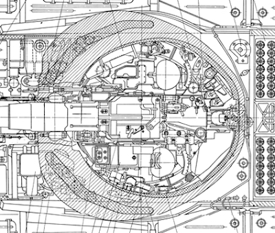
The difference between the diameter of the carousel top cover and the diameter of hole in the turret roof, very close to the bearing pitch diameter of 2,116mm, is very large, as the image below shows.

This is more than the T-64 and T-64A which has the crew seated in a turret cabin suspended from the turret ring, which separates the crew from the turret ring by a radius equivalent to the thickness of the ring of ammunition in the autoloader, reducing the diameter of the crew space to only 1,590mm or less. Maximizing the width of the lower part of the fighting compartment is considered less important than maximizing the width of the upper part because the legs of the crew occupy less space than their shoulders (average human shoulder width: 450mm, average hip width: 350mm), not to mention that some elbow room is needed for the crew to operate the equipment in their respective stations. Even so, the additional width provided by the design of the T-72 autoloader is still a noticeable benefit. One major reason is that the turret is low enough that the turret crew will have at least part of their torsos below the level of the turret ring, and the gunner has his elbows below the level of the turret ring practically at all times while carrying out his duties.
For instance, it can be seen in the images below (T-80B left, T-80U right) that, while the width of the crew stations is the same as the T-72 aside from the constrained diameter imposed by the cabin, and is quite generous, the space taken up by the cabin limits the size of the seats, particularly in the case of the T-80U where the cuts make the width and length constraints apparent.


The turret ring diameter of the T-72 is smaller than the turret ring diameter of the Leopard 2 (1,980mm), the Chieftain (2,159mm) and the M1 Abrams (2,159mm). Another factor behind the smaller internal volume of the turret of the T-72 - aside from the fact that it is built to accommodate only two crewmen instead of three - is the teardrop geometry which maximizes the frontal protection of the turret with minimal armour mass.
However, the actual available crew space inside the T-72 turret is increased thanks to the compactness of the 125mm D-81T gun. When measured at the widest point of its gun cradle and fixed recoil guard, the width of the gun is only 600mm. For comparison, the width of the Rh 120 smoothbore gun measured across the recoil guards is 660mm, according to data given by Dipl-Ing Rolf Hilmes in a seminar. Additionally, a measurement of the M68 gun on display at the Museum of Polish Military Technology showed that the width across the recoil guards is 672mm. The width disparity in favour of the T-72 translates to increased room for the crew in the turret. Coupled with the wide 1,934mm internal turret ring diameter of the T-72, it turns out that the maximum width of the gunner's and commander's stations is 667mm.
For the Leopard 2, the turret ring diameter is not indicative of the internal turret width because the side armour over the crew compartment (310mm in thickness) overhangs the turret ring by a significant amount and takes up additional internal space. After subtracting the overhang, the internal width of the turret coincidentally turns out to be 1,934mm - the exact same as the T-72. After subtracting the width of the Rh 120 gun cradle, the maximum width of the two halves of the turret occupied by the crew members is around 637mm.
This difference is illustrated in the two drawings below. Note that in the T-72 cross section, the proportions of the various internal components and the turret walls are not accurate. The image is used only to demonstrate the points of measurement.


Besides the space allocated to the crew, there are other factors affect the comfort of the crew such as thermal regulation and ventilation. For collective ventilation, the T-72 features an FVU (filter-ventilator unit) which serves as a regular blower for general ventilation of the crew compartment and a filtration unit with an overpressure generator, driven by a supercharger. As a filtration unit, the FVU performs both cyclonic separation of coarse particles and fine filtration via HEPA elements. The purified air is then accelerated by a supercharger to ensure a rapid flow of air, sufficient to generate an internal overpressure. As it is a filter element and not a mechanical separator like the supercharger fan, the FVU filter needs to be checked after every 6,600-7,000 km of use.
This difference is illustrated in the two drawings below. Note that in the T-72 cross section, the proportions of the various internal components and the turret walls are not accurate. The image is used only to demonstrate the points of measurement.


It is important to keep in mind that the actual crew space width is slightly less, because there are additional safety guards in both tanks. Still, it can be seen that the T-72 is not inferior to more modern counterpart in critical dimensions for crew ergonomics. According to the REO-SV-80 guidelines (Guidelines for the ergonomic provisions of the creation of military equipment for the ground forces), the crew station width should be 580mm wide for a tank gunner and 600mm wide for a tank commander. The T-72 conforms to these guidelines.
The AZ autoloader used in the T-72 permitted free movement between the fighting compartment and the driver's compartment as there is a gap of approximately 500mm between the carousel and the hull ceiling, creating a crawlspace of sufficient size for an average man. The crawlspace is only inaccessible if the turret is turned to face the direct rear, thus positioning the autoloader elevator mechanism over the gap. It is also blocked if the commander's seat adjustment mechanism is positioned directly over the gap. Crawling to and from the driver position is possible when the turret is facing forward, but very challenging because of the multitude of gun stabilizer components hanging below the 125mm gun, constricting the crawlspace size. When the tank has its turret turned to the travel position or has its turret oriented forwards or to the sides, which highly likely in combat, there is sufficient space that a wounded driver can be evacuated through the turret by either of the two other crew members, or conversely (and more importantly), the crew members in the fighting compartment can crawl into the hull to access the escape hatch in the belly.
Moreover, if the tank is driven into a deep water-filled ditch, the crawlspace gives the driver an avenue of escape as the driver's compartment is filled with water or at least provides enough room for the driver to keep his head above water.

VENTILATION
Besides the space allocated to the crew, there are other factors affect the comfort of the crew such as thermal regulation and ventilation. For collective ventilation, the T-72 features an FVU (filter-ventilator unit) which serves as a regular blower for general ventilation of the crew compartment and a filtration unit with an overpressure generator, driven by a supercharger. As a filtration unit, the FVU performs both cyclonic separation of coarse particles and fine filtration via HEPA elements. The purified air is then accelerated by a supercharger to ensure a rapid flow of air, sufficient to generate an internal overpressure. As it is a filter element and not a mechanical separator like the supercharger fan, the FVU filter needs to be checked after every 6,600-7,000 km of use.

Additionally, the supercharger of the ventilation unit can be used while bypassing the filtration system in an auxiliary mode by turning it on manually. This can be done to enhance airflow in the crew compartment in hot weather. The supercharger is also connected to the firing circuit of the main gun and coaxial machine gun. When either the main gun or the machine gun is fired, the supercharger turns on automatically to increase air circulation in the crew compartment, helping to evacuate the fumes from the weapons so that an excessive concentration of fumes does not accumulate during sustained fire. When operating the coaxial machine gun or main gun manually due to a failure in the electrical firing circuits, the technical manual for the T-72 recommends turning on the supercharger manually before firing.
In recent tank models with a modernized autoloader, including the T-90A and T-72B3, the spent casing ejection port also briefly opens after a shot is fired from the main gun. Combined with the automatic activation of the supercharger, a reduction in the concentration of propellant fumes in the tank is achieved.
For local ventilation, each crew member in the tank is provided with a DV-3 personal fan, a simple 5.2W fan running on the tank's 27V electrical system.
When the tank is driven in regions with a hot climate, ventilation for the crew is supplemented by opening the OPVT intake hole in the engine compartment bulkhead, allowing the engine to draw air from the crew compartment. The effect of doing so is that the ventilator is combined with the powerful draw of the radiator cooling fan to create a strong draft inside the crew compartment. At the same time, this can improve the purity of the air for the engine in dusty environments. When using this method of ventilation, the supercharger should be turned on, or at least one hatch should be ajar, or the snorkel mount hole in the gunner's hatch should be opened. The diagram below shows the OPVT intake hole and the pulley mechanism used to open it from the driver's compartment. When opened, air is drawn through the crew compartment into the engine compartment, past the rear end of the engine near its exhaust ducts, and out through the cooling fan outlet. Opening this intake hole does not come without its costs though, as doing so will slightly increase the pressure in the engine compartment, compromising the negative pressure inside the engine compartment which draws air through the radiators. In situations where cooling efficiency is critical, such as in extremely hot weather conditions, it is imperative that no loss of efficiency is introduced, to prevent the engine from overheating. In such circumstances, the crew is obliged to acquiesce to the needs of the tank rather than their own.

Besides a fairly good ventilation system, the T-72 also featured a heater, adapted from the heater in the T-64. The heater is a dual-purpose device designed to pre-heat the engine before starting it in ambient temperature conditions of 5°C or below when using diesel and kerosene fuel, or when operating at 20°C and below when using gasoline. It was also designed to provide heat to the fighting compartment of the tank via a built-in radiator when it is turned on during engine preheating. The heater is installed at the rear starboard corner of the fighting compartment, beneath the fighting compartment ventilator and next to the rear hull conformal fuel tank. The fuel consumption rate is no more than 9 liters per hour, and it can run continuously. The only limit on the duration of operation is the fuel supply.
The device generates heat by producing a jet of flame in a special boiler using any of the three fuel types specified for the T-72 - diesel, gasoline or kerosene. The boiler heats up the coolant (water), which is circulated around the engine and oil tanks in a closed loop by a boiler pump powered by an electric motor with a manual backup. The same electric motor also powers the air intake fan which supplies air to the boiler and powers the fuel pump which supplies fuel to the boiler. Exhaust gasses from the combustion chamber in the boiler are ejected out of the tank through an exhaust outlet on the side of the hull.
The device generates heat by producing a jet of flame in a special boiler using any of the three fuel types specified for the T-72 - diesel, gasoline or kerosene. The boiler heats up the coolant (water), which is circulated around the engine and oil tanks in a closed loop by a boiler pump powered by an electric motor with a manual backup. The same electric motor also powers the air intake fan which supplies air to the boiler and powers the fuel pump which supplies fuel to the boiler. Exhaust gasses from the combustion chamber in the boiler are ejected out of the tank through an exhaust outlet on the side of the hull.
Heating for the fighting compartment of the tank is providing by a small tube radiator marked (9) in the drawing below which is heated with hot water from the boiler or from the engine. A fan, marked (6) in the photo below, blows air through the radiator to ensure that heated air circulates around the enclosed space of the tank fighting compartment more quickly. The heater fan is quite powerful, being driven by an MV-42 motor operating at a power of 175 W and turning at 3,500 RPM. Fans with the same motor are used in the ventilation exhaust fans in the T-10 heavy tank series. When using the heater while preheating the engine, the boiler pump of the heater is used to circulate hot water through the small radiator and the engine simultaneously. When using the heater with the engine running, the running engine heats up the circulating water which is pumped through the mini radiator under pressure from the main coolant pump, and heat for the crew is generated without using either the boiler or the boiler pump. To better appreciate the usefulness of this feature, it should be noted that on some tanks, heating for the fighting compartment is only provided by opening a flap in the engine compartment bulkhead to allow engine heat to enter which is a simple and dependable heating method but may also allow various noxious fumes to pollute the crew compartment. Heaters that depend on a boiler or electric element also tend to have very low reliability. This solution of using the tank's coolant with a mini-radiator, was an ingenious solution to the issue of reliable heating, which can be credited entirely to the original T-64 design.
When running, the boiler effectively turns the preheater into a hot plate, which can be used to heat ration tins and water.


Since the heater is installed beneath the fighting compartment ventilator, the flow of air from the ventilator blower fan helps to circulate the hot air inside the tank. The heater unit is shown in the photo on the left below (photo originally shared on btvt.narod). The heater exhaust outlet is situated between the fourth and fifth roadwheels on the starboard side of the hull, as shown in the photo on the right below (photo credit to Thomas Voigt).


A serious design flaw of the heater was that dirt or snow could enter the exhaust outlet and cause a blockage despite the outgoing flow of exhaust gasses, and frequent cleaning is required as soot accumulates easily in the combustion chamber of the boiler. This was a chronic source of heater breakdowns, giving it the reputation of being high-maintenance and unreliable. On the other hand, the likelihood exists that much of the soot accumulation issue stems from the use of the heater with worn and discharged batteries, since the T-72 technical manual states that it is prohibited to use the heater when the master power is less than 22 V as this leads to rapid carbon formation on the walls of the heater.

A major advantage of the heater design is that the boiler does not need to be running to provide heat for the crew, as heat is supplied by the engine with the added bonus of somewhat contributing to the cooling of the engine. However, the system does not feature a temperature regulator as the heating element is not electric and the radiator fan motor has no speed control, so the fighting compartment heating system can only be either on or off using the toggle switch on the driver's instrument panel. The crew compartment is heated up at an accelerated rate while preheating the engine due to the large heat output of the boiler, and once the engine is started, heat for the crew compartment is sourced from the engine. The main disadvantage of the system is that heated air is not dispensed from vents at the individual crew stations like in a T-80.
Furthermore, the T-72 had a thick internal anti-radiation lining on the surfaces of the turret and hull. On the frontal cheeks of the turret where the armour was thickest, the lining was only 10-20mm thick as the armour itself provided good shielding from penetrating radiation such as gamma rays and neutrons, but on other parts of the tank including the sides, rear, and ceiling of the turret, the sides of the hull, and on the autoloader carousel cover, the anti-radiation lining was 45-50mm thick to compensate for the low thickness of armour. This lining was known as "Podboi". Beginning in 1983, an external anti-neutron cladding with a thickness of 50mm was added on the turret and hull surrounding the inhabited parts of the tank as a response to an announcement by U.S president Ronald Reagan in 1981 that the production of neutron bombs would be restarted. This cladding was known as "Nadboi". Both the internal lining and external cladding were made from a laminate of hydrogen-rich polyethylene (UHMWPE) and polyisobutylene sheets impregnated with lead.
Besides offering excellent protection from harmful radiation and blast waves as detailed in Part 2 of this T-72 article, the thick anti-radiation lining inside and outside the tank provides thermal insulation for the crew and internal equipment in hot and cold weather. In cold weather, the temperature of the steel shell of a tank eventually equalizes with the outside temperature so that the crew would essentially be sitting in an ice box, and when the temperature drops below 0 degrees Celsius, the steel surfaces of a tank become too cold to be touched safely with bare skin. The same is true in hot weather as the interior of a tank heated by direct sunlight will become hotter than the ambient air temperature, given enough time. The laminated polymer material (polyethylene and polyisobutylene) of the anti-radiation lining acts as an insulator and a physical barrier between the steel shell of the tank and the crew, thus ensuring that the crew cannot accidentally burn or freeze themselves on the bare steel surface while also helping to regulate the internal temperature of the tank; in winter, the lining helps retain heat inside the crew compartment, and in summer, the lining helps prevent the heated steel shell from raising the internal temperature. The additional "Nadboi" cladding found on newer tanks adds another layer of insulation that is particularly useful in summer as the turret roof is the most exposed to sunlight.
The only foreign tanks with a lining comparable to "Nadboi" in insulation characteristics were the Chieftain and Challenger 1, both of which had a thin foam-backed plastic liner on the majority of the turret and hull surfaces in the crew compartment. This lining, which is around an inch thick, is reported to provide insulation against solar heat, cold and noise in a 1966 edition of the Chieftain user manual.
It may seem trivial, but temperature regulation inside a tank is important. Having an internal heater and a layer of insulation on the walls of the tank is a basic necessity for cold winters - something which the T-72 has and some tanks do not. For instance, the personnel heater in the M60A1 and M60A3 was astonishingly unreliable. According to a 1983 TACOM report titled "M60 Tank Personnel Heater Comparison Test", the original Model "B" heater in the M60A1 was atrociously unreliable and frequently caused the automatic fire extinguisher system in the tank to discharge accidentally. The problems were recognized and a newer Model "C" heater was installed in M60 tanks since May 1980, but these were still extremely unreliable and the issue of frequent accidental fire extinguisher discharges was still not solved. The Model "C" heater had a mean time before failure (MTBF) of just 70 hours and the mean starts before failure (MSBF) was only 25 starts. Without reliable heating, the efficiency of the crew in wintertime or even during rainy weather would have been reduced.
Even worse, some tanks like the Chieftain had a lining but did not have a heater at all, forcing the crew to depend entirely on multiple layers of clothing and thick mittens. This omission was only remedied in the final four years of the Chieftain's service life with the Mk. 10 model, but even then, the system was beset by serious issues; according to Rob Griffin, turning on all three of the new heaters would shut down the tank's electrical system. With that in mind, the famous boiling vessel or "BV" commonly found in British armoured vehicles seems much less like a morale-boosting appliance mandated by the Ministry of Defence for the benefit of weary tankers, and more of a basic necessity to ensure a modicum of comfort. Only the Leopard 1 provided the crew with both a personnel heater and a hot plate from the very first production models, making it arguably one of the most habitable tank of its peers even though, much like the T-72, it was not the most spacious.
In a T-72, each crew member was provided with a two-liter aluminium bottle which was stowed in a special holder near their respective stations. Officially, the bottle is meant for drinking water, but it can be filled with anything that the individual crew member desires. There is no provision for heating rations other than to place the ration tin next to the boiler of the heater or place it in the engine compartment via a flap in the bulkhead. With that, practically all aspects of the ergonomic design of the T-72 have been discussed, and a detailed examination of the primary characteristics of the tank can begin.
In a T-72, each crew member was provided with a two-liter aluminium bottle which was stowed in a special holder near their respective stations. Officially, the bottle is meant for drinking water, but it can be filled with anything that the individual crew member desires. There is no provision for heating rations other than to place the ration tin next to the boiler of the heater or place it in the engine compartment via a flap in the bulkhead. With that, practically all aspects of the ergonomic design of the T-72 have been discussed, and a detailed examination of the primary characteristics of the tank can begin.
For internal lighting, a T-72 has three PMV-71 dome lights and eight KLST-64 cabin lights. Both types of lights have the same TN-28-10 incandescent light bulb, which operate at up to 28 V and consume 10 W. The dome lights serve as the main and emergency lights, as they are not connected to the power supply network of the tank but are instead wired in a separate circuit with the tank's batteries. One dome light is installed on the ceiling of the driver's station and two are on the ceiling of the commander's station for global illumination, and for the convenience of the commander when reloading the coaxial machine gun. The eight KLST-64 cabin lights serve as additional local lighting at all crew stations, mainly for illuminating specific control panels. They can be switched on or off and have sliding lids to adjust the light levels.
Additionally, the tank has three ShR-51 power sockets, mainly to supply power to portable lamps but also for night vision devices such as the PNV-57. The power socket resembles the cigarette lighter in cars. There is a power socket on the ceiling of the driver's compartment and one in the turret behind the gunner's seat. The third socket is outside the tank, next to the rear left convoy marker light. Unlike the T-10 heavy tank series, there are no cabin lights inside the engine compartment for servicing at night, so a crew member or mechanic must use a portable lamp instead, and the external power socket is placed there for that purpose. Additionally, the external power socket is used to plug in the MZA-3 fuel filler unit, with which the tank crew can refuel the tank independently of a fuel filler truck or refill the engine oil reservoir. The MZA-3 unit is a powerful, compact device that can pump out diesel at 60 liters per minute. The MZA-3 is also used to clean the air filter elements for the engine air intake system, which is cleaned by washing it with a powerful flow of diesel.
As is usual for tanks, the electrical network is a decentralized system, where the power source is connected to multiple independent electrical hubs, which all of the electrical devices are connected to. Only the dome lights and the electric motor of the bilge pump are not connected to the power distribution system, but are instead wired directly to the tank's batteries. Power transmission is done by single-wire connections. The use of a single-wire scheme for power transmission served to reduce the weight of the wiring harnesses in the tank, as substantial weight savings could be gained by omitting a return wire from each connection. The body of the tank itself serves as the ground.
In total, the electrical and pneumatic equipment built into the T-72 provided it with a level of self-sustainability that could theoretically allow it to indefinitely maintain a combat-ready status in field conditions without the involvement of additional maintenance support, as long as the tank remains supplied with consumables, including fuel, oil, water, food and ammunition.
COMMANDER'S STATION


The commander's cupola follows the same layout that was first implemented for the cupola of the T-54 obr. 1949, but with some significant differences. The T-72 cupola has a more thickly armoured hatch, and the hatch has a clam shell shape rather than a simple semicircular shape. It is also slightly taller and has a more pronounced dome shape due to the large thickness of the anti-radiation lining on the hatch. In terms of width, the T-72 cupola is very similar to the older cupolas of the T-54, T-55 and T-62. Structurally, it differs in the shape of the hatch and fixed roof, but it also differs in that it lacks the ventilation hole which is used during deep fording and for enhanced ventilation. This role was taken over by the snorkel hole on the gunner's hatch. The race ring of the T-72 cupola extends below the turret roof, whereas the one in the T-54 cupola does not. This is because the T-72 cupola has an additional toothed ring that engages with the counter-rotating mechanism. This feature will explored further later on.


The cupola housing is secured to the cast steel turret roof by a ring of bolts around its circumference, but unlike the T-54 cupola, the bolts are sheltered against gunfire and the weather. The T-72 cupola is also more complex as its race ring is not directly connected to the fixed base bolted to the fixed cupola housing but to an intermediate metal band, and that connects to the cupola housing via a larger race ring. The intermediate metal band is between the inner cupola (which carries the optics and hatch) and the fixed base. It serves as the machine gun ring mount. By releasing a locking mechanism, the intermediate band can be freed from the fixed base, thus allowing it and the machine gun installed on it to be rotated degrees independently of the rest of the cupola, as you can see in the photo below (photo from Russian Ministry of Defence).

This is also apparent in the photo below showing that the cupola is completely independent from the machine gun mount. Both the cupola and the anti-aircraft machine gun can be rotated without being interrupted by each other.

The independence of the machine gun mount from the cupola is demonstrated in this video, and in this video. This video from TV Zvezda shows a fully assembled turret with the machine gun cradle on its mount, traversed to a forward position. By separating the machine gun mount from the cupola, the commander does not have to bear the weight of the heavy NSVT machine gun (25 kilograms), the machine gun ammunition and the machine gun mount itself when he rotates the cupola which is especially important because the machine gun is mounted eccentrically to the axis of rotation of the cupola, so the center of gravity would be shifted and the cupola would become imbalanced. Overall, this design feature reduces the amount of physical effort required to rotate the cupola, especially if the tank is on a slope. This issue was solved in the T-64A obr. 1975 by using an electric cupola traverse system (part of the remotely controlled anti-aircraft machine gun complex) so that the commander is not required to rotate it manually, but the T-80 and T-80B had its machine gun mounted directly on the cupola and the T-80U skirted the problem by having its anti-aircraft machine gun installed on fixed posts welded to the turret roof at various points. This aspect of the commander's cupola is further discussed in the section on the anti-aircraft machine gun later on.
If the anti-aircraft NSVT machine gun ring is locked facing the rear, the cupola can only be rotated in a 320-degree arc, with a 40-degree dead zone directly behind it. This is due to the base of the machine gun pintle blocking the cupola along a sector with a width of 40 degrees. The cupola is stopped against the base of the pintle by a protruding lug, highlighted in red in the drawings below. As the drawing shows, this lug overhangs the machine gun race ring so that it will be blocked against either the base of the pintle if the cupola is turned to the right, or blocked against the machine gun race ring locking device if the cupola is turned to the left. This traverse limit was presumably put in place so that the spotlight would not collide against the machine gun. If the machine gun ring is unlocked from the turret and coupled to the cupola, the cupola can make a full rotation.


The commander's seat has a robust design with a large square cushion and a large square backrest attached to the seat frame. It can be adjusted in height by releasing a locking pin via a squeeze handle, allowing the seat to be pushed up by a spring and locked in a raised position or pushed down by the commander's body weight and locked in a lowered position. The backrest can be folded inward to allow the commander to access any ammunition stowed behind the seat or to allow the driver to enter the turret if the turret is oriented to the rear of the tank. The seat can be removed by rotating it upward by 45 degrees and pulling it straight out in the same direction. It can also be folded fully in the vertical position. With the seat raised, the commander is seated normally with his feet resting flat on the autoloader carousel cover and he is in the best position to look out through the vision devices in his cupola. With the seat lowered, the commander can sit with his legs outstretched. During combat, the commander does not sit with his legs outstretched because there is less legroom on the autoloader carousel cover than the gunner has on his side of the turret, and because the ammunition box and spent link collector for the coaxial machine gun hang well below the turret ring level, so there is not much clearance if the gun is elevated.


A removable recoil guard is attached to the commander's seat to shield him from the recoil path of the main gun when it fires. The top part of the recoil guard can be folded away to permit freer access to the gun breech or to allow the commander to crawl to the gunner's station and vice versa, and the entire recoil guard can be folded or removed to grant access to certain parts of the autoloader, mainly to replenish it with fresh ammunition. It is also removed if it is necessary to reload the main gun manually. To maximize the space available to access the autoloader carousel, the seat would be folded up, the backrest will then be folded inward over the seat and the recoil guard would be removed. This removes all obstructions between the commander and the carousel.
The width of the commander's station, as measured at the position of the commander's torso, is 635mm (25 inches). The height of the station is 890-914mm (35-36 inches) when measured from the seat cushion to the ceiling of the cupola, when adjusted by a 5'10" man to view from the vision devices. The seat can be lowered to accommodate a taller man.


Since the mid-2010's, T-72 tank crews are issued with 6B15 "Cowboy" suits, and the added bulk of the fragmentation vest can be a hindrance to the commander when moving through the narrow hatch opening. However, it is important to keep in mind the difference between a 95th percentile U.S male and a typical Soviet or Russian tanker.
The hatch is spring-loaded with a plate torsion spring built into the hinge to assist the commander in opening the hatch, as it is quite heavy due to its thick armour and the thick anti-radiation lining on its underside. It weighs 125 kg. A simple rotating handle locks the hatch when closed, preventing it from bouncing up and down when the tank is in motion, and a smaller handle at the bottom of the hatch serves to lock the hatch in place when it is opened, which is useful when the commander wishes to view the battlefield from outside the hatch, or when he needs to use the complementary cupola-mounted machine gun.


Because it opens forward, the thick hatch gives the commander full-body protection from machine gun fire whenever he wants to pop out to observe his environment. To look over the hatch, the commander raises his seat to the tallest setting and stands on the seat. This allows him to stand with just his eyes peeking above the edge of the hatch, depending on the height setting of the seat. The image shown below, taken from a DDR training film provided by the Bundesarchiv, shows the commander and gunner of a T-72M standing behind their respective hatches.

The commander may even stand on the recoil guard and the height adjustment mechanism of his seat to gain a taller vantage point without completely exiting the vehicle. This would often be done when signalling with flags.


It is possible for the commander to sit on the backrest of his seat, allowing him to expose himself from chest level above the rim of the cupola. His view forward is blocked by the hatch unless it the cupola is swiveled to one side. Alternatively, he can fold up the seat to stand on the autoloader carousel (if the machine gun ammunition box stowed under it is removed) and have the cupola locked facing the rear. Due to the limited vertical space inside the tank, the commander exposes himself up to chest level this way, or less if he ducks down.
During long marches, the commander may opt to sit on the rim of his hatch. In this position, the commander still has front body protection from the hatch. It is important that the commander can sit outside the tank during long marches as he would otherwise need to stand on his seat for hours at a time with no movement. If a commander stands still in this way on maneuvers that last all day, he becomes extremely fatigued and his feet can become swollen.


Beginning in the mid-70's, the commander's cupola may also have dust shield installed forward of the hatch. This shield, which is part of the same set as the weather hood for the driver, is installed before long marches in convoys. It would be dismantled before combat.

The lower part is a simple hanging fabric sheet, which covers the commander's hatch when it is opened. The upper part is just a face shield for the commander for if he were to sit outside on the turret. It protects the commander from having dust and bugs blown directly into his face when travelling in a typical single-column marching formation.


The shield made of thin sheet steel with an equally thin polycarbonate or perspex window and is thus not bulletproof, splinter-proof or fragmentation-proof although the commander's hatch certainly is. Therefore, the protection afforded to the commander does not change.

Like in the other two crew stations, the commander is ventilated by a single adjustable DV-3 fan, a simple 5.2W fan running on the tank's 27V electrical system. Although it may seem silly in its simplicity, it is an important feature for keeping the crew comfortable or at least functional in the summer heat. Foreign tanks such as the Leopard 1, M60A1 and Chieftain, as well as their replacements, all had a ducted ventilation system with air outlets at every crew station in the turret. The DV-3 is shown in the photo below.

The DV-3 is closely related to the DV-302T, which is a very similar fan used in aircraft like the Mi-8 helicopter, Il-76 and many more. In other words, the DV-3 was essentially an off-the-shelf product at the time the T-72 began mass production.
Because the commander has his own hatch, he may opt to simply stick himself out of the hatch and ride on the turret roof if he feels uncomfortable inside the tank. For additional ventilation in the crew compartment, the air source for the engine can be switched from the external intake to the crew compartment intake. The crew compartment intake draws air from the crew compartment, which greatly increases the airflow inside the tank if the hatches are open. Normally, the crew compartment air intake is designed to provide an alternate air supply for the engine during fording and snorkeling maneuvers where the depth of the water obstacle is more than 1.8 meters. When fording streams, the hatches on the turret roof should be left open if the situation permits, but if combat is imminent, the crew must have the hatches closed and only the snorkel tube installation port in the gunner's hatch is opened. In both cases, a tremendous volume of air flows into the fighting compartment through the openings to aspirate the engine, thus cooling down the crew. This would undoubtedly be very welcomed in hot weather.
The commander's main means of surveying the battlefield is a forward-facing TKN-3M binocular periscope, augmented by two rectangular TNPO-160 periscopes on either side and two TNPA-65A periscopes embedded in his hatch. The TKN-3 periscope is aimed directly forward and is aligned with the centerline axis of the cupola. As there is no unity vision capability from the TKN-3, the commander is inconvenienced when he wants to have a wide, unmagnified forward view as he has to turn the cupola and use his other periscopes. The two TNPO-160 periscopes flanking the TKN-3 are oriented 45 degrees from the centerline of the cupola. The drawing below shows the TNPO-160 in a generic tank mount, the sheet metal rain hood above the periscope head, and the rubber seal around the periscope slot that prevents the ingress of water into the vehicle.

With just these two periscopes, the commander has vision in a 176-degree frontal arc with a blind spot of 22 degrees to the direct front which is filled by the TKN-3. Because the cupola can rotate, the five periscopes in the cupola provide the commander with an all-round view when he is in a closed-hatch condition. There is no periscope that allows the commander to see directly behind the turret. For that, he must spin the cupola to one side and look out of either one of his TNPO-160 or TNPA-65A periscopes, although the anti-aircraft machine gun would usually be in the way as it is stowed directly behind the cupola in the "travel" position when not in use. Due to the conformal slant of the gunner's hatch on the left side of the turret, the commander's view to the left of the turret is largely unimpeded. Even the gunner's night vision sight does not completely block the commander's view as the height of the sight housing does not exceed the maximum height of the turret roof.
However, the commander's view to the left of the turret in the 10 o'clock sector was obstructed when Kontakt-1 reactive armour blocks were installed on the roof of the turret beginning with the T-72AV modification in 1985. This problem persisted when Kontakt-5 blocks replaced the Kontakt-1 blocks in the T-72B obr. 1989 model and continues to plague the T-90A. For these later models, the burden of monitoring these sectors falls upon the gunner. The photo on the left below shows the cupola of a T-72B3, and the photo on the right below shows the view from the left-facing TNPO-160 in the cupola of a T-72B3 looking at the Kontakt-5 blocks on the turret roof.


The TKN-3M periscope window is slightly more elevated than the other periscopes in the cupola, giving it more clearance over the clutter on the turret roof. As such, its field of view was largely unaffected when reactive armour blocks were added to the turret roof in later T-72 models. The video clip below shows archival footage from a Czechoslovakian Army training film showing the cupola of a T-72M being used to scan the forward 180-degree sector of the tank. Original video from the VHU channel. Note that the anti-aircraft machine gun is locked in place behind the cupola.

For general vision, the commander is provided with four periscopes to supplement the TKN-3. In total, the field of view of the commander from the cupola (without head movement) is 288 degrees, with a 72-degree dead zone to the rear. Due to the use of periscopes instead of vision blocks (slits with glass blocks) and the thick turret armour around the base of the cupola, the commander is completely protected from concentrated machine gun fire directed at the periscopes. There is absolutely no chance that for his eyes to be injured by broken glass due to the nature of solid glass prism periscopes and because the periscope eyepiece is protected by an additional layer of ballistic glass, as shown in the photo on the left below.


The volume of fire expected to hit the periscopes directly changes drastically depending on the distance between enemy combatants. Aimed machine gun fire is very unlikely to knock out a periscope unless it is from very close range, but as a tank closes in to overrun an enemy position, it becomes quite easy to do so. During WWII, infantrymen were taught to fire at the observation devices of tanks as a last resort and in many cases, these observation devices were merely slits or slits with glass inserts that gave minimal ballistic protection for the crew member using them. The effectiveness of such tactics was amplified if an anti-tank rifle like the PTRD was available.
This was one of the most persuasive incentives to use periscopes, but the improvement in user safety did not remove the incentive for enemy infantrymen to concentrate fire on the observation devices and these experiences have been validated time and time again, most recently during the current conflict in Syria where much of the fighting takes place in densely populated urban areas. The video still below, taken from this video, shows a Syrian T-72 with two of its periscopes destroyed.

The TNPO-160 has a total field of view of 78 degrees in the horizontal plane and 28 degrees in the vertical plane.
The TNPA-65A periscopes embedded in the hatch have a particularly noteworthy design among tank periscopes in that the periscope was specficially designed for tank hatches. Due to the position of the viewing window, the lower prism has an offset angle of 45 degrees, so that it is best used by the observer looking up at 45 degrees. Because it is not intended for the user to press his face against the viewing window when using the periscope, the TNPA-65A is not protected by additional ballistic glass, thus allowing it to retain a high light transmission coefficient of 0.6.


The total field of view from a TNPA-65A is 140 degrees in the horizontal plane and 35 degrees in the vertical plane. This is somewhat more than the TNPO-160, despite having the same width and a narrower viewing window. This is due to the periscopic effect which restricts the size of the image proportionately with the distance between the viewfinder window and the objective window. The periscopicity of the TNPA-65A is only 65mm, whereas the periscopicity of the TNPO-160 is 160mm. Due to their location in the hatch and their small size, it is ergonomically unfavourable to use them compared to the conventional TNPO-160 periscopes, as it is not feasible to press his eyes up against the viewing window because it is too close to the surface of the hatch. The ergonomic limitations of the TNPA-65A are, however, counterbalanced by their excellent field of view, and the high brightness of the image due to the high light transmission coefficient.
When seated with his eye level aligned to the TKN-3M eyepieces and the TNPO-160 periscope windows, the field of view through the TNPA-65A periscopes in the hatch can be estimated to be equivalent to the field of view through the TNPO-160 periscopes. When compared to the equivalent T-54/55 or T-62 commander's cupola, which had regular periscopes embedded in the hatch, the use of the TNPA-65A allowed the hatch to be free of large protrusions, making it more convenient when ingressing and egressing.
K-108 cerium-doped glass is used for all of the periscopes. This special grade of glass ameliorates the browning and darkening caused by gamma radiation exposure, and is able to regain its clarity after several hours of exposure to sunlight. With ordinary glass periscopes, gamma radiation causes permanent darkening. Several of the viewing devices in the tank are electrically heated using the RTS-27-4A system to prevent fogging in cold weather. RTS stands for "Регулятор Tемпературы Стекла", which means "Glass Temperature Regulator".

The commander's cupola of the T-64 lacked an anti-aircraft machine gun and was furnished with only one TKN-3M periscope and two TNPO-160 periscopes. The field of view (without head movement) was 144 degrees. This cupola was carried over to the T-64A. Given that a successful template for a periscope layout in a cupola of this design was already established since the T-54 obr. 1949, it is a mystery why the T-64 cupola had such constricted visibility. Needless to say, the T-72 was vastly superior in this particular aspect. In 1975, a new and much more technically advanced cupola with a ZU-64A remotely controlled anti-aircraft machine gun system was implemented on the T-64A obr. 1975. Two TNPA-65 periscopes were finally added to the hatch of the new cupola, but to accommodate the PZU-5 sight for the ZU-64A system, the TNPO-160 periscope on the left of the TKN-3 had to be removed. As a result, the commander's visibility was still not on par with his T-72 contemporary. In fact, the higher statistical weight of forward-facing periscopes compared to side or rear-view periscopes makes the new cupola a downgrade over the older version, despite the increase in the number of periscopes. These nuances are important when evaluating the validity of various cupola designs.


Compared to a typical Western tank cupola, the number of fixed periscopes in the T-72 model is clearly less, but the number alone is not necessarily indicative of actual utility. For example, the Leopard 1 provided its commander with eight periscopes arranged around his circular cupola, but only five are aimed in the forward 180-degree sector and two of them are partly obstructed by the loader's cupola, loader's machine gun skate mount and loader's hatch opening mechanism on the left side of the turret. It is also important to note that the commander's cupola on the Leopard 1 does not rotate and the forward-facing periscope has a very high periscopicity so that the field of view in inherently narrower. In other words, the number of vision devices providing a view towards the forward half of the turret is not more than in the T-72 commander's cupola and there are other secondary factors that affect the commander's visibility. A T-72 commander only loses out in convenience when directing the driver to reverse the tank as he must rotate his cupola in order to see behind the turret or have the turret aimed to the rear.
To further expand our perspective, it should be noted that the commander of an M60A1 is furnished with eight M41 prismatic vision blocks arranged around his oblong M19 cupola, with one aimed forward to cover the 11 o'clock sector, two of them aimed in the forward arc to cover the 10 o'clock and 2 o'clock sectors, two of them aimed to the sides, and three of them aimed in a 7 o'clock to 5 o'clock arc. There is one wide-vision periscope installed just behind and above the M85 machine gun in the cupola and aimed directly forward. Adding on the fact that the M19 cupola can rotate, and it is clear that an M60A1 commander has much better visibility than a T-72 commander under practically all circumstances. However, none of the M41 vision blocks are heated, so fogging will tend to seriously degrade visibility in chilly weather. Also, the objectively poorer rearward visibility from the T-72 cupola compared to Western tanks does not necessarily translate into objectively poorer combat performance as the value of observation devices depends on the context in which they would be used. It is a perfectly valid observation that when the tank needs to reverse, it is often in a non-combat situation where it is safe for the commander to be outside his hatch. In combat, it may be necessary to reverse in order to change positions or to reverse into turret defilade after firing a shot. In both cases - and in general - the driver would have approached the firing position from behind in the first place so he already knows that the area behind the tank is clear of obstructions and that he can freely reverse without fear of running into obstacles. If it is truly necessary for the commander to direct the driver when reversing the tank, the commander can rotate the cupola and use one of his periscopes for the task or open his hatch and peer out.
Furthermore, the fundamental purpose of the fixed periscopes has to be understood in order to assign them with their proper value. In combat, such periscopes are generally only useful if the enemy is very close to the tank (500 meters or less). Otherwise, they are only good for viewing the surrounding environment in order for the commander to gain a sense of spatial control over the tank, and this is done by finding landmarks. When the tank is moving speedily across rough terrain, observation through fixed unmagnified periscopes becomes ineffective due to the oscillation of the tank and the restricted field of view. The commander only sees an oscillating flicker between the ground and the sky, with no possibility of reliably discerning camouflaged enemy forces let alone identifying them.
For a modern tank created and fielded during the mid to late Cold War era, it is only practical to see and identify targets using a magnified optic and some form of stabilization is mandatory to allow it to be used effectively in a moving tank, as the narrower field of view through a magnified optic will exacerbate the negative effects of the oscillation of the tank. The TKN-3 periscope for the commander of a T-72 fulfills this purpose as it has a reasonably high magnification with a reasonable field of view, and it has handles to allow the commander to hold it steady.
The characteristics of a tank commander's observation practices when buttoned-up in a fixed cupola with eight periscopes and one fixed forward-facing sight in the turret were examined in the 1974 study "Некоторые Статистические Характеристики Процесса Наблюдения Командира Танка" (Some Statistical Characteristics of a Tank Commander's Observation Processes) by G.G Golub et al. Three special cupolas were constructed to replace the original commander's cupola of a T-64 that was used as the experimental platform. The frequency and duration of usage of each of the viewing devices was recorded using a small forward-facing lamp on the commander's headset which would illuminate an array of photodiodes (light sensors) placed on top of each viewing device when the commander looks through the viewfinder. The first cupola design was a fixed type with eight fixed and equally spaced unmagnified periscopes arranged radially around the circumference of the cupola and one forward-facing TPD optic (modified periscopic sight with optical rangefinder removed). The second cupola design was the same as the first design but it had a stabilized electric drive for cupola rotation. The third cupola design was a manually-rotating type analogous to the T-72 cupola, having a total viewing arc of 206 degrees (± 103 degrees from the centerline axis of the cupola).

These cupolas were tested in various simulated combat conditions. The simulations were carried out in field conditions with moderately hilly terrain partly covered with bushes and trees. The targets included four tanks showing their frontal projection, three tanks in hull-down positions, two armoured personnel carriers, three ATGM teams, five recoilless rifles, and five anti-tank guns. All of these were arranged in such a way as to ensure that they would be uniformly concealed from the tank commanders as the tanks traveled down the pre-planned routes from a full 360-degree arc and at distances of 0.5 to 1.5 kilometers. The positions of the targets were shuffled throughout the experiments.
It was found that in general, 30% of all battlefield observations were carried out using the forward-facing unmagnified periscope and at most, 5% of observations were done using the magnified 8x optic with a stabilized field of view. However, it was also found that in tactical situations such as carrying out a breakthrough mission, the frequency of the use of a magnified optic to search for targets increases up to 50%. Overall, more than 70% of observations were made using only three periscopes at the front of the cupola covering a 100-degree frontal sector and over 95% of observations were made in a 200-degree frontal sector. Most interestingly, the experiments revealed that the highest recorded frequency of usage of the rear-view periscope was only 0.8%. It was also noted that the periscopes installed at more than 110 degrees off the centerline axis of the cupola (8 o'clock) were difficult to use due to neck strain when the tank was in motion. This was most likely why the commander's cupola of the T-80 used a rear-view prism embedded in the roof of the commander's hatch instead of a conventional periscope placed behind the commander's head.
Based on these results, it can be seen that in a fixed cupola with all-round visibility, five unmagnified periscopes covering the front 180-degree sector provide 95.3% of the total visibility needs of the commander under various combat conditions. The rear-facing periscopes are rarely used. A rotating cupola that provides vision in a 206-degree arc will fulfill 98.1% of the commander's visibility needs under the same combat conditions. In other words, the practicality of the T-72 cupola design can be considered to be experimentally validated. Even a T-64 cupola with just one TKN-3 and two TNPO-160 periscopes can theoretically fulfill 70% of the visibility needs of its commander, but on the other hand, the improved visibility from the two additional TNPA-65A periscopes in the T-64A obr. 1975 or T-64B cupola is offset by the loss of one TNPO-160 periscope.
Of course, the configuration of observation devices in the T-72 commander's cupola is certainly not perfect. A panoramic sight is ergonomically superior as the user's head does not need to move when the sight head rotates. The Leopard 1 is exemplary in this regard as it provided its commander with the excellent TRP-2A panoramic sight featuring a variable magnification of 4x to 20x, and beginning with the Leopard 1A4 in 1974, the commander was provided with the advanced PERI-R12 stabilized panoramic sight with a variable magnification of 2x or 8x. Panoramic sights were developed in the USSR during the 1930's and the PT-1 sight was the first to enter service, being installed on the T-26. Later, the PT-K panoramic sights were used on various modifications of the KV-1 and T-34, and indeed, Soviet engineers in the prewar era saw much greater value in panoramic observation devices compared to cupolas with multiple vision slits or periscopes and favored devices like the MK-4 rotating periscope (Gundlach periscope) and PT-1 for all-round visibility, but for one reason or another, postwar Soviet tanks were no longer equipped with such devices. Instead, all postwar Soviet armoured vehicles built in the 1950's standardized on the binocular TPK and TPKU periscopes paired with the TKN-1 night vision periscope, and beginning in the early 1960's, the TKN-3 series of combined periscopes became the new standard.
Besides the observation devices, the commander's station is furnished with a variety of equipment in a rational layout for him to carry out his tasks. There is also an assortment of accessories that are not directly related to his job, but are placed near him because it was the only available space in the squeezed turret.

In the photo above, we can see the R-123 radio transceiver (BLUE) at the very bottom. The silver-gray box above it is a switch box (RED) for the communications system to switch between radio and intercom communication, and the white box beside it is a master control panel (GREEN) for most of the functions in the tank. This control panel (pictured below) gives the commander dominion over things like the lights and the ventilator, and behind the silver and milk-white metal flaps at the corners of the panel are the emergency engine stop button and the emergency fire extinguishing system engagement button (activates all the fire extinguishers connected to the automatic firefighting system in the fighting compartment), respectively.


Additionally, the commander is responsible for setting the fuse on HE-Frag shells, and this control panel enables him to do so by interrupting the operation of the autoloader. The commander flips the "ram" switch ("дос") to the off position, to interrupt the loading cycle. When the gunner presses the "load" button, having previously selected the "HE-Frag" option on his ammunition selector dial, the autoloader will function in the automatic mode and work as normal until it reaches the point where it has raised the shell to the ramming position, directly behind the gun breech. At this point, the mechansim stops, because the power rammer has been turned off. The commander sets the fuze, and then turns the "ram" switch back to the "on" position. The loading cycle then proceeds as normal.
The silver box (YELLOW) to the right of the intercom switch enables the commander to control the autoloader for the purpose of unloading it, and controlling the autoloader functions when loading the gun semi-automatically or manually.


The box flips open to reveal control toggles for operating the individual elements of the autoloader system, like raising and lowering the shell casing catcher, opening and closing the ejection port, activating or deactivating the power rammer, and so on. If the autoloader is only partially malfunctioning, the commander can use this control box to operate some parts of the loading procedure automatically, and operate other parts manually. If the autoloader carousel malfunctions, it is possible to rotate the carousel manually, and crank the autoloader elevator by hand to extract ammunition and use the electric chain rammer to ram the ammunition into the breech.
Above that is a PMV-71 dome light and the already-mentioned DV-3 fan. The dome light contains a TN-28-10 incandescent lamp that runs on a voltage of 28 volts and consumes 10 W of power. Each PMV-71 dome light has an output of 10 candelas. At the upper left corner is a wooden dowel with a rubber head. This is a ramming stick for the commander to use when manually loading the cannon. Beside the dome light is an accelerometer to sense the rotational acceleration of the turret, allowing the stabilizer system to dynamically compensate for overloads due to the inertial imbalance of the turret.
Besides the dome light in front of the commander, there is another dome light light directly above the gun breech, making it quite easy for him to perform his duties, including loading and unloading the autoloader and loading the coaxial machine gun. With the installation of the 1K13 sight and the "Svir" missile system, the 1K75 control unit was fitted to the turret ceiling above the radio transceiver.
Here is another view of the station, this time from below. Photo from KyivPost.

Toggle switches for turning on the external and internal lights and the periscope heating system are located around the cupola ring. Two such switches are shown below. The switch on the right is to turn on all of the forward facing lights on the tank, and the switch on the left is to turn on all of the rearward facing lights.

TKN-3M, TKN-3MK


The TKN-3M is a combined day-night binocular periscope with night vision capability in two modes; passive and active. The passive night vision capability was provided by a pair of Gen 1 photocathodes placed in series, forming a two-stage image intensifier cascade tube. This distinguishes it from the basic TKN-3, which used a two-stage Gen 0 cascade tube, intended only to improve the viewing range with infrared illumination without providing a meaningful passive viewing capability.
The TKN-3M has a fixed 5x magnification in the day channel and 4.2x magnification in the night channel. It has a fairly average angular field of view of 10 degrees in the day channel and a field of view 8 degrees in the night channel. Due to the combination of night vision equipment with regular daytime functionality, there had to be two separate optical channels in the periscope. In the daytime channel, the periscope is a binocular device as the two eyepieces lead to separate apertures to provide stereoscopic vision. For the night channel, the optical channel from the two eyepieces were merged to view the image from a single aperture lens. In the two photos below, the reflection of the three lenses of the periscope can be seen in the periscope head. As such, the night channel is pseudo-binocular.


The magnification factor of the periscope was the same as the TPKU-2B periscopes used since the T-54, and is limited compared to more modern surveillance systems and may potentially make long-distance observation relatively problematic, especially if the weather is unfavourable. However, it is nominally sufficient for almost all types of combat. According to Soviet and foreign research, an optical sight with 5x magnification allows a tank to be identified from a distance of 3.0 kilometers. For comparison, an optical sight with no magnification would allow a tank to be identified from a distance of 1.0-1.5 kilometers in clear weather conditions. An optical sight with 4x magnification increases this distance to 2.5 kilometers under clear weather conditions, and an optical sight with 7x to 8x magnification further increases this range to 4.0-5.0 kilometers. In other words, a 5x magnification was sufficient for finding and identifying targets from any practical distance in the context of a major war in Europe, and it is enough to allow the commander to correct fire for the gunner when conducting long range direct fire bombardments of large point targets such as individual buildings. The maximum tank combat range in most parts of Europe does not exceed 1.5-1.8 km, and even in the North German plains, it does not exceed 2.0 km.
To scan in elevation, the TKN-3M can be elevated by +12 degrees and depressed by -8 degrees. The full range of elevation is 20 degrees, and the total vertical field of view is 30 degrees. This was a noticeable improvement over preceding medium tanks, which had an elevation range of only -5 degrees to +10 degrees. Because the periscope is not vertically stabilized, it is difficult to effectively find and identify targets at a distance while on the move over rough terrain. The commander is meant to bear down and brace against the handles of the periscope to control his line of sight, and this can be adequate for keeping the target within view for the smoother parts of off-road driving, but the degree of accuracy is generally not enough for estimating range range or correcting fire in elevation if the tank is in motion, and the vibrations of the periscope can interfere with the commander's vision when the tank is driving over rough ground. However, thanks to the counter-rotating mechanism of the cupola, the commander's view is stabilized in azimuth, which permits him to observe and issue accurate fire corrections in azimuth when the tank is on the move. The periscope can be locked in elevation by turning the screw of a clamp.

Scanning in azimuth with the TKN-3M is done by manually turning the cupola, just as in all earlier Soviet tanks. If the gunner is persistently turning the turret to search for targets, the commander is able to stabilize his view by pressing the button at the end of the right handle of the periscope. This applies an electromagnetic clutch to link the cupola to the turret ring via a step-down reversing gearbox, thus automatically counteracting the rotation of the turret in any direction. This allows the commander to have a steady, uninterrupted view of the target while the turret is turning. As the turret is stabilized, this feature essentially provides a form of independent horizontal stabilization for all vision devices in the cupola. If the periscope is switched to the night channel, the same button will activate the counter-rotation system and also briefly activate the infrared spotlight, then automatically deactivate the spotlight after a brief period. If the spotlight is manually switched on for long-term searching, then the button simply activates the counter-rotation motor as long as it is held.
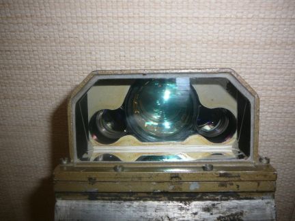
At the end of the left handle of the TKN-3M is a button to designate a target for the gunner, in the same way as the hunter-killer system in the T-54B using the TPK-1 periscope. When pressed, the turret turns at its maximum speed until it reaches the same angular position as the cupola. When designating targets for the gunner, the commander presses and holds both the right and left handle buttons to keep the cupola fixed on the target via the counter-rotation mechanism. Once the turret is slewed towards the target, the gunner will see the target, lay the gun, and then fire upon it. It is worth noting that the target designation button can be held down to slave the turret to the commander. Wherever he aims the reticle, the turret will follow.
The photo below shows the direction sensor, painted red, in contact with the three metal bands on the cupola ring above the golden toothed band. These metal bands interface with a roller inside the direction sensor, and the sensor detects the angular position of the cupola relative to the turret by detecting the direction in which the roller is deflected. The counter-rotating system is installed at the turret ring and transmits rotational energy from the moving turret to the cupola via a cardan shaft. The cardan shaft ends in a drive gear in contact with the toothed band around the circumference of the cupola ring. The drawing on the right below shows the counter-rotation mechanism and its connection to the turret ring.


Technologically, the TKN-3M was outstripped as early as 1965 by the TRP 2A independent panoramic sight installed on the Leopard 1, and by the highly advanced PERI-R12 panoramic surveillance and sighting system installed in the Leopard 1A4 beginning in 1974. Both of these devices were capable of a wide range of smoothly variable magnification settings and had powered traverse, and the secondary function as the sighting complex for the commander when he used the gunnery override mode. Having this ability in an independent surveillance device was a breakthrough for the late 60's, and many tanks would not have a similar feature until the late 80's or 90's.
The TKN-3M sight has a set of markings incremented in fixed angular mil values and a stadiametric rangefinder designed for the commander to measure the range to a typical NATO tank with a height of around 2.7 meters from a distance of 800 m to 3,000 m or 800 m to 3,200 m depending on the TKN-3 variant. For the T-72, these markings are not to be used as the primary method of rangefinding as the gunner has access to a much more precise optical or laser rangefinder, depending on the T-72 variant. Both of these are less sensitive to environmental factors.
Using the TKN-3M or TKN-3MK, it is entirely possible for the commander to see tank-sized targets from more than 3.0 kilometers if weather conditions and the geography of the battlefield allows for it, but in reality, conditions are almost guaranteed to be degraded in some way. The most difficult scenario would involve camouflaged targets hiding in foliage with minimal exposure and without moving.

The markings on the horizontal and vertical scales can be used to determine the angular distance between terrain features for creating range cards, to determine the necessary fire corrections for the gunner in elevation and azimuth, or to estimate the range to a target, among other uses. In the TKN-3M and TKN-3MK, the size of the increment between the long lines on both the vertical and horizontal scale is 8 mils, and the long lines are divided into two halves of 4 mils by a short line. The width and height of the cross hairs from the center to the nearest short line are 4 mils. In the drawing below, example (α) demonstrates the use of the vertical scale to obtain a reference measurement of a tree, which is 16 mils tall, and example (б) demonstrates the use of the horizontal scale to perform fire adjustment for the gunner. In this example, the shot landed 20 mils to the left of the target, and seeing this, the commander orders the gunner to adjust his point of aim to the right by 20 mils.


NIGHT VISION
To use the TKN-3M in the night vision mode, the only preparation needed is for the commander to plug the sight to a power outlet on the cupola and then power up the night vision unit by flipping the power switch. Once powered up, the commander can switch from the night vision channel to the daylight channel instantaneously. Switching to the night vision mode in the periscope viewfinder is done by opening the protective shutter of the night vision input window by turning a lever above the eyepieces of the sight, then flipping a selector switch on the right side of the periscope from "Д" to "Н". This switches the view in the eyepieces by flipping an internal mirror by 90 degrees, thus changing the optical path between from the daylight channel to the night vision channel. The switch is shown in the image below.

The diagram below shows the two choices. Diagram (a) on the left shows the path of the light from the aperture through the night vision system and into the eyepiece, while diagram (b) on the right shows the mirror flipped 90 degrees and the light from the aperture passing through the normal optical channel for daytime use.

In the passive mode of operation, the light intensifier tubes in the sight amplify the ambient light to create a legible image in lighting conditions as dark as a typical moonless, starlit night (0.005 lux). As the amount of light increases, the effective viewing distance increases. The image gain can be adjusted according to the brightness level to obtain the best possible image clarity. Officially, a tank-type target can be identified at up to 500 meters at 0.005 lux ambient light, but identifying the same tank should be entirely possible at slightly further distances in moonlit nights, though excess brightness cannot be tolerated as the image intensifier tube may be damaged from the power surge. To limit the intensity of the incoming light, the periscope features an internal diaphragm with a manual adjustment lever. The commander adjusts the lever to limit the amount of light entering the periscope when operating under high levels of illumination at night, as well as when checking the device in the daytime for calibration purposes. This allows the night vision channel to be used even during dawn and dusk lighting conditions.


The two most significant advantages of the passive imaging system is that no infrared light is emitted, unlike an active infrared imaging system, and the image intensifier system enables the commander to detect the minute amounts of visible light emitted from enemy IR spotlights and headlights from long distances.
The TKN-3MK is an updated variant with a Gen 2+ image intensifier system, producing an image of higher resolution and with no peripheral distortions, which was the main downside of the cascading tube system used in the TKN-3M. However, the passive viewing distance remained the same at 500 meters under the same lighting conditions stated before (moonless, starlit nights with ambient light levels of 0.005 lux), possibly due to being hamstrung by the 4.2x magnification of the optics. Gen 2+ image intensifiers differ from their 1st generation counterparts by the implementation of an MCP, a so-called "electron multiplier". The addition of an MCP substantially increases the amplification factor of the device compared to a 1st generation image intensifier, but the price of a 2nd generation image intensifier is also much higher. All T-72B tanks are equipped with the TKN-3MK. Sadly, even the latest modifications of the T-72B3 is also equipped with the TKN-3MK, which is entirely inappropriate for its time.

Besides the passive image intensification mode, the TKN-3M and TKN-3MK can be used in the active mode by turning on the OU-3GA2 or OU-3GK1 IR spotlight mounted on the rotating cupola. Inside the spotlight is a relatively low-powered incandescent lamp designed to run on 110 W when connected to the tank's electrical system.

The maximum distance at which a tank-sized target can be identified in the active mode is 400 meters, although the spotlight can illuminate objects much further away than that. This is an improvement compared to the 250-meter range provided by the older TKN-1S periscopes used on tanks like the T-54B, but by the 1970s, this level of performance was outdated. The main issue is the low resolution of the image. The active mode was to be used if observation was inadequate in the passive mode. Ideally, an entire engagement should be carried out without the use of the spotlight at all, as it is a very convenient unmasking signal revealing the location of the tank to enemy forces.
Without the infrared filter, the spotlight emits white light at 240 candelas. The infrared filter prevents all but approximately 0.001% of the light in the visible spectrum (360-760 nm) to pass through, and the light that passes through is at the higher end of the visible spectrum. As such, the spotlight emits a very faint red light with an intensity of around 0.24 candelas that can be perceived by the naked eye at close range when the OU-3 spotlight is activated in low light conditions. The intensity of near infrared light is much higher, of course. This light can be detected by the photosensor of a digital camera without an infrared blocking filter. The photosensor displays this infrared light - which is otherwise invisible - as pink light. This can be seen in the photos below, showing the OU-3 of a BRDM-2 (pictures from kmshik from the Gaz 69 forum).


When the OU-3 spotlight is used without the infrared filter, the periscope can be used at night in the daylight mode and the viewing distance can be further increased at the cost of exposing the location of the tank to all enemy forces, including those without night vision devices. This is permissible in certain circumstances, but it is not common.
Overall, the TKN-3M offers very poor night viewing capabilities compared to modern thermal imaging sights, but it was at least equally advanced as other devices of its type built in the 60's (the TKN-3 first appeared in 1964 on the T-62), and the use of image intensification technology was a novel feature up until the 70's, when the TKN-3M/MK was outstripped by more advanced Western passive image intensifying optics. The TKN-3M/MK was not replaced or sufficiently upgraded as the T-72 entered the 1980's.
The periscope aperture has a small wiper to clear it of rain and debris, as the photo below shows.

Without the infrared filter, the spotlight emits white light at 240 candelas. The infrared filter prevents all but approximately 0.001% of the light in the visible spectrum (360-760 nm) to pass through, and the light that passes through is at the higher end of the visible spectrum. As such, the spotlight emits a very faint red light with an intensity of around 0.24 candelas that can be perceived by the naked eye at close range when the OU-3 spotlight is activated in low light conditions. The intensity of near infrared light is much higher, of course. This light can be detected by the photosensor of a digital camera without an infrared blocking filter. The photosensor displays this infrared light - which is otherwise invisible - as pink light. This can be seen in the photos below, showing the OU-3 of a BRDM-2 (pictures from kmshik from the Gaz 69 forum).


When the OU-3 spotlight is used without the infrared filter, the periscope can be used at night in the daylight mode and the viewing distance can be further increased at the cost of exposing the location of the tank to all enemy forces, including those without night vision devices. This is permissible in certain circumstances, but it is not common.
Overall, the TKN-3M offers very poor night viewing capabilities compared to modern thermal imaging sights, but it was at least equally advanced as other devices of its type built in the 60's (the TKN-3 first appeared in 1964 on the T-62), and the use of image intensification technology was a novel feature up until the 70's, when the TKN-3M/MK was outstripped by more advanced Western passive image intensifying optics. The TKN-3M/MK was not replaced or sufficiently upgraded as the T-72 entered the 1980's.

As mentioned before, the TKN-3M sight depends on an OU-3GA2 incandescent IR spotlight for illumination when operating in the active infrared imaging mode. An inherent shortcoming to the usage of IR spotlights is that opposing forces using a similar night vision system can also see the beam of light along with its source. The SVD sniper rifle, for example, was fitted with the PSO-1 scope with a solar-powered rechargeable IR filter that gave the designated marksman or sniper the ability to see sources of active infrared illumination without the need for a large image intensification tube and a power source. Devices like this make it easy for the T-72 to be caught in an ambush at night by other tanks of the era like M48s, M60s, Leopard 1s, Chieftains, etc, although it must be said that the inverse also applies.
However, the OU-3 design is particularly flawed in this respect because it lacks an occluder. The lack of an occluder means that around half of the light from the spotlight is projected directly forward instead of into the parabolic reflector. As such, an enemy observer will not only see a circular patch of light. When observing a Soviet tank with its IR spotlight on, a large portion of the tank will be brightly illuminated. The additional illumination brings the minor benefit of lighting up the ground for the driver to see more clearly, so the common issue of speed control due to short visibility distance with the complementary IR periscope for the driver is slightly alleviated in battle conditions.
COMMANDER'S FIRE CONTROLS
None of the Soviet era T-72 models featured a set of firing controls for the commander. This feature only came on the recent T-72B3 modernization, equipping the commander to override the gunner entirely. He has a flatscreen display linked to the Sosna-U sight and the necessary controls for firing the main gun and the coaxial machine gun at his disposal in the form of a control unit, which includes a fixed handle with a thumbstick, trigger, autoloader controls, and more.
This arrangement provides the commander with the option capability that is no different from what most Western tanks already had for decades. These fire controls are part of the 1A40-4 fire control system. The resolution of the flatscreen display is not known directly, but it is reported that the Catherine-FC thermal imager has an image resolution of 754x576 so it should be safe to assume that the display is configured for this.

Control of turret traverse and gun elevation is accomplished using the thumbstick. The decision to use a thumbstick was presumably because a full joystick could not be easily manipulated with precision if the operator's body and arm were rocking around while the tank travelled over rough terrain. Under such circumstances, the thumb would remain completely stationary if the hand was securely gripping a fixed handle. The commander's index finger rests on the trigger button behind the handle. The control unit also allows the commander to activate the autoloader to load any ammunition type except guided missiles.


Control of turret traverse and gun elevation is accomplished using the thumbstick. The decision to use a thumbstick was presumably because a full joystick could not be easily manipulated with precision if the operator's body and arm were rocking around while the tank travelled over rough terrain. Under such circumstances, the thumb would remain completely stationary if the hand was securely gripping a fixed handle. The commander's index finger rests on the trigger button behind the handle. The control unit also allows the commander to activate the autoloader to load any ammunition type except guided missiles.

RADIO COMMUNICATION
All T-72 tanks were equipped with a radio station. It would be installed on the turret ring next to the coaxial machine gun and quite conveniently in front of the commander's seat. To work with the radio, the commander could simply reach forward. The ease of access to the radio is characteristic of Soviet tanks, as in a number of foreign tanks with a radio fitted in the turret bustle, the commander has little direct interaction with the radio and instead uses a separate control panel which only permits him to switch between frequencies.
Various radio stations were used across the different T-72 models operated by the Soviet, and then Russian armies as shown in the following timeframes.
- 1973-1984: R-123M transceiver with R-124 intercom
- 1984-2012: R-173 transceiver, R-173P receier, R-174 intercom
- 2012-present: R-168-25UE-2 transceiver, R-168 AVSK-B intercom
Each crew member was connected to the intercom network of the tank, allowing half-duplex communications between all three crew members. The radio is also connected to the intercom system, so that all crew members may listen at the same time, or one crew member can broadcast at a time. Normally, only the tank commander uses the radio, while the other two men only listen and respond to orders from the commander via the intercom. Additionally, a tank rider can plug into an intercom connector socket located between the commander's cupola and the shell casing ejection port on the rear of the turret, whereby he can talk to the crew. An additional tanker helmet and connector set is included in the standard equipment of the tank, and can be left on the turret for tank riders to use.
Both the radio and intercom systems were directly routed to the laryngophone of the headset and the control box.
R-123M TRANSCEIVER

The T-72 and T-72A were originally supplied with an R-123M analogue radio transceiver station. At the time the T-72 entered service, the R-123 was the standard radio system for all armoured vehicles since the 1960's, and the R-123M model was a modernized variant. It replaced the R-113. The R-123M has a total operating frequency range of between 20 MHZ to 51.5 MHZ, which is wider than the R-113. The operating frequency range was split into 2 sub-bands, 20-35.756 MHz and 35.75-51.5 MHz. It could be tuned to any frequency within those limits when set to the manual tuning mode, or the commander could quickly switch between four channels with preset frequencies for platoon-level communications. It takes several seconds for the mechanism to switch between frequencies, and the channel number is displayed on an illuminated display on the top right corner of the radio. This instructional video shows the R-123 in use. Communication is possible with low level infantry radio sets, including the R-105M, R-108M, R-109M, R-114 and R-126.
The transceiver unit of the R-123M measures 428x239x222 mm, and the power supply unit is 210x166x220 mm.
A whip antenna was installed together with the radio, adjustable to 4-meter, 3-meter, 2-meter and 1-meter increments. It had a nominal range of between 16 km to 50 km depending on the terrain, weather conditions and noise levels, but according to the manual, with the whip antenna fully deployed to its 4-meter length, a T-72 travelling at 40 km/h with the radio noise suppressor turned on can expect a broadcast and reception range of at least 13 km or at least 20 km without the noise suppressor. If the antenna is set to the 1-meter length, the range is drastically reduced.
As there is only one transceiver, the radio is limited to half-duplex communication on one frequency at a time. This is a trait it shares with the majority of vehicle radios of the time, including models such as the AN/VRC-12 (or AN/VRC-64) radio used in American tanks up to the Abrams series during the Cold War. These were all conventional transceiver sets limited to half-duplex communications on one frequency at a time. Command tanks would have an additional R-442/VRC receiver to permit the commander to listen on one frequency (simplex) while communicating in half-duplex mode on another using the transceiver.
The R-123 was designed with two deliberate features for increased jamming and noise immunity, which were its increased transmission power of 20 Watts, and its choice of operating frequencies. The increased transmission power was responsible for the increased range of the R-123 and it improved signal reception for receivers, but the increased power also improved the resistance to interference, as more powerful jamming would be required to suppress its signals. Compared to the standard SEM-25 tank radio used in the Bundeswehr which had a transmitting power of up to 15 W, and the AN/VRC-12 tank radio used in the U.S military since 1965 which had a transmission power of 30 W, the power of the R-123 is moderate. Moreover, the choice of the operating frequency range had a significant overlap with the operating frequency range of foreign radio systems. In the US Army, the AN/VRC-12 tank radio operated in the 30-75.95 MHz frequency range, the British used the VRC 353 with a 30-75.975 MHz frequency range, while German tanks were equipped with the SEM-25 radio station, which had a 20-69 MHz frequency range. This made it infeasible for enemy forces to utilize indiscriminate or barrage jamming - which was previously possible against the R-113 due to its narrow 20.00-22.375 MHz frequency range - as the range of possible frequencies was too large, and even if it were attempted, indiscriminate jamming would impair their own radio communications.
The R-123 had a relatively novel glass prism window at the top of the apparatus that displayed the operating frequency by projecting figures from a rotating scale. It had 1,261 possible frequency settings within its operating range, with an increment of 25 kHz. By having illuminated frequency and channel displays, the design of the R-123 was ideal for the darkened interior of a tank. Moreover, another merit of the R-123 was its modular design that enabled it to be repaired quickly by simply swapping out individual modules rather than working on individual components.
For T-72M and T-72M1 tanks exported outside of the Warsaw Pact, the R-123M was the most advanced option available. By the time T-72 export gained traction in the 1980's, the Soviet Army had switched to the R-173 digital radio with data encryption as this had become the norm for modern armies.
R-130M RECEIVER

T-72K and T-72AK command tanks, used on the battalion and regimental levels, had an additional R-130M radio receiver to permit long range one-way communication with the regimental or divisional headquarters. In this way, if the battalion or regiment commander could not set up a field command post, the command tank could provide the basic essentials needed for operational coordinations.
The R-130M was installed behind the commander's seat, with the commander being the radio operator, appropriately enough. The operating frequency range of the radio is 1.5-10.99 MHz. It is split into 10 sub-bands, with 95 frequency settings per band. It has its own whip antenna, adjustable to 4-meter, 3-meter, 2-meter and 1-meter increments. Command tanks can therefore be identified by their two antennas. The image below, showing a Georgian T-72 SIM-1 with the two antennas characteristic of a command tank.

With the basic 4-meter whip antenna, the R-130M permits communications out to a range of up to 50 km, both stationary and on the move. If the 10-meter mast antenna is deployed, it is possible to increase the reception range out to 350 km, but the tank must be stationary as the mast antenna must be secured with guy wires.

When working with the mast antenna, the AB-1 petrol auxiliary power unit (APU) in the tank is used to supply power to the radios instead of the engine, or to recharge the batteries if needed. It is installed to the right of the driver. The starboard side conformal fuel tank and ammunition rack was modified to accommodate it, having a reduced capacity of petrol to supply the generator exclusively and lacking slots for ammunition. Because of this, the ammunition capacity of the tank is reduced by 7 shots.
The APU was designed to allow the tank to operate its long range radio equipment for an extended duration (up to 4 hours continuously) without having the noise of the tank engine interfere with communications. The AB-1 was installed in the T-72K, T-72AK and T-72BK.
R-173 TRANSCEIVER

Beginning in 1984, the R-123M was replaced by the R-173 digital radio transceiver. The R-173 can be used to to transmit and receive voice signals for normal communications, or transmit and receive encrypted analogue and digital data. The radio operates in a frequency range of 30-75.999 MHz with a frequency increment of 1 kHz, providing a much wider frequency range than the R-123. It could be programmed to receive and broadcast in 10 programmable preset frequencies, with a frequency switching time of 3 seconds. According to the 1984 paper "Развитие Танковой Радиосвязи В Послевоенный Период" (Development of Tank Radio Communications in the Postwar Period), the expansion of the operating frequency range was driven by the desire to combine the operating frequency ranges of domestic radio stations with the frequency ranges of the radios of the hypothetical enemy.
It had an electronic keypad for entering the desired frequency and a digital display to show the frequency value, and again, it is worth noting that an illuminated display is ideal for the dark interior of a tank. The dimensions of the R-173 transceiver unit are 428x240x222mm. Thanks to the use of integrated circuits in the transceiver, the volume of the device was drastically smaller than the previous radio transceivers, making it possible to integrate the power supply unit into the same casing as the transceiver, occupying the block to the right of the radio. Thus, the space previously allocated to the power supply unit was freed up, allowing an additional R-173P receiver to be fitted. All T-72B tanks are fitted with a set of both an R-173 and R-173P as part of the radio station. It is also possible for very late production T-72A tanks to also have the new radio station. At the time the R-173 was introduced, the radios used in NATO tanks were still of the previous generation - or in other words, analogue devices with no built-in encryption. That said, there was no real gap in favour of the Soviet Army, because in 1984, the same year the R-173 entered service, the standard SE-412 tank radio station used in the Bundeswehr received an add-on voice encryption unit.
This video shows an R-173 in use by an amateur radio operator.
R-173P RECEIVER

Encrypted voice data received by the R-173P can be decrypted, and it operated in a frequency range of between 30-75.999 MHz like the R-173 radio. It also has 10 programmable preset frequencies. The R-173P receiver and the R-173 transceiver can be used simultaneously so that the commander can transmit and receive on the R-173 on one frequency (in the half-duplex mode) while also receiving uninterrupted voice communications on another frequency (in the simplex mode) via the R-173P.
This capability was previously only provided for command tanks, which would often use the standard tank radio for communications with subordinates and use the additional long range radio as a continuous link to the headquarters of the next higher level, through which the battalion or regiment commander could receive orders. By providing a transceiver-receiver set to every tank, it became possible for Soviet tank platoons and companies to set up better-coordinated tactical networks. For instance, a platoon leader could use his R-173P receiver to maintain constant communication with the company leader while also delegating tasks to the two subordinate tanks in his platoon, while the two subordinate tank commanders in the platoon could use their R-173 transceivers to talk with each other while using their R-173P receivers to receive orders from the platoon leader. If this configuration is unsuitable, different network structures could be arranged depending on the circumstances. This was a capability that was previously found on standard tanks with the German SEM-25 radio of the Leopard 1 and early Leopard 2 models, or in M60 unit leader tanks equipped with an additional receiver.
Thanks to its compactness, the R-173P was installed just next to the R-173, in the space previously occupied by the power supply unit. The photo below of a T-90 interior shows the location of the R-173P.

R-168-25UE-2 RADIO SET

To keep up with the increasing sophistication of electronic warfare threats, a replacement for the R-173 was sought after, leading to the creation of a universal R-168 radio system to equip all levels of a division with a single standardized radio transceiver-transceiver set. It was launched into service in the 2000's, but has been slow to proliferate, with mass production starting only in 2005. The most recent large scale modernization drastically increased the share of R-168 radios in the Russian Army, with armoured vehicles receiving the new radio during scheduled repairs. Tanks and other armoured vehicles received the R-168-25UE-2 model. All T-72B3 tanks are equipped with this radio station, including unit leader tanks at the company, battalion and regiment levels.
The R-168-25UE-2 consists of two R-168-5UTE-2 transceivers plugged into a central hub which connects the two transceivers to the electrical and communications network of the tank. The radio station measures 428х248х239 mm. The entire radio station is a self-contained unit, so the complete station is the same size as a single R-173. Because of this, additional space was freed up in the commander's station by the omission of a separate receiver unit.
With an operating frequency range of 30-107.975 MHz and a frequency step of 25 kHz, the R-168-25UE-2 has a much wider operating band than previous radio sets, but because the minimum frequency is 30 MHz, full interoperability is only possible with the R-173 series and not the R-123 series, which has a minimum frequency of 20 MHz. It is entirely impossible to communicate with R-130M radios, as those work in a narrow frequency band of 1.5-10.99 MHz. When using the basic BShDA whip antenna, the tank has a transmitting and receiving range of 30 km on the move, and when using the ShDAM mast antenna, the range is extended to 60 km, although the tank must be halted. This meant that the R-168 also had the capability to serve as a replacement for R-130M radios for battalion and regimental-level command tanks thanks to the 60 km range limit, thus removing the need for dedicated command tanks, increasing the available space in the battalion and regiment commanders' tanks, and simplifying production to a single T-72B3 model. The radio enabled the T-72B3 to operate in the new network-centric data sharing system currently implemented in some Russian units.
Besides the updated communications hardware, the tank's intercom and radio control box was also augmented with new digital control panel shown below. The display is illuminated, and an optional backlight for the buttons can turned on.

The R-168 series not only had data encryption but also featured frequency hopping for noise immunity in the presence of radio interference. It can produce frequency hops 100 times a second, and can transmit or receive encrypted voice or data at 1.2-16 kb/s. The radio has several modes of operation: fixed frequency, pseudo-random tuning of the operating frequency, adaptive communication, scanning reception at 8 preselected frequencies, work with a noise suppressor, retransmission, manual and automated recording of radio data from the device input of radio data with an optical interface or from an external computer, emergency erasure of radio data, transmission and reception of circular, address and tone calls, network control from an external computer via a standard RS-232C socket, voice informant of operator actions, dialogue mode, automated performance monitoring, simplex or two-frequency simplex at one of 8 preselected frequencies, and simultaneous transmission of voice and data.
For the defence of the tank and crew against enemy infantry in close-in combat, there is a single assault rifle, either an AKMS or AKS-74, stowed in the turret with 300 rounds in 10 magazines. It is accessible to the commander, who is normally responsible for using it if the need arises, but the magazines are stowed on both sides of the turret. There is also a box with 10 F-1 defensive hand grenades, also accessible from the turret. The PKT coaxial machine gun in the tank may also be used as an improvised infantry machine gun by dismounting it and firing it with the backup mechanical trigger.


If the commander wishes, he can hand over the assault rifle to the gunner, and the gunner can load it with the magazines stowed at his station.


GUNNER'S STATION

The gunner is seated on the left side of the turret. He is provided with a single forward-opening hatch. Its most distinctive feature is the smaller circular port hole at its center for the installation of a snorkel. The port hole can also be opened to increase the airflow in the tank in conjunction with the switching of the engine air intake system from the external intake to the crew compartment intake. The hatch is spring loaded to assist the gunner when opening it and can be locked in the forwards position, like the commander's hatch. It is locked in place with a simple rotating latch. There is a single TNPA-65 periscope embedded in the hatch, facing to the left.

Measurements on a T-72M showed that the gunner's hatch is 584mm (23 inches) wide and 354mm (16 inches) long in radius, so like the commander's hatch, it meets the U.S Army human engineering size requirements for a 95th percentile male in light clothing. For comparison, the loader's hatch on an M60 is 22.5 inches wide and 15 inches long in radius.


The gunner is responsible for all of the equipment in the tank related to its firepower, including the autoloader, stabilizer, cannon, the sighting devices and their associated instruments. The gunner's station is dominated by the massive GPS (Gunner's Primary Sight) which completely fills the space between the gunner and the front wall of the turret. The gunner's station is the most cramped position in the T-72, and even more so if he is wearing winter clothing. However, it would be a mistake to consider the cramped nature of the gunner's station as a unique and defining feature of the T-72 or to exaggerate it beyond what it really is. As a whole, the T-72's turret does indeed have a much smaller volume than most tanks, but the space delegated to the gunner is very much on par with its contemporaries.

The gunner's seat, which consists of a cushion and a backrest attached to a base, is permanently fixed. Beginning with the T-72B, the seat had a semi-permanent fixed position. The seat can only be adjusted backwards or forwards by unbolting it from the mounting frame and then bolting it onto a set of two alternative holes provided on the frame, but this is to be done once by the gunner of the tank and then left alone. In all T-72s, the backrest can be swiveled between three different positions. The main reason for swiveling the backrest is so that the gunner doesn't sit with his lower body twisted to the right, if the gunner doesn't simply rest his left foot on the autoloader carousel cover for whatever reason, because the folding footrest is offset to the right. The gunner can sit in a normal posture with his feet resting flat on the autoloader carousel cover, or with his legs outstretched, resting on either thecarousel cover or his footrest. The seat can be folded up and to the right to be flush against the recoil guard, but this requires the backrest to be removed by lifting it from its socket on the seat base. Folding the seat away creates a space on top of the autoloader carousel for the guner to sleep, or simply to widen the driver's crawlspace if he were evacuating the tank through the turret, especially if the turret is turned to the right.


According to an Indian pilot study of locally built T-90S tanks, titled "Ergonomics analysis of gunner station of armoured combat vehicle (ACV)- Tank T 90S with special reference to seat, visual sighting system and musculoskeletal discomfort: A pilot study", the height of the gunner's seat from the carousel cover is 150mm. However, the seat is of a local modification, lacking the foam cushion of the original seat, instead having a woven jute seat with a canvas cover for durability reasons. The thickness of this seat should be much less than the original type, so it is likely that in an original T-72, the height of the gunner's seat is more than 150mm above the carousel cover.
The two images below show two versions of the seat mounting frame found in the T-72. Most are of the design shown on the right, with T-72B and T-72S tanks using a slightly modified variant. The rear end of the seat mounting frame is fixed to the rear base of the turret, near the turret ring.


The front end of the frame is secured to the front of the turret via the a heavy steel bracket, shared with a few electric components. The middle of the frame is supported by the gunner's fixed recoil guard, which is bolted to the turret ceiling. The gunner's fixed recoil guard has four gun elevation marks for visual reference. These are: 0°, 3.5° (labelled as the loading angle), 10° and 13°. By referring to these marks, the gunner can manually elevate the gun to specific angles for certain tasks.

The width of the gunner's station, as measured at the position of the gunner's torso, is 571mm (22.5 inches). Because the gunner's seat is slightly behind the widest point of the turret ring, he has less shoulder room than the commander when seated normally. When the gunner leans forward, as he would when using the sights, the shoulder room increases. The height of the station is 890-914mm (35-36 inches) when measured from the seat cushion to the ceiling of the gunner's hatch. The variation is due to the slant of the hatch, so that the height is less toward the left side and more toward the right side. This meets Soviet requirements for a driver's station (driver's station height must be 850-900mm), which is the appropriate point of reference due to the seated posture of the gunner. Otherwise, the standard for a gunner is 1,300mm, but this is because the gunner is assumed to be seated in a normal posture with a high popliteal height.
Refering again at this table from "Human Factors and Scientific Progress in Tank Building" by M.N. Tikhonov and I.D. Kudrin, we can see that the space afforded to the gunner is 0.495 cubic meters - well above the minimum of 0.44 cubic meters for a seated man in an NBC suit to inhabit and work in his station. This was an improvement over the T-55 which gave its gunner only 0.395 cubic meters of space. As mentioned before in the "Commander's Station" section of this article, the slanting roof of the turret over the gunner's station has the opposite effect that the commander's cupola had on the internal height available for habitation. To counteract this, the height of the seat was reduced such that the gunner was practically seated directly on top of the autoloader carousel cover. However, his legroom remains the same as the commander's. The gunner's seat is mounted on a frame attached to the back of the turret. The original design of the frame is shown below in the drawing on the right, and it was changed in the T-72B, shown on the left. From the seat backrest to the footrest, the gunner's station has between 1.1 to 1.2 meters of space, exceeding the average figure of 1 meter for an average male with a height of 1.7 meters.
It can be seen in the drawing below that for a gunner of average height, his head would be pressed up to the turret ceiling if he is operating the night sight offset to the left of the primary sight. His feet would be resting on a fold-out footrest, but he can simply extend his legs completely in the turret due to the two-man layout.

In terms of space and comfort, the gunner's station in a T-72 is quite adequate for crew members of average height and size, though there could be problems for people of extreme height, as the clearance provided for the gunner's head is not large. On long marches, both turret occupants may simply sit on the turret roof instead of remaining inside the tank. In this respect, the T-72 has a notable ergonomic advantage over many tanks in that the gunner has his own hatch and he can exit whenever he likes to sit on the roof or to stand upright. The ability to do this makes a drastic difference to the gunner's health and comfort in hot weather conditions, because the internal temperature of the tank will be much greater than the ambient air temperature owing to additional heating from the steel walls of the turret and hull, exposed to direct sunlight. In tests with T-55 and T-62 tanks, for example, the internal air temperature in the fighting compartment would be 6-9 degrees higher than the ambient air temperature at 21°C and 28°C when forced ventilation is not used.

In terms of space and comfort, the gunner's station in a T-72 is quite adequate for crew members of average height and size, though there could be problems for people of extreme height, as the clearance provided for the gunner's head is not large. On long marches, both turret occupants may simply sit on the turret roof instead of remaining inside the tank. In this respect, the T-72 has a notable ergonomic advantage over many tanks in that the gunner has his own hatch and he can exit whenever he likes to sit on the roof or to stand upright. The ability to do this makes a drastic difference to the gunner's health and comfort in hot weather conditions, because the internal temperature of the tank will be much greater than the ambient air temperature owing to additional heating from the steel walls of the turret and hull, exposed to direct sunlight. In tests with T-55 and T-62 tanks, for example, the internal air temperature in the fighting compartment would be 6-9 degrees higher than the ambient air temperature at 21°C and 28°C when forced ventilation is not used.
In the event of an internal fire, the entire crew can bail out through their own hatches with no fuss. This is quite unlike tanks like the T-55, Leopard 1, Abrams, or indeed, any other manually-loaded tank except for a few oddball designs like the M60A2 as the gunner is usually not provided with his own hatch. On long marches, he might be forced to stay put in his decidedly cramped station for hours at a time. This is not the case for the gunner of a T-72.

Like in most tanks, the gunner's station in the T-72 is the most cramped, but it is important to note that in the vast majority of manually loaded tanks, the gunner is not provided with a hatch of his own and as such. If a T-72 gunner began to feel uncomfortable for any reason, he can open his hatch and sit on the roof, or just stand on his seat and stretch. Additionally, in a typical manually loaded tank, if the commander were incapacitated or killed, the gunner would have to squeeze through the commander's body or shift it aside in order to bail out through their shared roof hatch. This is also not a problem for the T-72.

Ventilation is provided by a DV-3 fan, like in the commander's station. It is more than enough in European climates where temperatures are usually around 20° C (68° F) or less as it is a relatively powerful 5.2 W fan, but the cooling capacity may not be enough for summer weather let alone in hot, desert regions averaging 30°C to 40°C. In summer conditions, the internal temperature is drastically higher than the ambient temperature due to the heating of the tank from the sun, making it necessary to blow great quantities of air through the crew compartment to cool down. In such weather, the fan is only useful for increasing air circulation to stave off heat strokes, and little else, as the bulk of the ventilating task is shouldered by the ventilation supercharger or the engine cooling fan, if the engine partition port is opened. Still, it is unquestionably better than tanks that do not provide any personal ventilation at all. Several tanks made during the 60's and 70's lacked this ostensibly minor amenity.
The gunner is provided with a master control panel, with which he can control some lights, the ventilation supercharger, the emergency firefighting discharge button, and other functions in the tank. It is very similar to the commander's master control panel, but has a few different controls and lacks the emergency engine stop button and the autoloader rammer control switch used for setting the fuse on HE-Frag shells, which is not done by the gunner.

Like in most tanks, the gunner's station in the T-72 is the most cramped, but it is important to note that in the vast majority of manually loaded tanks, the gunner is not provided with a hatch of his own and as such. If a T-72 gunner began to feel uncomfortable for any reason, he can open his hatch and sit on the roof, or just stand on his seat and stretch. Additionally, in a typical manually loaded tank, if the commander were incapacitated or killed, the gunner would have to squeeze through the commander's body or shift it aside in order to bail out through their shared roof hatch. This is also not a problem for the T-72.
Ventilation is provided by a DV-3 fan, like in the commander's station. It is more than enough in European climates where temperatures are usually around 20° C (68° F) or less as it is a relatively powerful 5.2 W fan, but the cooling capacity may not be enough for summer weather let alone in hot, desert regions averaging 30°C to 40°C. In summer conditions, the internal temperature is drastically higher than the ambient temperature due to the heating of the tank from the sun, making it necessary to blow great quantities of air through the crew compartment to cool down. In such weather, the fan is only useful for increasing air circulation to stave off heat strokes, and little else, as the bulk of the ventilating task is shouldered by the ventilation supercharger or the engine cooling fan, if the engine partition port is opened. Still, it is unquestionably better than tanks that do not provide any personal ventilation at all. Several tanks made during the 60's and 70's lacked this ostensibly minor amenity.
The gunner is provided with a master control panel, with which he can control some lights, the ventilation supercharger, the emergency firefighting discharge button, and other functions in the tank. It is very similar to the commander's master control panel, but has a few different controls and lacks the emergency engine stop button and the autoloader rammer control switch used for setting the fuse on HE-Frag shells, which is not done by the gunner.

For general visibility, the gunner is provided with a single forward-facing TNP-165A periscope and another TNPA-65A periscope embedded his hatch, facing to the left. The TNP-165A periscope provides 71 degrees of vision horizontally and 33 degrees of vision vertically, and as mentioned before, the TNP-65A provides 140 degrees of vision horizontally and 35 degrees of vision vertically.
The TNP-165A is placed facing forward for the gunner to gain a wide view of his surroundings with the help of the rotating turret, to check the orientation of the gun barrel, and to make sure that the gun barrel is elevated safely when the tank is entering a ditch or overcoming some obstacle. In the daytime, the periscopes are also sources of light. It provides a field of view of 74 degrees horizontally and 35 degrees vertically. The design of the TNP-165A periscope is particularly noteworthy because it was created specifically for the gunner's stations of tanks. Its lower prism is shaped with an offset angle of 20 degrees so that the angle of the viewing window is intended for an observer below the normal eye level. This is because the eyepiece for the gunner's primary sight is already placed at the eye level of the gunner and a forward-facing periscope must be above it. As such, the gunner would have to be looking up to use the periscope.
Because the gunner does not lean forward with his eyes close to the viewing window when using the TNP-165A periscope, the danger of harm to the gunner's eyes from powerful bullets or fragments penetrating the periscope was very low. Additionally, a layer ballistic glass was laminated to the eyepiece to prevent glass fragments from being released into the crew compartment.

Most importantly, having the forward-facing TNP-165A periscope allows the gunner to more effectively use the tank from a turret-down status. The TPD-2-49 or TPD-K1 primary sight is periscopic so the gunner will have no trouble looking over the crest of a hill or a berm when the tank is hiding in a turret-down position. When the commander spots a target, he can designate it using the TKN-3 optic and the turret will slew over to point at it. The gunner will be able to see the target through his primary sight, lase it, and prepare to fire. Once the commander gives the order for the driver to move forward, the gunner can immediately open fire once the muzzle of the cannon clears the crest of the hill or berm and the FCS confirms that the cannon and the sight are aligned. However, the primary sight has an 8x magnification, so the gunner cannot see if the muzzle has gone over the crest of an obstacle from that alone. This is where the TNP-165A is particularly useful as it allows the gunner to independently verify the position of the cannon barrel without the commander's assistance.
The TNPA-65A periscope installed in the hatch provides the gunner with an additional outlet to view the outside world. One of the common issues in turreted tanks with a conventional seating arrangement is that the commander's station is offset from the centerline of the turret, so even if his cupola provides him with good all-round vision, the adjacent side of the turret will block his view and create a large dead zone. Tanks with human loaders usually provide the loader with a periscope to cover this dead zone, but since the T-72 only has the gunner sitting adjacent the commander, he is the one who has a periscope. A benefit of this arrangement is that the gunner can afford to be less dependent on the commander, and another benefit of having the TNPA-65A facing to the left is that the gunner can see for himself if there are any obstacles on the left side of the tank so that he can determine if it is safe to traverse the turret. This may be important when the tank is fighting in a densely forested area or in urban areas. The commander would be responsible for checking the right side of the turret, of course. Having a good view of the left side of the turret. The view from both the TNPA-65A and the TNP-165A can be seen in this video from the inside of a T-72B3.

In a more general sense, the two periscopes are also useful in that the gunner gains a sense of spatial awareness. This gives the gunner a wide view of the terrain ahead of the turret which is important as the primary sight has a fixed 8x magnification with no reduced magnification setting like the earlier telescopic TSh2-22 of the T-54 and TSh2B-41 of the T-62 (3.5x or 7.0x). Having some spatial awareness may also help to prevent motion sickness.
 |
| 1A40-1 sighting complex and 1K13-49 night vision/auxiliary sight |
As you can see in the photo above, the gunner is supplied with a duplicate of the commander's master control panel. Besides being able to initiate the fire control system, control the ventilation, turn on the lighting system, and much more, having the master control panel gives the gunner complete control over most of the electrical equipment in the tank, and also enables the gunner to set the fuse on a HE-Frag shell in lieu of the commander if necessary. This means that the T-72 can theoretically be operated with only a 2-man crew with a minimal loss in combat capabilities. This may be useful when a tank company or battalion is understaffed and there are no sufficiently qualified substitutes for the tank commander's position, however unlikely that may be. Of course, this capability is also largely thanks to the omission of a human loader.
Beginning in 1979, the T-72A began to receive the 902A "Tucha" smoke grenade discharge system. The 902A is distinguished from the 902B and 902V variants in having 12 grenades rather than 8 and 6 respectively. Note that the suffix does not have any specific meaning, and is simply alphabetical ordering in the Cyrillic alphabet ("А, Б, В" is equivalent to "A, B, C"). The gunner is in charge of using the system, but usually follows the instructions of the commander when doing so. Referring to the photo above, the control box for the system is located to his immediate left, at the gunner's elbow.
The control box splits the bank of 12 grenade launchers into 3 groups. Using this control box, he is able to deploy smoke grenades from one of three launcher groups individually or in a salvo of up to four grenades at once. The toggle switches marked (4) in the drawing below are to individually turn on the three grenade launcher groups, and with the selector dial marked (3), the gunner can select how many grenades to fire with each press of the button marked (1). According to the manual, the groups are to be selected individually, and when one group is switched on, the others should be switched off. If, for example, wide smokescreens are needed, then the selector dial can be preset to fire four grenades at once, and the gunner cycles from groups 1 to 3 with each salvo. The control box may be preset prior to combat, or the commander can make a decision to order the gunner to use a custom setting if the circumstances demand it, even firing grenades individually and traversing the turret to create distributed smokescreens.

When the 902B system was implemented on the T-72AV and T-72B to replace the 902A, the number of grenades was reduced to 8, but the same control panel was used. The only difference is that the toggle switch for group '3' was disconnected. The grenades in the 902B system remained split into two groups of four grenades each.
The large dial on the L-shaped box seen between the TPD-K1 eyepiece and the gunner's control handles is the AZ-172 autoloader control box. The autoloader can be toggled between the manual or automatic operating modes and the ammunition type can be selected by the gunner. The gunner triggers the autoloader to load by flicking the toggle switch on the underside of the control box to the left. The switch is directly behind and slightly above the left thumb of the gunner when he is grasping the hand grips of his control handles, so after each shot, if the gunner desires to load another round of the same type, he can activate the autoloader by simply raising his left thumb without needing to take his eyes off the eyepiece of the sight. When the dial is switched to a different ammunition type, the mechanical ballistic computer in the sight is electronically set to the ballistic cam of the corresponding ammunition. As such, if the gunner wishes to switch to a different ammunition type but already has a shot loaded, he should fire the shot that is presently loaded before selecting the next type and pressing the load button, so as to retain the ballistic solution calculated by the sight.

The large dial on the L-shaped box seen between the TPD-K1 eyepiece and the gunner's control handles is the AZ-172 autoloader control box. The autoloader can be toggled between the manual or automatic operating modes and the ammunition type can be selected by the gunner. The gunner triggers the autoloader to load by flicking the toggle switch on the underside of the control box to the left. The switch is directly behind and slightly above the left thumb of the gunner when he is grasping the hand grips of his control handles, so after each shot, if the gunner desires to load another round of the same type, he can activate the autoloader by simply raising his left thumb without needing to take his eyes off the eyepiece of the sight. When the dial is switched to a different ammunition type, the mechanical ballistic computer in the sight is electronically set to the ballistic cam of the corresponding ammunition. As such, if the gunner wishes to switch to a different ammunition type but already has a shot loaded, he should fire the shot that is presently loaded before selecting the next type and pressing the load button, so as to retain the ballistic solution calculated by the sight.
Two variants of the control box exist. The older model has a green signal lamp to indicate that a round has been loaded and a red signal lamp to indicate that there is a shell casing stub in the ejection mechanism. The newer model has a backlit display with with the same two messages: a red signal alerts the gunner that there is a shell casing stub in the ejection mechanism, and a green signal alerts the gunner that a round has been loaded.


This control box can be found on tanks that are equipped with the TPD-2-49 and the TPD-K1 sights. A L-shaped space was left empty on both sights at the same location for this control box and for a control box of the same function in the T-64. The earliest T-72 tanks leaving the factory in 1973 and 1974 had a different autoloader control box placed under the communications relay box and next to the autoloader ammunition indicator. This older control box was used to select the ammunition type and toggle between the manual and automatic operating modes, but was probably not as convenient for the gunner to use simply because it is physically further away from all the other controls in front of him. The 'load' button was on a separate box placed next to the TPD-2-49 sight, which required the gunner to take his right hand off the hand grip of his control handles to use. The photo on the left below shows the 'load' button and the photo on the right below shows the control box. Functionally, the gunner's controls were still the same, only that the L-shaped shaped was left unoccupied. The old control box was plugged into the same socket. It may have been only a limited edition release to fill out the orders until the final control box design could begin mass production.


All of the control boxes have the same dial settings. The first two settings from the left are "load" and "off", and the rest are settings to select HE-Frag, APFSDS, and HEAT. The "load" setting is used when replenishing the autoloader carousel and the "off" setting turns off the autoloader.
The T-72B uses a different autoloader, sometimes referred to as the AZ-184, and the control box is also different as a result. With the introduction of a new ammunition type, the new control box has an additional option on the ammunition selector dial: missiles. Externally, the only detail to differentiate the new control box from an older one is the addition of a new setting on the ammunition selector dial. The T-72B3 features a modification of the AZ-184 autoloader which accommodates new APFSDS ammunition, and it can be seen in the updated control box. The new control box retains a similar layout as the previous model and is functionally identical.

The autoloader control box can be used to set the autoloader to automatic operation or manual operation. Setting it to manual operation mode enables the crew to manually load the gun with partial assistance from individual components of the autoloader, such as the chain rammer, or to manually load the gun entirely by hand. If the crew intends to load the cannon manually, setting the autoloader to the manual mode is mandatory as it allows the sighting complex recognize the readiness of the cannon once a shell is loaded.
The gunner is also provided with an autoloader ammunition indicator. The indicator is rather crude, even for its time, as the indicator display is based on simple milliammeter technology. Due to the small size of the indicator pin, it may be difficult to easily see the indicated number in a high intensity situation. As usual, the indicator has an internal light so that it can be read when all of the tank's hatches are closed.

The indicator does not have any selectors or dials on its own housing. Rather, it works in conjunction with the autoloader control box. When the gunner selects an ammunition type on the dial on the autoloader control box, the ammunition indicator automatically displays the ammunition reserve for that ammunition type currently stowed in the autoloader carousel. The number of empty slots in the autoloader carousel is determined by setting the ammunition selector dial to the "Load" position. This is useful when determining if there is an imminent need to replenish the autoloader carousel. The ammunition indicator only goes up to eleven, so if the number of rounds for any ammunition type exceeds eleven, the exact number of rounds can only be determined by finding out the number of rounds of the other ammunition types and the number of empty slots in the carousel.
Besides the autoloader controls, there is also a turret azimuth indicator, installed just next to the manual turret traverse handwheel. It is a part of the horizontal turret drive mechanism.


The indicator is akin to a clock, with an hour hand and a minute hand. The hour hand is mainly a tool of convenience as it shows the direction the turret is pointing to, but it is also an important tool for laying the gun for indirect fire. The minute hand is read with the hour hand to obtain a precise reading of the orientation of the turret for indirect fire purposes.


This control box can be found on tanks that are equipped with the TPD-2-49 and the TPD-K1 sights. A L-shaped space was left empty on both sights at the same location for this control box and for a control box of the same function in the T-64. The earliest T-72 tanks leaving the factory in 1973 and 1974 had a different autoloader control box placed under the communications relay box and next to the autoloader ammunition indicator. This older control box was used to select the ammunition type and toggle between the manual and automatic operating modes, but was probably not as convenient for the gunner to use simply because it is physically further away from all the other controls in front of him. The 'load' button was on a separate box placed next to the TPD-2-49 sight, which required the gunner to take his right hand off the hand grip of his control handles to use. The photo on the left below shows the 'load' button and the photo on the right below shows the control box. Functionally, the gunner's controls were still the same, only that the L-shaped shaped was left unoccupied. The old control box was plugged into the same socket. It may have been only a limited edition release to fill out the orders until the final control box design could begin mass production.


All of the control boxes have the same dial settings. The first two settings from the left are "load" and "off", and the rest are settings to select HE-Frag, APFSDS, and HEAT. The "load" setting is used when replenishing the autoloader carousel and the "off" setting turns off the autoloader.
The T-72B uses a different autoloader, sometimes referred to as the AZ-184, and the control box is also different as a result. With the introduction of a new ammunition type, the new control box has an additional option on the ammunition selector dial: missiles. Externally, the only detail to differentiate the new control box from an older one is the addition of a new setting on the ammunition selector dial. The T-72B3 features a modification of the AZ-184 autoloader which accommodates new APFSDS ammunition, and it can be seen in the updated control box. The new control box retains a similar layout as the previous model and is functionally identical.

The autoloader control box can be used to set the autoloader to automatic operation or manual operation. Setting it to manual operation mode enables the crew to manually load the gun with partial assistance from individual components of the autoloader, such as the chain rammer, or to manually load the gun entirely by hand. If the crew intends to load the cannon manually, setting the autoloader to the manual mode is mandatory as it allows the sighting complex recognize the readiness of the cannon once a shell is loaded.
The gunner is also provided with an autoloader ammunition indicator. The indicator is rather crude, even for its time, as the indicator display is based on simple milliammeter technology. Due to the small size of the indicator pin, it may be difficult to easily see the indicated number in a high intensity situation. As usual, the indicator has an internal light so that it can be read when all of the tank's hatches are closed.

The indicator does not have any selectors or dials on its own housing. Rather, it works in conjunction with the autoloader control box. When the gunner selects an ammunition type on the dial on the autoloader control box, the ammunition indicator automatically displays the ammunition reserve for that ammunition type currently stowed in the autoloader carousel. The number of empty slots in the autoloader carousel is determined by setting the ammunition selector dial to the "Load" position. This is useful when determining if there is an imminent need to replenish the autoloader carousel. The ammunition indicator only goes up to eleven, so if the number of rounds for any ammunition type exceeds eleven, the exact number of rounds can only be determined by finding out the number of rounds of the other ammunition types and the number of empty slots in the carousel.
Besides the autoloader controls, there is also a turret azimuth indicator, installed just next to the manual turret traverse handwheel. It is a part of the horizontal turret drive mechanism.

The indicator is akin to a clock, with an hour hand and a minute hand. The hour hand is mainly a tool of convenience as it shows the direction the turret is pointing to, but it is also an important tool for laying the gun for indirect fire. The minute hand is read with the hour hand to obtain a precise reading of the orientation of the turret for indirect fire purposes.

SIGHTING COMPLEXES
Initially, the T-72 Ural was equipped with the same TPD-2-49 sighting complex as the T-64A obr. 1972 and as such, its technical-tactical characteristics were practically identical in this aspect. However, due to a combination of technical and bureaucratic issues, the T-72 did not receive the latest sighting equipment after its debut in the Soviet Army.
T-72 "Ural"
TPD-2-49

The T-72 first entered service in 1973 equipped with the TPD-2-49 sighting complex. This was the most modern sighting complex available in the USSR at the time having just entered service one year prior as one of the new elements of the T-64A obr. 1972. The TPD-2-49 was developed from the TPD-43B, being nothing more than an improved modification given a -2 suffix. The sight itself is quite large. It weighs 60.5 kg and has dimensions of 500 x 705 x 300mm (H x L x W). It is a periscopic sight with an integral optical coincidence rangefinder with an optical base length of 1,500mm. The periscopic height (distance from eyepiece to aperture window) is 155mm, and the vertical offset of the aperture window relative to the bore axis of the main gun is 306mm.
The sight is independently stabilized in the vertical plane and it has a large independent vertical range of motion of -15 degrees to +25 degrees. The minimum speed of vertical laying is no more than 0.05 degrees per second and the maximum is no less than 3.5 degrees per second. The internal gyroscope is installed at the far end of the sight housing, in a protruding block underneath the sight aperture. The head mirror of the sight is mechanically coupled to the cage of the gyroscope rotor, and stabilization is achieved by the high rigidity of the gyroscope against disturbances. Control of the elevation angle of the sight is done by moving the cage of the gyroscope to adjust its frame of reference, against which it will maintain its stability. The vertical stabilizer of the main gun is slaved to the sight via a rotary sensor on the cage. The accuracy of stabilization, defined as the maximum amplitude of oscillations within the range of stabilized vertical motion, is nominally rated at 1' and 8 seconds, or 0.336 mils. Based on the accuracy of the 2E28M gun stabilizer being rated at a tank speed of 35 km/h on "medium" cross-country terrain, it is likely that this accuracy of stabilization was also rated at 35 km/h under the same terrain conditions.
The sight assembly is mounted to the roof of the turret by a single large bolt. The load-bearing suspension elements of the sight are protected by shock-dampening bushings. The armoured nut holding the sight assembly to the turret roof is behind the armoured housing for the sight aperture, as you can see in the two photos below (from T-72.org Facebook group). The armoured nut has a diameter of 110mm.


Further protection is provided by a 50mm layer of anti-radiation lining known as "Podboi" attached to the turret ceiling, between the sight assembly and the turret roof. This thick lining acts as a spall liner.

The sight has two eyepieces; left and right. The left eyepiece shows the viewfinder of the primary optic which is used as the service optic for target searching and aimed fire. The optic has a fixed 8x magnification with a field of view of 9 degrees. The exit pupil diameter of the eyepiece for the primary optic is 4mm. This is a common exit pupil diameter for daylight optical devices, and roughly corresponds to the pupil diameter of a young adult male in bright daylight conditions, but it is relatively small compared to the 5.5mm exit pupil diameter used in the standard telescopic day sights used on domestic towed artillery, which is a more ideal figure. The relatively small exit pupil diameter means that some loss of light can be expected in low light or bad weather conditions, where the pupil of the gunner would naturally expand to collect more light, creating a mismatch with the exit pupil diameter.
An optical sight with an 8x magnification allows a tank-type target to be seen and identified from a range of 4.0-5.0 kilometers. This is shown in the table below from page 12 of the article "Forging the Thunderbolt" published in the January-February 1976 issue of Armor magazine. The range figures denote the range at which the respective targets are recognizable by the naked eye or when viewed through a magnified optic with 7-8 power magnification.

With an 8x optic, a T-72 gunner could theoretically see and identify tanks from beyond the maximum effective range of his main gun in optimal conditions, but this does not make much difference in practice. In theory, no magnification is needed because the human eye is good enough to see and identify a tank from 1.0-1.5 kilometers, but in reality, environmental factors tend to affect visibility and military targets are often covered by some form of camouflage. Tanks may also be in hull-down positions so that the size of their silhouettes may be half or less than half of their full size to an enemy observer. It is necessary to have a sufficiently high-powered optic so that even a hull-down tank can be identified from typical combat distances; an 8x magnification fulfills this requirement. Besides this, it is necessary to give the gunner the ability to exploit the full direct fire capability of the tank's main gun. For the 125mm gun of the T-72, the maximum direct fire range using HE-Frag shells is 5.0 kilometers. As seen in the table above, an 8x magnification allows a gunner to see various soft-skinned vehicles, armoured personnel carriers and wheeled vehicles from a distance of 5.0-6.0 kilometers, so this requirement is also fulfilled by the TPD-2-49.

With an 8x optic, a T-72 gunner could theoretically see and identify tanks from beyond the maximum effective range of his main gun in optimal conditions, but this does not make much difference in practice. In theory, no magnification is needed because the human eye is good enough to see and identify a tank from 1.0-1.5 kilometers, but in reality, environmental factors tend to affect visibility and military targets are often covered by some form of camouflage. Tanks may also be in hull-down positions so that the size of their silhouettes may be half or less than half of their full size to an enemy observer. It is necessary to have a sufficiently high-powered optic so that even a hull-down tank can be identified from typical combat distances; an 8x magnification fulfills this requirement. Besides this, it is necessary to give the gunner the ability to exploit the full direct fire capability of the tank's main gun. For the 125mm gun of the T-72, the maximum direct fire range using HE-Frag shells is 5.0 kilometers. As seen in the table above, an 8x magnification allows a gunner to see various soft-skinned vehicles, armoured personnel carriers and wheeled vehicles from a distance of 5.0-6.0 kilometers, so this requirement is also fulfilled by the TPD-2-49.
In terms of scanning capability, the TPD-2-49 offers an excellent field of view but is deficient relative to most sights that provide a low magnification view. In the context of field binoculars, which could be used for scanning a battlefield under the same circumstances, the TPD-2-49 sight has a wider field of view than most military field binoculars with an 8x magnification, providing an apparent field of view of 72 degrees, handily exceeding the internationally established 60-degree apparent field of view threshold to be considered a wide field of view device. With that in mind, the view through the sight is only negligibly more constrained than the view through the commander's TKN-3M device, which has a 10-degree field of view but only a 5x magnification for an apparent field of view of 50 degrees. It also exceeded the preceding TSh2 sight series, which had a 7x magnification and the same field of view of 9 degrees in the high magnification setting.

The ammunition type is automatically inputted into sighting system via the autoloader ammunition selection dial. As mentioned before, the dial was positioned on the turret wall on early T-72 Ural tanks, but otherwise, it is located below the eyepieces of the sight on all T-72 models. The sight has an integral electromechanical ballistic computer. Immediately upon selecting the desired ammunition type on the autoloader selector dial, the electric motors in the ballistic computer will engage the ballistic cam corresponding to the selected type and begin applying the ballistic solution. Alternatively, when operating in manual mode, the gunner can use the mechanical dial at the top of the sight housing to manually engage the ballistic cam of one of the three ammunition types, thus manually selecting the ammunition type in the sight but not in the autoloader. With the ballistic cam set, he can use the range adjustment wheel to perform range measurements and adjustments in an unpowered mode.
Subsequent shots do not require the process to be repeated, even if the gunner changes ammunition types. All he must do is select a new ammunition type, and the sight will automatically adjust to the proper superelevation using the range information from the previous measurement by electromechanically selecting a different ballistic cam.
The primary viewfinder of the sight includes a ladder-type graduated scale for firing the PKT coaxial machine gun to a maximum range of 1,800 m, for firing HE-Frag shells to a maximum direct fire range of 5,000 m, and markings on either side of the center chevron for precise aiming in deflection (leading targets) and for simple rangefinding. The basic increment of the lateral mil scale (small dash) marks an angular width of 1 mil, while the space between a large dash and the closest chevron is 4 mils, and the space between two chevrons is 8 mils. Soviet mils are used. At the top of the viewfinder, there is a ready-to-fire signal lamp and two range wheels with separate range scales. The top range scale is for the coaxial machine gun and the bottom range scale is for the main gun, with automatic switching to match the selected ammunition type. A red light is illuminated above the dial when the fire control system is ready to fire.

Although the fire control system only functions out to a maximum direct fire range of 4,000 meters, aimed fire with HE-Frag shells can be done at 4,600 meters and 5,000 meters with the markings in the viewfinder. The range in the sight needs to be set to zero, and then the marks can be used to aim on the target. This may be used to engage targets at very long ranges, but only with the burst-on-target gunnery method, as HE-Frag shells lack a tracer. The reason for providing a partial ability to engage targets beyond 4,000 meters is unclear, particularly the rationale for providing only two range marks to do so. A maximum range of 4,000 m is sufficient for engaging all direct fire threats that the T-72 would likely face on the contemporary battlefield, including all ATGMs operated by the hypothetical enemy. Fire control systems of much later tanks also generally lack the ability to compute a ballistic solution beyond 4,000 m, for lack of a need. Prominent examples include the M1A2 Abrams, which has a laser rangefinder capable of ranging out to 8,000 m, but will not compute a ballistic solution for a range greater than 4,000 m.
The second scale above the range scale is the range equivalence scale for the coaxial machine gun. It requires HEAT to be selected in the ballistic computer to function; there is no ballistic cam for the coaxial machine gun, so an existing cam is used as a surrogate and combined with the special range scale to obtain a ballistic solution. Indeed, the HEAT setting is actually referred to as the HEAT/MG setting in manuals for this reason, although it is not marked as such on the gunner's controls.
The process is as follows: before or after measuring the range to the target, the gunner selects the HEAT setting (it does not matter if different ammunition is loaded in the gun, or if no ammunition is loaded at all), and then, noting the range figure displayed in the range scale, the gunner uses the manual range adjustment wheel to turn the range disc until the indicator needle rests on the same figure in the range equivalence scale. Because the trajectory of the PKT is much steeper than HEAT shells, this invariably means that the reticle is lowered much further for a given range. When done, the reticle would be lowered by the correct distance for the gunner to use the chevrons on the reticle to aim the coaxial machine gun. This method of aiming is much quicker than resetting the range to zero and using the ladder scale to aim if the gunner is also using or has the intent to use the main gun, because there is no way to quickly reset the range in the sight to zero in order to use the ladder scale.
In terms of the quality of the sight picture, the TPD-2-49 is excellent. It is quite similar to the M32 periscopic sight of the M60A1 in magnification, but it has a slightly larger field of view of 9 degrees instead of 8 degrees. The drawing on the left below shows the internal layout of the sight and the mechanical connections between it and the main gun, including the linkage between the optical base tube and the main gun. The drawing on the right shows the path of light entering the sight. The base tube of the rangefinder has a dependent stabilization system, but the image passes into the sight via the input window of the primary sight which is independently stabilized. According to the manual, the image from the secondary optic is exactly aligned with the primary optic, but mechanically, it is evident that the precision of alignment is dependent on the stabilization precision of the gun, which in turn is dependent on the speed of the tank and the roughness of the terrain. Moreover, because the base tube is stabilized via the gun and not the independent stabilizer of the sight, the gunner loses the ability to carry out rangefinding when the gun automatically elevates during a reloading cycle. As such, there are certain limitations to the number of opportunities available for the gunner to use the rangefinder. After a shot is fired, and a reload is initiated, corrections in elevation are best applied by the burst-on-target gunnery method rather than repeating the range measurement process.


The right eyepiece displays the rangefinder viewfinder that is split horizontally into two halves, incorporating the sight picture from both the primary optical channel and the secondary optical channel. This was accomplished by having the image from the rangefinder base tube enter the aperture mirror of the sight, after passing through two 90-degree reflector prisms to invert the reversed image. Like the primary optic, the secondary optic also has a fixed 8x magnification, but it has a much smaller field of view of only 2 degrees. The two optics each see the same target but with one half of the image blocked out by an internal shutter, and the gunner must use the range adjustment wheel above his control handles to line up both halves and obtain a seamless image.


Like all other optical coincidence rangefinders, this system determined the range to the target using trigonometry, as illustrated in the drawing below. The range information is converted to gun superelevation information using a mechanical ballistic computer. The cam for the ammunition type in the ballistic computer is changed by turning the rotary ammunition selector switch at the top of the sight, above the eyepiece.

The distance to the target, D, is calculated by dividing the base length of the rangefinder, B (1.5 meters), with the parallax angle, α.

For example, if the angle α is 0.05 degrees, then the range to the target is 1,719 meters. The larger the base length of the rangefinder, the more precise the measurement can be.
In practice, a trained gunner keeps both eyes open even when operating a monocular sight to reduce eye strain. As there are two eyepieces on the TPD-2 sight, both eyes may be used simultaneously during the entire engagement process, or if the gunner is right-eye dominant, he may begin by searching with his right eye on the left eyepiece and then put both eyes on both eyepieces when a target is acquired. Because both the primary and secondary optics have the same magnification and display the same image, the gunner is not disoriented when both images are superimposed. This is shown in the drawing below. Image (a) shows the view through the primary optic, image (б) shows the view through the right eyepiece, and image (в) shows the gunner's view when he uses both eyes to operate the sight.

To measure the range to a target, the two halves of the image must be aligned as shown in the drawing below.

The images below show the gunner's view when he is carrying out the rangefinding process with both eyes open. In the image on the left, the right drawing shows that the two halves of the tank target are not in alignment when the sight is set to a range of 1,500 meters (15). Because the image of the target from the secondary optic (top half) is offset to the right, the range to the target must be greater than 1,500 meters. When the range is adjusted to 1,800 meters (18), the two halves of the target are in alignment and the correct measurement is made. The image on the right shows the same, but with a tank in profile as the target.


In case of low visibility from poor weather conditions or from enemy countermeasures, the rangefinder can be set to a secondary mode, where instead of splitting the target into two halves, two full images of the target are displayed on top of one another. There is a fixed vertical line at the left side of the viewfinder, and the gunner must lay the line on the edge of the target tank in the bottom image by using his control handles, then turn the range adjustment wheel until the same edge of the target tank in the top image touches the line. In other words, if the same part of the tanks in both images touch the vertical line, then the two images are aligned. This is shown in the diagram below.

This method tends to be less precise, but may be easier to use if the outline of the tank is not clear or if the target is not a tank but something with an irregular shape. Because the image of the target is not bifurcated, this method of coincidence rangefinding may also be preferable when ranging hull-down tanks, as the small height of a turret can impose great difficulty on the conventional method of ranging. Both techniques can be used to determine the range to terrain features like trees or man-made structures like telephone poles and buildings, thus enabling the tank to accurately engage infantry-type targets hiding in wooded areas and urban areas alike. Most importantly, this allows the tank to open fire at anti-tank missile teams at long range with reasonable accuracy. To switch the rangefinder to this mode of coincidence measurement, a lever on the right side of the sight housing is turned.
In terms of the quality of the sight picture, the TPD-2-49 is excellent. It is quite similar to the M32 periscopic sight of the M60A1 in magnification, but it has a slightly larger field of view of 9 degrees instead of 8 degrees. The drawing on the left below shows the internal layout of the sight and the mechanical connections between it and the main gun, including the linkage between the optical base tube and the main gun. The drawing on the right shows the path of light entering the sight. The base tube of the rangefinder has a dependent stabilization system, but the image passes into the sight via the input window of the primary sight which is independently stabilized. According to the manual, the image from the secondary optic is exactly aligned with the primary optic, but mechanically, it is evident that the precision of alignment is dependent on the stabilization precision of the gun, which in turn is dependent on the speed of the tank and the roughness of the terrain. Moreover, because the base tube is stabilized via the gun and not the independent stabilizer of the sight, the gunner loses the ability to carry out rangefinding when the gun automatically elevates during a reloading cycle. As such, there are certain limitations to the number of opportunities available for the gunner to use the rangefinder. After a shot is fired, and a reload is initiated, corrections in elevation are best applied by the burst-on-target gunnery method rather than repeating the range measurement process.


The right eyepiece displays the rangefinder viewfinder that is split horizontally into two halves, incorporating the sight picture from both the primary optical channel and the secondary optical channel. This was accomplished by having the image from the rangefinder base tube enter the aperture mirror of the sight, after passing through two 90-degree reflector prisms to invert the reversed image. Like the primary optic, the secondary optic also has a fixed 8x magnification, but it has a much smaller field of view of only 2 degrees. The two optics each see the same target but with one half of the image blocked out by an internal shutter, and the gunner must use the range adjustment wheel above his control handles to line up both halves and obtain a seamless image.


Like all other optical coincidence rangefinders, this system determined the range to the target using trigonometry, as illustrated in the drawing below. The range information is converted to gun superelevation information using a mechanical ballistic computer. The cam for the ammunition type in the ballistic computer is changed by turning the rotary ammunition selector switch at the top of the sight, above the eyepiece.

The distance to the target, D, is calculated by dividing the base length of the rangefinder, B (1.5 meters), with the parallax angle, α.
For example, if the angle α is 0.05 degrees, then the range to the target is 1,719 meters. The larger the base length of the rangefinder, the more precise the measurement can be.
In practice, a trained gunner keeps both eyes open even when operating a monocular sight to reduce eye strain. As there are two eyepieces on the TPD-2 sight, both eyes may be used simultaneously during the entire engagement process, or if the gunner is right-eye dominant, he may begin by searching with his right eye on the left eyepiece and then put both eyes on both eyepieces when a target is acquired. Because both the primary and secondary optics have the same magnification and display the same image, the gunner is not disoriented when both images are superimposed. This is shown in the drawing below. Image (a) shows the view through the primary optic, image (б) shows the view through the right eyepiece, and image (в) shows the gunner's view when he uses both eyes to operate the sight.

To measure the range to a target, the two halves of the image must be aligned as shown in the drawing below.

The images below show the gunner's view when he is carrying out the rangefinding process with both eyes open. In the image on the left, the right drawing shows that the two halves of the tank target are not in alignment when the sight is set to a range of 1,500 meters (15). Because the image of the target from the secondary optic (top half) is offset to the right, the range to the target must be greater than 1,500 meters. When the range is adjusted to 1,800 meters (18), the two halves of the target are in alignment and the correct measurement is made. The image on the right shows the same, but with a tank in profile as the target.


The range to landmarks can also be measured in the same way.

In case of low visibility from poor weather conditions or from enemy countermeasures, the rangefinder can be set to a secondary mode, where instead of splitting the target into two halves, two full images of the target are displayed on top of one another. There is a fixed vertical line at the left side of the viewfinder, and the gunner must lay the line on the edge of the target tank in the bottom image by using his control handles, then turn the range adjustment wheel until the same edge of the target tank in the top image touches the line. In other words, if the same part of the tanks in both images touch the vertical line, then the two images are aligned. This is shown in the diagram below.
This method tends to be less precise, but may be easier to use if the outline of the tank is not clear or if the target is not a tank but something with an irregular shape. Because the image of the target is not bifurcated, this method of coincidence rangefinding may also be preferable when ranging hull-down tanks, as the small height of a turret can impose great difficulty on the conventional method of ranging. Both techniques can be used to determine the range to terrain features like trees or man-made structures like telephone poles and buildings, thus enabling the tank to accurately engage infantry-type targets hiding in wooded areas and urban areas alike. Most importantly, this allows the tank to open fire at anti-tank missile teams at long range with reasonable accuracy. To switch the rangefinder to this mode of coincidence measurement, a lever on the right side of the sight housing is turned.
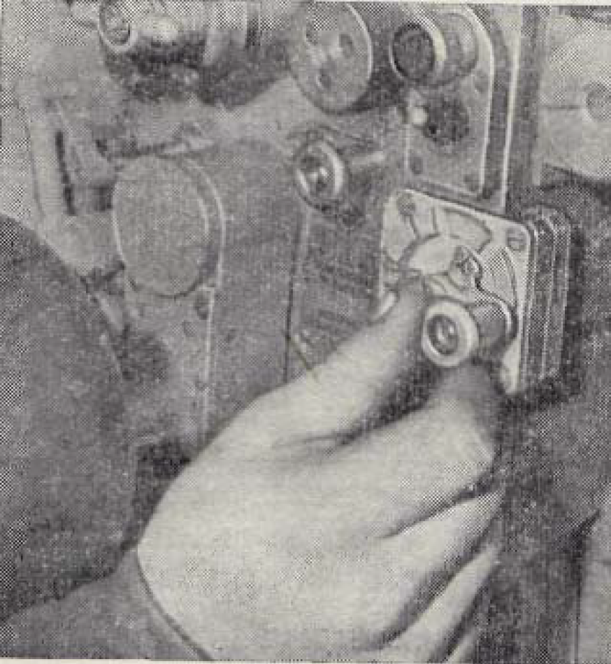
In case of an emergency due to a breakdown of the coincidence ranging mechanism, it was possible to use the sight as a stereoscopic rangefinder where right eyepiece displayed the full image (without a split viewfinder) from the secondary optic and the gunner could measure the range by turning the range adjustment wheel until the image of the target in both the primary and secondary eyepieces were exactly superimposed. This feature was made a requirement during the development process of the sight as a compromise between the proponents of stereoscopic and coincidence rangefinders. The provision of the stereoscopic rangefinding mode may be the reason for the omission of a stadia rangefinder scale as a backup ranging option.
The rangefinder has an automatic range compensation mechanism for firing on the move known as a Delta-D system. The system is intended to subtract the distance covered by the tank after a range input when the tank is in motion relative to the target. The angular position of the target relative to the tank is determined by a cosine potentiometer. The speed of the tank is measured by a tachometer installed on the axle of the right idler wheel. The accuracy of the measurement can be degraded by track slip, which will vary depending on the terrain. From these inputs, the system subtracts from the range setting in the sight by rolling back the range dial and raising the sight reticle. The gunner must manually re-adjust his aim as the reticle moves.

The technical manual for the TPD-2-49 sight states that the average range measurement error is 3% from 1,000 meters to 2,000 meters, 4% from 2,000 meters to 3,000 meters, and 5% from 3,000 meters to 4,000 meters. However, according to the document SW 82-10067 X titled "The Soviet T-72 Tank Performance" from the CIA, the rangefinding accuracy of the TPD-2-49 sight is actually slightly better than the Soviet figures suggest, although the figures in the table still align quite closely. It is possible that a difference exists due to slightly different measurement criteria.

This level of ranging precision was much higher than the M17 optical coincidence rangefinder of the M48 Patton. In page 121 of a British report WO 194-2946 with the title "A Technical Assessment of the T-55", data from actual testing showed that for a "Patton coincidence rangefinder", the mean error in ranging tank-shaped screens, broadside tanks, oblique tanks, head-on tanks and hull-down tanks at distances of 970 meters to 2,520 meters is 6.65%. At the same distances against similar targets, the ranging errors from the TPD-2-49 would be 3-4% or 2.5-3.5% depending on the source. This is just half of the M17 rangefinder.
Compared to the M17A1 rangefinder in the M60A1, however, the TPD-2-49 has significantly lower ranging precision. According to a Soviet study of a captured Israeli M60A1, the median range error from 500 meters to 2,000 meters is only 1%. At 2,000 meters, the error margin is 1.25%, from 2,000 meters to 3,000 meters, the margin is only 2%, and at ranges above 3,000 meters (up to 4,400 meters), it is only 3%. This is 2 percentage points lower than the TPD-2-49 across all distances. The difference can be explained by the longer base length of the M17A1 rangefinder of 2,006mm, and the slightly higher 10x magnification might also have a small positive effect. M17A1 also has the advantage of having a shorter minimum measuring distance as well as a longer maximum measuring distance of 500 meters and 4,400 meters respectively due to the larger range of traverse of its objective prisms.
Although an error of a few percent seems small, it can make a significant difference when combined with the natural dispersion characteristics of the ammunition fired from the tank gun. If APFSDS rounds are fired, a ranging error of 2.5% is not a serious drawback when considering that the maximum tank engagement distance expected in Europe was only around 1,800 m, not to mention that the use of hypersonic APFSDS ammunition meant that the error margin was practically insignificant at closer ranges such as at the Fulda Gap where the maximum tank combat range did not exceed 800 meters since the ballistic trajectory was so flat. The problem was much more pronounced with HEAT and HE-Frag ammunition, which were heavier, experienced more aerodynamic drag and were launched out of the barrel at much lower velocities than APFSDS rounds. With the increasing proliferation of long range ATGM systems mounted on jeeps, scout cars, IFVs and even light tanks, the ability to deliver accurate long-distance fire with HEAT and HE-Frag shells was not a trivial matter.
An inherent shortcoming of optical coincidence rangefinders in general is that the accuracy of the measurement is noticeably degraded when the target is obscured by camouflage or inclement weather. To obtain the maximum image contrast, optical filters may be applied by the gunner. The main advantage of the TPD-2-49 over contemporary optical rangefinder sights is that it is stabilized. As long as the main gun is laid on the target, the gunner can carry out the rangefinding process while the tank is in motion.
Moreover, the independent stabilization of the sight worked in conjunction with the two-axis gun stabilizer to generate better accuracy. Like the advanced TPS1 sighting complex of the T-10A and T-10B heavy tanks and unlike the simpler "Meteor" stabilizer for the T-62, the vertical stabilizer of the cannon is slaved to the vertical stabilizer of the TPD-2-49, meaning that the vertical motion of the cannon is directly slaved to the stabilizer for the sight. Deviations in the angular position of the gun from the sight are detected with a resolver, which passes a feedback signal to the stabilizer which corrects the elevation angle of the gun until feedback is no longer received. On top of this, a fire gating system was implemented. This allows the system to achieve a higher accuracy as the system will only permit the gun to fire when the elevation angle of the gun is aligned with the sighting line, which has a more precise stabilizer than the gun and reflects the true point of aim dictated by the gunner. The much larger range of elevation of the independently stabilized sight also allows the gunner to maintain constant visual contact with the target as the tank and even engage it while the tank moves across undulating terrain, as the system will automatically fire the cannon when it is in the proper elevation angle as long as the gunner holds down the trigger button.
This feature also allows the gunner to see a target from a turret-down position behind the crest of a hill or a specially prepared ditch, which can be useful in certain situations. The gunner can search for a target, acquire a ballistic solution, lay the reticle on the target and proceed to press and hold the trigger button. When the commander gives the order for the tank to move forward, the gun will eventually align with the point of aim of the sight as the tank crests the hill and the gun will automatically fire. This is the signal for the driver to immediately reverse the tank back into cover. This can reduce the time spent in a non-turret-down position, thus shortening the period of vulnerability.
When the stabilizer is turned off, the sight reverts to a dependent stabilization mode. The sighting line will raise and depress along with the gun via the parallelogram linkage.
TPD-2-49 placed the T-72 "Ural" on equal footing with the best NATO tanks at the time in terms of fire control sophistication, including the Leopard 1. Compared to the M60A1 and Chieftain, the T-72 fire control system was qualitatively superior by a large margin. As the optical coincidence rangefinder was integrated into the sight and the whole package was independently stabilized (which no other system could boast of at the time), the TPD-2-49 could be considered a rather advanced sighting complex, on par with the fire control system of the Leopard 1 and superior to the setup on the M60A1 which had a separate primary sight and M17A1 rangefinder. The commander of an M60A1 would search for a target through his M28C periscope with his seat raised by 4". When a target is spotted, the commander would have to lower his seat to the lowest position in order to conduct the rangefinding process through the eyepiece of the M17A1 and enter the range data, and only then would the gunner be able to use his primary sight to conduct final lay to engage the target. In a T-72, the gunner alone carried out the rangefinding process and the final lay with the TPD-2-49 sight, and the formation of the ballistic solution would be immediately presented in the viewfinder of his sight. This streamlined the entire process, so the reaction time of the tank between the moment of visual contact and the firing of the first shot was slashed accordingly.
However, as time went on, it became increasingly clear that optical rangefinders were no longer satisfactory, largely because it took a great deal of concentration from the gunner to operate, and in the case of the TPD-2-49, it was very expensive to manufacture an advanced independently stabilized sight with an integrated optical rangefinder. They were also relatively fragile despite extensive shockproofing and the use of anti-vibration bushings in the mounting points, mainly due to the immense transfer of energy involved when dealing with anti-tank weapons. Any misalignment as a result of shocks from tank shell impacts could cause some lens to be misaligned even slightly and that would be enough to put it out of commission for the duration of a battle, and this was a big problem with the T-72 (and indeed, every other tank with such a rangefinder) because an optical tube connecting the first aperture to the main sighting unit ran across the turret ceiling above the cannon breech block. A shell impacting the turret roof might bounce off and not penetrate the steeply sloped armour, but the strong shock of the impact and the shifting of the relatively soft and relatively thin cast steel roof could cause enough damage to the optical tube that it might no longer be usable. The thick rubber bushings on the optical tube can be seen in the photo below.

The location of the optical tube connecting the apertures of the two optics can be seen in the photos below (credit to t-72.de).

This, in addition to the issues mentioned above, meant that production of TPD-2-49 sighting complexes was summarily discontinued soon after the improved TPD-K1 sight was available and modernization programmes to refit T-72 "Ural"s with TPD-K1 laser rangefinding sights began after that. The TPD-2-49 continued to be installed on mass produced tanks until around 1977 and "Ural" turrets cast with the armoured protrusion for the aperture port of the coincidence rangefinder optic continued to be produced along side it. T-72 "Ural" tanks modernized with the TPD-K1 did not have the armoured protrusion removed, but the aperture port was blocked off and permanently welded shut. Some modernized T-72 "Ural" tanks had the armoured protrusion cut off the turret roof, such as the example in the two photos below. The weld seams for the armour blocks to seal off the gap in the roof from the missing armoured protrusion are visible.


The sight is mounted to the turret at two points: the front of the sight housing is bolted to a bracket on the turret cheek with two bolts, damped with thick rubber bushings, and the top of the sight housing is suspended from the turret roof. The suspension point is damped with a rubber gasket and has a coil spring vibration damper. The image below shows the roof suspension assembly.

The housing for the primary optic of the TPD-2-49 sight is armoured.

The thickness of the side, the top cover, the rear, and the front of the armoured housing is 30mm. Based on the thickness alone, the sight housing should have enough armour to guarantee protection from machine gun fire and airbursting artillery shells. A similar armoured housing was used on the T-72A and T-72B. However, due to the slope of the turret roof, the presence of a gap for the sight head creates a narrow weakened zone where there is minimal armour protection. This zone is highlighted in the drawing below. A projectile penetrating the sight head in this zone may potentially cause damage to the sight itself, which will require much more serious repairs. At best, the projectile may only penetrate into the 50mm anti-radiation lining for the turret roof directly behind the sight head. Of course, an anti-tank weapon with high penetration power will quite easily defeat the limited armour in this zone and potentially kill the gunner with a head wound, but due to the extremely short height of this weakened zone, there is a very low probability of hitting it. The most relevant threats for this particular weakened zone are armour-piercing bullets larger than the 12.7mm caliber.

The glass window of the sight aperture is protected by a layer of SET-5L ballistic glass (19mm thick) to protect the internal mirrors from bullets and shell splinters. The ballistic glass panel comes with an integral heating system to prevent fogging, and it is provided with a small external wiper to remove any debris or mud that might obstruct the gunner's vision. There is also a sheet steel hood over the sight housing window that shelters it rain and snow, or even mud thrown up during rough cross-country driving. The hood is shown below. Tank crews carry an extra sight head in internal stowage for quick field replacement. To replace a damaged sight head, the bolts on top of the armoured housing must be removed.

The glass windows of the sight housing and the housing of the rangefinder optic both feature aerosol and air jet cleaning systems. The sight housing window has both a high pressure aerosol cleaning system and a mechanical wiper that is manually actuated by the gunner via a small rod. The rangefinder optic window only has the aerosol cleaning system, lacking a wiper. The air bottle for this cleaning system is mounted to the autoloader carousel and is not connected to the pneumatic system of the tank, and is thus not automatically refilled by the air compressor. When depleted, it can be swapped with one of the two air bottles in the driver's compartment, which are refilled. The reservoir of cleaning fluid has a capacity of 2.2 liters.

The cleaning system has a bank of nozzles arrayed along the top of the window to blow away dirt and snow. The system sources its air from the tank's high pressure air bottles, which are also used for the driver's periscope cleaning system and for starting the engine.
T-72 "Ural-1", T-72A (Early)
TPD-K1


The TPD-K1 is a sighting system which consisted of the sight itself in addition to the internal electronic ballistic calculator and the sight-stabilizer interface, including the control handles which are integral to the sight. It was first installed as standard tank equipment in 1978 on the T-72 obr. 1978 (one of the models colloquially known under the "Ural-1" umbrella term) and was retrofitted on a large number of older "Ural" tanks as part of a modernization effort. The TPD-K1 was later carried over to the T-72A in 1979 and to the T-72B in 1985 in a modernized form. The TPD-K1 first appeared in a T-72 in early 1975 and ten tanks with the new sight rolled off the production line at the tail end of the same year.
Around the same time, the T-64B had already entered mass production in 1976 and featured a new and more advanced 1A33 fire control system along with a guided missile launching capability. The 1A33 paired with the "Kobra" missile system was tested in a single T-72 prototype in 1976-1977 but did not enter mass production. It is interesting to note that older models of the T-64A were later upgraded with the TPD-K1 only in 1981. The Object 172M-1-E3 export variant of the T-72 is equivalent to the "Ural-1" model. This model is known simply as the T-72M and features a TPD-K1 paired with the cast monolithic steel turret of the original "Ural". It was used in various Warsaw Pact nations and in East Germany, as seen in the photo below.

The TPD-K1 sight is a modification of the TPD-2-49 and shares many components. The sight has a fixed 8x magnification and a field of view of 9 degrees, like the TPD-2-49. TPD-K1 placed the T-72 at the same level as its American nemesis the M60A1, which also received its own AN/VVG-2 laser rangefinder unit in 1978 as part of the M60A3 upgrade. German Leopard 1 tanks did not receive their own laser rangefinders until the 1980's rolled around.
Without an optical coincidence rangefinder system installed, the optic tube that ran across the ceiling over the cannon breech block in the T-72 Ural is no longer present.

Being a modernization of the TPD-2-49 sighting complex, the 78% of the components of the TPD-K1 were unified with its predecessor. Features such as the Delta-D system were retained. The TPD-K1 is independently stabilized in the vertical plane and it has an internal gyroscope installed in the same location as the one in the TPD-2-49. The range of independent vertical elevation is from -15 to +25 degrees, and the vertical cannon stabilizer of the T-72 is slaved to the stabilizer of the TPD-K1 sight in the same way as discussed previously with the TPD-2-49. Like its predecessor, the sight is not stabilized in the horizontal plane. This has implications that we will explore later.

Being a modernization of the TPD-2-49 sighting complex, the 78% of the components of the TPD-K1 were unified with its predecessor. Features such as the Delta-D system were retained. The TPD-K1 is independently stabilized in the vertical plane and it has an internal gyroscope installed in the same location as the one in the TPD-2-49. The range of independent vertical elevation is from -15 to +25 degrees, and the vertical cannon stabilizer of the T-72 is slaved to the stabilizer of the TPD-K1 sight in the same way as discussed previously with the TPD-2-49. Like its predecessor, the sight is not stabilized in the horizontal plane. This has implications that we will explore later.
The accuracy of stabilization, defined as the maximum amplitude of oscillations of the line of sight, improved to 0.2 mils. Based on the accuracy of the 2E28M gun stabilizer being rated at a tank speed of 35 km/h on "medium" cross-country terrain, it is likely that this accuracy of stabilization was also rated at 35 km/h under the same terrain conditions. This enhanced the targeting and firing precision of the weapon system as well as the image quality available to the gunner when he is observing the battlefield from a moving tank. The image below shows the image resolution of a sight with a stabilization accuracy of 0.1, 0.2 and 0.3 mils when the observer is in motion. However, this is limited to showing the effect of the vibrational amplitude, which is what the accuracy of stabilization represents. The actual deterioration of image resolution with TPD-K1 may not directly correspond to the image below because vibrational frequency from the tank suspension also plays a large role.

With the Johnson Resolution Criteria scale shown in the images as a reference, it can be determined that a stabilization accuracy of 0.2 mils is sufficient for level 1 (detection), level 2 (classification) and level 3 (recognition) observation of vehicles. Identification of the vehicle may only be possible when a distinct silhouette is presented.

The stabilizer system for the sight is connected to the cannon for angular referencing and to provide stabilization for the sight when the independent stabilization system of the sight is not used. The parallelogram-type mechanical linkages that connect the sight (left side) to the cannon (right side) can be seen in the photo below. This allows the sight to determine the orientation of the cannon relative to a reference point generated by its internal gyroscope (with three degrees of freedom) so that the fire control system only permits the gun to fire when the point of aim of the gun is aligned with the point of aim of the sight. This system is known as a firing gate. If the two systems were not in alignment, a firing inhibitor would be activated. This generated a level of firing accuracy proportional to the precision of the independent stabilization system of the sight instead of the precision of the much coarser weapons stabilizer. Furthermore, it is important to note that the use of parallelogram linkages resulted in a much higher level of precision in angular measurement compared to simpler push rods, reportedly 10-12 times more precise.

According to the technical manual for the 2E28M stabilizer, the fire gating system requires the sight and gun to be aligned such that the divergence did not exceed ±0.5 mils, the same as the TPS1 sight with the "Uragan" stabilizer in a T-10A. Compared to more modern stabilizers, the fire gate of the TPD-K1 and the 2E28M stabilizer has rather large tolerances. For comparison, the later Cadillac Gage stabilizer of the M1 Abrams permitted firing only when the divergence did not exceed ±0.25 mils.

According to the technical manual for the 2E28M stabilizer, the fire gating system requires the sight and gun to be aligned such that the divergence did not exceed ±0.5 mils, the same as the TPS1 sight with the "Uragan" stabilizer in a T-10A. Compared to more modern stabilizers, the fire gate of the TPD-K1 and the 2E28M stabilizer has rather large tolerances. For comparison, the later Cadillac Gage stabilizer of the M1 Abrams permitted firing only when the divergence did not exceed ±0.25 mils.
Another advancement of the newer system, as present in the M1A2 Abrams, was the decreased divergence between the bore axis of the gun and the line of sight through the primary sight. In the T-72, equipped with a TPD-K1, the divergence is between 1.5' to 4.5', or 0.43-1.30 mils, whereas in the M1A2 Abrams it is only 0.75 mils.
The ballistic computer in the TPD-2-49 and the TPD-K1 was calibrated to the standard conditions corresponding to the nominal values in the firing table. These conditions are:
- Barrel in a new condition with no wear
- Propellant charge and ambient air temperature of 15°C;
- Air pressure of 750 mmHg
If the firing conditions differ from the normal ones given in the firing table, for which the sighting system is calibrated for at the factory, then the corresponding correction coefficient can be entered into the potentiometer of the ballistic computer. The correction coefficient is obtained using the two nomograms displayed on the side of the 125mm gun. The nomogram on the left calculates the correction coefficient with barrel wear and air temperature as variables. The nomogram on the right calculates the correction coefficient with air pressure and temperature as variables.
The altitude of the tank above sea level is determined by the tank commander by referring to his map. The other variables require data to be relayed to the commander, obtained either by a meteorological survey unit or by measurements with personal devices. With this, the tank commander finds the correction coefficients on both nomograms and sums them up arithmetically. He then informs the gunner of the total correction coefficient, who can then enter it into the sight via the ballistic correction dial. The dial is a potentiometer, acting as a voltage regulator to the reticle superelevation signal generated by the mechanical ballistic computer of the sight. Effectively, the potentiometer acts as a dynamic analogue computer that calculates the virtual density from air pressure and temperature and the loss of projectile velocity from increased air resistance from colder air combined with gas leakage due to barrel wear.


For example, using the nomogram on the left, an air temperature of -25°C and a barrel wear of 2.5mm corresponds to a correction of 3.4%. Using the nomogram on the right, an air temperature of -25°C and an pressure of 650 mmHg corresponds to a correction of -6.1%. Added together, the total correction coefficient is -2.7%. Positive corrections increase the required superelevation angle for a given ballistic solution, and vice versa. These corrections mainly affect the accuracy of HEAT and HE-Frag shells at long range, as they are much more sensitive to deviations from normal firing conditions.
The same system of manual data entry for ballistic corrections is used on the M60A3 and M1 Abrams, as described in the Master Gunner's Corner of the May-June 1982 issue of ARMOR magazine. The only exception is that instead of a nomogram, separate pressure and temperature readings are entered.
The armoured sight aperture housing on the turret roof is very similar to the one used on the TPD-2-49, but instead of a simple sheet steel hood, additional ballistic protected is afforded to the sight aperture by the presence of two armoured "ears". The armoured "ears" extend quite a long distance from the aperture itself and fulfill the same purpose as the armoured doors of modern sight housing designs. The TPD-2-49 lacks such doors, so the aperture is only protected by a layer of ballistic glass without the option to seal it with an armoured shield like the night vision sight on the tank. A sheet steel hood is bolted to the armoured "ears" to provide protection from the elements in the same way that the hood for the TPD-2-49 did, and to shield the sight window from air-dropped napalm. Beginning in 1984, the T-72A began to receive the "Nadboi" anti-radiation cladding on many of the external surfaces of the tank. The armoured housing of the sight also received a layer of "Nadboi" as did the sheet steel hood, as the photo below shows.

The thickness of the two armoured "ears" is 11mm and the thickness of the sheet steel hood is around 4mm, as shown in the photo below kindly supplied by Jarosław Wolski (measurement was done on a T-72M1). The same shroud from the TPD-2-49 housing to shelter the sight aperture from the elements. As you can see in the photo above (showing a T-72B), the armoured "ears" may help limit the damage done to the sight aperture if one of the Kontakt-1 explosive reactive armour boxes next to the sight housing are detonated. It is unclear if the hood is made from armour-grade steel or just simple mild steel.

The TPD-K1 alone is shown in the two photos below. Note the two distinct polarized halves of the sight aperture. The laser rangefinder emitter and receiver is installed in the right half (LHS in the photo) and the gunner's optical viewing channel is on the left half (RHS in the photo). Note that the TPD-K1 in the two photos below is being suspended from its top mounting point. The mounts for the TPD-K1 are the same as the TPD-2-49.


The TPD-K1 comes with an integral neodymium doped glass infrared laser rangefinder. The sight is slightly unusual in that the laser rangefinder is installed inside the sight itself on the right hand side of the housing, but the rangefinder computer is installed outside the sight. This is apparently due to the fact that the TPD-K1 is essentially a modified TPD-2-49 sight, so the laser computer is practically an add-on module. The range data is processed in the rangefinder computer as digital information, which is converted to an analogue signal before it is converted to mechanical gun superelevation information using the mechanical ballistic computer. The mechanical ballistic computer is the same as in the TPD-2-49. The rangefinder is activated by pressing the right thumb button on the gunner's control handles, while the left thumb button is used to dump the range data memory in the sight (reset sight to 0 distance). The rangefinder lases only once with each press of the rangefinder button, regardless of how long the button is held after it is initially pressed.
The two photos below show the detached rangefinder computer. It is a processing and readout unit, with a digital display on its control panel to indicate the range reading, rounded up to the nearest meter. When lasing a target, three laser pulses are emitted in quick succession. To process the range data, the laser rangefinder computer features the ability to filter out measurements by fixed range thresholds at the gunner's discretion.


The photo belows show the rangefinder computer attached to the right side of the TPD-K1 sight module. When fighting at night, it is possible to aim at targets using the night sight but lase the targets using the TPD-K1, and then manually read the range measurement on the digital display to apply a correction in the night sight. To use the range filter system of the rangefinder, there is a range filter toggle switch located at the bottom of the unit. It is used to filter out range measurements of less than 1,200 meters or 1,800 meters, and placing the toggle switch in the central position lets the system run normally. This is used suppress bad readings due to clutter or obstructions such as bushes and wooden fences. If the gunner suspects that the range data is incorrect based on his intuition or based on a quick measurement by the commander using his stadia rangefinder, then the gunner can either lase the target again or use the range filter to obtain a true reading.

According to the Indian Ordnance Factories website, the laser rangefinder uses an IR laser in the 1,060 nm wavelength.
The laser rangefinder has an RMS range error of 10 m at distances of 500 m to 3,000 m. This is equivalent to an error margin of 0.33%. From 3,000 m to 4,000 m, the RMS error is 15 m. The rangefinder may become unreliable at distances of more than 3,000 meters due to laser scattering, so it could be necessary for the gunner to manually dial in the range to the target by other methods. Combined with the natural dispersion of the ammunition, this limitation makes it infeasible to engage point targets at distances beyond 3,000 m, but firing HE-Frag shells at targets further than 3,000 m is not a serious issue.
The two photos below show a TPD-K1 with the mechanical linkages that connect the sight to the cannon. The photo on the right is partly dismantled, exposing the internal PCBs in the laser rangefinder computer. The large rear suspension point on the top of the sight housing is clearly visible in both photos, but the armoured cap is missing on the example in the photo on the right. The shock-damping bushing on the screw is visible in both photos.


The rangefinder computer has a digital display to show the measured distance, and range information is ported through to the range indicator dial on the top of the gunner's viewfinder, which is the main display method for the gunner, as he does not have to break visual contact with the target. However, reading the range is generally not necessary since the fire control system will automatically calculate a ballistic solution. To lase a target, the gunner must place the illuminated red circle over it and then press the lase button (the right thumb button on the control handles). Almost immediately, the digital readout on the rangefinder computer will display the range, and the electromechanical ballistic computer will begin to lower the reticle, producing the ballistic solution, while at the same time the range scale at the top spins to give a visual reference for the distance. A firing solution is generated within 1 to 3 seconds and the gunner can then proceed to lay the reticle on the target. If the target is mobile, it must be tracked within the boundaries of the red circle until the range is obtained. The rangefinder unit takes an average of 6 seconds to cool down between uses, but rapid lasing with an interval of 3 seconds is permitted for short periods.
Range information is automatically routed to the ballistic computer integral to the sight, and the sight adjusts the reticle accordingly via the ballistic cam corresponding to the setting on the ammunition selector dial. Aside from the electromechanical integration of the laser rangefinder, the TPD-K1 functions the same as the TPD-2-49 when engaging targets with the main gun.

The ranging procedure is quite normal in the realm of tank fire control systems, but one oversight is that the laser rangefinder is fixed to the sight housing and has its own aiming axis, rather than being merged into the same optical group for the visual system of the sight. The separation is on a structural level, with the sight head itself being divided into two halves, the right half for theemitter and receiver of the laser rangefinder, and the left half for the gunner's optical sight. This can be observed when boresighting, when the reticle is adjusted until coincidence is achieved with the point of aim of the gun bore, while the aim point of the laser rangefinder does not change. The reticle can be adjusted by ±9 mils horizontally and vertically for boresighting purposes.
In case the laser rangefinder breaks down or is incapable of returning an accurate range measurement for whatever reason, the TPD-K1 has a backup stadiametric rangefinder with markings for distances of 500 meters to 4,000 meters. Together with the manual
gun laying mechanisms, this allows the gunner to continue engaging targets even if all fire control systems have completely lost power. The image on the right below shows an example of a range measurement with the stadia scale on a tank at arange of 1,500 meters. A stadia rangefinder was not needed as a backup in the TPD-2-49 because the optical rangefinder had no reliance on electrical power.


The viewfinder markings can be illuminated by an internal lamp for cloudy weather or when fighting in low light conditions.
The reticle of the sight includes a ladder-type graduated scale for firing the PKT coaxial machine gun to a maximum range of 1,800 m, for firing HE-Frag shells to a maximum direct fire range of 5,000 m, and markings on either side of the center chevron for manually applying lead on moving targets or for wind deflection corrections. On the top of the viewfinder is the range indicator dial which displays the measured range to the target. The dial is limited to a maximum range of 4,000 m. Once the gunner has lased the target, the range will be displayed here for the gunner's reference.
Thanks to the use of digital data storage, it became possible to reset the range setting in the sight to zero at the press of the left thumb button on the gunner's control handles. With this feature, the range equivalence scale for the coaxial machine gun on the rotating range disc was removed, and the method for accurately engaging targets with the coaxial machine gun was somewhat simplified compared to the system used on the TPD-2-49. After measuring the range to the target, the gunner notes the range by either referring to the range disc or the digital display on the laser rangefinder computer, and then he resets the range to zero. Then, he uses the range ladder scale to lay onto target and fire. The advantage of this simplification is that the gunner does not have to use the range adjustment wheel to manually set the position of the reticle according to the machine gun range equivalence scale, or return it to the zero position. However, the downside is that if the gunner needs to keep the range setting in the sight for some reason, the machine gun would have to be aimed by observing the tracers. There are no markings for distances below 50 meters, so the gunner must aim entirely using tracers when engaging targets at very short ranges.


As mentioned before, target leading is done manually by using the markings on either side of the center chevron. The gunner must estimate the lateral speed of the target by determining how long it takes for the target to move from the center chevron across the lead markings, and combine that information with the time of flight of the selected ammunition type to the measured range. Needless to say, this was not easy unless the gunner was experienced, and even so, the accuracy of manual lead estimation is invariably lower than an automatically computed lead solution. However, the significance of this deficiency against moving tank-type targets is counteracted by the immense speed (~1,800 m/s) of the APFSDS rounds fired by the T-72. At short ranges, the acceptable margin of error for lead with APFSDS rounds is very large, so it is quite forgiving to less experienced or less well-trained gunners.
The inputted ammunition type is indicated by one of three coloured signal lamps at the top left corner of the sight. If the fire control system is being operated manually or in a degraded mode, the sight can be set to the desired ammunition type by turning the dial next to the signal lamps. Otherwise, the ammunition type is automatically inputted.
The ballistic computer in the sight is able to account for the ambient temperature, gun chamber or ammunition charge temperature, atmospheric pressure, and barrel wear. These values are calculated using a nomogram printed on the recoil guard on the commander's side and manually entered into the sight via a potentiometer dial on the upper right corner of the TPD-K1. Along with range data, this amounts to six variables. Due to the lack of sensor equipment to automatically detect environmental factors, this can only be done prior to a combat mission. It is not feasible to dynamically input corrections during combat.
As with the TPD-2-49, the TPD-K1 was also fitted with an aerosol periscope head window cleaner. The system differs in that the sight lacks a second optic port for the coincidence rangefinder, and as such, there is only one aerosol sprayer for the main sight.

T-72A, T-72B
1A40, 1A40-1 Sighting Complex


The TPD-K1 sight, originally considered a piecemeal sighting unit, was later reclassified as the primary sight of the 1A40 sighting complex. The 1A40 sighting complex consists of the TPD-K1 sight and either the TPN1-49 or TPN3-49 night sight. If the 1K13-49 sight with the 9K120 "Svir" missile control system is installed, the fire control system is designated as the 1A40-1. In conjunction with this reclassification, the TPD-K1 received some small improvements related to the fire control system, the most notable of which is the new add-on lead calculator. The laser rangefinder was also improved in some way to permit shorter cooldown periods between lasings. According to Mikhail Baryatinsky, the T-72A received the 1A40 beginning in 1982, and the 1A40-1 came standard on the T-72B since its formal introduction in 1985. The T-72B1, lacking an ATGM capability, was fitted with the 1A40. 1A40 or 1A40-1 systems fitted to T-72BA tanks differ by the implementation of additional ballistic corrections using data collected by an external wind sensor and by a cant sensor.
It is important to note that the reclassification of the sight from TPD-K1 to 1A40-1 was not trivial. With the implementation of the ATGM guidance system, special changes were needed in the behaviour of the stabilizer, and as the gunner's control handles are integral to the TPD-K1 sight, the sight itself received a new electrical socket to connect to the missile control box.

The 1A40 sighting complex includes an additional eyepiece for the gunner's left eye for the UVBU lead calculation system. UVBU stands for "lateral lead generation device". The UVBU is an add-on system that brings the capabilities of the fire control system to a more modern level. The electronic calculator of the UVBU system is a separate unit that interfaces with the stabilizer, the gunner's control handles, the fire gating system, and the Delta-D mechanism.

The 1A40 sighting complex includes an additional eyepiece for the gunner's left eye for the UVBU lead calculation system. UVBU stands for "lateral lead generation device". The UVBU is an add-on system that brings the capabilities of the fire control system to a more modern level. The electronic calculator of the UVBU system is a separate unit that interfaces with the stabilizer, the gunner's control handles, the fire gating system, and the Delta-D mechanism.
The primary function of the UVBU is to calculate the lead for a moving target based on the tracking rate of the turret, the selected ammunition type, meteorological corrections and barrel wear compensation entered manually by the gunner, and cant (roll angle). Cant calculation is only provided if the tank is stationary. The cant calculation functions up to a roll angle limit of 15 degrees.
The input for the angular tracking rate is the control signal from the gunner's control handles, not the rotation of the turret itself. As such, the target leading function of the UVBU system can be used while the tank is on the move, as it is unaffected by the counter-rotation of the stabilized turret from changes in the orientation of the hull.
If a meteorological sensor is fitted, the UVBU system also takes crosswind deflection into account in its lead calculation. When engaging a moving target, the UVBU system calculates the necessary amount of lead and displays it in figures which can be manually applied by the gunner on the lateral scale in the TPD-K1 sight viewfinder. For T-72BA tanks, when a stationary tank on a side slope lases a target, the required lateral correction to account for lead, cant and crosswind will be displayed. The indicator unit, shown below, is comprised of a clamp, the eyepiece, and the connector that is plugged into the TPD-K1.

The lead calculation system works by taking the tracking rate as the gunner is lasing the target, combining it with the ballistic data of the selected ammunition, and then translating that information into an angular deflection value in mils, which is displayed in the eyepiece as a virtual projection at infinity. The gunner will then know which marking on the lateral mil scale on the reticle he should adopt as the new aiming point. The system will display the mil figure as a positive or negative fraction to denote which the side that the gunner must use (negative for the scale on the left of the center chevron and vice versa). The display will remain in the indicator as long as the rangefinder button is held. The use of an eyepiece rather than a separate digital display ensures that the gunner does not need to break visual contact with the target. As the UVBU eyepiece displays a number on an empty background, the gunner can keep both eyes open while operating the sight to see the number floating in his vision, read the necessary deflection figure and then apply it.

The lead calculation system functions across the entire working range of the fire control system, from 500-4,000 meters. The limit of the displayed lateral correction is 31.5 mils in either direction, almost fully spanning the entire deflection scale, which is marked for 32 mils in either direction. The maximum angular speed of the moving target is 1 degree per second, which is equivalent to a crossing target moving at a speed of 32 km/h at a range of 500 meters, or a crossing target moving at 251 km/h at a range of 4,000 meters. Thus, the leading system technically permits the gunner to engage relatively low speed, low-flying aircraft such as helicopters. The precision of the UVBU unit is not particularly high compared to the systems employed in more advanced fire control systems as it can only display a difference in the angular velocity of the target compared to the tank in increments of 0.5 mils (0.53 milliradians or 1.8 minutes of angle). This is partly because the graduated lateral correction scale in the sight viewfinder is in increments of 1 mil, and the gunner can only be expected to use the midpoint between increments as the aiming point, so smaller divisions are not feasible. The low precision of this method of lateral compensation has a negative effects on the hit probability at long ranges. Moreover, the semi-automatic nature of the system means that human error (primarily in the chosen point of aim) contributes more to the total error. The system is generally inferior to the lead compensation mechanisms of contemporary fire control systems for long range shooting against moving targets, especially with lower velocity ammunition like HEAT and HE-Frag.
Other than that, the most serious drawback is the lack of automation. In the fire control system of an M60A3, for instance, lead for a moving target is calculated and automatically applied to the reticle by the ballistic computer after the target is lased, meaning that the reticle automatically adjusts horizontally so that the reticle has already compensated for lead. This allows the gunner of an M60A3 to press the trigger immediately after lasing as long as he continues to track the target with the reticle - no need to adjust the aiming point or use secondary markings to engage. This is faster than the system employed on the TPD-K1. This is an inherent flaw in the sight itself as it cannot automatically adjust the reticle for lead since it lacks independent horizontal stabilization and there is no provision for the horizontal displacement of the reticle in the viewfinder of the sight. While it may have been considered an innovative feature for a sighting complex from the late 1960's, the UVBU leading system was somewhat crude for 1982 and could already be considered technologically obsolete at the time that it was introduced. By the time the T-72B entered mass production in 1985, the 1A40-1 sighting complex itself could be considered outdated. The TPD-K1 is shown in the two photos below.


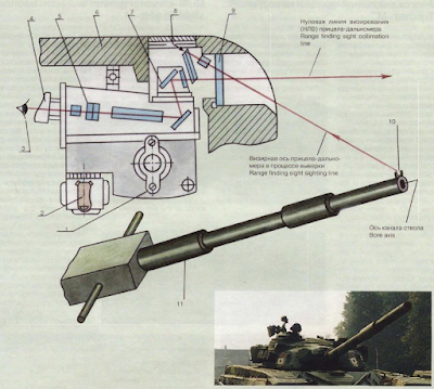
The updated TPD-K1 sight of the 1A40 or 1A40-1 system also differs from the basic TPD-K1 in the viewfinder. The main difference is the presence of mil values printed on the lateral correction chevrons for the gunner's reference in conjunction with the UVBU leading system. Otherwise, the viewfinder is essentially identical.


The photo below (credit to: ru-armor.livejournal) shows the markings more closely.

It is possible to use different shell models by simply twisting a dial on the UVP control unit, pictured below. Eleven distinct types can be selected from this unit. The UVP control unit was first used on the T-72B. It is installed under the linear acceleration sensor, mounted to the turret roof, in front of the commander (behind the TKN-3 if the cupola is facing forward).


The initial selection of ammunition models available in the UVP unit by default is:


Beginning in August 1989, the gun on T-72B tanks may be boresighted from inside the tank using the UVKV device, added to the 1A40 fire control system. The system requires that a 2A46M or 2A46M5 gun is installed. UVKV stands for "built alignment control device". It is a add-on device fitted to the armoured housing of the sight, just in front of the periscopic head of the TPD-K1 sight. It consists of an optical assembly containing a fixed lens group and a hinged, spring-loaded prism, with a pullcord to lower the prism over the aperture of the sight.
The focal distance of the objective lens is 5,600mm, which is the distance between the sight and the muzzle of the gun. The boresighting notch will therefore be in focus, while the barrel and background will be out of focus. The view through the UVKV lens is restricted to 4.25 degrees. The gunner will therefore see the same viewfinder markings, but a much narrower image than normal.

To carry out the boresighting process, the gun is elevated to a specific angle (ostensibly to maximum elevation), and then, the gunner lowers the UVKV unit over the aperture window of the sight by pulling on the pullcord. The view from the sight is thereby redirected through the lens of the UVKV unit via a prism so that the gunner will see the muzzle of the main gun rather than looking parallel to the axis of the gun. Using the TPD-K1, the gunner checks if the reticle markings are aligned with the notch. This is shown in the images below. If not, the sight is no longer correctly zeroed, and the gunner must calibrate the sight to the gun using the adjustment knobs.


The full process nominally requires 1 minute. The system is a static type, providing only a boresighting function. In practice, it can also be used to compensate for barrel bending, but because the process is not instantaneous, it may not be practical to do so in combat conditions. The maximum permissible alignment error is 0.15 mils. This may be higher than a conventional MRS that uses a mirror on the gun muzzle and light collimation. This visual boresighting method is fundamentally analogous to boresighting using an MRS (muzzle reference system), using special notches at the muzzle of the barrel which are used as reference points rather than collimated light. This feature is also integrated to the 1A40-1 and 1A40-1M sighting complexes.
The images below roughly illustrate the boresighting concept.


The updated TPD-K1 sight of the 1A40 or 1A40-1 system also differs from the basic TPD-K1 in the viewfinder. The main difference is the presence of mil values printed on the lateral correction chevrons for the gunner's reference in conjunction with the UVBU leading system. Otherwise, the viewfinder is essentially identical.


The photo below (credit to: ru-armor.livejournal) shows the markings more closely.

It is possible to use different shell models by simply twisting a dial on the UVP control unit, pictured below. Eleven distinct types can be selected from this unit. The UVP control unit was first used on the T-72B. It is installed under the linear acceleration sensor, mounted to the turret roof, in front of the commander (behind the TKN-3 if the cupola is facing forward).


- AP: BM9, BM12, BM15
- HEAT: BK12, BK18
- HE-Frag: OF19
Ammunition models other than this basic set are entered as additional entries.
The UVP unit allows the gunner to instantly reset the sights for different types of each category of ammunition. It is also possible for the T-72 to use "exotic" ammunition this way. For example, one of the blank spaces on the indicator card for HE-Frag (labelled OF in the photo above) can be filled for flechette rounds. The gunner can then toggle the sight for the HE-Frag ammunition type, and then cycle the HE-Frag dial on the UVP panel to the flechette slot.
NIGHT SIGHTS
An important tactical nuance of the sighting system is that the night sight and the day sight are almost completely independent systems. If the tank is denied its night fighting advantage by the enemy's use of illumination rounds to blind friendly forces, it is possible for the gunner to immediately switch to the day sight. Similarly, the commander can switch to the daylight mode on his TKN-3M by simply flipping a switch. This is a capability that was carried over from preceding tanks, and is shared with certain foreign counterparts such as the M60A1 series.
Other tanks, such as the Chieftain and Leopard 1, were not capable of switching between sights on the fly. The Leopard 1 permitted the commander to swap out his forward-facing periscope for an IR or passive night vision sight, but gave no sighting equipment for the gunner. The Chieftain allowed both the gunner and commander to swap out their day sights for an IR night vision sight, but according to historian and former Chieftain crewman Rob Griffin, this required a relatively lengthy boresighting and recalibration process, which would have to be repeated when swapping back the night sights for day sights. Needless to say, this is entirely unfeasible during combat.
T-72, T-72A (Early)
TPN-1-49-23
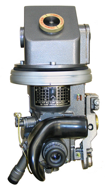

The TPN-1-49-23 is the gunner's night sight in the T-72 Ural and its variants, as well as almost all exported T-72 variants with the exception of the T-72S. It is a 1st generation night vision device that primarily relies on IR illumination, and has a secondary passive vision capability. The TPN-1 utilizes a single S-1 photocathode held at 18 kV.


The sight has a fixed magnification of 5.5x and a field of view of 6 degrees. For comparison, the night sight of the Chieftain had a 3x magnification and a field of view of 14.3 degrees. The TPN-1-49-23 can be used in the passive image intensification mode, relying on ambient light in the nevironment, or in the active infrared imaging mode, whereby infrared light emitted from the L-2AG "Luna-2" IR spotlight is used to illuminate the target. The "Luna-2" spotlight is mounted coaxially to the main gun so that all three devices - sights, cannon and spotlight - are adequately aligned. Like the commander's OU-3GA2 spotlight, the "Luna-2" spotlight uses an incandescent lamp with a IR filter fitted in front of the bulb. Removing the filter transforms the IR spotlight into a regular white light spotlight.
Unlike the L-2 spotlight on the T-54, T-55 and T-62 series, the spotlight on the T-72 was not installed on a raised bracket, being instead fitted well below the turret roof line. This was necessary because the commander was no longer seated on the same side of the turret as the gunner as on the preceding medium tank series, so it was no longer feasible to have the spotlight mounted at the same height as the night sight. Doing so would block the commander's forward vision, which would be completely unacceptable. It was of particular importance for the T-72 because the commander's TKN-3M periscope could depress by -8 degrees, more than what was possible in previous tanks. The only major implication of the new spotlight location is that the gunner cannot use the spotlight for illumination when scanning for targets in a turret defilade position with the TPN-1 sight peeking over cover, leaving only the commander with this capability. The image on the left below shows the bore axis offsets for all sights, spotlights and weapons on the turret relative to the main gun.


As the gain from Cold War era S-1 photocathodes exceeded those of WWII vintage, Gen 0 devices were not completely blind without active illumination, although they still depended heavily upon infrared spotlights to obtain a useful viewing range. The degree of light amplification was sufficient for passive observation only under moonlight illumination or greater.
Like the main sight, the TPN-1-49-23 is protected by a square-shaped armoured housing, with a bolt-on steel cover for the aperture. Beside the aperture is a single fixed FG-125 infrared or white light headlight, which is used only as a driving light and not for the TPN-1-49-23.

The sight has a maximum viewing distance of 500-800 meters in the active mode using the "Luna-2" IR spotlight. The range of 800 meters is referring only to the detection range on a tank silhouette target, either a front-on view or a profile view.
The maximum viewing distance of 800 meters is supported by the U.S Department of the Army Operator's Manual for the T-62, which notes on page 3-12 that the L-2G spotlight provides the gunner with ability to successfully engage targets at a range of 800 m. For comparison, the Chieftain had a maximum viewing range of 1,000 meters with its AFV No. 33 IR sight. This is likely due to its immensely powerful 2 kW spotlight with a large 570mm aperture, which should have greatly benefited the gunner in searching and engaging targets at longer ranges, compensating for the low 3x magnification of its sight.
The M60A1 used the advanced AN/VSS-1 spotlight, featuring a motorized lens and occluder that enabled the gunner to remotely adjust beam width from 0.5-0.75 degrees in the narrow mode to 7 degrees in the wide mode as well as select between white light and infrared light on the fly. The AN/VSS-1 ran on 1 kW and had an output of 75 million candelas in the white light mode, or 25 million candelas in IR mode. Additionally, the M32 IR night sight installed in the M60A1 had an 8x magnification, giving the gunner better long range visibility.
New passive night vision sight introduced in 1977 on the M60A1 Passive modernization offered better performance than the TPN-1 on the T-72, and towards the 1980's, large investments in thermal imaging technology in the U.S allowed them to completely leapfrog over the USSR in night fighting technology. This is best exemplified by the use of AN/VSG-2 thermal imaging sights in the M60A3 (TTS) in 1979. The T-72A was introduced in the same year, but most still had the same TPN-1-49-23 night sight, and only upgraded to the TPN-3-49 after some time into its production run, and only in small numbers.
Besides the general vulnerabilities associated with active infrared imaging systems, some countermeasures existed and were implemented on serial tanks, although these had rather limited success. One example is the infrared detector stalks used on Chieftain tanks, which was of extremely dubious utility. In the words of Rob Griffin on page 71 of his book "Chieftain Main Battle Tank: Development And Active Service From Prototype To Mk.11 (Part 2)" - In theory it was an excellent idea but in practice it was a dismal failure. False positives from ambient light were extremely frequent and as such, most troops would dismount the stalk and either leave it in a tool bin or back in the troop stores at the barracks unless the night combat exercise specifically focused on training crews in the use of the infrared detection equipment. It would be mounted on the tank for photo shoots and demonstrations to dignitaries and officials, of course.
Due to the short range of vision, the markings in the viewfinder of the TPN-1-49-23 are greatly simplified. All four ammunition types (including the coaxial machine gun) were represented on the markings, albeit not with complete exactness, but it was acceptable due to the short aiming distances expected. It's worth noting that the flat trajectory of subcaliber rounds like 3BM9 and 3BM15 made it infeasible to include them in the same set of markings as the other ammunition types, but their high muzzle velocity meant that it was fairly easy to hit a tank-sized target at short range anyway.

The end point of each line is an indicator for a certain distance for certain types of ammunition. A breakdown of the markings can be seen in the diagram below. This diagram is printed on an instruction panel on the sight itself, in case the gunner forgets the meaning of the markings in the heat of battle. As you can see in the diagram, the topmost point represents 100 meters for HE-Frag rounds, 200 meters for HEAT rounds and the coaxial machine gun, and 1,100 meters for subcaliber rounds. To fire subcaliber rounds at targets below 1,100 meters, the gunner would have to aim slightly above the topmost point. In practice, the topmost point serves as a battlesight mark, allowing the gunner to aim at the center of mass or the lower edge of a tank-sized target with a high probability of a hit at any range from 0 to 1,100 meters due to the flat trajectory of the shot.

It has been frequently noted in various websites that the T-72 can be distinguished from the T-64 by the change in position of the spotlight from the left side of the cannon to the right side. This change was not arbitrary; the spotlight was placed next to the coaxial machine gun port so that the driver was physically blocked from sticking his head out of the hatch and in front of the machine gun when driving the tank during road marches, and so that the driver does not have to be in front of the machine gun when entering and exiting his station.

The sight cannot be used in daytime, because sunlight will overload the sight unit and damage it, leading to premature failure. In accordance with this rule, the aperture has internal shutters linked to the firing trigger of the gunner's control handle. Upon firing, the shutters automatically close to shield the unit from the intense flash of cannon fire at night.
T-72A, T-72B1
TPN-3-49

Officially, the T-72A obr. 1979 and all T-72B1 models were equipped with the TPN-3-49 night sight. The TPN-3-49 was used as a substitute for the 1K13-49 in the case of the T-72B1, and it exists as an upgrade over the TPN-1-49-23 for the T-72A. However, many T-72As and a few T-72B1 tanks still had the TPN-1-49-23 installed during the 1980's, presumably due to issues with the availability of the TPN-3-49. By that time, many of the tanks of the opposing forces were already equipped with thermal imaging sights, so attempting to use T-72 tanks stuck with the outdated TPN-1-49-23 in night combat against armoured units would probably be tantamount to suicide. Even infantry weapons like the TOW and Dragon had begun receiving the AN/TAS-4 and AN/TAS-5 thermal imaging sights respectively by 1978. In this context, the longer viewing range of the TPN-3-49 was not nearly enough for T-72 tanks to even approach parity in night fighting capabilities with the probable enemy.
Like the TPN-1-49-23, the TPN-3-49 was mechanically linked to the main gun through a shaft passing through the TPD-K1 sight. The head mirror was thus vertically stabilized by the gun. The range of elevation of the sight was -6°13' degrees to +14°.

The TPN-3-49 sight has a magnification of 5.5x and a field of view of 6°40'. TPN-3-49 is essentially a TPN-1 with a new photocathode. Structurally, the sight retained many of the key features and drawbacks of its predecessor, including a lack of independent stabilization. One of the improvements of the TPN-3-49 over the TPN-1-49-23 is the ability to switch between different viewfinder markings for different ammunition types, giving the gunner better aiming precision.

Instead of a single universal set of markings with predetermined aiming points, the TPN-3-49 features comprehensive range scales and a range dial for each type of ammunition.
The new night sight features a more sensitive electron-optical converter tube and amplifier system, giving the gunner a brighter and clearer image of higher resolution when using the sight in the active night vision mode. Another improvement came from the installation of the newer L-4A "Luna-4" spotlight, which is considerably more powerful than the older L-2AG "Luna-2" spotlight. The L-4 series uses a xenon arc lamp which is much brighter than the incandescent lamp of the L-2 series. The image intensifier in the TPN-3-49 is improved, but still belongs to the 1st Generation so the maximum viewing distance (identification of a tank) is only around 500-800 meters at an ambient light level of 0.005 to 0.01 lux. This is comparable to tthe M60A1 RISE Passive with the M32E1 passive sight, which allowed tanks to be identified from a distance of not less than 500 meters without illumination as stated in the report "M60A1, M60AI RISE, and M60A1 RISE (Passive) Series Tanks, Combat, Full-Tracked 105-MM Gun - Update System Assessment".
The L-4A spotlight can be distinguished from the L-2AG by the location of the power supply cable socket. The socket on the L-2AG was located on the right side of the spotlight, but the socket on the L-4A is located at the back, as you can see in the photo on the right. The photo on the left shows an L-2AG.


Even without delving into thermal imaging technology, the night fighting capabilities of the T-72A were still rather limited. In terms of active infrared imaging, the T-72 was behind both the M60A1 and the Chieftain.
The L-4A "Luna-4" spotlight is underwhelming in comparison to the AN/VSS-1, seeing as the spotlight ran on just 600 W and had an IR output of 30 million candelas - between three to five times less than the AN/VSS-1. Additionally, the beam width from "Luna" was fixed at around 1 degree horizontally and 0.8 degrees vertically, making it exceptionally difficult to search for targets across open terrain. Furthermore, the lack of an occluder, otherwise known as a blackout shield, in front of the xenon arc lamp in "Luna-4" meant that only a part of the light was directed from the concave reflector. The rest of the light was emitted in a forward arc, illuminating the tank itself as well as the ground in front of it, making the T-72 an extremely prominent target once the spotlight was activated.

Despite these drawbacks, the TPN-3-49 apparently allows a T-72A gunner to spot a target at a maximum range of 1,300 meters in the active infrared imaging mode. This is surprising when we consider the fact that the reported viewing distance for the gunner of a Chieftain Mark. 3 is only 1,000 meters, although that might be due to the relatively low 3x magnification of the Chieftain's No. 33 IR night sight.
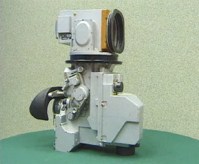
The 1K13-49 sight was created as the guidance control unit for the new 9K120 "Svir" laser-guided gun-launched missile system but continued fulfilling the function of a night vision sight, having improved night vision capabilities using technologies derived from the TPN-3-49. In 1984, a batch of 50 T-72A tanks were fitted with the sight and missile guidance system for troop trials. Within this batch, some were T-72AV tanks with the "Kvartz" turret and Kontakt-1 ERA, and some were T-72A tanks with an improved turret containing bulging plates (Object 184).

Despite these drawbacks, the TPN-3-49 apparently allows a T-72A gunner to spot a target at a maximum range of 1,300 meters in the active infrared imaging mode. This is surprising when we consider the fact that the reported viewing distance for the gunner of a Chieftain Mark. 3 is only 1,000 meters, although that might be due to the relatively low 3x magnification of the Chieftain's No. 33 IR night sight.
T-72B
1K13-49

The 1K13-49 sight was created as the guidance control unit for the new 9K120 "Svir" laser-guided gun-launched missile system but continued fulfilling the function of a night vision sight, having improved night vision capabilities using technologies derived from the TPN-3-49. In 1984, a batch of 50 T-72A tanks were fitted with the sight and missile guidance system for troop trials. Within this batch, some were T-72AV tanks with the "Kvartz" turret and Kontakt-1 ERA, and some were T-72A tanks with an improved turret containing bulging plates (Object 184).


The electronic modulator and signal generator for the missile guidance system is in separate boxes located on other parts of the tank, but the laser emitter is installed inside the 1K13-49 sight itself. The system has an operating range of 100 m to 4,000 m. The 1K13-49 has the same functions as the 1G46 sighting complex and shares the same missile guidance technologies, but the 1K13-49 sight has lower magnification and has a reduced maximum range compared to the 5,000-meter range of the "Refleks" missile system used on the T-80U and later, the T-90. The first tanks that were assembled with the "Svir" missile system appeared in 1984 but the system only entered mass production in 1985 as an integral part of the T-72B tank. It was absent on the T-72B1 variant. The location of the "Svir" system components are shown in the drawing below.

The sight has a daytime channel that is normally used in conjunction with guided missiles, but having a daytime channel allows the 1K13-49 to be be used as a backup sight in case the TPD-K1 is non-functional. With a fixed 8x magnification in the daytime channel, the 1K13-49 can be an adequate replacement for the TPD-K1. According to the manual, the detection and identification range of static and moving targets with the 1K13-49 in the daytime channel is 5,000 meters. The relationship between the magnification power of an optical sight and the viewing distance has already been explored before, but it is worth repeating that a sight with an 8x magnification allows a tank-type target to be seen and identified from 4.0-5.0 kilometers. Based on this, it is obvious that an 8x magnification was not arbitrarily chosen. Rather, it was necessary to allow 9M119 guided missiles to be used effectively at their maximum range of 4.0 kilometers.

If the 1K13-49 sight is used as a backup to the TPD-K1, its drawbacks include a reduced field of view, the lack of a laser rangefinder and no proper range scales for different ammunition types. The gunner is forced to make the most of the simplified markings provided in the viewfinder, shown in the drawings below. An unusual feature of the sight is that the aiming mark is offset to the right of the viewfinder.

The active infrared optoelectronic imaging system in the 1K13 sight is improved over the TPN-1 sight and is equivalent to the TPN-3. The target detection and identification range in the active mode with illumination from the L-4A spotlight is increased to 1,200 m. The passive mode has the same capabilities as the TPN-3, meaning that the 1K13-49 sight still only has an 500-800 m viewing distance under ambient lighting conditions of 0.005-0.01 lux. Like the TPN-1 night vision sight, the optical magnification power remains at 5.5x as this was still more than enough for the short viewing distances provided by the sight.
Like the TPN-3, comprehensive markings are provided for three ammunition types in the viewfinder of the night vision channel. The chevron and range indicator lines are adjusted up and down while the range scale remains static. To adjust for longer distances, the range indicator line is adjusted down until it lines up with the desired range, and the chevron will also drop down by the same amount. By laying the chevron onto the target, the gun is elevated by the necessary superelevation and the gunner can open fire.

The sight has a field of view of 5 degrees in the daylight setting or 6°4' in the nighttime setting. It is independently stabilized in the vertical plane, with +20° elevation -7° depression.

As usual, the sight aperture has two protective housings; one enclosing the sensitive optical workings of the aperture itself with a glass window and a shock-proof shell, and another very heavy duty steel carapace covering that, along with a thick steel window shield.


Externally, the key differences between the 1K13-49 and the other night sights lie in its distinctly larger armoured housing, complete with a remotely opened armoured shield.


Sosna-U is a multi-channel sighting complex with a thermal imaging system utilizing the French-designed Catherine-FC produced under licence by VOMZ (Vologda Optical and Mechanical Plant) since 2010. It has a television channel for the thermal imaging system and a daylight optical channel. Additionally, it has an integrated laser rangefinder and a laser emitter for guided missiles. The thermal imaging camera is installed on the sight as a separate module, with all other sight components retaining the capability to function independently of the camera. The sight has independent two-plane stabilization. If configured to perform as the primary sight in lieu of the TPD-K1, as on T-72B3 tanks, a modified or entirely new stabilizer is needed to ensure that it is slaved to the sight in both planes.

The sight has a daytime channel that is normally used in conjunction with guided missiles, but having a daytime channel allows the 1K13-49 to be be used as a backup sight in case the TPD-K1 is non-functional. With a fixed 8x magnification in the daytime channel, the 1K13-49 can be an adequate replacement for the TPD-K1. According to the manual, the detection and identification range of static and moving targets with the 1K13-49 in the daytime channel is 5,000 meters. The relationship between the magnification power of an optical sight and the viewing distance has already been explored before, but it is worth repeating that a sight with an 8x magnification allows a tank-type target to be seen and identified from 4.0-5.0 kilometers. Based on this, it is obvious that an 8x magnification was not arbitrarily chosen. Rather, it was necessary to allow 9M119 guided missiles to be used effectively at their maximum range of 4.0 kilometers.

If the 1K13-49 sight is used as a backup to the TPD-K1, its drawbacks include a reduced field of view, the lack of a laser rangefinder and no proper range scales for different ammunition types. The gunner is forced to make the most of the simplified markings provided in the viewfinder, shown in the drawings below. An unusual feature of the sight is that the aiming mark is offset to the right of the viewfinder.

The active infrared optoelectronic imaging system in the 1K13 sight is improved over the TPN-1 sight and is equivalent to the TPN-3. The target detection and identification range in the active mode with illumination from the L-4A spotlight is increased to 1,200 m. The passive mode has the same capabilities as the TPN-3, meaning that the 1K13-49 sight still only has an 500-800 m viewing distance under ambient lighting conditions of 0.005-0.01 lux. Like the TPN-1 night vision sight, the optical magnification power remains at 5.5x as this was still more than enough for the short viewing distances provided by the sight.
Like the TPN-3, comprehensive markings are provided for three ammunition types in the viewfinder of the night vision channel. The chevron and range indicator lines are adjusted up and down while the range scale remains static. To adjust for longer distances, the range indicator line is adjusted down until it lines up with the desired range, and the chevron will also drop down by the same amount. By laying the chevron onto the target, the gun is elevated by the necessary superelevation and the gunner can open fire.

The sight has a field of view of 5 degrees in the daylight setting or 6°4' in the nighttime setting. It is independently stabilized in the vertical plane, with +20° elevation -7° depression.
As usual, the sight aperture has two protective housings; one enclosing the sensitive optical workings of the aperture itself with a glass window and a shock-proof shell, and another very heavy duty steel carapace covering that, along with a thick steel window shield.


Externally, the key differences between the 1K13-49 and the other night sights lie in its distinctly larger armoured housing, complete with a remotely opened armoured shield.
1A40-4 Sighting Complex

The 1A40-4 sighting complex is integrated with the autoloader and stabilizer of the T-72B3 tank. The complex includes includes the Sosna-U sight, TPD-K1 sight, a digital ballistic computer, and a wide variety of sensors for ballistic data. The control handles for the stabilizer and the autoloader control panel are integrated to the TPD-K1 sight housing.
Sosna-U

Sosna-U is a multi-channel sighting complex with a thermal imaging system utilizing the French-designed Catherine-FC produced under licence by VOMZ (Vologda Optical and Mechanical Plant) since 2010. It has a television channel for the thermal imaging system and a daylight optical channel. Additionally, it has an integrated laser rangefinder and a laser emitter for guided missiles. The thermal imaging camera is installed on the sight as a separate module, with all other sight components retaining the capability to function independently of the camera. The sight has independent two-plane stabilization. If configured to perform as the primary sight in lieu of the TPD-K1, as on T-72B3 tanks, a modified or entirely new stabilizer is needed to ensure that it is slaved to the sight in both planes.
The design of the sight is compact enough that it can be fitted in the same position as the TPN-3 or 1K13 sight without modifications to the turret interior. However, the new sight head and its armoured housing are much larger, thus requiring the hole in the turret roof be enlarged to fit them.
Integrated control panels above and below the sight eyepiece provide the essential controls for operating the sight.

The right side of the sight housing contains the daylight sighting channel, the missile guidance beam emitter, and the laser rangefinder and all the necessary electrical system to support the operation of the sight.
Like the earlier sights replaced by Sosna-U, it is suspended from the turret ceiling by the sight head mounting collar, which is affixed to the turret roof on a rubber bushing to isolate the sight from powerful impacts on the turret.
The Catherine-FC camera is mounted next to the daylight sight with the camera lens encased by the protective die-cast aluminium housing. The rest of the camera itself is already sealed within its own aluminium casing with internal shock dampeners.
Behind the Catherine-FC camera is the laser encoding and modulating unit for the control of laser-beam riding missiles. The Sosna-U may have two different types of these laser control units, with no apparent difference in the name of the product.


The window for the thermal camera on the sight head is not made from glass, which is opaque to most of the infrared spectrum, but from germanium.
In the daylight mode, the sight provides a view through an optical channel for visible light (480-660 nm) which is accessed by the eyepiece on the sight housing. A tinted filter can be applied by turning a switch. For target scanning and precision shooting purposes, the gunner can switch between discrete low and high magnification settings. In the 4x magnification setting, the field of view is not less than 12 degrees. In the 12x magnification setting, the field of view is not less than 4 degrees.
In the thermal imaging mode, the sight produces a digital image constructed by its optical thermographic scanning system. The camera scans in the 8-12 nm range of wavelengths which is within the LWIR (long wave infrared) spectrum. The gunner and commander can only utilize the thermal imaging channel via an external flatscreen display connected to the sight. There are low and high magnification settings. In the 3x optical magnification setting, the field of view is 9 x 6.75 degrees. In the 6x optical magnification setting, the field of view is 3 x 2.25 degrees. When digital magnification is used, the image is magnified to a maximum factor of 12x, with a field of view of 1.5 х 1.12.
The thermal imaging system produces a high definition video output (625p) at a refresh rate of 50 Hz, with an image resolution of 754 x 576 px.

The two images below show the viewfinder of the sight in the daylight channel switched to the low magnification setting. The field of view through the high magnification setting is bracketed by four sets of marks in the four cardinal directions, so that the gunner may ensure that the visual contact with a target is not lost when he switches to the high magnification setting.


The two images below show the view in the thermal imaging channel.


Sosna-U also includes a target tracking system, demonstrated in this video. As with practically all object tracking algorithms in use, the tracking system relies on the bounding box approach. The bounding box is set by laying the viewfinder reticle onto the target and pressing the button, whereupon the target is identified by image contrast.

The 640 x 480 px (5.7 inch) multi-functional display (MFD) has three buttons for limited image display adjustments. The gunner can change the magnification settings with the "+" and "-" buttons, or switch between white-hot and black-hot display modes with the third button.


In addition to the sight itself, the T-72B3 upgrade also comes with a new digital ballistic computer. The sight itself cannot accept data from peripherals such as anemometers, thermometers, muzzle reference sensors, and so on. In order to make use of such data, a ballistic computer is necessary.
The addition of the flatscreen display and the digital ballistic computer eliminates the possibility of stowing ammunition in the turret on the wall behind the gunner, as the gunner's master control panel is now moved to a spot behind his left shoulder, and the ballistic computer housing occupies quite a lot of space behind his seat.
The sensor suite includes a meteorological mast constructed by combining a standard DVE-BS anemometer with an air temperature sensor. This is supplemented by an atmospheric pressure sensor installed inside the fighting compartment, on the autoloader carousel cover. There is also a thermometer on the carousel cover to measure the temperature of the propellant charges. A roll sensor was also installed.
An unusual drawback of the Sosna-U is that the sight head cover has to be manually opened by unbolting it, which seems to be a step backwards from the 1K13-49.


The IR lamp mounted next to the sight is used to replace the normal driving headlights if they are submerged under water or plastered with mud, which could happen if the tank is fording a stream or driving through a swamp. This lamp is turned on and off by the commander.
TPD-K1
The TPD-K1 sight is retained as a backup to the Sosna-U. It is reduced to a standalone module as it was in the earliest versions of the T-72 - it is not connected to the ballistic computer and does not apply corrections based on sensor data.
STABILIZERS
At the time the T-72 entered service, a gun stabilizer had been a standard feature of all tanks in the Soviet Army for almost two decades, and foreign tanks such as the M60A1 and Leopard 1 were also beginning to receive add-on stabilizers. In this context, the firepower advantage of the T-72 mainly manifested in the use of a more sohisticated stabilizer control system where the gun was slaved to the sight rather than the simple gun stabilizers used abroad.
Turning on the stabilizer is done with the central toggle switch located just above the control handles on the TPD-K1 sight. The control handles integrated on the sight slightly differ depending on the stabilizer installed in the tank, but all share the same design.
Unlike the handles for the fire control systems of previous Soviet tanks, the handles are permanently attached to the TPD-K1 sight as an integral device. Potentiometers generate a signal from the vertical and horizontal deflection of the handles which are translated into the movement of the gun and turret via the stabilization system. The handles have a protruding ledge at the base for the gunner's hands to rest on, and the handles have two buttons each. The left trigger button is for firing the coaxial machine gun and the left thumb button is resetting the range in the sight (range memory dump). The right trigger button is for firing the main gun, and the right thumb button is for firing off the laser rangefinder. The firing circuit prevents the machine gun and main gun from firing at the same time.

The 2E28M dual-axis stabilizer is used in the T-72 Ural. Both the turret traverse and gun elevation drives are hydraulically powered. The stabilizer has two modes of operation: automatic and semi-automatic. The automatic mode is the primary mode for combat purposes; the stabilizer is at full operational capacity and will continuously attempt to align the gun with the aiming point of the gunner's primary sight with maximum precision. This mode is the default mode during combat and is used when firing from all positions - stationary, while moving, and during short halts. The semi-automatic mode is an auxiliary operating mode as well as an emergency mode in the event of stabilizer failure. In this mode, the elevation of the sight becomes directly slaved to the gun and the level of precision is reduced accordingly. The turret rotation speed is also slightly increased as the elevation mechanism no longer draws power. The semi-automatic mode is most suitable when the tank is stationary, or for firing during short halts, but it is not ideal for combat because the autoloader is consequently automatically set to the semi-automatic mode. Without the powered gun elevation system, the autoloader system cannot control the gun elevation angle to load rounds into the chamber, hence reverting to its semi-automatic mode. The slightly increased maximum turret traverse rate in the semi-automatic mode may help for tracking moving targets when the tank is in a stationary defensive position, but to fire upon targets, the automatic mode should be used.
Unlike the handles for the fire control systems of previous Soviet tanks, the handles are permanently attached to the TPD-K1 sight as an integral device. Potentiometers generate a signal from the vertical and horizontal deflection of the handles which are translated into the movement of the gun and turret via the stabilization system. The handles have a protruding ledge at the base for the gunner's hands to rest on, and the handles have two buttons each. The left trigger button is for firing the coaxial machine gun and the left thumb button is resetting the range in the sight (range memory dump). The right trigger button is for firing the main gun, and the right thumb button is for firing off the laser rangefinder. The firing circuit prevents the machine gun and main gun from firing at the same time.
2E28M "Siren" ("Lilac") Hydromechanical Stabilizer
The 2E28M dual-axis stabilizer is used in the T-72 Ural. Both the turret traverse and gun elevation drives are hydraulically powered. The stabilizer has two modes of operation: automatic and semi-automatic. The automatic mode is the primary mode for combat purposes; the stabilizer is at full operational capacity and will continuously attempt to align the gun with the aiming point of the gunner's primary sight with maximum precision. This mode is the default mode during combat and is used when firing from all positions - stationary, while moving, and during short halts. The semi-automatic mode is an auxiliary operating mode as well as an emergency mode in the event of stabilizer failure. In this mode, the elevation of the sight becomes directly slaved to the gun and the level of precision is reduced accordingly. The turret rotation speed is also slightly increased as the elevation mechanism no longer draws power. The semi-automatic mode is most suitable when the tank is stationary, or for firing during short halts, but it is not ideal for combat because the autoloader is consequently automatically set to the semi-automatic mode. Without the powered gun elevation system, the autoloader system cannot control the gun elevation angle to load rounds into the chamber, hence reverting to its semi-automatic mode. The slightly increased maximum turret traverse rate in the semi-automatic mode may help for tracking moving targets when the tank is in a stationary defensive position, but to fire upon targets, the automatic mode should be used.
Normally, the stabilizer is turned off entirely when combat is not expected, and the time needed to get the stabilizer to operational condition is two minutes. The stabilizer can remain in continuous use (turret traversing, braking, compensating for vibrations, gun moving) for a maximum period of four hours. Having the stabilizer in use for more than four hours can result in premature wear due to thermal stress in the amplifier and pump motors. Without continuous use, the stabilizer can remain turned on for as long as needed under normal conditions, including in dusty environments and while the tank is on the move.
Unlike the T-62, T-55 and T-54 series where turret rotation was actuated by an electric motor mounted on the turret ring, a hydraulic turret rotation motor was needed to cope with the high load of the unbalanced turret, especially if the tank was on an incline or a side slope. With the use of a hydraulic motor, an additional fire risk was introduced, because if the turret or turret ring was penetrated, the possibility of an explosion of aerosolized hydraulic fluid arose.
To remedy this issue, the hydraulic turret rotation drive was located in the hull, behind the port side fuel tanks, and the hydraulic gun elevation booster was suspended under the 125mm gun alongside the gyro block. Only the replenisher fluid container (20) for the gun elevation drive is in the turret, behind the turret cheek armour. As such, there are no pressurized hydraulic fluids circulating in the turret exposed to a direct hit in case the turret is penetrated during combat. The diagram below, representing a T-72 turret with the original 2E28M stabilizer, shows the layout of all components linked to the stabilizer system. The components containing pressurized hydraulic fluid are the hydraulic booster for the gun elevation drive (2), the hydraulic turret rotation motor (13) and booster (11).

The photo below shows the turret rotation drive. To make use of the remaining space between the autoloader carousel and the battery rack, two rounds of ammunition are stowed next to the turret traverse drive.

As with any other 2-plane stabilizer system, the 2E28M revolves around the use of a pair of gyrostabilizers, housed inside a gyro block, for measuring angular velocities in order to enforce corrections. The "L"-shaped hydraulic booster and the gyro block fit together into a rectangular package that is suspended under the 125mm gun.


The screenshot below (screenshot taken from this video) shows the location of this gyro block and hydraulic booster pair. It is well below the turret ring. When the gun is fully elevated, these components fit into the empty space in the middle of the autoloader carousel.

Gun elevation is actuated by a hydraulic piston anchored to the left side of the gun breech on one end and to the turret roof on the other end. When directed with the control handles, the actuator is capable of smooth gun control at a speed of at least 3.5 degrees per second, but when the tank is in motion over uneven terrain, the gun is elevated and depressed at a speed of up to 8.5 degrees per second to counteract the pitching rate of the hull, in order to maintain a stable point of aim.
If, during high-speed tank motion on uneven ground, the gun descends at a speed of 7.0-8.5 degrees per second or more, the elevation drive automatically brakes by hydrolock to prevent the gun from slamming into the ground. This is a necessary safety measure for travelling at high speeds on rough terrain, as the barrel of the 125mm is very long, and its overhang is quite pronounced due to the low height of the tank.


As mentioned earlier, the hydraulic motor for turret traverse is installed on the wall of the hull in a niche behind the front left fuel tank, which meant that the turret ring design differed considerably from other tanks. Instead of a fixed toothed ring affixed to the hull that the traverse gear pushes against, the hydraulic motor drives the turret via a toothed ring attached to the turret. Additionally, the T-72 turret ring still has a fixed toothed ring for the manual traverse mechanism.

The hydraulic motor provides two traversing modes: precise aiming and high speed. The precise aiming mode is controlled by the gunner's control handles and is used to set the point of aim on a target, to track moving targets, and to fire upon moving targets. The limit of this mode is 6 degrees per second, with a smooth stepless speed control from 0 to 6 degrees per second. The turret is always horizontally stabilized in this mode. The high speed mode is used when the commander designates a target with his TKN-3 periscope, when the driver activates the emergency turret turning system, and when the gunner wishes to turn the turret at its maximum speed. When turning at the high speed mode, the turret is horizontally unstabilized, regardless of which of the three crew members controls it.


The hydraulic pump for the gun elevation and turret traverse systems both operate continuously, i.e. without requiring a hydraulic accumulator to generate a stable pressure. The service life of the traverse motor is 600-1,000 hours. 10 liters of hydraulic fluid are used in the circuit of the turret traverse motor, and 17 liters are used in the circuit of the gun elevation system.
The hydraulic fluid used in the 2E28M stabilizer is MGE-10A, a mineral hydraulic oil with an exceptionally low temperature sensitivity, having an operating range of -65°C to 75°C with a minimal change in viscosity. According to GOST standards, the flash point of MGE-10A is 96°C, which is typical of other hydraulic oils. The OHT oil used in the hydraulic systems of Patton tanks had a flash point of 98.9°C, but it was replaced by FRH (fire resistant hydraulic) oil with a flash point of 204°C. While an oil like FRH is safer, it also brought the severe drawback of a significant loss in performance of hydraulic systems at temperatures below -25°C compared to OHT and continuously declines in performance as the temperature decreases. At a temperature of -54°C, the viscosity of FRH is 133,000 cSt. For comparison, OHT has a viscosity of 3,500 cSt at -54°C and MGE-10A has a viscosity of 1,500 cSt at -50°C, with a calculated viscosity of 1,560 cSt at -54°C. The large loss in performance brought by a fire resistant fluid like FRH would have been unacceptable for a Soviet tank, as it would violate the tactical-technical requirement for the T-72 to operate in a temperature range of -40°C to +50°C, as decreed by the government.
An inherent shortcoming of hydraulic components is the heightened risk of an internal fire in the event that fragments pierce a component carrying pressurized fluid and there is a heat source inside the tank. Hydraulic fluid is highly flammable, and it would most likely cause and spread an internal fire very quickly. In aerosol form, the fluid can be explosive. In the T-72, the placement of almost all hydraulic components below the level of the turret ring offers a level of security against this threat, as it is more likely for a shot to impact the turret and not the hull. An additional level of security is provided by the low quantity of hydraulic fluid used by the system - just 27-28 liters in total. It is slightly less than the 8 gallons (30.3 liters) of hydraulic fluid used in the M60A1 (AOS) and M60A3, and it is much less than the 75.7 liters of fluid used in the unified stabilization systems of the M1 and M1A1 Abrams.
The precision and overall operating characteristics of "Sireneviy" is notably higher than previous tank stabilizers and offers an improvement in fire-on-the-move capability compared to the T-55 and T-62 which had a simpler stabilization scheme where the sight was slaved to the gun. The aiming precision of the T-72 as a weapon system was quite high for the era thanks to the independent stabilization of the sights and the cannon to a high level of precision. This stabilization scheme was first implemented on the T-10M with the PUOT-2S stabilizer. According to the technical manual for the 2E28M stabilizer, the main gun and coaxial machine gun cannot be fired unless the bore axis of the gun and the line of sight of the gunner's primary sight (TPD-K1) do not diverge by more than 0.5 mils.
"Sireneviy" not only enables the T-72 to confidently engage tank-type targets at up to two kilometers in European climatic conditions when firing from a standstill and also engage tank-type targets when traveling at a 10-15 km/h cruising speed at distances of approximately 1.5 kilometers. However, the probability of hit decreases compared to firing from a standstill by 1.3-1.4 times when the speed of the tank is 15-18 km/h, and at speeds of 20-25 km/h, the accuracy of fire is reduced by 1.5-1.6 times.
According to the tactical-technical specifications listed in the technical manual for the 2E28M stabilizer, when the tank is moving on moderately rough terrain at a constant speed of up to 35 km/h, the minimum accuracy of stabilization does not fall below 0.8 mils in the vertical axis and 2.0 mils in the horizontal axis. If the accuracy falls below these thresholds, the stabilizer system must be sent for medium repairs or an overhaul. In actual use, the stabilization accuracy is much less than the minimum values given in the technical manual. According to the results of a long-term technical study published in the scientific journal article "Электромеханические Стабилизаторы Танкового Вооружения" (Electromechanical Stabilizers for Tank Weapons), it was found that in 1977-1978 and in 1978-1979, the median stabilization error was recorded to be 0.777 and 1.01 mils respectively. By 1981, the median error improved to just 0.59 mils. The tank speeds reached during testing ranged from 22-33 km/h, approximately equivalent to the realistic speed of the tank when driving cross country. For comparison, a Soviet study on a captured Chieftain Mk. 5R found that the median gun stabilization error was 0.75 mils in the horizontal axis and 0.35 mils in the vertical axis.
When firing, the vertical stabilization accuracy is dependent on the sight. For early T-72 tanks, the TPD-2-49 sight with a stabilization accuracy of 0.336 mils is used, decreased to 0.2 mils on the TPD-K1. The stabilizer has a drift rate of 16 mils per minutes in both axes.
In 1972, gunnery trials of fifteen Object 172M prototype tanks at a firing range against standard No. 12 "tank" targets (tank front silhouette) at distances of 1,600-1,800 meters showed that the probability of hit when firing on the move was 50.4%. From this, the maximum effective range could be considered 1,800 meters. By the same metric, the maximum effective range of the Chieftain Mk. 5R when firing on the move is 1,300 meters.
With a nominal traverse speed of no less than 18 degrees per second in the automatic mode, the turret is relatively slow to turn compared to modern gun stabilizers. In the semi-automatic mode, the rate of rotation is increased to no less than 20 degrees per second. It would take a maximum of 18-20 seconds for the turret to complete a full 360-degree revolution. The figure given in the manual is a minimum threshold which must be met during normal operation, otherwise the stabilizer is considered faulty and will be sent for repairs or replacement. In practice, when the tank is operating under normal conditions, at a normal environment with a standard temperature of +15°C, the traverse speed can be higher. This difference was found in West German and U.S testing of the T-62, where the traverse speed turned out to be 18 degrees per second on level ground, rather than the minimum 16 degrees per second listed in the T-62 manual. West German tests found that when the turret was traversed on a 30% slope, the speed reached 16.4 degrees per second, closer to the Soviet figure. At the moment, foreign test data of the T-72 is unavailable, but according to Russian patent No. 2138758, the maximum turret traverse speed in the automatic mode is 20 degrees per second, and the maximum turret traverse speed in the semi-automatic mode is 22 degrees per second. From this, it can be seen that it would actually take 18 seconds for the turret to complete a full 360-degree revolution in the automatic mode, and 16.4 seconds in the semi-automatic mode. It is likely that the nominal traverse speed of 18 degrees per second of the 2E28M stabilizer will hold true if the turret is traversed when the tank is on a slope rather than on level ground, or in deep subzero temperatures where the increased viscosity of the hydraulic fluid will affect the speed of the hydraulic traverse motor.
The precise aiming traverse speed varies smoothly from the minimum speed up to a maximum of 6 degrees per second, whereupon there is a soft stop that resists the control handles from turning further. If the gunner twists the control handles harder, the rotation speed steps up from 6 degrees per second to 18 or 20 degrees per second with no smooth transition. The maximum speed of controlled gun elevation is 3.5 degrees per second. This figure is exceeded if the gunner twists the control handles to the maximum deflection, but the limit is not documented. It is possibly 7.0-8.5 degrees per second. When moving over undulating terrain that pitches the tank at a rate greater than the vertical aiming speed of the gun (3.5 degrees per second), the gun will continue to be stabilized on the chosen point of aim by elevating or depressing at a rate equal to the pitching of the tank, up to a limit of 7.0-8.5 degrees per second. When the hull rotates during a turn at a rate that exceeds the provided aiming speed limit of the gunner's control handles (6 degrees per second), the turret will also maintain its point of aim on the target, if the hull rotating speed does not exceed at least 18-20 degrees per second.
Maximum Gun Elevating Speed: 3.5° per second (not less than)
Minimum Gun Elevating Speed: 0.05° per second
Maximum Stabilized Turret Traverse Speed: 6° per second
Minimum Precise Turret Traverse Speed: 0.07° per second
Maximum Precise Turret Traverse Speed: 6° per second
Minimum Precise Turret Traverse Speed: 0.3° per second
Maximum time taken for complete rotation: 20 seconds
The speed of turret rotation is quite fast by Soviet standards, considering that earlier tanks like the T-55 were not particularly fast. The turret of a T-55 with a "Tsyklon" stabilizer could spin around at no less than 15 degrees per second, and the turret of a T-62 could spin at no less than 16 degrees per second. "Siren" is an improvement over earlier stabilizers in every possible way, including long term reliability.
In 1972, gunnery trials of fifteen Object 172M prototype tanks at a firing range against standard No. 12 "tank" targets (tank front silhouette) at distances of 1,600-1,800 meters showed that the probability of hit when firing on the move was 50.4%. From this, the maximum effective range could be considered 1,800 meters. By the same metric, the maximum effective range of the Chieftain Mk. 5R when firing on the move is 1,300 meters.
With a nominal traverse speed of no less than 18 degrees per second in the automatic mode, the turret is relatively slow to turn compared to modern gun stabilizers. In the semi-automatic mode, the rate of rotation is increased to no less than 20 degrees per second. It would take a maximum of 18-20 seconds for the turret to complete a full 360-degree revolution. The figure given in the manual is a minimum threshold which must be met during normal operation, otherwise the stabilizer is considered faulty and will be sent for repairs or replacement. In practice, when the tank is operating under normal conditions, at a normal environment with a standard temperature of +15°C, the traverse speed can be higher. This difference was found in West German and U.S testing of the T-62, where the traverse speed turned out to be 18 degrees per second on level ground, rather than the minimum 16 degrees per second listed in the T-62 manual. West German tests found that when the turret was traversed on a 30% slope, the speed reached 16.4 degrees per second, closer to the Soviet figure. At the moment, foreign test data of the T-72 is unavailable, but according to Russian patent No. 2138758, the maximum turret traverse speed in the automatic mode is 20 degrees per second, and the maximum turret traverse speed in the semi-automatic mode is 22 degrees per second. From this, it can be seen that it would actually take 18 seconds for the turret to complete a full 360-degree revolution in the automatic mode, and 16.4 seconds in the semi-automatic mode. It is likely that the nominal traverse speed of 18 degrees per second of the 2E28M stabilizer will hold true if the turret is traversed when the tank is on a slope rather than on level ground, or in deep subzero temperatures where the increased viscosity of the hydraulic fluid will affect the speed of the hydraulic traverse motor.
The precise aiming traverse speed varies smoothly from the minimum speed up to a maximum of 6 degrees per second, whereupon there is a soft stop that resists the control handles from turning further. If the gunner twists the control handles harder, the rotation speed steps up from 6 degrees per second to 18 or 20 degrees per second with no smooth transition. The maximum speed of controlled gun elevation is 3.5 degrees per second. This figure is exceeded if the gunner twists the control handles to the maximum deflection, but the limit is not documented. It is possibly 7.0-8.5 degrees per second. When moving over undulating terrain that pitches the tank at a rate greater than the vertical aiming speed of the gun (3.5 degrees per second), the gun will continue to be stabilized on the chosen point of aim by elevating or depressing at a rate equal to the pitching of the tank, up to a limit of 7.0-8.5 degrees per second. When the hull rotates during a turn at a rate that exceeds the provided aiming speed limit of the gunner's control handles (6 degrees per second), the turret will also maintain its point of aim on the target, if the hull rotating speed does not exceed at least 18-20 degrees per second.
Automatic mode
Vertical
Maximum Gun Elevating Speed: 3.5° per second (not less than)
Minimum Gun Elevating Speed: 0.05° per second
Horizontal
Maximum Turret Traverse Speed: 18° per second (not less than)Maximum Stabilized Turret Traverse Speed: 6° per second
Minimum Precise Turret Traverse Speed: 0.07° per second
Semi-automatic mode
Horizontal
Maximum Turret Traverse Speed: 20° per second (not less than)Maximum Precise Turret Traverse Speed: 6° per second
Minimum Precise Turret Traverse Speed: 0.3° per second
Maximum time taken for complete rotation: 20 seconds
The speed of turret rotation is quite fast by Soviet standards, considering that earlier tanks like the T-55 were not particularly fast. The turret of a T-55 with a "Tsyklon" stabilizer could spin around at no less than 15 degrees per second, and the turret of a T-62 could spin at no less than 16 degrees per second. "Siren" is an improvement over earlier stabilizers in every possible way, including long term reliability.
Combined, all of the components belonging to the stabilization system weigh a sum total of 319 kg, including the working fluid (hydraulic fluid). On average, the stabilizer system consumes 3.5 kW of power.
2E42-2 "Zhasmin" Hydroelectric Stabilizer

The 2E42-2 is a stabilizer system with an electric turret traverse motor combined with a hydraulic gun elevation drive. Prototyping of the 2E42 began in the early 1970's, with tests beginning as early as 1974 on the Object 172-2M "Buyvol" experimental tank. This stabilizer began low rate production for field testing in 1983 and only began to be installed in mass produced T-72 tanks since 1984. Naturally, the T-72B, which officially entered service in 1985, came with this stabilizer as standard. The T-72 series received the 2E42 much later than the T-64 series, which first began to be installed on T-64B tanks starting in 1979.
Due to the replacement of the hydraulic turret traverse drive of the 2E28M stabilizer system with an electric drive, additional internal volume (14 liters) in the tank was freed up, permitting more ammunition to be stowed in the niche behind the front left hull fuel tank. Additionally, the advantages of an electric motor were the lower labour costs for their manufacture as well as a longer service life, higher reliability and lower maintenance requirements, not just in terms of the frequency of checkups but also the ease of maintenance, as the hassle of pumping out the air from a hydraulic system after reassembly and the unpleasantness of hydraulic fluid leakages are both eliminated. The power consumption of the system was raised to 9 kW, but thanks to the implementation of regenerative braking, such that on average, the stabilizer system consumes 3.5 kW of power - the same as the 2E28M.
The turret traverse is provided by an EDM-16U motor. EDM-16U is a low-inertia 4-pole DC brushless electric motor, with an output of 1,500 W and a rated speed of 2,200 RPM. It features forced air cooling with a EVTs-4 electric blower fan. The motor features regenerative braking, allowing it to recover electric energy while braking by converting the momentum of the turning turret, thus reducing the power consumption of the stabilizer. The braking time for a moving turret was also diminished to as little as a third of that from the 2E28M stabilizer. This drastically improved the responsiveness of the turret.


Turret traverse control signals are transmitted from the gunner's control handles to the motor via the EMU-12PMB amplidyne amplifier.
It was reported in the scientific journal article "Электромеханические Стабилизаторы Танкового Вооружения" that in 1981 and 1982, the recorded median stabilization error for the prototype of the 2E42 on T-72 testbeds was 0.4 mils and 0.377 mils respectively. The stabilization accuracy may have improved further by the time the 2E42 entered service and began serial deliveries in 1984. On average, in different weather conditions and at different times of the year, the recorded stabilization accuracy was 0.28 mils on 42 sample tanks tested in Ukraine and 0.34 mils on 73 sample tanks tested in the Urals, under somewhat more difficult conditions.
The hydraulic booster is of a new, compact design. A new gyro block is also included in the 2E42-2 stabilizer.


As the only hydraulic actuator in the tank, only 3 liters of hydraulic fluid is present in the fighting compartment in total, including 2.8 liters in the built-in reservoir on the hydraulic booster, all beneath the turret ring level - there is no longer a replenisher reservoir fitted on the turret cheek as with the 2E28M.

The T-72B obr. 1989 manual states that the maximum turret traverse speed is 16-24 degreesper second, and mentions that the traverse speed when the target designation function is used by the commander is 16 degrees per second. A rate of rotation of 24 degrees per second is achieved by the gunner turning his control handles until it cannot turn any further. Thanks to the use of regenerative braking in the power traverse drive, the average power consumption of the stabilizer system was the same as the 2E28M at 3.5 kW despite the increased load of the uparmoured T-72B turret, especially considering that it is even more unbalanced than preceding T-72 turrets. The 2E42-2 has the same two operating modes as the 2E28M and previous Soviet tank gun stabilizers: automatic and semi-automatic.
Automatic mode:
Vertical
Maximum elevating speed: 3.5° per secondMinimum elevating speed: 0.03° per second (not more than 0.05° per second)
Horizontal
Maximum Turret Traverse Speed: 16-24° per second
Maximum Precise Turret Traverse Speed: 3° per second
Minimum Precise Turret Traverse Speed: 0.05° per second (not more than 0.07° per second)
Semi-automatic mode
Horizontal
Maximum Turret Traverse Speed: 16° per secondMaximum Precise Turret Traverse Speed: 6° per second
Minimum Precise Turret Traverse Speed: 0.3° per second
The turret traverse speed is improved to 24 degrees per second, enabling the turret to complete a full 360° rotation in just 15 seconds.
2E42-4 "Zhasmin" Hydro-electromechanical Stabilizer
The 2E42-4 two-axis stabilizer is an improved modification of the 2E42-2 first used in the T-90. The 2E42-4 is installed in the T-72B3 and includes a more powerful horizontal drive for faster turret rotation. According to Sergey Suvorov in "T-90: First Serial Tank of Russia", the 2E42-4 for the T-90 has an average stabilization accuracy of 0.4 mils in the vertical plane and 0.6 mils in the horizontal plane. These are, indeed, the printed accuracy figures in a promotional export data sheet for the T-90S, with the additional information that when used in the commander's override mode (the so-called "double" mode), the stabilization accuracy in the vertical plane degrades slightly to 0.45 mils. It is unclear if the degradation also occurs in the T-72B3, as its override feature is not based on the TKN-4S sight, but on a digital sight extension for the SOSNA-U system.
The 2E42-4 stabilizer offers a huge weight reduction of 120 kg over the 2E42-2 stabilizer, for a total weight of 200 kg. This is mainly thanks to the design simplification of the hydraulic gun elevation drive, the improved turret traverse motor, and the usage of solid state electronics in the digitized control systems. The screenshot below gives us a good view of the hydraulic pump for the gun elevation drive. The pump is mounted below the breech, and connects to the hydraulic elevator piston seen in the upper right corner of the picture.

Screenshot taken from the RT Documentary show "Tanks Born in Russia (E5) Kirill’s girlfriend reveals her biggest secret" (link).
Vertical
Maximum elevating speed: 3.5° per secondMinimum elevating speed: 0.05° per second
Horizontal:
Maximum turret rotation speed: 40° per second
Minimum turret rotation speed: 0.054° per second
The much faster turret traverse speed enables the turret to complete a full 360° rotation in 9 seconds.
MANUAL
Manual traverse and elevation is possible with all T-72 turrets through the use of two handwheels located behind the hand grips. There are two gear settings; "coarse" and "fine". The former allows the turret to turn as fast as the gunner can work the handwheel, whereas the latter allows the gunner to produce minute changes to the lay of the turret and gun.


Gun laying with the manual traverse can be just as accurate as with stabilizers if not more so, though obviously much, much slower and nearly impossible to achieve on the move. The high level of accuracy is due to the extremely large gear ratio in the "fine" setting. In this setting, multiple cycles of the handwheel will shift the turret by only a few fractions of a degree, allowing the gunner to conduct extremely fine adjustments to the lay of the gun. The gun elevation handwheel has a solenoid button for firing the main gun, and the gun itself houses a manual trigger mechanism that can be used in the event of an electrical failure.

In many early tanks with powered turret traverse, the gun elevation drive still tended to be manually driven because a well-balanced gun could be elevated and depressed at sufficient speed with a handwheel and there was little need to quickly shift the gun more quickly. However, quick turret traverse with a manual drive became impossible when the mass of tank turrets grew sharply during and after WWII.
According to the proposal "Один Из Путей Повышения Надежности Комплекса Танкового Вооружения" ("One of the Ways of Improving the Reliability of the Tank Armament Complex") by A. I. Mazurenko and E. A. Morozov, the extremely low speed of turret rotation for a generic modern tank using manual controls makes it impossible to find and engage targets in combat conditions. Using the manual turret traverse handwheel, the speed of turret rotation on flat ground is 0.6-0.8 degrees per second and the speed of turret rotation when the tank is on a side slope of 15 degrees is halved to only 0.3-0.4 degrees per second. The amount of force required to work the handwheel is 1.6 kgf (15.7 N) when the tank is on flat ground and 20.0 kgf (196 N) when the tank is on a side slope of 15 degrees. The colossal increase in effort required to turn the turret when the tank is on a slope betrays the fact that the turret is extremely front-heavy as a result of the exceptionally thick frontal armour, large gun, and lack of a turret bustle to act as a counterweight. Tracking a moving target is virtually impossible unless the target is far away, and scanning for targets with the primary sight becomes impractical. From this, it is understood that the loss of powered turret controls can effectively bring a tank out of commission in many situations even if all other systems are operating at normal levels.
The T-72 first received a meteorological sensor unit with the T-72BA sub-variant. This manifested in the form of the DVE-BS unit, which can detect changes in wind speed and automatically register it in the ballistic computer. The maximum calculable winds speed is 25 m/s, which is equivalent to a 10 on the Beaufort scale. Such wind speeds are capable of uprooting trees and are very rarely experienced inland. The information gathered is synchronized with the automatic lead calculation unit found in the 1A40-1 sighting complex. The T-72B3 is also equipped with a DVE-BS unit.


A fume extractor is installed approximately 3/5 down the length of the barrel. It is a concentric type, and of a conventional design with angled vent holes. The casing of the fume extractor on the 2A26M2 and all of its derivatives is made from steel. The length of the fume extractor is 840mm. Unlike the fume extractors used previously on the U-5TS and D10-T, there are no additional intake holes with check valves to increase the fill rate of the fume extractor chamber. When a shot is fired, the propellant gasses enter the fume extractor chamber through the vent holes, and during the rapid pressure equalization inside the barrel (to ~1 atm) after the projectile leaves the muzzle, the pressurized gas accumulated in the fume extractor is forced to exit into the barrel through the angled vent holes. The exiting gasses are regulated by built-in nozzles. The angled vent holes direct the gasses forward at a speed of around 500 m/s for a duration of 1-1.5 seconds, creating a jet that reduces the pressure inside the barrel by 3-5% compared to atmospheric pressure. The jet discharge induces a flow of air into the bore through the open breech and out through the muzzle, thus removing virtually all propellant fumes from the barrel. After a shot is fired, the muzzle blast is immediately followed by a puff of evacuated propellant gasses, pulled out of the barrel by the jet from the fume extractor.

The use of checked valves in the fume extractors of earlier guns was to ensure that the extractor accumulates the minimum specified gas pressure within the extremely short time between the moment the projectile clears the intake channels until the exit of the projectile from the muzzle. The lack of such valves in the 2A26 series indicates that sufficient pressure could be obtained for other reasons, possibly related to the ammunition. To facilitate the operation of the fume extractor and maximize the rate of fire, the gun opens its breech and ejects the spent obturator stub before the gun returns to battery. The opening of the breech opens a path for air to flow into the barrel, thus avoiding the problem of generating negative pressure in the barrel upwind of the fume extractor, which impedes the exit of the fumes. Instead, a strong draft is created, blowing the fumes out of the barrel more effectively. This also helps in removing the fumes emanating from the obturator stub, which is retained in the stub catcher, just behind the breech.
Because the breech opens and the stub is ejected before the gun has returned to battery, the gun is always ready to load immediately after firing a shot; there was no need to wait for the ejection system before loading a follow-up shot.

To manually open the breech, the commander has to pull on the breech opening handle in a single stroke, which is not easy in the confines of the tank as the pull weight of the handle is 245 N.

According to the Slovakian study "Increasing Firing Accuracy of 2A46 Tank Cannon Built-in T-72 MBT", it was calculated that the probability of hitting a T-72 tank target with the 2A46 at a distance of 2 km with the first round is 57%. Keep in mind that this represents the accuracy of a basic T-72 including its original fire control system. Errors from range measurements will translate into increased vertical dispersion which would have a negative impact on the probability of hit, especially since the dispersion of shots in the vertical axis is much higher than in the horizontal axis. The higher vertical dispersion is due to the asymmetric recoil system inherited from the 2A26M2. However, the mechanical dispersion of shots fired from the 2A46 were not inferior to foreign guns with symmetrical recoil systems such as the 120mm L11A5 despite the use of an asymmetrical recoil system. This is because in the L11A5, the hydraulic recoil buffers (one on the top right in front of the breech housing, one on the bottom left) were not pressurized to the same amount. During recoil when firing both APDS and HESH, the top buffer would be pressurized to 32.5 MPa while the bottom buffer would be pressurized to 26.6 MPa. This resulted in the symmetric recoil system behaving like an asymmetric type.

The barrel of the 2A46 cannon was enveloped by a thin aluminium thermal shroud in order to minimize barrel warping from the asymmetric thermal expansion of the barrel due to meteorological conditions. For example, the heating of the barrel from sunlight only occurs on the surfaces around the top of the tube, so the metal on the top part expands whereas the metal on the bottom part does not. This causes the barrel to bend downwards. Bending may also occur when the barrel is cooled unevenly, such as by rain or by a crosswind. It was found that barrel bend from environmental conditions could increase shot dispersion by up to 1.5-2.0 mils. A thermal shroud solves this issue by insulating the barrel from sudden external temperature changes.


The addition of the thermal shroud is a source of increased accuracy, although it tends to be only noticeable in real world conditions and not during controlled bench testing where environmental conditions tend to be kept constant. In order to counterbalance out the weight of the thermal shroud, additional steel ballast plates were added to the stack behind the gun breech.
The fume extractor is the same as on the 2A26M2.
The T-72A began its service life in 1979 with the 2A46 and the T-72M (Obj. 172-E2) export model also used the 2A46. Several years later, the 2A46 was replaced by the newer and more accurate 2A46M, but its service life did not end there. The 2A46 was reverse engineered by the Chinese and an improved copy of the gun called the ZPT-98 is currently in production to equip the current generation of Chinese main battle tanks, including the Type 96, Type 99 and even the latest VT-4. A video of the assembly of a Chinese 2A46 is available on YouTube as part of a documentary on the VT-4. The screenshots below are taken from the video and show a disassembled ZPT-98 cannon.


One of the differences between the ZPT-98 and the 2A46 is the gun cradle. The cradle on the ZPT-98 closely resembles the one on the 2A46, but the trunnion on the cradle is derived from the D-10T gun mounted on the Type 59 tank. Other than that, the ZPT-98 is built with features derived from the 2A46M including a quick-change barrel and various other maintenance-oriented amenities.


The aforementioned technologies which applied in the design and manufacture of the 2A46M gun barrel allowed a reduction in shot dispersion to be obtained. The rigidity of the barrel was increased to 3,775 N/cm (385 kgf/cm). Accuracy was reportedly improved by 50% thanks to the new barrel itself and its mounting system, in addition to the completely revised recoil system of the gun.
The photo below (courtesy of Dmitry Derevyankin) shows the symmetric installation of two recoil buffers at the top right and bottom left corners of the breech face, and the retention of the recuperator at its original position directly underneath the breech. The symmetrical installation of two smaller recoil buffers greatly reduces the moment (the turning effect of a force) experienced by the cannon during the recoiling cycle, and thus reduces the oscillations at the muzzle while the shell is still in the barrel. Both the vertical and horizontal dispersion could be reduced by this new layout, but the largest improvement would be in the vertical dispersion. The 2A46M has a normal recoil stroke of 260mm to 300mm and a maximum recoil stroke of 310mm with a hard stop. The main advantage of limiting the recoiling distance is the reduction in the volume needed in the turret to accommodate the gun over its entire range of elevation angles, and for the the 2A46M, the slight reduction was important because the breech assembly was lengthened slightly compared to the 2A46.
The gun in the photo below is actually a 2A46M-1 for the T-64BV and T-80BV, but the breech is otherwise identical to the 2A46M. The only differences are in the shape of the breech guards and in the presence of an electric motor for raising and lowering the shell casing stub ejection mechanism.

The gun cradle was redesigned, with the most notable changes being the interface between the barrel and the cradle, and the guide rails for the breech assembly. Instead of a single dorsal guide plate that rides in a trough cut into the top of the breech, the 2A46M breech slides along two thick rails when recoiling.

The method of seating the barrel to the gun cradle was improved. According to a marketing presentation by UVZ, the seating of the barrel was changed from the combination of the breech ring and support from a single contact point with the cradle to purely cradle support with two contact points. The small gap between the cradle support and the barrel (less than 1mm) in all D-81T pattern guns is a free expansion zone to minimize the impact on the ballistics of the barrel from thermal expansion after multiple shots are fired. By having the free expansion zone, the number of contact points between the cradle support never changes and the performance of the gun is more consistent.

Assuming that the increase in the mechanical accuracy of the 2A46M over the 2A46 is indeed 50%, then the probability of a 3BM-15 round fired from the 2A46M hitting a T-72 tank at 2 km would be 85.5% instead of 57% for the 2A46, if all other conditions are equal. This is quite a large improvement. The likelihood of hitting a taller target would be higher and could approach unity if newer ammunition with lower dispersion than the old 3BM-15 round with the outdated "ring"-type steel sabot was used.
The 2A46M was also a milestone product in another way: the new mounting system for the barrel enabled quick replacement in the field from the outside of the turret by pulling it out from the front, without needing to remove or shift the turret. The procedure reportedly takes around 2 hours, but it is not clear if this is for an operation done in a depot or in the field.
The overhaul of the design of the cannon also brought improvements to some of its less major components. Most notably, the manual breech opening mechanism at the top left corner of the receiver had to be redesigned because of the location of the new recoil buffers. The new mechanism has a ratchet so that two tugs on the lever are needed instead of one, and the pull weight for the lever was decreased considerably. This makes it much easier to manually open the breech within the confines of the tank. The first pull on the handle opens the breech block halfway, and the second opens it fully. To close the breech, the breech block release lever on the left side (gunner's side) of the gun is released. If, for instance, there is a misfire, one possible course of action is to open the breech halfway and reseal it, hopefully reseating the cartridge and realigning the primer with the breech block.
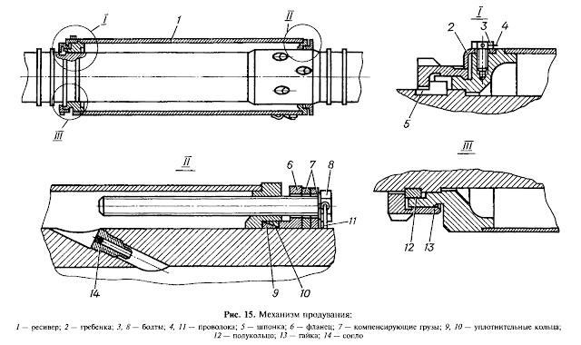


The T-72B3 builds upon the T-72B with the inclusion of the 2A46M-5 gun (D-81TM-5), which was first introduced in 2005 and used in the T-90A. The 2A46M-5-01 can be considered to be the most sophisticated model of the entire series thus far, but the improvements applied to this model are not known.
The dynamic balancing of the barrel during the firing procedure (while the shell is still in the barrel) was better tuned, thus minimizing oscillations at the muzzle. The barrel itself was improved with an increased rigidity of 4,118 N/cm (420 kgf/cm), which is 10.5% times greater than the 2A46M barrel. This serves to reduce oscillations transmitted through the suspension of the tank when it is driven over rough ground, thus improving the dispersion characteristics of the gun when fired on the move. Moreover, the maximum rated chamber pressure was increased to 608 MPa to permit the use of new APFSDS ammunition. According to the manufacturer, dispersion of all shell types by an average of 15% to 20%, and the accuracy when firing on the move has been increased 1.7 times, thanks to the greatly decreased vibration of the gun the tank is in motion over rough ground. Overall, the estimated probability of hit in combat was increased by 20-29% for APFSDS ammunition, 4-12% for HEAT ammunition, and 21-38% for HE-Frag ammunition.
As you can see in the photo below, the location of the recoiling mechanism elements remained unchanged from the 2A46M. The main differences were not so obvious. More photos of the 2A46M-5 are available on Stefan Kotsch's website.

The drawing below (from here) showcases the location of the recoil buffers and the recuperator in relation to the axis of the cannon barrel. The drawing is probably valid for the 2A46M as well.


A basic T-72 including the T-72 Ural and T-72 Ural-1 models can carry a maximum ammunition load of 39 rounds. This was increased to 44 rounds in the T-72A, and increased again to 45 rounds in the T-72B. In all T-72 models, 22 rounds were carried in the autoloader carousel as the ready supply, while all of the remaining ammunition was kept as a reserve supply. The reserve ammunition would be loaded into the autoloader carousel whenever it is necessary, but only when local security has been established. Replenishment of the autoloader from the reserve supply during combat is not practiced - it is much more expedient and much quicker to directly load the main gun manually.

The T-72 uses an "AZ" type electromechanical carousel-type autoloader with a 22-round capacity. All 22 rounds are stored in individual cassettes arranged radially around a central hub which houses the carousel rotation motor and drive as well as the power supply for the turret. The autoloader was modernized in the T-72B to missiles to be carried. The new autoloader had higher reliability, and could also store longer projectiles. We will first examine the original Ural autoloader (known as the AZ-172), and then examine the newer T-72B autoloader (known as the AZ-184) in the context of the improvements that were introduced to the original model. The patent for the T-72B autoloader (Russian Patent No. 2204776) is available here. As mentioned earlier in this article, the gunner controls the autoloader from a control unit located on the TPD-K1 sight, and the commander has his own set of controls.
According to the memoirs of Leonid Kartsev, the AZ-style autoloader was developed independently by the UKBTM design bureau after Kartsev inspected a T-64 during its trials and felt "trapped" by the ring of ammunition surrounding the turret ring, noting that the crew in the turret had no form of contact with the driver besides the intercom system. Upon his return to Nizhny Tagil, he ordered the creation of an autoloader system with a different scheme of ammunition stowage with the intent of surpassing the MZ autoloader, resulting in the AZ autoloader. This new autoloader was first fitted to the Object 167M before being implemented in the Object 172 and then finalized in the T-72 Ural as the AZ-172. The AZ autoloader traded the larger 28-round capacity of the MZ autoloader for an all-electric motorized system, a slightly reduced 22-round capacity and a lower profile. The nuances of this autoloader will be the topic of discussion.

During an engagement, the following occurs:
It is claimed in the memoirs of Leonid Kartsev that this was superior to the T-64A as the spent shell stub was a significant source of propellant fumes from smoldering residue inside the stub, and that disposing of the stub reduced the concentration of fumes in the fighting compartment. There is truth to this claim, as video evidence has shown that even when there is virtually no escape of fumes from the cannon breech after firing (indicating that the fume extractor is working well), the spent shell stub may still pollute the fighting compartment until the smouldering propellant residue is completely burnt. This video is a good example of this. We can also see from videos of artillery crews that this is also true for fully cased unitary ammunition, so the immediate ejection of the spent shell stub from the turret of the T-72 is beneficial to the working environment of the crew. However, the opening of the ejection port exposes the crew compartment to unpurified air in an NBC contaminated environment, which was avoided with the stub return mechanism of the T-64 autoloader. Nevertheless, the contamination from the ingress of irradiated dust particles was considered to be at acceptable levels, which was satisfactory for the Soviet Army as the prevailing concern was to be able to operate in a nuclear-contaminated battlefield, with chemicaland biological contaminants being of secondary importance.
It is important to note that the creation of 125mm semi-combustible cartridges was tied to the development of semi-combustible ammunition for the 115mm D-68 gun for the T-64, and the core rationale for the use of this type of ammunition instead of conventional metal-cased ammunition was to facilitate the operation of the autoloader by eliminating the inconvenience of handling a large empty spent case, as well as the inconvenience of wasting the space it took up if it was simply ejected onto the floor of the fighting compartment. For the T-72 autoloader, these benefits only manifested in a very minor capacity, because the stub is ejected. The small size of the stub is helpful in that it is not obstructive to the cassette when it is lifted up to the ramming position, because the ejection mechanism has limited clearance with the cassette. The small size is also beneficial in case the stub catcher mechanism fails to catch the stub, and it falls onto the carousel cover. If this occurs, there is no interference with the loading cycle.
Each shell and propellant charge stored within the carousel is housed within a two-tiered steel ammunition cassette with extended bills to properly line up the shell or propellant charge with the gun chamber. The diameter of the carousel spans the width of the hull. Below, you can see the ammunition cassettes being dropped in place on a T-72B3 autoloader carousel frame. The carousel rotates independently of the turret and the cover on top of it during both normal and manual operation. Rollers are installed on the carousel frame to ensure that it rotates smoothly along the cover.

The notch on the edge of the central hub marks where the tray lines up flush with the trapdoor on the carousel cover. The notch allows projectiles that are physically longer than the ammo cassette to pass through the trapdoor. As shown in the two photos below, the carousel itself is a simple skeleton frame made from welded steel tubing and pressed sheet steel and is relatively lightweight. The central hub of the carousel fits around the power distribution unit which supplies power to the turret.


The diameter of the autoloader carousel is around 1,800mm and the height of the carousel is around 450mm. The reason for the smaller capacity of the AZ autoloader compared to the MZ series used in the T-64 and T-80 series is structural in nature; both autoloaders array the projectiles in a circle, but the AZ carousel also arrays the propellant charges. Having a larger diameter, the size of the circle that can be arranged is therefore smaller, so fewer rounds can be stowed. Because of this, the AZ autoloader has a smaller capacity despite having the same diameter as the MZ autoloader.


The maximum length of each cassette is 680mm, which is just 2mm longer than the HEAT projectiles carried by the T-72 like the BK-14 and BK-18, and only 5mm longer than HE-Frag shells like the OF-19. The APFSDS ammunition supplied to tanks during the Cold War was the shortest among the three main ammunition types, and even the 3BM-46 "Svinets" projectile fits easily into the ammo cassette.

Modified cassettes are used in the T-72B carousel in order to accommodate guided missiles. The modified cassettes have special latches on both sides accommodate guided missiles and to prevent the stabilizing fins of the missile from accidentally deploying when the missile is rammed into the cannon.

Although the new cassettes are designed to accommodate guided missiles, the length of the cassettes remain at 680mm, so the 9M119 guided missiles (695mm long) supplied to T-72B tanks will overhang the cassette by 15mm. The main factor enabling guided missiles to be carried in the autoloader carousel was not the modified cassettes, but the reduction of the diameter of the hub of the carousel. Thanks to the provisions for accommodating anti-tank missiles, APFSDS rounds of higher elongation are compatible with the AZ-184 autoloader.
The well-known author Steven J. Zaloga claims that there were some problems with zeroing the sighting system and the cannon because the sight was independently stabilized, and the vertical stabilizer for the cannon would sometimes fail to synchronize with the stabilizer unit in the sight as the cannon resets to its original position when finishing its loading cycle. However, it is doubtful if this issue truly exists, because the stabilizer for the cannon is slaved to the independently stabilized TPD-K1 sight and the fire control system features electronic fire gating via a rotary transformer on the gun trunnion, so the stabilizer will always attempt to lay the cannon as close as possible to the aiming point of the sight and permit firing only when there is coincidence between the sight and the gun within a margin of 0.5 mils. The alignment will never be perfect, because the weapons stabilizer is less precise than the stabilizer for the sight. Zaloga may have mistakenly labelled the small alignment error between the two cross-linked systems as a design flaw.
The autoloading cycle requires the gun to be locked at a pre-programmed elevation of +2°30' (+2.5 degrees) which is done so automatically as the cycle begins. During the reload cycle, a cassette is elevated to the ramming position by an electric chain-driven elevator, and the two-part ammunition is rammed into the gun breech. First the shell is loaded, and the propellant charge follows. Because the cannon automatically elevates by +3.5 degrees at the beginning of the reload cycle, the top half of the autoloader elevator is slightly tilted by the same angle to bring the cassette into alignment with the breech. The slight tilt is visible in the diagram below. The diagram shows a T-72 Ural type autoloader. The T-72B has a modified carousel, but the autoloader is otherwise identical.

The electric carousel rotation motor is shown in the cutaway drawing below. The motor is installed on top of the carousel top cover and the ZU-172 memory unit that records the position of each round stored in the autoloader (among other things) is mounted on top of the motor.

The electric motor for the ammunition cassette elevation mechanism is installed on the ceiling of the turret. The use of an electric ammunition cassette elevation mechanism instead of the hydraulic system of the MZ autoloader enables the volume of flammable hydraulic fluid located close to the ammunition to be reduced, thus indirectly increasing the survivability of the tank.
Propellant charge casing stubs are automatically ejected by a stub catcher through a small port at the rear of the turret, visible below:

The stub catcher mechanism registers the presence of a casing via a switch installed in a paddle-shaped arm located behind the stub catcher, shown in the drawing on the right. The paddle-shaped arm also keeps the stub from falling out the back of the stub catcher. When a casing stub is ejected from the cannon, it hits a pin (4) at the back of the paddle-shaped arm which lifts a conductive flat spring (5) off an electrical contact (6), breaking the circuit and prompting the system to register the presence of a propellant charge casing stub in the stub catcher mechanism.

When the gunner activates the autoloader to load the cannon, the stub catcher mechanism is lifted to the ejection port in the turret roof by a linear actuator installed underneath the breech housing of the gun, and the stub is ejected by a pair of ejector levers, powered by a torsion bar. As the ejector mechanism is lowered back into its position behind the breech, the torsion bar for the ejectors is rewound. The paddle-shaped arm is swung away to the side (in the direction of the gunner) by the ammunition cassette elevator to make way for the ramming mechanism.

If the ejection port does not open or opens with improper timing due to an electric or mechanical issue, the ejected case stub may only fall back into the tank without the possibility of harming either the commander or gunner.
When loading the cannon manually in the total absence of electrical power, the spent casing stub held in the stub catcher mechanism is removed by manually pulling the paddle-shaped arm away. After that, the casing stub can just be pushed out the back of the stub catcher and thrown away or stowed away somewhere in the tank. The spent casing stub shold be removed after every shot when firing the gun manually. If not, the casing stub from the next shot would hit the previous stub and fall down onto the carousel cover. Firing without removing the case stub is permissible in emergencies but should be avoided. The photo below shows a case stub being removed manually.

Unlike what most people assume, it is completely possible to unload the cannon after a shot is already loaded. Although not always necessary, this may be useful when two different threats appear one after another. For instance, enemy infantry may appear after the T-72 has finished dealing with an enemy tank, so switching to HE-Frag will be necessary. If an APFSDS round is still loaded in the cannon, it will have to be unloaded either by returning it to the autoloader or firing it off, perhaps into the previously knocked-out enemy tank to ensure that it is truly disabled. If it is desirable to conserve APFSDS ammunition, then the loaded round should be unloaded from the back end of the cannon rather than the front. This can be done by simply using the commander's autoloader control box. The empty ammunition cassette is raised from the carousel, whereby the commander can open the breech manually using the breech operating handle. The ejection of the propellant charge is done automatically by an ejector built into the cannon. The action of pulling the breech operating handle opens the breech and returning the breech operating handle to its stowed position manually activates the ejector to push the propellant charge out of the chamber. The chambered projectile is not ejected; it must be extracted by hand. The propellant charge and projectile are inserted into the empty cassette and returned to the autoloader carousel. After this, the gunner can continue the target engagement process as normal. The amount of time needed to complete this operation is non-trivial, but it is absolutely possible if the situation calls for it.

The autoloader is able to recognize the position of each round stored in the carousel using the carousel storage memory unit, as shown below (ZU-172 model for the AZ-172 autoloader). Three ammunition types can be indexed into the carousel in this model. This device is mounted next to the trapdoor of the carousel cover, at a position where the commander can access it easily when replenishing the carousel.

To load ammunition into the autoloader, the commander must use his control box to cycle between cassettes. After loading a cassette, he must input the ammunition type into the memory unit by pushing one of three buttons, one for each type of shell: HEAT (К), APFSDS (б), or HE-Frag (O). When any one of the three buttons is pushed, the memory unit records the corresponding ammunition type and returns the cassette to the carousel, then the carousel spins to the next empty cassette.

The memory unit indexes the type of ammunition on a data disc stored inside the circular housing. The type of ammunition is identified using a binary system on the data disc. There are four magnetic rings on the surface of the disc. The rings are divided into a total of twenty two groups; one group for each round stowed in the autoloader carousel. Each group consists of three sets of four ring sectors. In each group, four of the sectors are for recording the type of ammunition (ammo set), four are used to determine when to brake the carousel rotation motor (braking set), and four are used to determine where to stop the carousel in order to line up the ammunition to the trapdoor (stopping set). Each sector stores one bit of data. As there are twenty two groups with twelve data recording elements capable of storing one bit each, the data disc is considered to have a storage capacity of 264 bits.

When replenishing the carousel, recording the ammunition information is done by three current carrying pins connected to the magnetic rings via electrical contacts. Data storage is done by changing the polarity of the sector groups to either positive or negative using the electrical contacts. The electrical contacts are spring loaded to keep them in contact with the magnetic rings to ensure that reading and writing the data is still possible even while the device is experiencing strong vibrations such as when the tank is on the move over rough ground or after the tank is hit with the shockwave of an explosive blast. However, the constant pressure wears out both the magnetic ring and the electrical contact over time as the contacts rotate over the disc, leading to a loss in the ability to record and read data, and the conductive metallic dust produced by the rubbing of the contact on the ring surfaces can contaminate other parts of the unit, causing reading errors. Such errors could prevent the autoloader from accepting new ammunition when loading it, or cause the autoloader to lose track of where ammunition is stored or even to "forget" when to stop rotating the carousel if it is already in motion, so that it rotates indefinitely. Even if the recording surfaces are not worn out, it is also possible for the device to fail from the accumulation of dust and grime over time. At this point, it is possible to either replace the electrical contacts on the hard disc, or replace the entire memory unit. This is an easy task that can be done in the field as long as a spare memory unit is available, as the replacement of the unit only requires that the old one has its electrical cable unplugged.

The rotation of the reader contacts around the fixed data disc is not powered by an internal motor, but rather, is driven by the carousel rotation motor via a gearbox leading to shaft passing through the bottom of the memory unit.
The design of the data disc is clearly an extremely simple and archaic form of hard disc storage with an extremely low storage capacity. The lack of sophistication, however, is completely justified by the lack of a need to store a large volume of data and the high robustness required of the system. The simple design of the memory unit grants high resistance to shock and mechanical damage, and its self contained housing facilitates quick replacement if it is damaged. Apparently, one of the most common source of autoloader malfunctions is the memory unit.
Due to the limit of three ammunition types, this memory unit is not used in the T-72B, as there is a new type of ammunition: guided missiles. According to the patent for the T-72B autoloader (Russian Patent No. 2204776), the memory storage was upgraded to accept a fourth ammunition type; missiles. The upgraded memory storage unit was also improved for better reliability.

To record a fourth ammunition type, the data disc features five magnetic rings instead of four. The first sector in the ammo set records an empty cassette, while the other four record ATGM, APFSDS, HEAT and HE-Frag. The storage capacity increased to 330 bits. Additionally, this new memory storage unit features a new input mechanism with a rotary dial instead of three buttons. The method of reading and recording data is functionally the same, differing only in how the mechanism functions. The dial has four positions for the four ammunition types. To select and index an ammunition type, the dial is turned to one of the four positions, and then pressed. The position of the dial serves to position a mechanical stop, to limit how far the writer contact can travel along the disc. When the dial is pressed, a servomotor is activated to move the writer contact until it hits the stop, and then a current passes through the writer contact. Whichever sector the contact is laid upon will be energized. In this way, one of the five sectors will be switched to a one value while the others remain with a zero value, thus recording one ammunition type.
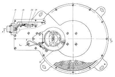

Restocking the T-72 with a full load of ammunition including both the autoloader and the rounds held in loose stowage reportedly takes 13 to 15 minutes. By comparison, the T-64A (and its successors) requires 25 to 27 minutes to do the same despite the much smaller complement of ammunition stowed outside of its autoloader, probably because the rounds are stowed outside the autoloader carousel "basket" and access to the hull from the turret cabin is extremely limited.

The stowage layout for the T-72A is presented in the diagram below (44 rounds in total). The diagram is from a T-72 weapons handling manual. There are 16 projectiles stowed in the hull, and 6 projectiles in the turret, on top of the autoloader carousel. There are 17 propellant charges in the hull, and 5 in the turret, on top of the autoloader carousel. A total of 5 stowage points are laid vertically and are reserved for APFSDS rounds - 2 in the hull, and 3 in the turret.

The layout for the T-72B is shown in the diagram below (45 rounds in total). The diagram is taken from a T-72B manual. As you can see, the stowage layout is largely identical to the T-72A, with a few changes. A positive change in the T-72B ammunition layout is that the number of cartridges stowed in the turret was reduced, moving more ammunition into the hull instead. 18 projectiles are stowed in the hull, and 5 projectiles in the turret, on top of the autoloader carousel. 19 propellant charges are in the hull, and 4 are in the turret, on top of the autoloader carousel. 2 shells are stowed in racks on the turret wall, on the gunner's side. Only 3 stowage points in the tank are laid vertically and are reserved for APFSDS rounds.

Almost all of the propellant charges - the most vulnerable half of the two-part ammunition - are stowed in cylindrical slots inside the conformal fuel tanks. There are twelve slots in the large fuel tank behind the autoloader carousel for propellant charges. Due to the excellent location, the charges are almost completely safe - the carousel would always be in the way instead unless the tank was hit from behind, and it is extremely difficult to hit this fuel tank from above due to the location of the autoloader elevator mechanism and the crew seats. The drawing on the right below shows the propellant charge inside one of the slots. Note that the only the steel casing stub is exposed while the combustible charge casing is fully enclosed by the fuel tank. The drawing on the left shows the arrangement of slots in the fuel tank. The depression at the left hand corner of the fuel tank is made to help accommodate the shells clipped to the side of the hull.


The location of the fuel tank at the rear of the fighting compartment of a tank without the autoloader carousel is shown in the photo below. Note the small red TD-1 flame detection sensor at the lower left corner of the photo, next to the fuel tank.

This stowage method minimizes the risk of immediate deflagration from open flames inside the tank because only the non-flammable steel casing stub is exposed. Of course, this arrangement is not completely fireproof, but it may give the crew enough time to evacuate the tank or extinguish the fire before it becomes too serious. The commander can access the propellant charges stowed in the fuel tank by either swinging the backrest of his seat forward (in the T-72 Ural and T-72A) or by pivoting the backrest of his seat to the side (in the T-72B) as shown in the photo below. The newer pivot arm mechanism on the T-72B allows the commander to stay seated as he access the ammunition at the back of the tank and loads it into the cannon, thus reducing fatigue and possibly increasing the rate of fire of the tank when using manual loading.

The right hull fuel tank on the right hand side of the driver has slots for three propellant charges and either four shells (Ural) or three shells (T-72A, B) plus a single exposed propellant charge stowed in a circular cup at the back of the fuel tank. The right hull fuel tank is shown in the photo on the left (rotated to represent the actual orientation of the fuel tank in the hull) and a cross-section of the propellant charge slot in the fuel tank is shown on the right side. Note that the rim of the propellant charge is not laid flush to the surface of the conformal fuel tank slot unlike the conformal fuel tank at the back of the fighting compartment. This is because the charges are held horizontally so there is very little danger of burning liquid flowing into the slot.
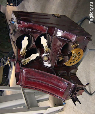

Cross-sections of the slots for the shells in the front right hull conformal fuel tank are shown in the diagram below. Two versions of the rack exist - the original type with four slots, used on T-72 Ural tanks, and the new type with three slots, introduced on the T-72A in 1979 and used in all subsequent models. The slots were designed with the dimensions of HE-Frag and HEAT shells in mind and were built exclusively for them. Stowing any ammunition types other than HE-Frag and HEAT in these slots is prohibited. The projectiles are securely fixed in place and do not slide out forward, as a latch holds it by the fin retention band from the front, while a cresent-shaped rotating cover stops the projectiles from sliding rearward. As there are no folding fins and no retention band on APFSDS ammunition and guided ATGMs, they cannot be secured within these racks.


To load projectiles into these racks, the cresent-shaped cover is rotated so that it clears an opening into an empty slot. Then, the spring-loaded latch is held open, and the projectile is inserted up til the fins, and the latch is released so that as the projectile is inserted all the way forward, it stops against the latch. The crescent-shaped cover is then turned away. Extracting projectiles from these racks is simpler, as the crescent-shaped cover only needs to be turned to open, and the projectile can be pulled straight out. The taper on the base of the projectile body will push the latch aside as the projectile is pulled out by its tail.
The location of these racks makes it convenient for the commander when loading the cannon manually, assuming that the turret is oriented forward or to the left. As you can see in the two photos below, the height of the propellant and shell compartments is just above the autoloader carousel. To use these racks, the commander should turn his TKN-3M/MK periscope to the right, lean forward to pull out a shell, ram it in into the gun, and repeat the motion to load the propellant charge. The main ergonomic issue with the arrangement is that the large ammo box for the coaxial machine gun is in the way, so the commander has to lean underneath it unless the turret is turned to the left.


More shells and propellant charges are stowed on top of the carousel cover. Some of the propellant charges and shells are clipped to the cover, and others are placed vertically and clipped to the turret ring. There is one position at the 11 o'clock sector of the carousel cover where a single shell can be clipped onto the cover lying down. This shell may obstruct the driver from moving to the gunner's position, or the gunner from pulling the driver out of the tank through the turret.

The circular "ashtrays" at the back of the carousel at either side of the trapdoor are where the shells and propellant charges are placed upright. The shells are secured using clips attached to the turret ring. The "ashtrays" can be seen in the photo below, but the diagrams from the manuals are much more useful. It is shown that two pairs of shells and propellant charges are stowed to the left of the carousel trapdoor, behind the backrest of the commander's seat. Here is one "ashtray" between the autoloader cassette elevator mechanism and the gunner's cannon breech guard. This is the same one as seen in the photo above, to the right of the carousel cover trapdoor. The conformal fuel tank at the rear of the fighting compartment can be seen in the background.

To access the ammunition behind the seats of the gunner and commander, they must scoot forward in their seats and swing the backrest forward. Only then can the shells be unclipped and extricated. Since there is ammunition on both sides of the turret, both the commander and gunner can manually load the cannon if the situation calls for it.
The two pairs of shells and propellant charges stowed on the racks on the carousel cover are located behind the commander's seat. The clips that secure them to the turret ring can be seen in The Challenger's video review of a Czechoslovakian T-72M1 tank. These rounds are very easy to access. The commander only needs to swing or pivot the backrest of his seat out of the way, and then he can directly load the cannon or replenish the autoloader carousel in short order.

The degradation of the propellant charges stowed out in the open atop the carousel cover is reduced by the inclusion of a protective metal sleeve that fits over the exposed combustible nitrocellulose-impregnated cardboard charge casing just over the metal casing stub. The sleeves are meant to protect the combustible charge from environmental damage, but these sleeves also offer a modicum of protection from open flames.

Eight shells can be stowed on the engine compartment bulkhead, on top of the conformal fuel tank behind the autoloader carousel. Three more shells are clipped to the wall on the side of the hull, on the gunner's side. The shells are secured to the ammunition racks using clips. All of the stowage spaces on the engine compartment bulkhead and on the side hull wall are visible in the screenshot below (T-72B type tank hull on display). The gunner can easily access the shells clipped to the side of the hull, but only if the turret is turned slightly to the left.

The drawing below shows the racks. These racks can accommodate all ammunition types, including missiles as the drawing on the right shows (taken from a T-72B manual).


The commander can freely access the shells clipped to the wall at the back of the fighting compartment. Thanks to the lack of a turret basket on the T-72 turret, the commander can simply swing the backrest of his seat out of the way, unclip one of the shells, and then bring it up to the cannon to ram it in. He can then lean down and extract one of the propellant charges from the conformal fuel tank behind the autoloader carousel. The ease of accessing the ammunition in loose stowage heavily contributes to the relatively high rate of fire when loading manually and also reduces the time needed to replenish the autoloader carousel.
It is also worth noting that the APFSDS rounds are protected by a metal sleeve when stowed on the clips, as they have an incremental propellant charge attached to the sabot and thus have some need for the additional layer of protection during stowage. The photo below seems to show one APFSDS round with a green sleeve.

The screenshot below gives us a good view of the ammunition from the driver's perspective, so while it may appear that a shell penetrating the hull armour would seriously jeopardize the ammo, this is not necessarily the case. Due to the highly cluttered fighting compartment and the very large distance from the upper glacis armour to the ammunition mounted to the wall (more than two meters), the ammunition has a very good chance of avoiding any damage whatsoever. The photo below, for example, is the same view taken from the same angle, but it is clear that the engine compartment bulkhead is completely obscured behind the stabilizer components underneath the cannon and behind the seats of the commander and gunner. If the tank hull is penetrated from the front, the tank will likely be knocked out by a firepower kill via damage to the stabilizer or some other component of the gun control system, but an immediate ammunition detonation may be avoided and the crew may survive.

Although the loose ammunition stowed in the turret and hull is quite vulnerable, it is important to recognize the fact that some attention was paid to their protection. Most of the vulnerable propellant charges are held inside the conformal fuel tanks and those that are stowed in the open are at least protected by a fire retardant sleeve. These measures offer some protection from open flames. The projectiles held in loose stowage are not protected by similar measures, but they are already fire resistant to a large extent with the exception of the APFSDS rounds.
Furthermore, it is also clear that the ease of access to the ammunition held in loose stowage was a major ergonomic consideration during the design of the tank. The location of these rounds and the amenities provided to access them facilitate the speedy loading of the cannon and replenishment of the autoloader carousel. In the event that the commander is incapacitated or dead, the ammunition on the gunner's side of the turret is laid out in such a way that he could also load the gun manually in an emergency, but with only a few cartridges at hand, this cannot be sustained for longer than just a few shots.
All in all, there can be between 17 to 23 additional cartridges stowed outside the carousel for a total of between 39 to 45 rounds of ammunition depending on the specific model of T-72. However, in practice, crews tend to ignore certain spaces such as the shell stowage rack on top of the carousel cover (as seen above), and some crews may decide not to have any ammunition in loose stowage at all, so the actual sum total of loosely stowed ammunition can be anywhere from 22 to none. For example, a tactic developed in the modern Russian Army called the "tank carousel" or the "merry-go-round" involves the use of a platoon-sized unit (three or four tanks) with fully loaded autoloader carousels to engage enemy forces from pre-planned positions until they run dry. Then, they withdraw a short distance to replenish their ammunition from waiting trucks and allow another platoon of three or four tanks to immediately replace them. No ammunition is carried outside of the autoloader carousel, and the tanks always fire from hull-down positions.
Nevertheless, from a design standpoint, the fact that the T-72 can have a total ammunition capacity of 45 rounds when the older T-54/55 with a 100mm cannon had 43 and the T-62 with a 115mm cannon had just 40 was a noteworthy achievement in tank design efficiency. Compared to the Leopard 2 (42 rounds) and M1A1 Abrams (40 rounds), the T-72 carries more ammunition overall for a cannon of a similar caliber and power. Considering that many amateur tank enthusiasts and even historians like to espouse the higher ammunition capacity of early Cold-War era NATO tanks as a decisive advantage over the Soviet T-54 and T-62, the fact that the T-72 carries more ammunition than its contemporaries is curiously ignored.
Surprising as it may be, the T-72 also carries more ready ammunition than its two most modern NATO counterparts as it has 22 rounds in the carousel compared to 17 and 15 rounds in the bustle ready racks of the M1A1 Abrams and Leopard 2 respectively. Moreover, only 12 rounds are immediately accessible in the bustle ready racks of the M1A1 before the loader must start collapsing the racks to access the cartridges that are out of reach, while only 6 rounds are immediately accessible in the Leopard 2. The ammunition capacity of the autoloader carousel is the same as the autoloader bustle of the Leclerc, and the Challenger 2 carries a few more rounds in its ready racks (25). Generally speaking, this is not an issue for any of these tanks because it is rare for a tank to expend so much ammunition in a single engagement. There is typically a lull in the fighting, which is when the loader in any tank would take the time to replenish his ready racks from the less accessible reserve ammunition racks. In the case of the T-72, the commander and gunner will replenish the carousel using the loose ammunition stowed inside the tank in the turret and hull.
In an Abrams, the commander will have to open the bustle door on his side of the turret and pass cartridges over to the loader who will then stow them in the ready racks in his side of the turret bustle. It's worth noting that the sliding door for the bustle reserve rack in all variants of the Abrams did not have a hydraulic mechanism like the loader's ready rack door. The commander must manually crank open the heavy armoured door in order to access the ammunition, making it impractical and dangerous to use this rack as a substitute ammunition supply during combat.
In a Leopard 2, the loader will have to take ammunition from the front hull racks and stow them in the bustle ready racks, and this is only possible when the turret is oriented in a specific sector as the front hull racks would otherwise be inaccessible to the loader.
However, ammunition carried in loose stowage can be a huge liability in battle as it has been proven to be the main cause of irrecoverable or catastrophic tank losses. Some of the loose ammunition stowed in the hull is still somewhat secure, but the ammunition in the turret constitutes a significant risk to the survival of the crew. As the diagram below shows (diagram taken from Tank-Net), only 2% of shots land at a height of one meter from the ground in the 60 degree frontal arc of a tank. This is good news for the carousel autoloader, but the diagram shows that 65% of shots hit the turret. As such, the benefits of the low placement of the carousel may be completely undone by loose ammunition stowed in the turret.

However, it should be understood that the distribution of hits fluctuated somewhat over the years in various conflicts. In the Second World War, the majority of hits sustained by tanks were on the hull. It is commonly thought that this was due to the fact that the hulls of the tanks of the era tended to be much larger than their turrets and also quite tall due to the placement of the transmission at the front such as on the Panther and M4 Sherman. Later on, combat in Korea and in the Middle East showed that the share of hits recorded on the turret increased, creating a more even distribution of hits between the turret and hull. It is worth noting that the average combat distance in Korea was very short - only a few hundred meters - due to the nature of the terrain. Later on, it was observed by Dr. Manfred Held that in Kuwait during Operation Desert Storm (ODS), the vast majority of shots landed on the turret. The diagram below, taken from "The Main Battle Tank of Russia: A Frank Conversation About The Problem of Tank Building", shows the distribution of hits in the vertical plane by percentage for the 1967 Six-day war, the 1983 Yom Kippur war and ODS in 1991.

The three black bars in the diagram indicate (from top to bottom) the bottom of the turret, the belly of the tank, and ground level. The bottom of the turret - the turret ring - is considered to be 1.5 meters above ground level, and the belly of the tank is considered to be around 0.5 meters from ground level. The hull is therefore considered to be around 1 meter tall. This is a representation of a Soviet main battle tank like the T-72, T-64 or T-80. All of these tanks have a ground clearance of 0.48 meters, a hull with a height of 1.0 meters, and a turret ring located 1.48 meters above ground level. Considering that the AZ autoloader carousel has a total height of 450mm (including the top cover), the total height of the carousel from ground level is 940mm.
As you can see, even though the distribution of hits was not entirely consistent across the three conflicts, the fact that the lower half of the hull (between 0.5 to 1.0 meters from the hull belly) statistically sustained the fewest hits was universally true for all cases, and therefore, the autoloader carousel would sustain very few direct hits. The turret ring zone sustained the greatest number of hits statistically, which makes sense as the turret ring is the center mass of any tank. These observations are further reinforced by statistics on the hit distribution on combat-damaged tanks during WWII on the Eastern Front, where 90% of hits on Red Army tanks were recorded at a height of one meter above the ground, as reported by Sergey Gryankin on pages 12-13 in his article "T-54", published in the "Техника-молодёжи" magazine (Technology of the Youth). Again, this shows that the lower half of the hull would receive the vast minority of hits under combat conditions. From this, it can be seen that the majority of damage inflicted to the autoloader carousel in the event that the armour of the T-72 is defeated would be from projectile fragments or secondary fragments coming from above, i.e from the upper sections of the upper glacis or from the turret. These fragments would be attenuated by the "Podboi" anti-radiation liner. The air gap between the surfaces of the upper glacis and the turret further reduces the energy of fragments, and the carousel itself provides protection for the ammunition contained within.
Furthermore, it can be inferred from the hit distribution figures that omitting some of the ammunition carried in the turret would be eminently beneficial to the survival of the tank and its crew in the event that the turret armour is pierced. And indeed, as mentioned before, this was widely practiced by Russian tank crews during the wars in Chechnya along with new tactics such as the "tank carousel", which was developed to maximize the firepower of a tank platoon while minimizing exposure to enemy fire and minimizing the possibility of a hit to the ammunition. The concept of removing all ammunition from the turret to improve crew survivability was validated after data was collected from the wars in the Middle East. This lesson was institutionalized in the U.S Army as expressed by Colonel Robert E. Butler, project manager of M60 tank development, in his article "M60A3 Tank Program" published in the July-August 1977 issue of "ARMOR" magazine. On page 43, he details that the wars in the Middle East showed that a large percentage of tank hits were above the turret ring, and that in an effort to lessen the vulnerability of the M60A1, a program was initiated to relocate all the 21 rounds of main gun ammunition located in the turret bustle to the hull and research was conducted on installing a nylon or kevlar spall lining for all of the main gun ammunition.
Another noteworthy aspect to consider is the mine resistance of the autoloader carousel. The carousel of the AZ autoloader is mounted to the floor whereas the carousel of the MZ autoloader of the T-64 and T-80 is suspended from the turret and the autoloader itself is housed in the turret cabin. Only the rotary power supply unit connects the turret cabin to the hull floor. The extent of the difference in durability is difficult to determine, but it seems unlikely that a mine blast underneath the tank will disable the autoloader as a conventional anti-tank mine with a tilt-rod fuse would detonate under the driver's station and an anti-tank mine with a simple pressure fuse would detonate under the tracks at the first roadwheel. The shock from the explosion may potentially be a source of failure, but it would only be fair to point out that the power supply unit (for any tank) may be damaged as well as it is mounted to the belly. In that case, the power supply to the turret would be cut off and the loss of autoloader function becomes a much less serious issue by comparison.
If the autoloader elevator malfunctions, it is still possible to operate the elevator mechanism manually using a crank wheel (pictured). The commander and the gunner may have to take turns to load the cannon depending on the location of the ammunition in loose stowage. The commander would obviously load the cannon using ammunition close to him, and vice versa. Some of the ammunition requires the turret to be oriented in a specific direction to access. The T-72A manual has a full table detailing the locations of the ammunition, the orientation of the turret needed to access it, and whose responsibility it is to load that ammunition. The benchmark time for a complete manual loading cycle is 26 to 30 seconds. The corresponding time for a T-64A as dictated in a manual is 1 minutes 40 seconds for the first shot and 1 minute for subsequent shots. In other words, a T-72 is able to sustain a rate of fire of around 2 rounds per minute with manual loading whereas a T-64 would struggle to attain a rate of fire of 1 round per minute. However, according to official Soviet norms (battle drills), the minimum acceptable times for loading in a T-72, T-64, and T-80 are all the same. The "minimum" grade for manual loading using ammunition from the ammunition carousel is for 1 minute, the "good" grade is for 50 seconds and the "excellent" grade is for 45 seconds.

If the carousel fails, it is possible to manually crank the carousel and access the ammunition inside using a cranking lever located underneath the commander's seat. However, the commander would have no idea where the desired ammunition type is located in the carousel, so it may be more feasible to simply use the ammunition in loose stowage.
Both the gunner and commander have free access to the autoloader from their respective stations. As such, it is possible for the crew to troubleshoot the device without leaving the tank or requiring the separation of the turret from the hull. The old Soviet promotional image below shows a tanker in the gunner's seat with his hands on the autoloader elevator and the stub ejection mechanism.

Manual loading is something to be done in emergencies only, not only because it is much slower than normal automated loading, but because it also forces one of the two crew members to abandon his usual duties. In reality, autoloader failures are exceedingly rare (but not non-existent), so there is little need to worry about manual loading. The propensity for autoloaders to malfunction either from wear and tear or from a knock on the turret tends to be greatly exaggerated.

There are four main types of ammunition for the 125mm gun. A typical loadout for a general infantry support mission would see that HE-Frag shells are loaded in large quantities, for example, while more HEAT and APFSDS shells would be loaded for ambushes where armoured vehicles are expected. A standard ammunition load would comprise of an equal mix of high explosive rounds (HE-Frag) and anti-armour rounds (APFSDS, HEAT) with APFSDS rounds being much more numerous than HEAT rounds. A standard mixture for a T-72 Ural is detailed in the 1979 manual "Crew Operations Manual for the Weapons of the T-72", where out of a total of 39 rounds of ammunition, there should be 19 rounds of HE-Frag ammunition, 14 rounds of APFSDS ammunition, and 6 rounds of HEAT ammunition. As for the ratio of ammunition carried as the ready supply in the autoloader carousel, there should be 11 rounds of HE-Frag ammunition, 7 rounds of APFSDS ammunition, and 4 rounds of HEAT ammunition.
All muzzle velocity data for the 125mm ammunition listed in this article was obtained with a propellant charge temperature of 15°C.
The steel obturator stub, made from BV-11 steel, is the only part of the cartridge assembly left intact after firing. The stub on 4Zh40 and 4Zh52 charges was designed to withstand a chamber pressure of up to 5,000 kgf/sq.cm, or 490 MPa. In the T-64 and T-80 series, this stub is returned to the autoloader mechanism by a mechanical arm, but in the T-72, this stub is ejected from the tank via a small hatch at the rear of the turret roof. The diameter of the rim is 172mm, the diameter of the opening is 160mm, and its total length is 140mm. It weighs 3.45 kg. The purpose of the casing stub is to contain the propellant and obturate the breech for ensuring a complete seal, so that no flashback occurs.

The use of a relatively large steel casing stub as opposed to a small primer unit like on the bagged charges of the L11 contributed to the relatively hefty ~10 kg weight of each complete propellant charge, but given that the 125mm gun is automatically loaded, this has no negative impact. On the other hand, the effect of the increased mass from the steel casing stub on the 120mm cartridges for the Rh 120 L/44 and M256 guns, which weigh around 3 kg, has a tangible effect since these guns are manually loaded.
The GUV-7 electric-percussion primer is used in all of the three propellant charges designed for the D-81, giving the option to either fire the shell normally using the electric trigger on the gunner's control handles, the electric trigger on the manual elevation handwheel, or using the manual lever-operated striker pin incorporated into the breech block of the cannon. The required initiation voltage and current is 20 V and 2 A respectively. Being a combined electric-percussion primer, the firing reliability is extremely high, as there is always a backup in case one initiation method fails for whatever reason. The possibility of percussion initiation is particularly useful as the mechanical firing mechanism built into all D-81 series guns is available even if the electrical systems in the tank are shut down.

GUV-7 is rated to withstand a chamber pressure of up to 5,000 kgf/sq.cm, or 490 MPa. It can, however, be used with high-pressure rounds such as 3BM26 and 3BM42 without issues, as indicated by its continued use in the 4Zh63 propellant charge despite the much higher operating pressures generated.


Original propellant charge designed for the D-81, used since the T-64A. It uses the 15/1 Tr V/A single-channel tubular propellant in uncut sticks and 12/7 V/A seven-channel grains. Both types of propellant have high nitration. The mass of the propellant charge itself is 5.66 kg, while the steel obturator stub weighs 3.45 kg. The remainder is taken up by the combustible nitrocellulose casing and the primer.


Like the standard charges, a coil of lead wire is included together with a satchel of DRP-3 black powder at the top of the charge, and a ring-shaped satchel of VTKh-20 flame arresting powder is placed at base of the steel obturator stub.
Mass of Complete Assembly: 10 kg
Propellant Charge mass: 5.3 kg

The T-72 normally carries a 50% load of HE-Frag shells in the autoloader in a standard combat loadout, although this will almost certainly vary by situation. Traditionally, this type of ammunition is predominant in Soviet armoured shock tactics, where tanks were regarded as the tip of the spear during breakthroughs and many other types of combat missions. This approach was supported by real data showing that combat with heavily armoured tanks was infrequent and that the most common targets tended to be military and civilian structures, infantry and soft-skinned vehicles. HE-Frag shells were therefore a critical part of the combat loadout of any T-72.
Together with HEAT, the HE-Frag ammunition used in 125mm guns is considered a full charge, full caliber round. It erodes the gun barrel at a rate of 0.0033mm per shot.

All 125mm HE-Frag shells were fitted with the V-429E point-detonating fuze. It has two settings - superquick and delayed. The fuze is armed by inertia; setback forces from the acceleration inside the gun barrel trips the arming mechanism, and when the shell experiences a braking effect from the unfolding of the stabilizer fins at a distance of 5 to 7 meters from the muzzle, the fuze is armed.
The fuse gives 125mm HE-Frag shells a great deal of flexibility. There are two fuze settings and the fuze cap can be left on or taken off, giving a total of four fuzing combinations. Of these, three are used. Setting the fuze in a T-72 is done by the commander using a special key if he determines that a different fuzing mode is suitable for a particular target. The key turns a valve that connects the percussion cap of the impact mechanism to the detonator cap. There are two paths for a flame from the percussion cap to travel to the detonator cap: the direct path through the valve, and a parallel path where it ignites a retarder, which then combusts and emits a flame to the detonator cap after some delay.


To use the shell in the "Frag" mode, the fuze is left in the "O" (superquick) setting and the protective fuze cap is removed. With the fuze cap removed, the striker is protected only by a steel foil membrane, which is thick enough to prevent the striker from being blown back by the flow of air, but is too thin to survive a collision with anything substantial. Upon impacting any obstacle, the steel foil membrane, which has a thickness of just 0.12mm, is pierced and the striker is driven into a percussion cap, triggering the detonator. The shell detonates instantly upon impacting practically any surface or obstacle, which can be useful as the tank may fire at the canopy of a tree to produce an airburst over infantry taking cover beneath it. However, it is forbidden to use the "Frag" mode in heavy rain or hail because a collision of the steel foil membrane with big rain droplets is enough to trigger a detonation.
When set in the HE mode, 125mm shells are extremely deadly to lightly armoured vehicles. For example, 76mm HE shells fired from the F-34 cannon of a T-34 were also found to be able to perforate the armour of tanks like the Pz.III. There is comparatively little information available on the internet on this topic, but Peter Samsonov's translation of a report on the effects of 76mm HE-Frag shells at tanks with a variable fuse is especially enlightening. Here is a fascinating paragraph from that report:
"When firing [76mm] HE shells from mod. 1931 guns consider that they can penetrate 45 mm of armour at 30 degrees from 500 meters, and 50 mm of armour under the same conditions can be penetrated from 300 meters or closer."
Like any other anti-aircraft gun intended for engaging high altitude targets, the mod. 1931 gun fired relatively high velocity rounds (~800 m/s), but such velocities are pedestrian for modern guns like the 2A46. It is also worth noting that the shape of HE shells is ogived, so the efficiency of such shells on sloped armour is very low compared to a blunt-nosed APBC shell like the 100mm BR-412B. If 76mm HE shells are capable of defeating 45mm of armour plate angled at 30 degrees at 500 meters, a much larger 125mm HE-Frag shell travelling at the same velocity would be able to penetrate much more or at least achieve a more destructive effect. Indeed, Hungarian testing of 125mm HE rounds on T-34-85 tanks showed that frontal hits could perforate the upper glacis armour and detonate inside the tank with catastrophic effects as shown in the photos below.


Interestingly enough, the 0.063-second delay of the V-429E fuse is identical to the delay of other post-War fuses like the RGM-6 point-detonating fuse for 100mm HE-Frag shells, and this delay is longer than what WWII and pre-war fuses for artillery rounds provided, which was 0.03-0.05 seconds. This was most likely related to the increased standards of bunker fortifications and the disappearance of concrete piercing rounds from the arsenal of the Red Army shortly after WWII.
The side armour of some NATO tanks like the Chieftain and the Leopard 1 are probably vulnerable to 125mm HE shells from combat distances (1.5 km or more) given that their side armour is only 38mm thick, and it is likely that the thicker side hull armour of an M60A1 may not be enough to resist 125mm HE at closer distances. Thin side skirts may offer too little resistance to set off the V-429E fuse, even steel skirts which are found on tanks like the Centurion and Chieftain. The Leopard 1 is noteworthy as the armour on the side of its turret is only 40mm thick (angled at 30 degrees), so even the aforementioned 76mm HE shell fired from the 1931 anti-aircraft gun may potentially defeat the Leopard 1 from 500 meters. The addition of a 30mm spaced appliqué plate on the turret in later Leopard 1 variants might still not be enough to defend it from a 125mm HE shell, and even if the shell was successfully stopped, the explosion might still be powerful enough to split open the base armour plate. Against a heavily armoured IFV such as the M2A2 or M2A3 Bradley, the 38mm layer of steel appliqué armour on the hull will be entirely insufficient to stop such a shell even at long distances. Modern IFVs designed with relatively heavy armour to combat the ubiquitous RPG are probably still extremely vulnerable to 125mm HE.
As such, even though the T-72 carries more HE-Frag shells than anti-armour shells, it can be seen that this is not a problem as HE-Frag shells have a very substantial multi-role capability. It is not wrong to say that the combat value of an individual HE-Frag round easily exceeds that of an APFSDS round or a HEAT round. Nevertheless, it would be misleading to paint HE-Frag rounds as an ultimate weapon when in fact, the 125mm gun of the T-72 was chosen for the high armour penetration of its APFSDS ammunition. Indeed, during testing in the early 60's, it was found that the range and accuracy of HE-Frag rounds fired from the rifled 122mm D-83 gun was superior to the range and accuracy provided by the smoothbore D-81. However, the armour penetration of the sub-caliber ammunition fired from the D-81 was somewhat better which proved to be the determining factor in the comparative trials. The D-81 was given the GRAU index of 2A26 and the D-83 was given the index of 2A27, but only the 2A26 went on to see service in the USSR's new line of advanced MBTs.
Due to the high muzzle velocity of 125mm HE-Frag shells, the ballistic trajectory is relatively flat. This reduces its sensitivity to rangefinding errors and increases its range, but conversely, the low angle of impact of the shell when fired at the ground greatly limits the effectiveness of its fragmentation against infantry in the open, particularly if they are lying prone or in a trench. To maximize the anti-personnel effect, the tank should begin firing at infantry targets at a longer range to maximize the angle of descent and ensure that the shells impact the ground at a relatively low velocity. The gunner may also use ricochet fire to generate air bursts, which is drastically more efficient against infantry than ground bursts. The dispersion of 125mm HE-Frag shells is low enough (considering its purpose) to engage point targets and area targets alike. Combating ATGM systems - both man-portable and vehicle-mounted - occurs at long standoff ranges to prevent return fire. Naturally, this permits the angle of impact to be quite high and the impact velocity to be quite low; the official firing table for the OF-19 shell shows that the angle of descent and impact velocity at 4,000 meters is 3.6 degrees and 454 m/s respectively.
Shot for shot, conventional 125mm HE-Frag ammunition was considerably more effective in a direct comparison with NATO tanks armed with 105mm and 120mm guns excluding the ammunition developed in the post-Cold War era. As a rule, the HEP or HESH rounds found on rifled 105mm and 120mm guns are effective on armoured targets (with homogeneous armour) and reinforced structures, but are ineffective when firing at targets in open ground due to the inertia-based fuzing system and poor fragmentation characteristics of the thin steel warhead casing. Some NATO nations like France used 105mm HE shells, but the large difference in caliber naturally makes them less effective than 125mm shells on a shot for shot basis. The smoothbore Rh120 L/44 and M256 guns were the worst in this regard as HEAT rounds were intended for everything that was not a tank. Given that the Soviet Army was completely mechanized by the 1980's, there was clearly a valid doctrinal reason for the simplification of the combat loadout to only two types of ammunition, but HEAT rounds are still extremely poor against infantry in the open and infantry sheltered in structures or behind cover. Recently, the need for HE-Frag ammunition in tanks armed with a smoothbore 120mm gun was recognized and its role was fulfilled by the DM11 round in German service. DM11 is also used by the U.S Marine Corp as the Mk. 324.
3VOF22

The OF19 shell is a conventional HE-Frag shell with copper driving bands. The casing of the projectile has the shape of an ogive. It is interesting to note that this shell has a length of 675mm, making it the longest projectile among the three ammunition types carried by a basic T-72. This only changed with the inclusion of guided missiles in the T-72B and high elongation long rod projectiles later on.
A stabilizing fin assembly made from B-95 aluminium alloy is used. The forged steel casing of the warhead is made from S-60 structural carbon steel, a standard steel grade for this purpose with a carbon content of 0.60%, hence the -60 index. Although heat-treated S-60 steel can have a relatively high strength, artillery shell casings built using S-60 steel are not heat treated after forging. This greatly reduced the time and demands on skilled labour required in the manufacturing process, and the resultant low strength yields better fragmentation characteristics. The casing alone weighs 15.7 kg.
Complete Shell Mass: 23 kg
Complete Shell Length: 675mm
Wingspan (deployed): 356mm
Muzzle velocity: 850 m/s
Explosive mass: 3.148 kg
Explosive composition: TNT
In terms of fragmentation effects against targets in the open, the size of the nominal kill zone generated by OF19 is 370 square meters. In this zone, the statistical probability of a man lying prone being injured or killed from being hit by at least five shell splinters is 50%. For comparison, the nominal kill zone of the 100mm OF32 HE-Frag shell supplied to T-54/55 tanks in the 1970's is only 160 square meters. Moreover, 122mm HE-Frag shells are considered to have a nominal kill zone of 310 square meters. Shot for shot, a T-72 firing the OF19 shell is 2.3 times more effective than a T-55 firing the OF32 shell against personnel in the open, and also around 20% more effective than 122mm HE-Frag.
3VOF36
The OF26 is an improved variant of the 3OF19 shell, replacing the TNT charge with an A-IX-2 charge for increased fragmentation, incendiary and blasting power. Originally, the OF26 shell used copper driving bands, but a relatively recent modernization effort has replaced these with plastic driving bands to reduce barrel wear. The fuze, steel casing and stabilizing fin assembly remained the same as 3OF19.

Total Length: 676mm
Total Shell Mass: 23.3 kg
Muzzle velocity: 850 m/s
Explosive mass: 3.4 kg
Explosive composition: A-IX-2
It is reported that due to the use of A-IX-2 instead of TNT, the casualty area of a 125mm HE-Frag shell increased by 25%. As such, the nominal kill zone can be considered to have increased to 462 square meters, although there is no source that explicitly gives this figure.
Practice HE-Frag shell that emulates the ballistic characteristics of live HE-Frag shells. Contains a 200-gram TNT charge to produce a bright flash that acts as a visual hit marker for the trainee gunner.
Maximum Chamber Pressure: 3,432 bar
Total Length: 676mm
Total Shell Mass: 23.3 kg
Muzzle velocity: 850 m/s
Although APFSDS was considered the primary anti-tank round and HE-Frag was preferred for all other targets, T-72 tanks carried a few HEAT rounds in their combat load as it was a flexible alternative option. Unlike older tanks like the T-54 which had a smaller and less powerful gun, this type of anti-tank ammunition was not reserved for heavy tanks because APFSDS rounds were the first choice for fighting tanks of all types owing to their higher probability of kill. Instead, the HEAT rounds of the T-72 were considered to be multipurpose.
The 125mm HEAT shells of the T-72 were powerful enough to pierce contemporary armour in most cases and the explosive charge allowed them to be used against lightly armoured vehicles with a much better result than APFSDS shells. HEAT shells may also be used against hardened concrete bunkers or simple earthen fortifications with good results, and it is entirely feasible to engage personnel or soft-skinned vehicles owing to the very thick steel case containing the charge even if it is not as effective as HE-Frag shells in this role. Given that actual combat experiences showed that tanks only occasionally fought other tanks but routinely had to deal with lightly armoured and unarmoured targets, buildings and field fortifications, HEAT rounds served as an alternative to HE-Frag rounds for the T-72.
Against thickly armoured targets, HEAT shells produce deep but relatively small holes. The destruction of armoured and unarmoured targets is effected by several mechanisms. Aside from the direct impact of the residual shaped charge jet on equipment and enemy personnel, the secondary means of destruction include the blast of the explosive charge, the expanding gasses rushing through the hole in the armour (if not plugged by the shaped charge slug), the flash of heat energy inside the target (capable of causing flash burns) and most importantly, the spray of high velocity armour and jet fragments ejected behind the armour plate which can set internal equipment alight and injure the crew. All of the other mechanisms are less destructive and play a correspondingly smaller role.
Inside an armoured target, the overpressure generated by the perforation of the armour is sometimes not powerful enough to reliably injure the crew or knock out essential equipment even if the tank is completely sealed. It is possible for the blast to injure crew members if the shell lands close to an open hatch, but this is merely circumstantial as it is not the primary function of the shaped charge warhead. There are recorded cases where tank commanders were injured or outright killed by grenades that would otherwise have failed to defeat the armour of the tank simply because the hatch was not sealed, which allowed the blast wave to enter the tank.
Needless to say, the blast and shrapnel produced from the explosive charge and thick steel casing of a tank-fired HEAT shell can kill or injure dismounted infantry and external equipment, including periscopes, gun sights and other optical instruments without necessarily piercing the tank's armour. This can force the tank to operate in a degraded mode and render it more vulnerable to a follow-up shot or knock it out, but the success of this type of attack strongly depends on the location of the hit.
According to firing tables for 3BK-14M provided by Stefan Kotsch, the HEAT shell has a horizontal deviation of 0.19 m and a vertical deviation of 0.19 m. On the other hand, the firing tables for 3BM-15, also provided by Kotsch show, that the APFSDS shell has a horizontal dispersion of 0.20 m and a vertical dispersion of 0.20 m - the difference in dispersion is only a centimeter. The gap in probable deviations remains minor even at 2 km. At that distance, 3BK-14M has a horizontal dispersion of 0.38 m and a vertical dispersion of 0.39 m, whereas 3BM-15 has a horizontal dispersion of 0.4 m and a vertical dispersion of 0.4 m. The difference was only a centimeter or two.
In practical real world conditions, the expected hit probability of HEAT ammunition is vastly lower than that of APFSDS ammunition for a variety of factors. This has been confirmed by Soviet studies on the hit probabilities for T-64A and T-72 tanks during live firing exercises. The primary factor in the advantage held by APFSDS rounds is the high velocity of APFSDS ammunition (3BM-15 has twice the muzzle velocity of 3BK-14M) that makes it much easier to score hits on moving targets at any distance. Case in point - the point blank range of 125mm HEAT ammunition is 1,000 meters whereas the point blank range of 125mm APFSDS ammunition from the 1970's is 2,120 meters. HEAT shells were also more susceptible to the interference of crosswinds and head or tail winds because their stabilizer fins had a much larger diameter than those of an APFSDS round. Another factor to consider is ranging errors, particularly at longer distances. Furthermore, the minor dispersion advantage of HEAT ammunition inevitably declined when sabots made with tighter tolerances and more reliable petal separation became available. The post-perforation damage of APFSDS shells can also be considerably more serious than HEAT shells of the same caliber.
For these reasons, APFSDS was the primary anti-tank round and not HEAT, and this was reflected in the standard ammunition loadout for Soviet T-72 tanks as well as the T-72 tanks operated by Warsaw Pact armies. This also indirectly disproves the claim that the motivation behind the development of a 125mm gun was so that a larger diameter - and thus more powerful - HEAT shell than the available 100mm and 115mm caliber shells could be used against future NATO armour.
Mechanically, the dispersion of 125mm HEAT rounds was less than their 120mm counterparts due to tighter tolerances. This can be seen in the fact that a significant difference exists even at the short range of 500 meters, where DM12 has a dispersion (50% zone) of 0.13 meters in both axes whereas 3BK14M has a dispersion (50% zone) of 0.09 meters in both axes. Additional factors in the difference can be attributed to the large span of the folding fins of the Soviet pattern of HEAT shells, which may provide a larger static margin of stability. According to a memorandum on the results of trilateral trials of tank ammunitioon in 1977, DM12 suffers from excessive widening of its angular dispersion at ranges above 2 km, such that at 3.5 km, its dispersion reaches 0.54 mils. At the same range of 3.5 km, the dispersion of 3BK14M is 0.81 meters vertically and 0.66 meters horizontally, which represents a deviation of 0.23x0.19 mils. In a comparison between a typical 125mm HEAT shell and a typical 120mm HEAT shell, the approach taken by the Soviet designers differed in that the muzzle velocity was reduced in favour of delivering a heavier, more potent warhead with a more powerful shaped charge.
Conversely, the high muzzle velocity of 1,140 m/s achieved by the 120mm M830 or DM12 HEAT round significantly shortened the flight time to a target, with a sizeable difference of 0.13 seconds even at a range as short as 500 meters, increasing to 0.20 seconds at 1,000 meters, and to 0.60 seconds at 2,000 meters. That said, this does not necessarily manifest as a drastic difference in the permissible lead error margin in practice, as 125mm HEAT is afforded a larger margin of error by the longer hulls and turrets of NATO tanks. Given a flight time of 2.9 seconds to 2 km for 125mm HEAT and 2.3 seconds to 2 km for 120mm HEAT, then at 2 km, a Leopard 2 moving at 10 km/h will travel just slightly over its own hull length (7.57 m), and at 20 km/h, it will travel just slightly over twice its hull length (15.2 m) in the time it takes for a 125mm HEAT shell to reach it. This is effectively the same as when the shooter and target are switched, as a T-72 moving at 10 km/h will travel exactly its own hull length (6.4 meters) in the time it takes for a 120mm HEAT shell to reach it, or twice its own hull length (12.8 meters) at 20 km/h.
The lack of a practical difference was not only limited to horizontal error, but vertical error as well. The flatter trajectory attained with the higher muzzle velocity of 120mm HEAT also gave no advantage against a typical Soviet main battle tank due to a height difference. The height of a T-72, measured from its hull belly to its turret roof, is 1.67 m - less than the height of an average man. The point blank range of M830 (DM12) against a target of this height is between 1,100 meters (1.52 m) and 1,200 meters (1.86 m). For comparison, the point blank range of 3BK14M against the Leopard 2 (1.98 meters from hull belly to turret roof) was 1,120 meters. In other words, they are practically the same. The same relationship exists if the APCs and IFVs of the two opposing sides are compared. Any difference in hit probability between 120mm and 125mm HEAT will primarily be as a result of the capabilities of the fire control system, rather than any ballistic factor.
On the contrary, the high muzzle velocity brought with it the compromise of having a lighter projectile with a lighter warhead, and a much higher operating pressure of 485 MPa at a propellant temperature of 21°C. Moreover, given HEAT was the only ammunition type fielded alongside APFSDS for the Leopard 2 and M1A1 Abrams during the Cold War, it was the only viable option when dealing with lightly armoured vehicles, infantry in the open, field fortifications, and so on. For this purpose, the lighter warhead was a drawback.
The trade-offs associated with achieving high muzzle velocities with high explosive shells are only acceptable if the tank has a simpler fire control system with a rangefinder of limited precision. This was the case for the T-55 and T-62. As such, it was a rational decision to supply these tanks with the 3BK17(M) and 3BK15(M) rounds with muzzle velocities of 1,085 m/s and 1,060 m/s respectively.

The 3BK-12 was the first 125mm HEAT shell created for the D-81 series of guns. By the time the T-72 emerged, 3BK-12 had been replaced by the 3BK-14 but large quantities were probably stockpiled. The 3BK-12 was the basic variant with a steel shaped charge liner, and the 3BK-12M was the high performance variant with a copper liner. ("M" stands for "med", which means "copper" in Russian). The use of a copper liner grants improved penetration performance, but at a slightly higher price due to the cost of copper.
The shell is characterized by the use of an aerodynamic spike which acts as a standoff probe and also serves to stabilize the airflow during supersonic flight in such a way that the projectile resists yawing and tumbling. The warhead of the shell has a trapezoidal wave liner, as seen in the drawing above. The shell uses the I-238 point-initiating base-detonating (PI-BD) spitback fuse which includes an initiator at the nose of the spike tip assembly and a detonator at the base of the warhead.
The base of the casing had a threaded cup where the tail boom of the stabilizer fin assembly was affixed. The detonator of the I-238 fuze was sealed together with the rest of the payload inside the warhead casing. Like most fin-stabilized HEAT shells, the tracer was installed at the end of the tail boom of the stabilizer fin assembly.
The casing of the shell is characterized by distinct knurls or "teeth" around the perimeter of casing surrounding the standoff probe, designed to ensure that the projectile is smoothly chambered when it is rammed into the gun breech, according to the textbook "Устройство и действие боеприпасов артиллерии".
Projectile weight: 19 kg
Total Projectile Length: 678mm
Muzzle velocity: 905 m/s
Explosive Charge: A-IX-1
Explosive Charge Weight: 1.624 Kg
Penetration (3BK-12):
420mm RHA


The 3BK-14 shell had a thoroughly updated design with the same external dimensions as the 3BK-12, but with major internal differences. The most major improvement was the substitution of the A-IX-1 explosive compound used in the 3BK-12 with OKFOL. The higher explosive velocity of OKFOL increased the penetration power of the shaped charge jet without needing to increase the weight of the explosive charge. To accompany the new explosive compound, the shell used a new cylindrical wave shaper with a slight taper. The shell uses the V-15, a two part superquick piezoelectric point-initiating, base detonating fuze. It is rated for an impact angle of up to 70 degrees, which is excellent, but is not as good as a graze-sensitive shoulder fuze as found on some foreign designs such as the 105mm M456A2 shell from the early 1980's. It is armed inertially using the acceleration of launch. For 125mm HEAT shells, it is armed at a distance of 2.5 meters from the muzzle.

According to a firing table provided by Stefan Kotsch, 3BM9 suffers an average drop in velocity of 136 m/s per kilometer. This is slightly greater than the velocity drop suffered from 100mm and 115mm APFSDS, presumably as a result of the larger stabilizer fins.
The 3BM9 round erodes a barrel bore at 4 times the rate of standard full caliber shells (HE-Frag, HEAT). It erodes at a rate of 0.0132mm.
Muzzle velocity: 1,800 m/s
Mass of Projectile: 3.6 kg
Mass of Sabot: 2.02 kg
Total Mass: 5.67 kg
Total length of projectile: 518mm
Length of steel penetrator only: 410mm
Projectile maximum diameter: 44mm
Projectile minimum diameter: 30mm
Average Diameter of Projectile: 36mm

Due to the use of an oversized propellant charge, the full length of a 125mm 3BM15 APFSDS cartridge when both halves are assembled is only 995mm compared to 1,018mm for an L15A5 APDS cartridge, despite the vastly greater length of the APFSDS projectile.
The 3BM15 projectile contains a steel penetrator made from 35KhZNM structural steel with a small VN-8 tungsten carbide core. The VN-8 core is a cemented tungsten carbide with an 8% nickel binder matrix. It is externally identical to the 3BM-9 projectile, but structurally, it bears a non-trivial similarity with Soviet APDS ammunition that entered service in the late 60's and even has connections to vintage APCR designs. Although decently hefty and very speedy, the shell primarily relies on a small tungsten carbide subcaliber core for a large part of the penetration period. A ballistic windshield was crimped onto the soft 30KhGSA steel armour piercing cap. The purpose of the shock absorber cap was to improve the performance of the shell on sloped armour and to reduce the shock of the impact experienced by the brittle tungsten carbide core. The impact of the steel armour penetrating cap creates the distinct large entry cavities that were typical of Soviet tungsten-cored steel rounds. Tag number 5 in the photo below marks the impact of a 3BM-15 shell into the left turret cheek of a T-72M1 in Finland, Parola. Photo by Andrej Smirnov.

At this part of the T-72A turret, the total LOS thickness amounts to 560mm and of that thickness, there is 441mm of steel and 119mm of the "Kvartz" ceramic filling, all at an obliquity of 0 degrees. Unsurprisingly, 3BM-15 failed to defeat the armour.
The photo on the left shows the entry and exit of a 3BM-15 projectile into a 200mm steel armour plate at an impact angle of 0 degrees and an impact velocity of 1,280 m/s, corresponding to a distance of 4,000 meters. The photo on the right below shows the penetrated cavity inside a 200mm plate from a 300mm combined armour block (100mm + 200mm) after the penetration of a 3BM-15 round at an impact angle of 0 degrees at the impact velocity of 1,198 m/s, corresponding to a distance of 4,600 m. The velocities and corresponding distances were traced using a firing table for 3BM-15 made available to the public courtesy of Stefan Kotsch.


The nature of the composite construction of 3BM-15 makes it immensely powerful against homogeneous steel targets, though only in the case of perpendicular or near-perpendicular impacts. The two graphs below show the penetration depth for three types of Soviet armour piercing ammunition on a 0 degree target at a fixed impact velocity of 1,500 m/s. The smooth line represents 122mm 3BM11 and 100mm 3BM8 (the two projectiles share the same core. The dashed and dotted line represents 3BM6 steel penetrator. The dashed line represents 3BM-15 steel and tungsten carbide core penetrator. The graph on the top (a) shows the penetration in physical plate thickness. The graph on the bottom (b) shows the penetration in line-of-sight (LOS) plate thickness after dividing by the cosine of the impact angle.

The impact velocity of 1,500 m/s corresponds to a distance of 2,100 meters for the 3BM-15, and as you can see, the penetration at 0 degrees is around 460-470mm RHA. The penetration falls dramatically at 15 degrees and falls to around 280mm between the angles of 30 degrees and 50 degrees, but rises to 300mm at the impact angle of 60 degrees. The penetration unexpectedly rises at an impact angle of more than 60 degrees and increases to a maximum around 360mm at an impact angle of 80 degrees before dropping off sharply, presumably due to projectile ricochet. The drop in penetration at the 15 degree critical angle was investigated and attributed to the location of the tungsten carbide core.
"При взаимодействии с наборной (без зазора) или монолитной преградой лидирующий сердечник, сохраняющий благодаря всестороннему обжатию относительную целостность, снижает интенсивность расходования наседающей массы стального корпуса, экономить запас кинетической энергии снаряда и повышает его бронепробивное лействи в целом. Разрезы по поражениями в толстых наборных преградах показывают, что стальной корпус снаряда, разрушаясь путем трещинообразования, по расходуется мало; расходование его массы происходит экономно преимущественно за счет "стачывания" по боковой поверхности. По этой причине снаряды типа 3БМ-15 в диапазоне углов 0 ... 15 град, при которых сердечник функционирует нормально, обладают значительно более высоким бронебойным действием по монолитной броне, чем цельнокорпусные снаряды типа 3БМ-6."
Translated:
"When interacting with a stack of plates (without gaps) or a monolithic target, the leading core, which preserves the relative integrity due to a uniform compression, reduces the intensity of the consumption of the mass of the steel casing, retains the kinetic energy of the projectile, and raises its armor-piercing capability as a whole. The cutaways of penetration channels in thick targets show that the steel shell of the projectile, being destroyed by fracturing, is consumed little; the expenditure of its mass occurs economically mainly due to "grinding" along the lateral surface. For this reason, projectiles of type 3BM-15 in the range of angles of 0-15 degrees at which the core functions normally have a much higher armor-piercing action on monolithic armor than solid-shell projectiles of the 3BM-6 type."
Being installed at the front of the projectile, the tungsten carbide core strikes the target plate first and creates an entry channel. For low obliquity impacts, the steel penetrator behind the core is able to follow the core into this entry channel and only the outer circumference of the steel penetrator rod is ground off due to the larger diameter of the steel penetrator compared to the diameter of the core. Thus, very little steel is eroded during the penetration of very thick blocks of armour. The high kinetic energy of the combined penetrator assembly (core + steel rod) is maintained due to the low erosion of the tungsten carbide slug and the high kinetic energy of the assembly, primarily from the mass of the steel penetrator. To put it another way, the projectile behaves like an arrow: the metal tip penetrates the flesh while the wooden shaft simply follows. The red zones in the drawing below shows the parts of the outer edges of the steel penetrator that are "ground off" during penetration:

The penetration channel created in an armour plate has a certain shape that is characteristic of the torpedo form of the 3BM-15 projectile. Referring to the photo below, it can be seen that the penetration channel at the surface of the plate is largest. This is due to the large 44mm diameter of the steel penetrator near the tip of the round. The taper of the projectile means that the diameter of the steel penetrator decreases throughout the penetration process, and as a result, the diameter of the penetration channel decreases accordingly.

This use of a steel rod behind a tungsten carbide core allows huge thicknesses of steel to be penetrated in an extremely efficient manner with minimal expenditure of valuable tungsten, but only if the alignment of the projectile can be preserved. If the tungsten carbide core is misaligned with the steel rod behind it during impact or during the initial stages of penetration, the task of defeating the armour plate falls entirely on the steel rod.
However, 3BM-15 is not the first example of this type of shell. There exists a variant of the BR-354P APCR round in the 76x385mm caliber that works on the same principle, shown below (right). In this variant, the tungsten carbide core is held in a soft metal "arrowhead" projectile with a steel plug placed behind it. This enabled deeper penetration into armour as well as greater beyond-armour damage without a large increase in the size of the tungsten carbide core of the basic BR-354P shell (left), which had a core of a similar size but no steel plug. This was an economical alternative to having a larger tungsten carbide core. Indeed, early Soviet APFSDS rounds like 3BM-15 share a surprising number of similarities with vintage APCR. More information on BR-354P is available in Tankograd's PT-76 article.


At an angle of between 0 to 15 degrees, the projectile behaves in this manner and is able to penetrate a huge thickness of steel. At higher angles, the tungsten carbide core separates from the steel penetrator due to misalignment and the penetration of the armour plate is done by the steel rod alone. The graphical curves for penetration thicknesses achieved by 3BM-15 and 3BM-6 intercept at an angle of around 30 degrees. Due to this phenomenon, 3BM-15 can penetrate very high thicknesses of steel at flat angles but does not necessarily perform better on sloped plate compared to a steel long rod penetrator. At armour slopes of beyond 30 degrees, the 3BM-6 steel penetrator is able to perform better than 3BM-15 at the same impact velocity. The only advantage of 3BM-15 over 3BM-6 in this respect is that its muzzle velocity is much higher, so that the impact velocity of 3BM-15 will always be higher than 3BM-6 for any given distance.
The mechanisms at play on monolithic plates are complicated on their own, but the behaviour of 3BM-15 on multi-layered armour is even more complicated:
A stacked 300mm plate consisting of a 100mm plate and 200mm plate without an air gap in between was found to be 4.6% more resistant than a monolithic plate of the same thickness at an impact angle of 0 degrees. The introduction of an air gap between two plates proved to be an effective method of severely degrading the penetration of 3BM-15, but only for perpendicular impacts. In the table below, the first column from the left shows the impact angle and the next three columns from the left list the spaced armour configurations: b1 and b2 denote the thickness of the first and second plates in millimeters, and L denotes the size of the air gap in millimeters. The fourth column from the right lists the velocity limit of 3BM-15 for the spaced described armour configuration, and the third column from the right lists the velocity limit for a monolithic plate of the same thickness in steel (b1 + b2). The difference in the velocity limit is listed in the second column from the right. The first column on the right shows the difference in the velocity limits between the spaced armour configuration and a monolithic plate in percentage points, and also represents the improvement in mass efficiency.

The best performing spaced armour configuration was the 100-1000-200 array where a 48.1% improvement in mass efficiency was recorded. The velocity limit of 1,740 m/s corresponds to a distance of 300 meters. Of course, the large 1-meter air gap between the two spaced plates is rather large and impractical for tank armour purposes. The effectiveness of the spaced armour is dependent on the size of the air gap to a large extent as demonstrated by the increasing effectiveness of a spaced armour configuration with a 50mm front plate and a 200mm back plate as the size of the air gap is increased from 70mm to 300mm to to 1,000mm, but the optimal air gap size was 480mm. The improvement in mass efficiency was 46.4% for the optimal configuration - slightly higher than the array with the 1,000mm air gap. Of course, there are no examples of tank armour with completely vertical facings, so the results from the 15 degree and 30 degree impacts are much more interesting. The 30 degree impact cases are particularly interesting because the turret cheeks of the Abrams tank are known to be sloped at 21 and 30 degrees for each side, and the arrangement of plates likely follows the hull and mantlet armour modules where a pack of NERA panels is located behind a thin front plate, and an air gap is placed between the NERA pack and the thick back plate. The closest equivalent for this is the configuration described in the first row for 30 degree targets: a 50mm front plate and a 150mm back plate with a 330mm air gap. For the turret of an M1 Abrams, the air gap should be larger and some small effect from the NERA pack is expected, but overall, the mass improvement in efficiency from such a spaced armour configuration appears to be very small at only 2.4%. The distance corresponding to the velocity limit for the spaced array is 3,100 meters.
The table below shows the data for 3BM-15 on spaced armour at 60 to 65 degrees obliquity. The two new columns on the right lists the penetration depth into the second spaced plates (b2) using 4-6 test shots for the data, and the average penetration depth. The penetration depth is usually larger than the LOS thickness of the second spaced plates because the penetrator is heavily deflected as it travels through the air gap, so a relatively shallow penetration channel is gouged along the surface of the plate by the penetrator. Nevertheless, at the higher angles of 60 degrees and 65 degrees, spaced armour is not significantly more effective than a monolithic armour plate unless air gaps of more than 1 meter are used. For instance, the best result for spaced armour at 60 degrees was achieved with a 1,700mm air gap. Taking the 60 degree angle into consideration, the total size of the air gap is 3.4 meters. The best result for spaced armour at 65 degrees follows the same pattern. Even though 3BM-15 failed to fully defeat most of the targets (rows marked with "-" indicate full armour perforation), the impact velocities were extremely low, corresponding to a distance of around 6 km.

The 100-1430-50 spaced armour configuration at 60 degrees is very interesting because it broadly represents the toughest part of the side armour of the Leopard 2A0-A4, albeit with a much bigger air gap. According to the table, 3BM-15 is capable of defeating this target at an impact velocity of 1,590 m/s, corresponding to a distance of 1,450 m. The actual velocity limit for a more correct representation of the side armour should be lower than the listed value as the distance between the heavy 110mm ballistic plates and the 50mm side armour of the Leopard 2 should around 650mm, based on the known width of the D570F tracks of the Leopard 2 (635mm). The difference between a ~650mm air gap and a 1,430mm air gap is not negligible, to put it mildly, so in other words, the 3BM-15 should be capable of defeating the most well-protected part of the side hull armour of the Leopard 2 at typical combat distances from a side angle of 30 degrees.
The photo below shows the defeat of a 100mm + 200mm RHA plate by 122mm 3BM11 tungsten-cored APDS at a 0 degree impact angle. The perforated plate on the left was achieved at an impact velocity of 1,272 m/s and the partial perforation on the right (you can see the remnants of the penetrator) was done at an impact velocity of 1,246 m/s (normal muzzle velocity from M-62 is 1,575 m/s).


From comparing the penetration paths of 3BM-15 and 3BM11, it can be seen that both projectiles create a relatively slender penetration channel through the plate but leave a large crater on the surface of the plate. However, the 3BM-15 projectile leaves an extremely deep crater. The 3BM11 projectile has a soft steel armour piercing cap of around 60mm in length in front of the heavy 50x120mm tungsten carbide core. From what we can see in the cross section of the plates, this soft steel cap is responsible for producing the shallow crater, but for the 3BM-15, the soft steel armour piercing cap over its 20mm tungsten carbide core is only 20mm in length so the source of the deep crater must be the steel penetrator behind the core.
3BM-15 was designed with adherence to the same design principle as the older 115mm 3BM-3 round, and 3BM-3 was intended to have armour penetration capabilities similar to or exceeding that of a contemporary APDS shell without incorporating as much tungsten carbide in its construction. 3BM-3 was highly successful in this regard, as it managed to achieve more penetration than BM-8 APDS for the 100mm D-10T using only a tenth of the amount of tungsten carbide in its core.
The fact that 3BM-15 is able to penetrate an astonishing thickness of ~470mm at 2,100 meters with a small 0.27 kg tungsten carbide slug when the large 2.78 kg core of the 3BM11 manages 400mm at the same velocity despite having more than ten times the mass is extremely interesting, to put it mildly. The difference in muzzle velocity between the two rounds should not be neglected, of course, and when we consider that the 3BM11 had a muzzle velocity of 1,575 m/s when fired out of an M-62 cannon whereas 3BM-15 had a muzzle velocity of 1,785 m/s, it is clear that the 3BM-15 APFSDS design was simply superior to an equivalent APDS round on low obliquity targets.
3BM-15 uses the same steel "ring" type sabot as the 3BM-9. The photo below is from a Rheinmetall brochure on PELE ammunition, demonstrating a modified 3BM-15 PELE round in flight and the airflow around the components of the round. The sabot was unmodified.

In standard conditions where the propellant charge temperature is 15°C, the muzzle velocity of 3BM15 is 1,785 m/s. According to Yugoslavian data, the M88 (a copy of 3BM15) reaches a muzzle velocity of 1,800 m/s at a maximum operating pressure of 440 MPa. This is presumably obtained when the propellant charge temperature is 21°C.
Mass of Incremental Charge: 4.86 kg
Muzzle velocity: 1,785 m/s
Steel body maximum diameter: 44mm
Steel body minimum diameter: 30mm
Armour piercing cap diameter: 20mm
Core diameter: 20mm
Total length of projectile: 548mm
Length of steel penetrator only: 435mm
Length of armour piercing cap: 20mm
Length of core: 71mm
Mass of Steel body: 3.63 kg
Mass of Core: 0.270 kg
Total Mass of Projectile: 3.83 kg
It can be seen that if a source provides additional penetration figures for 3BM-15 at armour obliquity angles besides 0 degrees and 60 degrees, as shown in the GRAU document and the marketing brochure for the M88 round, then the figures also show that the behaviour of 3BM-15 is similar to a long rod penetrator with a characteristic increase in the LOS thickness of defeated armour plate if the obliquity increases beyond the critical angle of 15 degrees. For M88 the increase in LOS thickness is quite apparent:
It also appears that at angles larger than 60 degrees, there are diminishing returns in the LOS thickness of steel defeated by M88. This may be a limitation of a steel long rod penetrator that is not shared by tungsten alloy or depleted uranium alloy penetrators with higher strength characteristics. These figures are in agreement with the GRAU penetration figures, and the same increase in the LOS thickness of defeated armour plate is shown:
In other words, the penetration of 3BM-15 without its core can be calculated with a reasonable degree of accuracy using perforation equations designed for long rod penetrators such as the Lanz-Odermatt equation.


(Sourced from unisgroup.ba, wk2ammo.com)
A T-72 issued with 3BM-15 rounds could fire freely at any NATO tank during the 1970's and expect to defeat its armour, but it was particularly lethal to tanks like the AMX-30 and Leopard 1 which had particularly light armour that would not be enough to stop the round, yet offer too much resistance to prevent the steel projectile from fragmenting after perforating the armour plate. The only caveat is that the 3BM-9 round would perform even better against such armour configurations and it could do so at a lower cost. 3BM-9 would also perform better on high obliquity targets so it would be more effective against tanks with heavy sloped armour plating like the Chieftain and M60A1, essentially meaning that the high-performance 3BM-15 lacked a real niche during the 70's.
3BM-15 did not become more useful when the Leopard 2, M1 Abrams and Challenger 1 became the new standard NATO tanks in the early 1980's because its particular design was not conducive to defeating multilayered spaced NERA armour of that type. In fact, after the reunification of Germany, tests were conducted using the stocks of 3BM-15 rounds that accompanied the East German T-72M and T-72M1 tanks. It was found that the front armour of the Leopard 2A4 provided full protection against 3BM-15.

This 3BM-17 round is essentially identical to the 3BM-15 in appearance and in ballistics, but it lacked a tungsten carbide core and had a larger and much thicker armour piercing cap, making it a direct equivalent to earlier 115mm APFSDS rounds like the 3BM-4 and 3BM-6. The steel penetrator is made from 35KhZNM steel. In terms of barrel wear, it is equivalent to 3BM15 - that is, it erodes at 5 times the rate of standard full caliber rounds.
This round is ostensibly inferior to 3BM-15 in penetration power, but this may only be true on low obliquity targets. Given that the high penetration of 3BM-15 is only applicable when the obliquity of the target is low and that this is entirely due to the presence of a tungsten carbide core in its tip, an all-steel projectile with a long rod steel penetrator and a much larger armour-piercing cap would exhibit superior performance on sloped homogeneous armour plate and may also be more effective against non-homogeneous armour.

On one hand, the ostensibly simpler construction of the 3BM-17 projectile should result in better performance than 3BM-15 in practical terms, but on the other hand, this round is rarely listed among its peers like the 3BM-9, 3BM-15, 3BM-22, 3BM-26 and others. It was not designed as a training round since 3P-31 already existed and if anything, 3BM-9 was a more economical choice for this purpose. There is certainly still some mystery surrounding 3BM-17.
Muzzle velocity: 1,785 m/s
Armour piercing cap diameter: 30mm
Total length of projectile: 548mm
Length of Projectile only: 435mm
Length of armour piercing cap: 50mm


3BM22 began mass production in 1976, but only formally entered service in 1977. It features an enlarged and improved armour piercing cap in front of the tungsten carbide core to further improve performance on sloped armour plate. The projectile is shorter than the 3BM15, but it retains the steel ring-type sabot. The tungsten carbide core at the tip of the projectile is the same design as its predecessors and it is made from the same VN-8 tungsten carbide. The steel body is made with the same 35KhZNM steel as earlier APFSDS rounds.
Mass of complete projectile (incl. sabot): 6.55 kg
There appears to be some discrepancy in the penetration data, as it is claimed in some Russian sources that 3BM26 "Nadezhda" has 18% more penetration than 3BM-22 "Zakolka". If the data of the certified penetration for 3BM-22 is used as a reference point (380mm at 2 km at 0° and 170mm at 2 km at 60° according to Fofanov), then the certified penetration of 3BM26 at 2 km must be 448mm at 0° and 200mm at 60°. Only the penetration figures at 60° matches the claimed 18% increase (200mm vs 170mm), but the penetration on flat plate does not show an 18% difference. This inconsistency may be explained if we take a closer look at the definition of certified penetration, which dictates that 80% of the projectile mass must be on the other side of the target plate with a consistency of 80% for a given velocity. Due to the requirements set out in the definition of this term, the minimum permissible penetration of 3BM-22 can never be lower than its certified penetration of 380mm at 2 km at 0°, so the only explanation is that the actual average penetration (410mm according to Fofanov) of 3BM26 must be much higher than its certified penetration would suggest. However, this requires us to make the assumption that Fofanov's figures are infallible and that the 18% figure is not directly based on Fofanov's own figures.
Despite total the obsolescence of this round as a front line anti-tank munition, "Nadezhda" is still used in reserve units in the Russian army to this day. Generally speaking, their fate is to be expended in live firing exercises.


Developed in parallel with "Vant", "Mango" has a more complex construction using jacketed tungsten penetrators instead of a depleted uranium rod. The 3BM-42 projectile has a two-part tungsten alloy penetrator, but technically it is a three-part penetrator, as the rod supplemented by a 112mm tungsten alloy segment at the tip with a diameter of 22mm - greater than the diameter of the main penetrator. The penetrator is encased in a relatively thick steel jacket which holds the two long rod penetrators together.
According to "Numerical Analysis and Modelling of Jacketed Rod Penetration", the common use of steel jackets on early long rod penetrators was due to the poor mechanical properties of the heavy metal alloys at the time. The most serious issue was the shearing of the threads that held the long rod penetrator to the sabot during acceleration inside the gun barrel when firing. If the projectile arrived at its target, the weakness of jacketed long rod penetrators is its reduced penetration power against homogeneous steel armour compared to a monobloc penetrator.

Since one of the long rod penetrators in "Mango" is shorter than the other, it is unclear why the shell is not longer than it is, as it should not be difficult to have two long rods instead of one long rod and one short rod. From various studies on the behaviour of long rod tungsten alloy penetrators on spaced armour and thin oblique plates, it is very likely that the shorter rod at the tip of the projectile will prevent the rest of the rod from breaking up after perforating a spaced armour plate at high obliquity, or at least control the damage in such a way that the rest of the rod will penetrate any further armour plating with greater efficiency.
The tungsten alloy penetrator segment at the tip is only partially fitted into the jacket. As such, the damage sustained by the tip segment - hereafter referred to as the armour piercing cap - should be mostly isolated from the rest of the projectile. Theoretically, this should allow the integrity of the remainder of the projectile to be preserved against a spaced or composite armour array after passing through the initial armour elements. As the armour of both the M1 Abrams and Leopard 2 series are understood to rely on an array of oblique NERA panels and steel armour plates with air gaps, the effectiveness of "Mango" could be quite high. If used on a steeply sloped target, the relatively loose connection between the armour piercing cap and the rest of the projectile implies that it would be broken off on impact.
The paper "Numerical Analysis and Modelling of Jacketed Rod Penetration" reveals that decreasing the thickness of the steel jacket relative to the diameter of the (depleted uranium) rod to a ratio of 0.1 results in the smallest degradation of penetration against steel armour, but the steel jacket for 3BM-42 is rather thick - much thicker than on the 3BM-32. The total diameter of the projectile at the middle is 36mm, but the tungsten alloy penetrator rods have a consistent 18mm diameter throughout its entire length, meaning that the jacket is 9mm thick or 0.5 diameters. This hints at two possibilities: the jacket was intentionally designed for increased performance on composite armour at the expense of performance on monolithic steel armour, or they were simply not able to create an alloy that was strong enough to survive being propelled down a gun barrel. Quite frankly, the second possibility seems rather unlikely since the main issue with early tungsten alloys was the shearing of the threads joining the penetrator to the sabot, not the rod itself disintegrating. In fact, it is practically impossible for the rod itself to break apart during the acceleration stage.
The jacket can clearly differentiated from the tungsten rod in the photo below, taken from Andrei Tarasenko's website, btvt.narod.

Having such a thick jacket, the cross sectional density of the projectile is much, much lower than a monobloc tungsten alloy rod, but this is compensated by the high overall mass of the projectile of 4.85 kg - identical to 3BM32 and compares favourably to the 4.6 kg mass of the 120mm DM33, which also had a slightly lower muzzle velocity of 1650 m/s.
The study "Comparisons of Unitary and Jacketed Rod Penetration into Semi-Infinite and Oblique Plate Targets at System Equivalent Velocities" by J. Stubberfield et al provides further evidence to show that a jacketed penetrator such as the 3BM42 has enhanced performance against spaced armour. It was observed that the monobloc tungsten rod penetrated 12% more than the jacketed rod on the homogeneous RHA block, but the jacketed rod penetrated more than the monobloc rod by 17% on the spaced armour. According to the radiographs taken of the rods as they exited the spaced plates, the steel jacket on the jacketed rod was intact after the perforation and the jacketed rod itself appeared to be less fragmented compared the monobloc rod from the smaller quantity of debris. The spaced armour setup in the study was rather simple, consisting of only two oblique plates placed at an angle of 65 degrees, but even so, it is rather unlikely that a monobloc rod would perform better on an array with more spaced plates. Besides spaced armour targets, it is known that jacketed penetrators can perform substantially better against spaced NERA armour and may perform better against certain types of ceramic laminate armour.
The 3BM42 projectile is generally similar to the 3BM32 in external layout due to the use of a similar "bucket" type sabot, but the projectile is significantly lengthier. The long-rod tungsten alloy penetrators are encased by a thin sheath made from S-7 impact-resistant tool steel. It is known that jacketed or sheathed long rod penetrators have superior performance on composite armour arrays, because the sheath protects the rod from external perturbations and keeps it intact as the projectile passes through the array.


The 3UBK14 cartridge contains the 9M119 "Refleks" guided missile and the 9Kh949 ejection charge. The "Refleks" missile was designed to be used in the 9K120 "Svir" missile system installed in T-72 tanks as well as the 9K118 "Razryv" system for the Sprut-B anti-tank gun and 9K119 "Refleks" system for the T-80U and T-90.
In many early tanks with powered turret traverse, the gun elevation drive still tended to be manually driven because a well-balanced gun could be elevated and depressed at sufficient speed with a handwheel and there was little need to quickly shift the gun more quickly. However, quick turret traverse with a manual drive became impossible when the mass of tank turrets grew sharply during and after WWII.
According to the proposal "Один Из Путей Повышения Надежности Комплекса Танкового Вооружения" ("One of the Ways of Improving the Reliability of the Tank Armament Complex") by A. I. Mazurenko and E. A. Morozov, the extremely low speed of turret rotation for a generic modern tank using manual controls makes it impossible to find and engage targets in combat conditions. Using the manual turret traverse handwheel, the speed of turret rotation on flat ground is 0.6-0.8 degrees per second and the speed of turret rotation when the tank is on a side slope of 15 degrees is halved to only 0.3-0.4 degrees per second. The amount of force required to work the handwheel is 1.6 kgf (15.7 N) when the tank is on flat ground and 20.0 kgf (196 N) when the tank is on a side slope of 15 degrees. The colossal increase in effort required to turn the turret when the tank is on a slope betrays the fact that the turret is extremely front-heavy as a result of the exceptionally thick frontal armour, large gun, and lack of a turret bustle to act as a counterweight. Tracking a moving target is virtually impossible unless the target is far away, and scanning for targets with the primary sight becomes impractical. From this, it is understood that the loss of powered turret controls can effectively bring a tank out of commission in many situations even if all other systems are operating at normal levels.
METEOROLOGICAL MAST
The T-72 first received a meteorological sensor unit with the T-72BA sub-variant. This manifested in the form of the DVE-BS unit, which can detect changes in wind speed and automatically register it in the ballistic computer. The maximum calculable winds speed is 25 m/s, which is equivalent to a 10 on the Beaufort scale. Such wind speeds are capable of uprooting trees and are very rarely experienced inland. The information gathered is synchronized with the automatic lead calculation unit found in the 1A40-1 sighting complex. The T-72B3 is also equipped with a DVE-BS unit.
D-81T GUN (2A26M2, 2A46, 2A46M, 2A46M-5)
All T-72 models were armed with a variant of the 125mm smoothbore D-81T gun. The gun can fire a wide range of shells including APFSDS, HEAT, Flechette, HE-Frag, and even guided missiles beginning from 1985 with the T-72B model. The gun is loaded with two-part ammunition. The height of the bore axis from ground level is 1,651mm.
The cannon is partially derived from the U-5TS 115mm smoothbore gun and the evidence of this heritage can be found in the construction of the breech upon close inspection. The recoiling mechanism follows the same compact layout as the U-5TS, which helps to reduce the volume of internal space taken up by the cannon in the small turret. The recoil buffer and the recuperator is located at the bottom of the breech block rather than on top of it, so despite the larger caliber and mass of the cannon, it was possible to create a very low turret with a very steeply sloped roof while still affording the cannon a reasonably range of vertical motion. The recuperator was installed on the same vertical axis as the bore and the recoil buffer was installed on the right hand side of the breech next to the recuperator. Stacks of steel ballast plates were placed behind the gun breech for the purpose of adjusting the balance of the gun assembly. A fresh gun with a new gun tube would have a full stack of ballast plates, and as the bore lining was progressively eroded from firing (APFSDS rounds in particular were extremely erosive), the plates would be removed incrementally to balance out the lightening of the barrel and thus maintain the perfect balance of the gun.
Like the D-10T and the U-5TS that preceded it, the D-81T cannon was designed to be installed in a tank turret without a gun mantlet. By not using a gun mantlet like the M60A1 or the Leopard 1 and using a lightweight gun mask instead, it was possible to reduce the weight of the cannon, reduce the interior penetration of the cannon breech, and reduce the load on the vertical gun laying drive. This is because an armoured gun mantlet is a large load that has to be counterbalanced in order for the gun to remain balanced on its fulcrum. The gun mask on a T-72 is shown in the photo below.

When a large and heavy gun mantlet is installed, the gun breech must be larger and heavier to properly counterbalance its weight. This increases the load on the vertical gun laying drive and the added bulk reduces the space inside the turret. Alternatively, the distance between the gun breech and the gun mounting cradle could be increased which would increase the torque generated by the breech without increasing its mass, but this still leads to a reduction of the internal space in the turret and does not significantly reduce the load on the vertical gun laying drive. For these reasons, all Soviet medium and main battle tanks since the 1949 model of the T-54 turret lacked a gun mantlet. The elimination of the gun mantlet was also actively pursued in Britain. Case in point, the Chieftain and the Challenger 1 main battle tanks were all designed without a gun mantlet and one modernization option for the Centurion tank proposed the installation of the "Action X" turret which lacked a gun mantlet.
Furthermore, the hydraulic pump for the vertical gun laying drive for the D-81T was mounted underneath the mounting cradle and moved together with the gun. This allowed the pump and associated components to be used as a counterweight. This allowed the engineers to curb the mass of the cannon breech assembly even further. These design features can all be seen in the drawing below, taken from a T-72A manual.

The D-81T gun and its modifications are all quite compact. As mentioned before, its maximum width of only 600mm is substantially less than its closest counterpart, the Rh 120 smoothbore gun, which has a width of 585mm and a maximum width of 728mm when measured across its cradle. The total volume required to accommodate the D-81T in the T-72 turret (swept volume) is 0.83 cubic meters. This includes the space needed for the gun to elevate and depress through its entire range of motion and to recoil at all elevation angles. The compactness of the cannon was enhanced by the short maximum recoil stroke length of only 340mm which reduced the height of the turret needed to accommodate the cannon at the limit of its depression angle. For comparison, the maximum recoil stroke of the 122mm M62-T2S cannon of the T-10M heavy tank was 560mm.
Contrary to common perception, it is possible to extract loaded rounds from the chamber of the cannon despite the fact that the T-72 uses an autoloader, and in fact it is a basic necessity on all tank cannons. The cannon has a manual breech block opening mechanism and an extractor. The propellant charges are automatically extracted and ejected when the breech is manually opened, and the loaded projectile can be extracted by hand. Unlike a rifled gun that uses two-part ammunition, extraction of a loaded projectile does not require ramming it out from the muzzle with a long ramming staff because the driving band does not engage with any rifling when it is loaded. In combat, the universal method used to extract a round is to fire it.
The cannon is partially derived from the U-5TS 115mm smoothbore gun and the evidence of this heritage can be found in the construction of the breech upon close inspection. The recoiling mechanism follows the same compact layout as the U-5TS, which helps to reduce the volume of internal space taken up by the cannon in the small turret. The recoil buffer and the recuperator is located at the bottom of the breech block rather than on top of it, so despite the larger caliber and mass of the cannon, it was possible to create a very low turret with a very steeply sloped roof while still affording the cannon a reasonably range of vertical motion. The recuperator was installed on the same vertical axis as the bore and the recoil buffer was installed on the right hand side of the breech next to the recuperator. Stacks of steel ballast plates were placed behind the gun breech for the purpose of adjusting the balance of the gun assembly. A fresh gun with a new gun tube would have a full stack of ballast plates, and as the bore lining was progressively eroded from firing (APFSDS rounds in particular were extremely erosive), the plates would be removed incrementally to balance out the lightening of the barrel and thus maintain the perfect balance of the gun.
Like the D-10T and the U-5TS that preceded it, the D-81T cannon was designed to be installed in a tank turret without a gun mantlet. By not using a gun mantlet like the M60A1 or the Leopard 1 and using a lightweight gun mask instead, it was possible to reduce the weight of the cannon, reduce the interior penetration of the cannon breech, and reduce the load on the vertical gun laying drive. This is because an armoured gun mantlet is a large load that has to be counterbalanced in order for the gun to remain balanced on its fulcrum. The gun mask on a T-72 is shown in the photo below.

When a large and heavy gun mantlet is installed, the gun breech must be larger and heavier to properly counterbalance its weight. This increases the load on the vertical gun laying drive and the added bulk reduces the space inside the turret. Alternatively, the distance between the gun breech and the gun mounting cradle could be increased which would increase the torque generated by the breech without increasing its mass, but this still leads to a reduction of the internal space in the turret and does not significantly reduce the load on the vertical gun laying drive. For these reasons, all Soviet medium and main battle tanks since the 1949 model of the T-54 turret lacked a gun mantlet. The elimination of the gun mantlet was also actively pursued in Britain. Case in point, the Chieftain and the Challenger 1 main battle tanks were all designed without a gun mantlet and one modernization option for the Centurion tank proposed the installation of the "Action X" turret which lacked a gun mantlet.
Furthermore, the hydraulic pump for the vertical gun laying drive for the D-81T was mounted underneath the mounting cradle and moved together with the gun. This allowed the pump and associated components to be used as a counterweight. This allowed the engineers to curb the mass of the cannon breech assembly even further. These design features can all be seen in the drawing below, taken from a T-72A manual.

The gun can elevate +14 degrees and depress -6.21 degrees when facing the front, but elevate +15.25 degrees and depress only -3 degrees when facing the rear, over the engine compartment. When the stabilizer (2E28M, 2E42) is activated, the gun depression limit is marginally reduced to -5.34 degrees and the gun elevation limit is reduced to +13.78 degrees. This is a common feature of vertical gun stabilization systems intended to prevent damage to the elevation drive during normal operation. If the gun is allowed to move its entire range of motion up to the hard stops, it is possible for the breech housing to slam into the stops when the tank experiences a sudden jolt by going over a bump or falling into a rut. This results in an undesirable pressure overload in the hydraulic elevation drive. Due to the forward structural tilt of the hull roof of 1 degree, the actual gun elevation limits are 1 degree lower relative to ground level, giving lower gun elevation but better gun depression.
All earlier Soviet tank gun stabilizers also have this feature, and it can be found in foreign tanks as well. For example, the gun elevation of the M1 Abrams (105mm gun) is limited to +20 degrees in elevation and -10 degrees in depression by hard stops, but when the stabilizer is turned on, this is reduced to +19 degrees and -8 degrees. Similarly, the Challenger 1 tank is limited to +20 degrees in elevation and -10 degrees in depression by hard stops, but this can only be achieved using manual cranks. When the turret controls are powered on, the range of gun motion is reduced to +18 degrees and -8 degrees.
This is generally sufficient for cross-country driving with lots of dips, dives and bumps, but the T-72 is unable to fully exploit the reverse slope of steeper hills to enter a hull-down position. This was not seen as a drawback because pre-prepared dug-in defensive positions were preferred for defensive operations. The lackluster gun depression compared to most NATO tanks has the potential to become an issue in highly irregular terrain when firing on the move, but it was considered to be not significant enough to warrant the corresponding changes to the turret height, and indeed, the ground would have to be extremely uneven for a gun depression limit of -6 degrees to be problematic. Compared to previous Soviet tanks, the gun depression of the T-72 is slightly better than the typical -5 to -4 degrees.
It is worth noting that despite the AZ autoloader decreasing the vertical space of the fighting compartment by 250mm compared to the MZ autoloader of the T-64A, there was still enough room to permit the same maximum elevation angle of +15.25 degrees with the 125mm gun. When raised to this angle, the recoil guard built into the gun will almost touch the autoloader carousel cover.
The D-81T gun and its modifications are all quite compact. As mentioned before, its maximum width of only 600mm is substantially less than its closest counterpart, the Rh 120 smoothbore gun, which has a width of 585mm and a maximum width of 728mm when measured across its cradle. The total volume required to accommodate the D-81T in the T-72 turret (swept volume) is 0.83 cubic meters. This includes the space needed for the gun to elevate and depress through its entire range of motion and to recoil at all elevation angles. The compactness of the cannon was enhanced by the short maximum recoil stroke length of only 340mm which reduced the height of the turret needed to accommodate the cannon at the limit of its depression angle. For comparison, the maximum recoil stroke of the 122mm M62-T2S cannon of the T-10M heavy tank was 560mm.
Contrary to common perception, it is possible to extract loaded rounds from the chamber of the cannon despite the fact that the T-72 uses an autoloader, and in fact it is a basic necessity on all tank cannons. The cannon has a manual breech block opening mechanism and an extractor. The propellant charges are automatically extracted and ejected when the breech is manually opened, and the loaded projectile can be extracted by hand. Unlike a rifled gun that uses two-part ammunition, extraction of a loaded projectile does not require ramming it out from the muzzle with a long ramming staff because the driving band does not engage with any rifling when it is loaded. In combat, the universal method used to extract a round is to fire it.
Spent casing stubs from the semi-combustible propellant charges are ejected from the chamber at a speed of 14-18 m/s after each shot.
For boresighting, the muzzle of the barrel has four shallow cuts in the shape of a cross. This is for the gunner to align and tie two pieces of string to form a crosshair over the barrel muzzle for the purpose of zeroing the gun in the field. According to the manual, the gun and sights are zeroed by aiming the gun barrel at a landmark at a distance of no less than 1,600 meters and then calibrating the sight until the center chevron aligns with the point of aim of the gun barrel. This ensures that horizontal parallax does not contribute to the dispersion of shots at long range. Horizontal parallax is not a problem if the gunsight has independent horizontal stabilization, but the TPD-2-49 and the TPD-K1 sights lack this feature. This feature was only incorporated with the installation of the Sosna-U sight.

The photos below show a crew member affixing the cross on the muzzle.


Worn out barrels tend to exhibit worse accuracy and usually reduce the muzzle velocity of the projectile due to the incrementally increased diameter of the bore. This was especially noticeable during the first Gulf War, where Iraqi T-72s often urgently needed barrel replacements because they had been used since the Iran-Iraq war. Because of the embargo on military equipment, they continued to use barrels that had exceeded their condemnation limit as they had no access to new barrels and they lacked the sensitive technology to ensure a steady supply from local production facilities.
The reason that firing rounds out of a worn-out barrel is dangerous is because the bore has been eroded enough that there may be gaps between the driving band on the projectile and the surface of the bore. This permits propellant gasses to blow past the projectile, causing dangerous pressure fluctuations in the barrel. As the photo below shows, this can be very dangerous. Fracturing of the barrel is possible, but thankfully, the fuses of explosive ammunition like HE-Frag and HEAT shells exclude the possibility of premature detonation. Still, disintegrated fragments may potentially harm people and equipment in the vicinity.


The photos below show a crew member affixing the cross on the muzzle.


The condition of barrels are divided into the following categories depending on the percentage consumption of their service life. Bore erosion is measured 850-1100mm from the breech, which is the throat region of the barrel where maximum erosion occurs.
Category 1: New, as well as those that are in operation, and those that were in operation with a service life consumption of up to 25%, or with a level of bore erosion that does not exceed the value set for transfer to the 2nd category. Category 2 is reached when 250 shots with 1 EFC are fired or erosion reaches 0.9mm (25%).Category 2: Barrels that are in operation and those that were in operation, suitable for combat firing with a service life consumption of 25 to 80%, or with a level of bore erosion that does not exceed the value set for transfer to the 3nd category. Category 3 is reached when 800 shots with 1 EFC are fired orerosion reaches 2.6mm (80%).Category 3: Barrels that are in operation and those that were in operation, suitable for combat firing with a service life consumption from 80% to 100%, or with a level of bore erosion that does not exceed the value set for transfer to the 3nd category. Category 5 is reached when 1,000 shots with 1 EFC are fired or erosion reaches 3.3mm.Category 4: Uninstalled.Category 5: Disposal.
The reason that firing rounds out of a worn-out barrel is dangerous is because the bore has been eroded enough that there may be gaps between the driving band on the projectile and the surface of the bore. This permits propellant gasses to blow past the projectile, causing dangerous pressure fluctuations in the barrel. As the photo below shows, this can be very dangerous. Fracturing of the barrel is possible, but thankfully, the fuses of explosive ammunition like HE-Frag and HEAT shells exclude the possibility of premature detonation. Still, disintegrated fragments may potentially harm people and equipment in the vicinity.
2A26M2

In June 1961, before the 115mm U-5TS gun even entered service with the T-62, the State Committee for Defense Technology (GKOT) of the USSR released requirements for a new tank gun that was capable of achieving a muzzle velocity of 1,800 m/s and had a point blank range of 2,100 m. The OKB-9 design bureau proposed a draft for a 125mm gun in July, and in the August of the following year, work on designing the new gun began under the orders of the Ministry of Defence and the GKOT. The resultant product was the D-81, which was adopted into service under the GRAU designation of 2A26. It is shown in the photo below.

After initial troop testing in 1968 in early Object 434 tanks, a number of defects were discovered which led to the development of the 2A26M model in 1969. One of the complaints was the low service life of its barrel which purportedly amounted to just 350 shots of standard full caliber ammunition or 150 shots of subcaliber rounds only (3BM9). However, this information is unconfirmed and is somewhat suspect, as 3BM9 is known to erode a barrel at a rate 4 times higher than standard full caliber rounds. The original Object 172 and Object 172M prototypes used the 2A26M2 variant with adaptations for the AZ autoloader, and earlier T-72 Ural tanks were armed with the 2A26M2 as well.
The gun has an electrical firing mechanism for the elctric primer on 125mm cartridges, with an additional firing pin and mechanical trigger for emergencies where there is either a malfunction in the electrical system or a fault with the primer.
The full length of the gun alone is 6,350mm, and the length of the barrel is 6,000mm or 48 calibers, making the 2A26M2 an L/48 gun. This is somewhat less than the length of its closest counterpart, the British 120mm L11A5 gun, which had a barrel length of 6,600mm (L/55). However, due to some peculiarities of the chamber designs of these two guns, the practical difference in barrel length is much less than 600mm. The length of the rifled section of the L11 barrel where projectile acceleration occurs is 5,640mm, and for the 2A26M2, it is 5,200mm or 5,290mm, depending on the type of shell loaded.
The flexural rigidity of the barrel was 3,285 N/cm (335 kgf/cm). This is considerably higher than the L11A5 gun, which had a barrel rigidity of just 2,820 N/cm.
The necked chamber of the 2A26M2 barrel has a volume of 12.27 liters and a total length of 840mm. Of that, only 800mm of its length can be occupied by a two-part cartridge. When loaded, a propellant charge (with a nominal length of 408mm) is housed in the base of the chamber up to the neck, and the space ahead of it houses the projectile. The necking of the chamber allows a projectile to be smoothly guided through during the ramming process, and for this purpose, Soviet 125mm HEAT and APFSDS rounds had protruding knurls or raised lips on the rims of their bodies or sabots in order to ensure that there were no sharp angles that could damage either the round itself or the barrel. The remaining 40mm of length in the chamber is a forcing cone which necks down from 130mm to 125mm, thus obstructing the obturator of the projectile and preventing further forward motion. The drawing below, taken from the report "Technical Diagnostics of Tank Cannon Smooth Barrel Bore and Ramming Device" by J. Balla et al., shows a cross section of the chamber.

The obturator ring on a projectile, which has a diameter of 129mm, is radially compressed by the forcing cone until it fits within the bore diameter of 125mm as the projectile moves down the chamber after the propellant is fired. For a Soviet-era APFSDS round where there is only one obturator ring on the sabot, the projectile travels no more than 5,200mm down the barrel before exiting the muzzle. It is not the same with a HEAT or HE-Frag shell, as those have two obturator rings and a total of three points of contact with the barrel bore during acceleration (the other point being the stabilizer fin retention ring). When loaded, the second obturator ring is pressed against the forcing cone, and during the initial propulsion of the shell as it is fired, the gas seal is primarily ensured by the first obturator ring which is 90mm behind the second obturator. Thus, there is effectively an additional 90mm of barrel length available to these shells.

When loaded, the projectile is kept from falling out of the chamber through the muzzle end by the forcing cone, and friction prevents it from sliding out the breech end. To unload, the standard procedure is to fire the gun in a safe direction. If the gun must be unloaded without firing it, the ejector lever will eject the propellant charge, but the projectile must be pulled out by hand.
The size of the 2A26M2 breech housing is not known, but based on technical drawings, it is approximately 500mm wide. In terms of chamber diameter, the 2A26M2 was wider than an L11 series gun as that used straight cylindrical propellant charges, but it was narrower than an Rh120 which used aggressively necked cartridges. The single advantage of the narrow chamber of the L11 was that in combination with a vertically sliding breech block, the entire breech housing could become quite narrow - only 485mm, equivalent to the 122mm D-25T gun (480mm) and 115mm U-5TS gun (495mm).
The lack of a thermal shroud on the barrel of the 2A26M2 was a trait that it shared with tank guns from the late 1950's, namely the domestic U-5TS, British L7 series, and American M68. At the time the original 2A26 entered service (1968), the newest tank guns fitted on NATO tanks were the 120mm L11 gun of the Chieftain Mk. 2 (1967), and the 105mm CN-105-F1 gun of the AMX-30B (1967). Both had thermal shrouds - a canvas type for the L11 series and a magnesium alloy type for the CN-105-F1. An aluminium thermal shroud only became available for fitting onto existing 2A26M2 guns by the mid-1970's (at least as early as 1975). It was interchangeable with the shroud used on 2A46 gun barrels. The reason for the belated introduction of this simple technology is unclear.

In one case, during testing of the Object 172-2M "Buivol" with the 2A46M gun in 1974, it was recorded that when the gun barrel without a thermal shroud was exposed to rain, the deviation of the midpoint of impact in height at a distance of 1 km was 3.6 meters, whereas with a thermal shroud, it was only 15 cm.
The 2A26M2 weighed 2,350 kg without the stabilizer components attached beneath its gun cradle. It is lighter than the British 120mm L11A5 gun, which weighs 2,650 kg. The recoiling assembly, which consists of the barrel, breech housing and breech, all weigh 1,850 kg in total, which is very similar to the L11A5 (1,900 kg). The gun is slightly muzzle-heavy so that when a round is loaded, it becomes perfectly balanced. All 125mm guns were configured this way.
The maximum operating pressure when firing a standard APFSDS round is 500 MPa. This pressure limit is reached with standard APFSDS ammunition (3BM9) when the propellant temperature is 50°C. In standard conditions where the propellant temperature is 15°C, the nominal operating pressure is 400 MPa. When firing HE-Frag shells, the nominal operating pressure at 15°C is 294 MPa and the maximum operating pressure is 363 MPa at 50°C, whereas for HEAT shells, the nominal operating pressure is just 232 MPa. At the same temperature, the British 120mm L11A5 gun reaches an operating pressure of only 320 MPa when firing its standard APDS ammunition, and it can reach a maximum of 420 MPa. The 120mm M58 gun which armed the M103 heavy tank had a maximum pressure of 330 MPa when firing its standard AP-T rounds. With this large difference in mind, it is evident that the 2A26M series set a new standard for tank gun performance at the time it entered service. This high performance was achieved by a combination of a high yield strength forged steel alloy and a frettage around the chamber of the barrel. The frettage is a jacket which is bound to the barrel by expanding it with heat, then cooling it so that it fits tightly and compresses the barrel, thus raising its maximum pressure limit. On the 2A26M2, the frettage was installed at the zone of highest stress, which was the chamber and the throat of the barrel.

Naturally, the high operating pressure of the gun was achieved with a large amount of highly energetic propellant. A standard APFSDS round had 10.52 kg of propellant, and a standard HEAT or HE-Frag round had 5.66 kg of propellant.
The hydraulic recoil buffer is installed asymmetrically to the bore axis at the bottom right hand corner of the breech, and the recuperator is installed directly underneath the breech block. The asymmetric installation of the recoil buffer resulted in the unbalanced motion of the cannon during its recoiling cycle while the shell is still in the barrel, and the unbalanced motion generated somewhat more intense oscillations at the muzzle compared to a symmetric recoil system, resulting in larger shot dispersion.

This configuration was carried over from the U-5TS gun. The normal range of recoil stroke distances is 270mm to 320mm, and the maximum is 340mm with a hard stop. The hydraulic recoil buffer was specified to have 4.6-4.8 liters of oil, and operated at an initial pressure of 63-65 kg.f/sq.cm. The hydropneumatic recuperator contained 8.45 liters of oil. The recoil system reduces the recoil force of the gun by 10-15 times, but is physically constrained by the need to limit the recoil stroke distance to below 340mm. The recoil force when firing APFSDS rounds is 3,400 kN.

The accuracy of the 2A26M2 was hampered by the use of 400 ml of air inside the recoil buffer in order to account for the thermal expansion of the hydraulic fluid. The heating of the hydraulic fluid is caused during the compression of the buffer which causes the fluid to expand. Without a compensating mechanism, the expansion of the fluid would increase the pressure of the buffer and interfere with the recoil dynamics of the cannon. The mixing of air with the hydraulic fluid solves this problem, but the presence of air also causes the recoil stroke to be uneven prior to the sufficient heating of the fluid-air mixture. As such, the accuracy of the gun was affected.
The guns manufactured in the USSR and in Warsaw Pact nations had a steel bore surface and a level of durability equivalent to other steel bored tank gun barrels. It is alleged that early 2A26 guns produced and used in 1968 for troop trials had bore erosion issues which were subsequently solved with the 2A26M model. The full service life of the barrel is 1,000 shots with full caliber shells (HEAT or HE-Frag), but the accuracy life is 800 shots. The average service life of 2A26M guns, including the 2A26M2, is 600 rounds. This figure is achieved with a mixture of APFSDS, HEAT and HE-Frag. Less than three hundred rounds of APFSDS ammunition could be fired through the barrel.
Replacing it was not an easy task. The turret had to be lifted by a crane and positioned so that the gun assembly could be removed through the rear. This was a highly time consuming process that required specialized equipment. In the field, the crane would have been provided by recovery vehicles. In this regard, the Soviet tank gun design was very much behind their Western counterparts. For example, the 90mm gun on the M48 Patton (a 1950's tank) already featured a quick change barrel.
A fume extractor is installed approximately 3/5 down the length of the barrel. It is a concentric type, and of a conventional design with angled vent holes. The casing of the fume extractor on the 2A26M2 and all of its derivatives is made from steel. The length of the fume extractor is 840mm. Unlike the fume extractors used previously on the U-5TS and D10-T, there are no additional intake holes with check valves to increase the fill rate of the fume extractor chamber. When a shot is fired, the propellant gasses enter the fume extractor chamber through the vent holes, and during the rapid pressure equalization inside the barrel (to ~1 atm) after the projectile leaves the muzzle, the pressurized gas accumulated in the fume extractor is forced to exit into the barrel through the angled vent holes. The exiting gasses are regulated by built-in nozzles. The angled vent holes direct the gasses forward at a speed of around 500 m/s for a duration of 1-1.5 seconds, creating a jet that reduces the pressure inside the barrel by 3-5% compared to atmospheric pressure. The jet discharge induces a flow of air into the bore through the open breech and out through the muzzle, thus removing virtually all propellant fumes from the barrel. After a shot is fired, the muzzle blast is immediately followed by a puff of evacuated propellant gasses, pulled out of the barrel by the jet from the fume extractor.

Because the breech opens and the stub is ejected before the gun has returned to battery, the gun is always ready to load immediately after firing a shot; there was no need to wait for the ejection system before loading a follow-up shot.
There is a drainage plug at the bottom of the fume extractor. Its purpose is to allow the fume extractor to be drained of water. Doing so is crucial to prevent the destruction of the fume extractor if the gun is fired after it has accidentally taken in water. Incidentally, an improperly secured drainage plug is the usual culprit for the leakage of gas pressure when the gun is fired. This leads to the inability of the fume extractor to retain gasses, rendering it ineffective. The improper sealing of the drainage plug is indicated by a jet of propellant gasses shooting downward from the fume extractor when the gun is fired, and is normally followed by the conspicuous lack of the puff of evacuated propellant gasses after the muzzle blast.

In 1970, the 2A46 was created as a modernization of the 2A26M to rectify its issues. It was first fitted to the T-64A in 1970 as the 2A46-1 model. The T-72 Ural-1 (1975) was the first T-72 model to have the 2A46 installed. New technologies were mainly applied to the design and manufacturing of the barrel, but the rest of the cannon was not neglected. One of the most serious modifications was the implementation of a hydraulic recoil buffer fluid expansion compensator mechanism which abandoned the use of a fluid-air mixture like the 2A26. This gave the gun a more even recoil stroke which improved the dynamic motion of the shell inside the gun barrel, which in turn improved firing accuracy.
2A46

In 1970, the 2A46 was created as a modernization of the 2A26M to rectify its issues. It was first fitted to the T-64A in 1970 as the 2A46-1 model. The T-72 Ural-1 (1975) was the first T-72 model to have the 2A46 installed. New technologies were mainly applied to the design and manufacturing of the barrel, but the rest of the cannon was not neglected. One of the most serious modifications was the implementation of a hydraulic recoil buffer fluid expansion compensator mechanism which abandoned the use of a fluid-air mixture like the 2A26. This gave the gun a more even recoil stroke which improved the dynamic motion of the shell inside the gun barrel, which in turn improved firing accuracy.

According to Soviet Army regulations, the condemnation limit of 2A46 barrels in terms of eroded bore diameter is 3.3mm. This is because ammunition fired through a bore that is eroded to a diameter of more than 128.3mm will lose gas pressure and may cause a barrel rupture due to the fact that the obturator and driving band does not exceed 129mm in diameter. The condemnation limit is reached upon firing 1,000 standard full caliber rounds, which are HE-Frag and HEAT. Alternatively, each barrel can be used to fire a maximum of 250 standard APFSDS rounds (3BM9) or 200 rounds of newer types (3BM15, 3BM22).
According to Stefan Kotsch, citing 1986 data, the service life of a 2A46 barrel is 900 rounds. Based on available NVA documents regarding the lifespan of various tank components, the service life is considered to be 90% of the total lifespan. As such, the NVA data supports the official Soviet barrel life figure. Additionally, it is stated in the study "Wear of cannon 2A46 barrel bore" by Robert Jankovych and Stanislav Beer, that one 2A46 barrel was used to make 830 shots with HE-Frag and HEAT rounds.
The design pressure was not increased from the 2A26M2. The recoiling system remained largely the same as the 2A26M2, with modifications to correct some design flaws. The normal range of recoil stroke distances is 270mm to 320mm, and the maximum is 340mm with a hard stop. Recoil distance is measured up to 340mm using a conventional recoil indicator.
Only a few years after the 2A46 became the new standard tank gun, the 120mm Rh120 gun entered service as the main gun of the Leopard 2. Although it was short, being only an L/44 gun, it operated at a considerably higher pressure yet did not suffer from an excessive bore erosion rate due to the inclusion of a HC (High Contraction) chrome lining. The M256 and Rh120 guns, firing the M829 and DM13 rounds respectively, both had an operating pressure of 510 MPa at a temperature of 21°C. At a lower temperature of 15°C, the pressure can be extrapolated to be around 500 MPa, which was the maximum for a round like 3BM9 and close to the maximum for 3BM15 and 3BM22. The maximum operating pressure reached 630 MPa, achieved with a propellant temperature of 54°C.
With this in mind, it is fair to say that the nominal operating pressure of the Rh120 and standard 120x570mm APFSDS cartridges was another class above the 2A46. This was possible thanks to the use of barrels processed by autofrettage. If the Rh120 were compared directly to the 2A46, the much higher pressure developed by the more energetic propellant of its cartridges evidently allowed it to overcome the limitations of its much shorter barrel and marginally smaller caliber (smaller by 9%) and match the 2A46 in ballistic performance, as the M829 and DM13 APFSDS rounds had muzzle energies of 10 MJ and 9.8 MJ respectively while the 3BM22 round had a muzzle energy of 10.1 MJ. Later 120mm rounds exceeded the muzzle energy of 125mm APFSDS rounds.
Despite the high operating pressure and high temperature of the propellant used to achieve it, the barrel life of the M256 and Rh120 guns reaches 700 rounds when firing their respective standard APFSDS rounds; M829 and DM13.
Compared to the 2A26M2, the full weight of the gun was slightly increased to 2,400 kg. The addition of the thermal shroud on the barrel together with the accompanying counterweight ballast plates accounts for the difference in weight. The weight of the recoiling assembly is 1,820 kg. For comparison, the recoiling assembly of the Rh 120 smoothbore gun weighs 1,905 kg. The barrel of the 2A46 weighs 1,156 kg on its own.
To manually open the breech, the commander has to pull on the breech opening handle in a single stroke, which is not easy in the confines of the tank as the pull weight of the handle is 245 N.

According to the Slovakian study "Increasing Firing Accuracy of 2A46 Tank Cannon Built-in T-72 MBT", it was calculated that the probability of hitting a T-72 tank target with the 2A46 at a distance of 2 km with the first round is 57%. Keep in mind that this represents the accuracy of a basic T-72 including its original fire control system. Errors from range measurements will translate into increased vertical dispersion which would have a negative impact on the probability of hit, especially since the dispersion of shots in the vertical axis is much higher than in the horizontal axis. The higher vertical dispersion is due to the asymmetric recoil system inherited from the 2A26M2. However, the mechanical dispersion of shots fired from the 2A46 were not inferior to foreign guns with symmetrical recoil systems such as the 120mm L11A5 despite the use of an asymmetrical recoil system. This is because in the L11A5, the hydraulic recoil buffers (one on the top right in front of the breech housing, one on the bottom left) were not pressurized to the same amount. During recoil when firing both APDS and HESH, the top buffer would be pressurized to 32.5 MPa while the bottom buffer would be pressurized to 26.6 MPa. This resulted in the symmetric recoil system behaving like an asymmetric type.
The accuracy of the 2A46 can be considered quite high from a practical standpoint as the targets would be taller NATO tanks like the Leopard 1 and M60A1. The Slovakian study on the modernization of the 2A46 mentions that a 23% improvement in the probability of hit was achieved with the new 2A46MS (YA1) cannon with the remark that the improvements could also be attributed to new fire control system components.

The barrel of the 2A46 cannon was enveloped by a thin aluminium thermal shroud in order to minimize barrel warping from the asymmetric thermal expansion of the barrel due to meteorological conditions. For example, the heating of the barrel from sunlight only occurs on the surfaces around the top of the tube, so the metal on the top part expands whereas the metal on the bottom part does not. This causes the barrel to bend downwards. Bending may also occur when the barrel is cooled unevenly, such as by rain or by a crosswind. It was found that barrel bend from environmental conditions could increase shot dispersion by up to 1.5-2.0 mils. A thermal shroud solves this issue by insulating the barrel from sudden external temperature changes.
The thermal shroud is comprised of four segments, almost covering the entire length of the barrel except for the muzzle and a section of the base of the barrel in front of the armoured gun mask where the barrel is thickest. The lack of a shroud on the base of the barrel is mainly because of the need to account for the recoil stroke of the cannon, as the clearance between the gun mask and the gun barrel is very narrow. The length of the uncovered section at the base of the barrel is 540mm. The length of each thermal shroud segment is not the same: counting from from the base and ending at the muzzle, the first two sections are 836mm in length and the remaining two sections are 632mm in length.

Like the magnesium alloy shroud used on French 105mm F1 gun, the aluminium alloy shroud on 125mm guns functions by conductive dissipation with a highly conductive shroud and an air gap. When heated on one side by external heat sources or cooled by wind or rain, the temperature of the shroud quickly equalizes across its entire body due to its high thermal conductivity, whereas at the same time, the barrel is barely heated due to the air gap acting as an insulator. This ensures that the barrel is uniformly heated at a slow rate, which eliminates the temperature disparity across the barrel and thus suppresses thermal warping. Similarly, a concentric steel fume extractor naturally behaves as a thermal shroud. Aluminium alloys are particularly well-suited for this type of thermal shroud because aluminium is readily available and has exceptionally high thermal conductivity.
The main alternative to a conductive dissipation shroud is an insulating shroud wrapped tightly around the barrel, as found on the British L7 and L11 guns. This type of thermal shroud functions by acting as a simple insulator from external heating by slowing the rate of heat transfer between the gun barrel and the outer shroud surface. It does not equalize temperature differences at different sides of the barrel, because the relative thickness of insulating material between two opposite ends of the shroud is much greater than the thickness between the sleeve surface and the barrel surface. This is the simplest and least effective type of thermal shroud for minimizing barrel warping, but it is more effective for decreasing the thermal signature of the barrel.
Each segment of the thermal shroud has two drainage holes at the bottom, as shown in the photos below (courtesy of Azrael Raven from primeportal.net and Plebola). Their primary purpose is to ensure that the shroud can be drained of water after a snorkeling operation across a deep river; it is futile to completely waterproof the shroud at such depths. It is reasonable to assume that each shroud segment has two holes, one at each end, to ensure that water can be drained regardless of the elevation angle of the gun. Additionally, if water from rain or melted snow enters the shroud through a worn seal or by holes caused by battle damage, the drainage holes ensure that the shroud does not accumulate water.


Due to the use of aluminium, the shroud is resistant to wear and tear from harsh environments, does not rust, and does not rot, unlike canvas thermal sleeves. Moreover, the addition of an insulating camouflage sleeve over the thermal shroud does not interfere with the thermal dissipation between the shroud and the gun barrel. The same is true if the barrel is covered with branches and netting for camouflaging purposes.
The addition of the thermal shroud is a source of increased accuracy, although it tends to be only noticeable in real world conditions and not during controlled bench testing where environmental conditions tend to be kept constant. In order to counterbalance out the weight of the thermal shroud, additional steel ballast plates were added to the stack behind the gun breech.
The fume extractor is the same as on the 2A26M2.
The T-72A began its service life in 1979 with the 2A46 and the T-72M (Obj. 172-E2) export model also used the 2A46. Several years later, the 2A46 was replaced by the newer and more accurate 2A46M, but its service life did not end there. The 2A46 was reverse engineered by the Chinese and an improved copy of the gun called the ZPT-98 is currently in production to equip the current generation of Chinese main battle tanks, including the Type 96, Type 99 and even the latest VT-4. A video of the assembly of a Chinese 2A46 is available on YouTube as part of a documentary on the VT-4. The screenshots below are taken from the video and show a disassembled ZPT-98 cannon.


One of the differences between the ZPT-98 and the 2A46 is the gun cradle. The cradle on the ZPT-98 closely resembles the one on the 2A46, but the trunnion on the cradle is derived from the D-10T gun mounted on the Type 59 tank. Other than that, the ZPT-98 is built with features derived from the 2A46M including a quick-change barrel and various other maintenance-oriented amenities.
2A46M

The 2A46M featured a new breech block, gun cradle, recoil system and a new barrel with an interrupted screw mounting jacket which permitted quick swapping in field conditions. It was almost an entirely new gun, with very little parts commonality with the 2A46 and 2A26. At this late stage of evolution, only a handful of components from the 2A26 still remained, like a vestigial tail. The axle of the breech opening handle and most of the breech itself was carried over from the 2A26, with three out of seven breech components still retained from the old gun. A small number of minor components such as fasteners and bearings were from the 2A20. The only major component that is not indexed under the 2A46M item code is the toothed arc for the gears of the manual elevation mechanism (2A46.Sb.21).
The length of the gun was slightly increased to 6,383mm due to the new breech housing, but the barrel remained 6,000mm long. It retained full compatibility with all 125mm ammunition. Other than the total length of the gun, its dimensions decreased at the breech area due to the new recoil mechanism layout, with the hydropneumatic buffers and recuperator all embedded into the breech housing itself. The 2A46M does not have a cutout in the breech housing along the side for a loader's hand. Instead, there is merely a small gap which allows a wooden ramrod to be pushed aside by the breech when it closes. This presumably served as additional mass to ensure that both sides of the breech housing were symmetrical in weight when the breech was in the closed position.

When the decision to modernize 125mm tank guns was made in the late 1970's, a number of new technologies such as autofretting had to be implemented to accommodate the greatly increased ballistics of new ammunition. The 2A46M barrel was not only produced by autofrettage, but also had an additional frettage installed around its chamber like the barrels of the 2A26M2 and 2A46 guns, as shown in the drawing below. An optional chrome lining can be applied to mitigate the increased bore erosion rate of the aforementioned new ammunition, but serially produced barrels for the Soviet and Russian Army do not have a chrome lining.

It is written in "Combat Vehicles of Uralvagonzavod: T-72 Tank" that the T-72 with the 2A46M cannon passed acceptance tests in 1978. According to Mikhail Baryatinsky, new T-72A tanks from 1981 onward were produced with the 2A46M, three years after the acceptance tests were passed. The 2A46M was installed with the T-72B since its introduction in 1985. The 2A46M is also noteworthy for having the necessary electronic components for launching guided anti-tank missiles.
The aforementioned technologies which applied in the design and manufacture of the 2A46M gun barrel allowed a reduction in shot dispersion to be obtained. The rigidity of the barrel was increased to 3,775 N/cm (385 kgf/cm). Accuracy was reportedly improved by 50% thanks to the new barrel itself and its mounting system, in addition to the completely revised recoil system of the gun.
By manufacturing barrels using an autofrettage process, the maximum operating pressure could be substantially increased while also reducing fatigue. This solution was necessary to ensure the viability of high energy APFSDS shells such as 3BM26, 3BM32 and 3BM42. The design pressure or maximum safe pressure is not known. According to the study "Применение Лазерных Технологий Для Повышения Срока Службы Изделия КБА-3" ("The use of laser technologies to increase the service life of the product KBA-3") which deals with the Ukrainian KBA-3 gun (rebranded 2A46M-1 gun), the nominal operating pressure of 3BM42 "Mango" is 555 MPa at a propellant temperature of 15°C and it has a maximum pressure of 637 MPa at 50°C, exceeding the M829 and DM13 rounds which both had an operating pressure of 510 MPa at a propellant temperature of 21°C and could reach a maximum pressure of 630 MPa at 54°C. Ballistically, 3BM42 most closely corresponds to M829A1, which develops a maximum pressure of 570MPa at 21°C. As a rule, the design pressure of the gun is not less than the pressure of a standard APFSDS round at 50°C, implying that for the 2A46M, it is in excess of 637 MPa.
The KBA-3 gun - which corresponds to the 2A46M-1 - lacked a chrome lining and as such, had a barrel life of just 200 rounds when firing standard APFSDS ammunition (3BM42). The barrel life of the 2A46M is greatly inferior to that of the M256 and Rh120, as the former has a useful life of 600 M829A1 rounds and the latter has a useful life of 700 DM13 rounds, or 400-600 DM33 rounds. It is advertised that with a chrome lining, the barrel lifespan of the 2A46M is 1,200 EFC and the number of standard APFSDS ammunition (3BM42) that could be fired is 450 rounds.
The photo below (courtesy of Dmitry Derevyankin) shows the symmetric installation of two recoil buffers at the top right and bottom left corners of the breech face, and the retention of the recuperator at its original position directly underneath the breech. The symmetrical installation of two smaller recoil buffers greatly reduces the moment (the turning effect of a force) experienced by the cannon during the recoiling cycle, and thus reduces the oscillations at the muzzle while the shell is still in the barrel. Both the vertical and horizontal dispersion could be reduced by this new layout, but the largest improvement would be in the vertical dispersion. The 2A46M has a normal recoil stroke of 260mm to 300mm and a maximum recoil stroke of 310mm with a hard stop. The main advantage of limiting the recoiling distance is the reduction in the volume needed in the turret to accommodate the gun over its entire range of elevation angles, and for the the 2A46M, the slight reduction was important because the breech assembly was lengthened slightly compared to the 2A46.
The gun in the photo below is actually a 2A46M-1 for the T-64BV and T-80BV, but the breech is otherwise identical to the 2A46M. The only differences are in the shape of the breech guards and in the presence of an electric motor for raising and lowering the shell casing stub ejection mechanism.


The method of seating the barrel to the gun cradle was improved. According to a marketing presentation by UVZ, the seating of the barrel was changed from the combination of the breech ring and support from a single contact point with the cradle to purely cradle support with two contact points. The small gap between the cradle support and the barrel (less than 1mm) in all D-81T pattern guns is a free expansion zone to minimize the impact on the ballistics of the barrel from thermal expansion after multiple shots are fired. By having the free expansion zone, the number of contact points between the cradle support never changes and the performance of the gun is more consistent.

Assuming that the increase in the mechanical accuracy of the 2A46M over the 2A46 is indeed 50%, then the probability of a 3BM-15 round fired from the 2A46M hitting a T-72 tank at 2 km would be 85.5% instead of 57% for the 2A46, if all other conditions are equal. This is quite a large improvement. The likelihood of hitting a taller target would be higher and could approach unity if newer ammunition with lower dispersion than the old 3BM-15 round with the outdated "ring"-type steel sabot was used.
The 2A46M was also a milestone product in another way: the new mounting system for the barrel enabled quick replacement in the field from the outside of the turret by pulling it out from the front, without needing to remove or shift the turret. The procedure reportedly takes around 2 hours, but it is not clear if this is for an operation done in a depot or in the field.
Moreover, the oil level in the recoil buffers and recuperator could be checked without the opening of the stopper caps, making it much simpler and quicker to perform routine maintenance on the cannon. Previously, tank crews referred to a schedule to record and determine if the buffer and recuperator in the 2A46 required a top up. If that information was not available, then the cannon would need to be retrieved from the turret and it would have to be inspected on a testing mount and tested with a pullback winch.
The overhaul of the design of the cannon also brought improvements to some of its less major components. Most notably, the manual breech opening mechanism at the top left corner of the receiver had to be redesigned because of the location of the new recoil buffers. The new mechanism has a ratchet so that two tugs on the lever are needed instead of one, and the pull weight for the lever was decreased considerably. This makes it much easier to manually open the breech within the confines of the tank. The first pull on the handle opens the breech block halfway, and the second opens it fully. To close the breech, the breech block release lever on the left side (gunner's side) of the gun is released. If, for instance, there is a misfire, one possible course of action is to open the breech halfway and reseal it, hopefully reseating the cartridge and realigning the primer with the breech block.
Another modification introduced in the 2A46M was a change to the fume extractor design. It is functionally the same, but greatly differs in some structural details. It could be speculated that the change was brought on by the increased maximum pressure permitted from the ammunition fired from the 2A46M.

Altogether, all of the modifications increased the mass of the cannon to 2.5 tons.
Beginning with the 2A46M, the gun may be boresighted with special notches at the muzzle of the barrel which are used as reference points.
Beginning with the 2A46M, the gun may be boresighted with special notches at the muzzle of the barrel which are used as reference points.

If the system malfunctions, it is always possible to revert to the conventional boresighting method using a cross. This feature fulfills the same function as a muzzle reference sensing system with the advantage of inherent robustness, as the calibration notches are cut into the bell of the barrel itself and not affixed like an MRS.

2A46M-5, 2A46M-5-01

The T-72B3 builds upon the T-72B with the inclusion of the 2A46M-5 gun (D-81TM-5), which was first introduced in 2005 and used in the T-90A. The 2A46M-5-01 can be considered to be the most sophisticated model of the entire series thus far, but the improvements applied to this model are not known.
The dynamic balancing of the barrel during the firing procedure (while the shell is still in the barrel) was better tuned, thus minimizing oscillations at the muzzle. The barrel itself was improved with an increased rigidity of 4,118 N/cm (420 kgf/cm), which is 10.5% times greater than the 2A46M barrel. This serves to reduce oscillations transmitted through the suspension of the tank when it is driven over rough ground, thus improving the dispersion characteristics of the gun when fired on the move. Moreover, the maximum rated chamber pressure was increased to 608 MPa to permit the use of new APFSDS ammunition. According to the manufacturer, dispersion of all shell types by an average of 15% to 20%, and the accuracy when firing on the move has been increased 1.7 times, thanks to the greatly decreased vibration of the gun the tank is in motion over rough ground. Overall, the estimated probability of hit in combat was increased by 20-29% for APFSDS ammunition, 4-12% for HEAT ammunition, and 21-38% for HE-Frag ammunition.
The 2A46M-5 barrel features a chrome lining. It is not known if the lining spans the entire length of the chamber and bore or if it was merely applied to the chamber and the throat of the bore, 850-1,100mm from the breech, as that is the zone of maximum bore erosion when firing APFSDS rounds.
The 2A46M-5 features a quick-replacement mechanism for its barrel that is almost identifcal to the 2A46M gun. The barrel is released from the housing assembly by twisting it by 45 degrees, done by fitting a special wrench on a hexagonal part of the barrel. The threads that lock the barrel to the receiver are seen in the screenshot below, taken from a news tour on the No. 9 Factory which builds these guns.

The improvements implemented in the 2A46M-5-01 gun, installed in T-72B3 UBKh tanks, are not known. In all likelihood, the guns are modified according to a patent filed by the No. 9 artillery factory describing changes to improve the service life of barrels by thickening the barrel at the gas ports for the fume extractor.
The 2A46M-5 features a quick-replacement mechanism for its barrel that is almost identifcal to the 2A46M gun. The barrel is released from the housing assembly by twisting it by 45 degrees, done by fitting a special wrench on a hexagonal part of the barrel. The threads that lock the barrel to the receiver are seen in the screenshot below, taken from a news tour on the No. 9 Factory which builds these guns.

As you can see in the photo below, the location of the recoiling mechanism elements remained unchanged from the 2A46M. The main differences were not so obvious. More photos of the 2A46M-5 are available on Stefan Kotsch's website.

The drawing below (from here) showcases the location of the recoil buffers and the recuperator in relation to the axis of the cannon barrel. The drawing is probably valid for the 2A46M as well.

AMMUNITION STOWAGE
A basic T-72 including the T-72 Ural and T-72 Ural-1 models can carry a maximum ammunition load of 39 rounds. This was increased to 44 rounds in the T-72A, and increased again to 45 rounds in the T-72B. In all T-72 models, 22 rounds were carried in the autoloader carousel as the ready supply, while all of the remaining ammunition was kept as a reserve supply. The reserve ammunition would be loaded into the autoloader carousel whenever it is necessary, but only when local security has been established. Replenishment of the autoloader from the reserve supply during combat is not practiced - it is much more expedient and much quicker to directly load the main gun manually.
AUTOLOADER
The T-72 uses an "AZ" type electromechanical carousel-type autoloader with a 22-round capacity. All 22 rounds are stored in individual cassettes arranged radially around a central hub which houses the carousel rotation motor and drive as well as the power supply for the turret. The autoloader was modernized in the T-72B to missiles to be carried. The new autoloader had higher reliability, and could also store longer projectiles. We will first examine the original Ural autoloader (known as the AZ-172), and then examine the newer T-72B autoloader (known as the AZ-184) in the context of the improvements that were introduced to the original model. The patent for the T-72B autoloader (Russian Patent No. 2204776) is available here. As mentioned earlier in this article, the gunner controls the autoloader from a control unit located on the TPD-K1 sight, and the commander has his own set of controls.
According to the memoirs of Leonid Kartsev, the AZ-style autoloader was developed independently by the UKBTM design bureau after Kartsev inspected a T-64 during its trials and felt "trapped" by the ring of ammunition surrounding the turret ring, noting that the crew in the turret had no form of contact with the driver besides the intercom system. Upon his return to Nizhny Tagil, he ordered the creation of an autoloader system with a different scheme of ammunition stowage with the intent of surpassing the MZ autoloader, resulting in the AZ autoloader. This new autoloader was first fitted to the Object 167M before being implemented in the Object 172 and then finalized in the T-72 Ural as the AZ-172. The AZ autoloader traded the larger 28-round capacity of the MZ autoloader for an all-electric motorized system, a slightly reduced 22-round capacity and a lower profile. The nuances of this autoloader will be the topic of discussion.
The autoloader consists of three major assemblies:
- The power rammer
- The carousel
- The elevator
Ammunition is stored in the carousel, which surrounds the slip ring power distribution box at the base of the turret. The carousel is merely a rotating frame containing cassettes that stores the ammunition. The cassettes are held on mainly by gravity, and spaced apart from one another by protruding supports. From the broader perspective of the overall layout of the tank, this method of storing ammunition is directly analogous to floor ammunition racks as found in a wide range of tanks from the WW2 era, including Cold War era tanks that inherited WW2 era design features, the most prominent of which are the M46, M47, and the Centurion series. The skeletal frame of the carousel and its hub on the slip ring power distribution box can be clearly seen in the photo below, taken from MSM Land Systems.

The elevator is a chain pulley mechanism that raises a cassette to the loading position behind the gun breech, where it is rammed into the gun by the power rammer.
During an engagement, the following occurs:
- The gunner selects an ammunition type on his selector dial, and presses the "load" button
- Gun raises to the loading angle, while at the same time, the stub catcher is raised to eject the stub casing from the previous shot (raises but does not eject if no stub casing present)
- Carousel spins until it reaches a cassette containing a cartridge of the selected ammunition type
- Carousel stops when the cassette is directly under the elevator
- Elevator lifts the cassette to ramming position No. 1, positioning the projectile behind the breech
- Power rammer extends to ram the projectile and retracts
- Elevator lowers the cassette to ramming position No. 2, positioning the propellant behind the breech
- Power rammer extends to ram the propellant and retracts
- Elevator lowers the cassette back into the carousel. Memory unit marks cassette as empty.
There is overlap between some of these steps in the loading cycle, but otherwise, this fully describes the chronological progression of the loading cycle.
It is claimed in the memoirs of Leonid Kartsev that this was superior to the T-64A as the spent shell stub was a significant source of propellant fumes from smoldering residue inside the stub, and that disposing of the stub reduced the concentration of fumes in the fighting compartment. There is truth to this claim, as video evidence has shown that even when there is virtually no escape of fumes from the cannon breech after firing (indicating that the fume extractor is working well), the spent shell stub may still pollute the fighting compartment until the smouldering propellant residue is completely burnt. This video is a good example of this. We can also see from videos of artillery crews that this is also true for fully cased unitary ammunition, so the immediate ejection of the spent shell stub from the turret of the T-72 is beneficial to the working environment of the crew. However, the opening of the ejection port exposes the crew compartment to unpurified air in an NBC contaminated environment, which was avoided with the stub return mechanism of the T-64 autoloader. Nevertheless, the contamination from the ingress of irradiated dust particles was considered to be at acceptable levels, which was satisfactory for the Soviet Army as the prevailing concern was to be able to operate in a nuclear-contaminated battlefield, with chemicaland biological contaminants being of secondary importance.
It is important to note that the creation of 125mm semi-combustible cartridges was tied to the development of semi-combustible ammunition for the 115mm D-68 gun for the T-64, and the core rationale for the use of this type of ammunition instead of conventional metal-cased ammunition was to facilitate the operation of the autoloader by eliminating the inconvenience of handling a large empty spent case, as well as the inconvenience of wasting the space it took up if it was simply ejected onto the floor of the fighting compartment. For the T-72 autoloader, these benefits only manifested in a very minor capacity, because the stub is ejected. The small size of the stub is helpful in that it is not obstructive to the cassette when it is lifted up to the ramming position, because the ejection mechanism has limited clearance with the cassette. The small size is also beneficial in case the stub catcher mechanism fails to catch the stub, and it falls onto the carousel cover. If this occurs, there is no interference with the loading cycle.
Each shell and propellant charge stored within the carousel is housed within a two-tiered steel ammunition cassette with extended bills to properly line up the shell or propellant charge with the gun chamber. The diameter of the carousel spans the width of the hull. Below, you can see the ammunition cassettes being dropped in place on a T-72B3 autoloader carousel frame. The carousel rotates independently of the turret and the cover on top of it during both normal and manual operation. Rollers are installed on the carousel frame to ensure that it rotates smoothly along the cover.
The notch on the edge of the central hub marks where the tray lines up flush with the trapdoor on the carousel cover. The notch allows projectiles that are physically longer than the ammo cassette to pass through the trapdoor. As shown in the two photos below, the carousel itself is a simple skeleton frame made from welded steel tubing and pressed sheet steel and is relatively lightweight. The central hub of the carousel fits around the power distribution unit which supplies power to the turret.
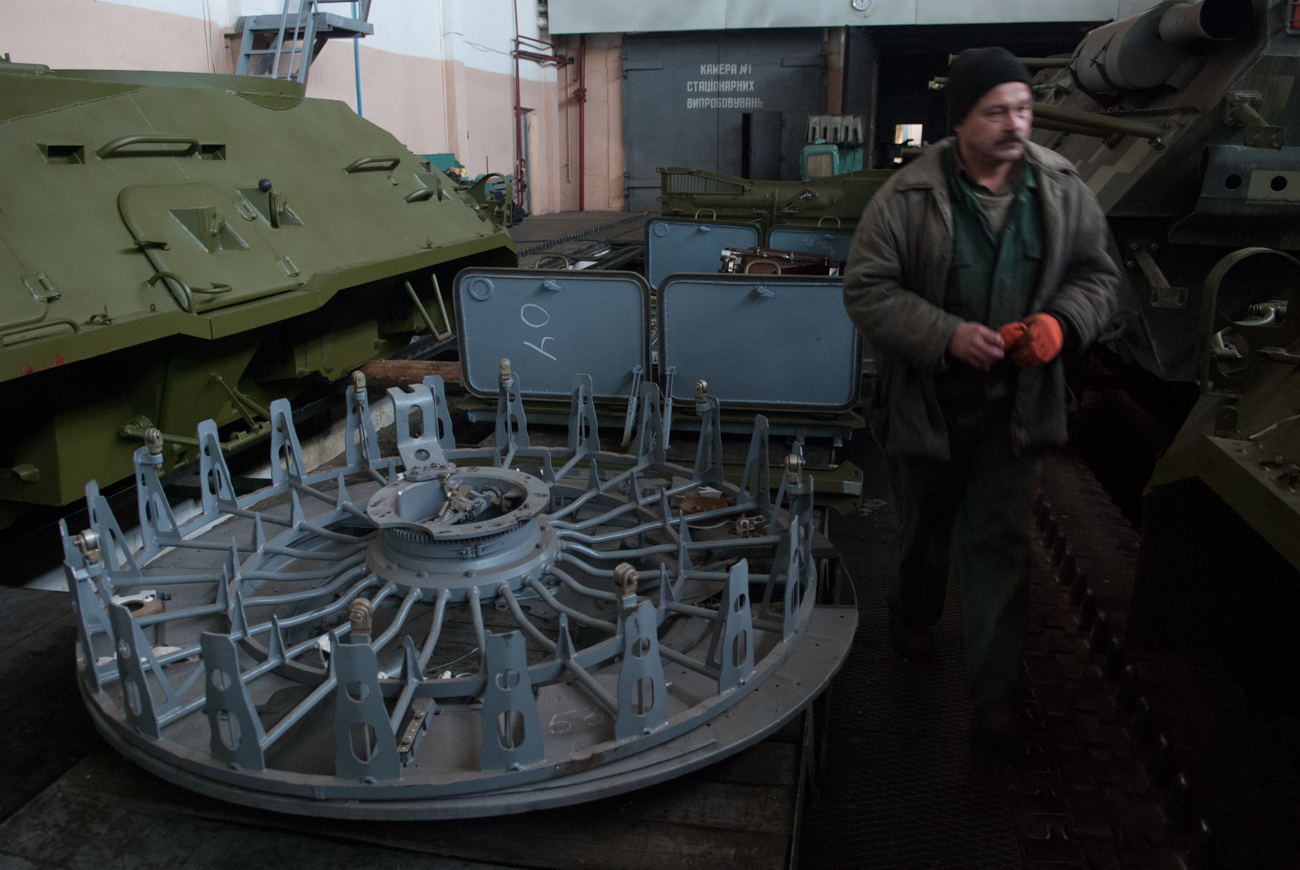

The diameter of the autoloader carousel is around 1,800mm and the height of the carousel is around 450mm. The reason for the smaller capacity of the AZ autoloader compared to the MZ series used in the T-64 and T-80 series is structural in nature; both autoloaders array the projectiles in a circle, but the AZ carousel also arrays the propellant charges. Having a larger diameter, the size of the circle that can be arranged is therefore smaller, so fewer rounds can be stowed. Because of this, the AZ autoloader has a smaller capacity despite having the same diameter as the MZ autoloader.
There is also a certain loss of volumetric efficiency as well, because both autoloaders are provisioned with a cylindrical space in the tank. With ammunition arranged in a circle, they form a multi-sided polygon, with the diameter of the ammunition being one side of the polygon. The more sides in the polygon, the closer it approximates a true circle. Having 28 cartridges, the MZ autoloader fills a cylindrical space with a 28-sided polygon, whereas the AZ autoloader fills its cylindrical space with a 22-sided polygon. The difference in volumetric efficiency is apparent from observing the fact that the gaps between the projectiles in an AZ autoloader are much larger than the gaps in an MZ autoloader.
That said, however, the MZ autoloader series is considerably less volumetrically efficient in practice due to the large swept volume occupied by the cassette raising arm suspended below the carousel. This arm is needed to raise the cassette to the ramming position behind the gun breech. As the image on the left below shows, a very large empty volume is left underneath the carousel to allow the cassette raising arm to rotate together with the cabin. For comparison, the AZ carousel (right, below) is almost directly on top of the torsion bars.
For a fighting compartment of a given volume, the AZ carousel design approach reduces the ammunition in the carousel itself, but provides a net increase in the usable volume, which is to the crew's benefit, and can be used to stow additional ammunition in reserve racks.
Inside the carousel, the cartridges are held in metal cassettes. Each cassette consists of pair of a welded steel-walled cylinders with built-in locking mechanisms to hold the ammunition firmly in place. The weight of a full cassette is 14.2 kg. The top half of the cassette is 6.9 kg and the bottom half is 7.3 kg. The cassette in the autoloader of a former NVA-operated T-72M was measured to have a wall thickness of 2.54mm. According to GOST specifications, the closest thickness to 2.54mm for steel sheets is 2.5mm, and it is likely that the true thickness of the cassette walls is 2.5mm. The additional thickness measured on the real specimen is probably the paint on top of the metal. The cassettes could be considered a surrogate to a metal case for the semi-combustible cartridges, which are otherwise more fragile to mechanical influences and fragmentation.
The maximum length of each cassette is 680mm, which is just 2mm longer than the HEAT projectiles carried by the T-72 like the BK-14 and BK-18, and only 5mm longer than HE-Frag shells like the OF-19. The APFSDS ammunition supplied to tanks during the Cold War was the shortest among the three main ammunition types, and even the 3BM-46 "Svinets" projectile fits easily into the ammo cassette.

Modified cassettes are used in the T-72B carousel in order to accommodate guided missiles. The modified cassettes have special latches on both sides accommodate guided missiles and to prevent the stabilizing fins of the missile from accidentally deploying when the missile is rammed into the cannon.

Although the new cassettes are designed to accommodate guided missiles, the length of the cassettes remain at 680mm, so the 9M119 guided missiles (695mm long) supplied to T-72B tanks will overhang the cassette by 15mm. The main factor enabling guided missiles to be carried in the autoloader carousel was not the modified cassettes, but the reduction of the diameter of the hub of the carousel. Thanks to the provisions for accommodating anti-tank missiles, APFSDS rounds of higher elongation are compatible with the AZ-184 autoloader.
The well-known author Steven J. Zaloga claims that there were some problems with zeroing the sighting system and the cannon because the sight was independently stabilized, and the vertical stabilizer for the cannon would sometimes fail to synchronize with the stabilizer unit in the sight as the cannon resets to its original position when finishing its loading cycle. However, it is doubtful if this issue truly exists, because the stabilizer for the cannon is slaved to the independently stabilized TPD-K1 sight and the fire control system features electronic fire gating via a rotary transformer on the gun trunnion, so the stabilizer will always attempt to lay the cannon as close as possible to the aiming point of the sight and permit firing only when there is coincidence between the sight and the gun within a margin of 0.5 mils. The alignment will never be perfect, because the weapons stabilizer is less precise than the stabilizer for the sight. Zaloga may have mistakenly labelled the small alignment error between the two cross-linked systems as a design flaw.
The autoloading cycle requires the gun to be locked at a pre-programmed elevation of +2°30' (+2.5 degrees) which is done so automatically as the cycle begins. During the reload cycle, a cassette is elevated to the ramming position by an electric chain-driven elevator, and the two-part ammunition is rammed into the gun breech. First the shell is loaded, and the propellant charge follows. Because the cannon automatically elevates by +3.5 degrees at the beginning of the reload cycle, the top half of the autoloader elevator is slightly tilted by the same angle to bring the cassette into alignment with the breech. The slight tilt is visible in the diagram below. The diagram shows a T-72 Ural type autoloader. The T-72B has a modified carousel, but the autoloader is otherwise identical.

The electric carousel rotation motor is shown in the cutaway drawing below. The motor is installed on top of the carousel top cover and the ZU-172 memory unit that records the position of each round stored in the autoloader (among other things) is mounted on top of the motor.

The electric motor for the ammunition cassette elevation mechanism is installed on the ceiling of the turret. The use of an electric ammunition cassette elevation mechanism instead of the hydraulic system of the MZ autoloader enables the volume of flammable hydraulic fluid located close to the ammunition to be reduced, thus indirectly increasing the survivability of the tank.
Propellant charge casing stubs are automatically ejected by a stub catcher through a small port at the rear of the turret, visible below:
The stub catcher mechanism registers the presence of a casing via a switch installed in a paddle-shaped arm located behind the stub catcher, shown in the drawing on the right. The paddle-shaped arm also keeps the stub from falling out the back of the stub catcher. When a casing stub is ejected from the cannon, it hits a pin (4) at the back of the paddle-shaped arm which lifts a conductive flat spring (5) off an electrical contact (6), breaking the circuit and prompting the system to register the presence of a propellant charge casing stub in the stub catcher mechanism.

When the gunner activates the autoloader to load the cannon, the stub catcher mechanism is lifted to the ejection port in the turret roof by a linear actuator installed underneath the breech housing of the gun, and the stub is ejected by a pair of ejector levers, powered by a torsion bar. As the ejector mechanism is lowered back into its position behind the breech, the torsion bar for the ejectors is rewound. The paddle-shaped arm is swung away to the side (in the direction of the gunner) by the ammunition cassette elevator to make way for the ramming mechanism.

When loading the cannon manually in the total absence of electrical power, the spent casing stub held in the stub catcher mechanism is removed by manually pulling the paddle-shaped arm away. After that, the casing stub can just be pushed out the back of the stub catcher and thrown away or stowed away somewhere in the tank. The spent casing stub shold be removed after every shot when firing the gun manually. If not, the casing stub from the next shot would hit the previous stub and fall down onto the carousel cover. Firing without removing the case stub is permissible in emergencies but should be avoided. The photo below shows a case stub being removed manually.
Unlike what most people assume, it is completely possible to unload the cannon after a shot is already loaded. Although not always necessary, this may be useful when two different threats appear one after another. For instance, enemy infantry may appear after the T-72 has finished dealing with an enemy tank, so switching to HE-Frag will be necessary. If an APFSDS round is still loaded in the cannon, it will have to be unloaded either by returning it to the autoloader or firing it off, perhaps into the previously knocked-out enemy tank to ensure that it is truly disabled. If it is desirable to conserve APFSDS ammunition, then the loaded round should be unloaded from the back end of the cannon rather than the front. This can be done by simply using the commander's autoloader control box. The empty ammunition cassette is raised from the carousel, whereby the commander can open the breech manually using the breech operating handle. The ejection of the propellant charge is done automatically by an ejector built into the cannon. The action of pulling the breech operating handle opens the breech and returning the breech operating handle to its stowed position manually activates the ejector to push the propellant charge out of the chamber. The chambered projectile is not ejected; it must be extracted by hand. The propellant charge and projectile are inserted into the empty cassette and returned to the autoloader carousel. After this, the gunner can continue the target engagement process as normal. The amount of time needed to complete this operation is non-trivial, but it is absolutely possible if the situation calls for it.
MEMORY UNIT

The autoloader is able to recognize the position of each round stored in the carousel using the carousel storage memory unit, as shown below (ZU-172 model for the AZ-172 autoloader). Three ammunition types can be indexed into the carousel in this model. This device is mounted next to the trapdoor of the carousel cover, at a position where the commander can access it easily when replenishing the carousel.

The memory unit indexes the type of ammunition on a data disc stored inside the circular housing. The type of ammunition is identified using a binary system on the data disc. There are four magnetic rings on the surface of the disc. The rings are divided into a total of twenty two groups; one group for each round stowed in the autoloader carousel. Each group consists of three sets of four ring sectors. In each group, four of the sectors are for recording the type of ammunition (ammo set), four are used to determine when to brake the carousel rotation motor (braking set), and four are used to determine where to stop the carousel in order to line up the ammunition to the trapdoor (stopping set). Each sector stores one bit of data. As there are twenty two groups with twelve data recording elements capable of storing one bit each, the data disc is considered to have a storage capacity of 264 bits.

Within each group, the sectors are divided into the following sets:
ПК3, ПК6, ПК9, ПК12 - to record ammunition type
ПК2, ПК5, ПК8, ПК11 - to initiate braking
ПК1, ПК4, ПК7, ПК10 - to stop the carousel
The ammunition recording set will record one ammunition type in each sector.
ПК3 - EmptyПК6 - HE-Frag
ПК9 - APFSDSПК12 - HEAT
As the data reader contacts turn around the fixed disc, the first set that will be read by the system is the ammunition type record set. Then, as the carousel continues to spin, the reader contacts will run over the braking set, causing the carousel rotation motor to begin braking. Once the reader contacts reach the stopping set, the motor brakes the carousel hard to fix it in place, positioning it on the cassette elevator. If the ammunition type read by the system does not correspond to the type chosen by the gunner on his selector dial, the braking and stopping sets are ignored.
When the autoloader loading cycle is activated by the gunner, the carousel motor receives the command to rotate, but it does not know when to stop until the memory unit reaches the appropriate ammunition type, so if the gunner selects HEAT rounds, the carousel will rotate until the system reads the appropriate binary code on the data disc whereupon the command to brake and stop the carousel motor is read and processed by the autoloader.
In other words, the system does not know what the shortest route to the selected ammunition type is. This system limits the carousel to rotating in only one direction even though the motor is actually capable of rotating in both directions. Due to the system limitations, the reverse rotation is only activated when braking the rotation of the carousel. This is unlike the MZ autoloader of the T-64A and T-80 which has an autoloader memory system that is able to dynamically read the positions of all ammunition stored inside the carousel and display it digitally on a special circular device. However, the MZ autoloader is also not capable of rotating in both directions. Instead, the MZ autoloader has a "sequence" loading mode where the carousel will automatically spin to the next round of the type selected by the gunner immediately after loading.
After the round is loaded and the ammo cassette returns to the carousel, the memory unit instantaneously rewrites the data to a zero value to represent the empty status of the cassette so that the autoloader will ignore empty cassettes when loading. Conversely, the system is reversed when the autoloader is set to the replenishment mode, so that the carousel will only stop at empty cassettes when replenishing the carousel, ignoring filled cassettes.
When replenishing the carousel, recording the ammunition information is done by three current carrying pins connected to the magnetic rings via electrical contacts. Data storage is done by changing the polarity of the sector groups to either positive or negative using the electrical contacts. The electrical contacts are spring loaded to keep them in contact with the magnetic rings to ensure that reading and writing the data is still possible even while the device is experiencing strong vibrations such as when the tank is on the move over rough ground or after the tank is hit with the shockwave of an explosive blast. However, the constant pressure wears out both the magnetic ring and the electrical contact over time as the contacts rotate over the disc, leading to a loss in the ability to record and read data, and the conductive metallic dust produced by the rubbing of the contact on the ring surfaces can contaminate other parts of the unit, causing reading errors. Such errors could prevent the autoloader from accepting new ammunition when loading it, or cause the autoloader to lose track of where ammunition is stored or even to "forget" when to stop rotating the carousel if it is already in motion, so that it rotates indefinitely. Even if the recording surfaces are not worn out, it is also possible for the device to fail from the accumulation of dust and grime over time. At this point, it is possible to either replace the electrical contacts on the hard disc, or replace the entire memory unit. This is an easy task that can be done in the field as long as a spare memory unit is available, as the replacement of the unit only requires that the old one has its electrical cable unplugged.
The rotation of the reader contacts around the fixed data disc is not powered by an internal motor, but rather, is driven by the carousel rotation motor via a gearbox leading to shaft passing through the bottom of the memory unit.
The design of the data disc is clearly an extremely simple and archaic form of hard disc storage with an extremely low storage capacity. The lack of sophistication, however, is completely justified by the lack of a need to store a large volume of data and the high robustness required of the system. The simple design of the memory unit grants high resistance to shock and mechanical damage, and its self contained housing facilitates quick replacement if it is damaged. Apparently, one of the most common source of autoloader malfunctions is the memory unit.
Due to the limit of three ammunition types, this memory unit is not used in the T-72B, as there is a new type of ammunition: guided missiles. According to the patent for the T-72B autoloader (Russian Patent No. 2204776), the memory storage was upgraded to accept a fourth ammunition type; missiles. The upgraded memory storage unit was also improved for better reliability.

To record a fourth ammunition type, the data disc features five magnetic rings instead of four. The first sector in the ammo set records an empty cassette, while the other four record ATGM, APFSDS, HEAT and HE-Frag. The storage capacity increased to 330 bits. Additionally, this new memory storage unit features a new input mechanism with a rotary dial instead of three buttons. The method of reading and recording data is functionally the same, differing only in how the mechanism functions. The dial has four positions for the four ammunition types. To select and index an ammunition type, the dial is turned to one of the four positions, and then pressed. The position of the dial serves to position a mechanical stop, to limit how far the writer contact can travel along the disc. When the dial is pressed, a servomotor is activated to move the writer contact until it hits the stop, and then a current passes through the writer contact. Whichever sector the contact is laid upon will be energized. In this way, one of the five sectors will be switched to a one value while the others remain with a zero value, thus recording one ammunition type.


A closer look at the dial is available in this video at (3:08). The new memory unit can be seen in the screenshot below.

The photo below shows a T-72 Ural or T-72A, as evidenced by the welded appliqué armour plate on the upper glacis. Note the T-shaped power distribution unit at the center of the hull where the carousel would be fitted.

The model of the unit is the VKU-330-4, as shown below.

The permissible length of projectiles in the T-72B autoloader carousel was increased by reducing the size of the central hub. This was done by redesigning the hub which was accompanied by a switch from the VKU-330-4 power distribution unit to the VKU-1 unit. The photo below shows a T-72B3 with a VKU-1. Note the three protruding arms instead of a T-shape.

This modification enabled the 695mm-long 9M119 guided missile to be used with the autoloader carousel. The T-72B1 uses the AZ-172 autoloader and memory system since it is a low cost version of the T-72B without the missile firing capability, so the upgraded autoloader is not necessary.
In the T-90A autoloader, the system was revised and digitized. The information on the type and location of the ammunition in the carousel is stored digitally in a separate device, and the shortest distance to reach the ammunition is determined by an algorithm. The absence of the old disc-type memory unit is confirmed in the photo below, although the crankshaft housing from the carousel that would have rotated the hard disc is still present as a "vestigial tail" of sorts. This is evidence that although the control system was overhauled, the T-72B carousel was retained. The issue of two-way rotation is resolved by the implementation of a sufficiently sophisticated control system. The carousel rotation motor itself is reversible and has always been capable of both clockwise and anti-clockwise rotation since the original version in the T-72 Ural, but due to the rather crude ammunition retrieval system, the reverse function of the motor had only been used for braking until then.

There are some claims that the T-72B3 uses the autoloader from the T-90A, and that this allows the T-72B3 to use more elongated APFSDS rounds. Currently available evidence shows that this is not the complete truth. A T-72B3 with the old T-72B memory unit (Red) and commander's control box (Yellow) can be see in the photo below.

This shows that the ammunition indexing and retrieval system is still based on the older T-72B, so the carousel must also be from the T-72B. However, it is clear that the system has been revised. Note that the old ammunition selector dial has been replaced with a new one. The photo below - this time showing the T-72B memory unit (Red) in a T-72B3 obr. 2016 - supports this theory. Even in 2016, the T-72B3 is evidently still using the old T-72B carousel, and even the same control box (Yellow) is used.

The T-72B3 obr. 2016 is indeed modified to accept longer APFSDS rounds. More specifically, it is designed to accommodate Svinets-1 and Svinets-2. This is according to a saved copy of order document No. 31603190542 by Uralvagonzavod corporation in a government registry of purchase documentation which contains two mentions of modernizing the autoloader to enable the use of products designated as "S-1" and "S-2".
One similarity between the T-72B3 and the T-90 autoloaders is in the sequence of actions of the stub ejection port hatch which is observed to momentarily open and close immediately after firing without actually ejecting a shell casing stub, presumably to evacuate the fumes. This feature was first seen in the T-90 as displayed in this video, this video and this video and many others. The fact that the T-72B3 also has this feature indicates that it shares something in common with the T-90 autoloader. As we have seen, there is evidence to show that the T-72B autoloader can load longer projectiles than the Ural autoloader, but there is nothing concrete that indicates that there were any further upgrades to projectile length after the T-72B. It is often assumed that the carousel is to blame for the limited projectile length, there is evidence that other factors are to blame for this limitation.
In June 2005, a patent (Patent No. 2300722) filed by UKBTM for a method of increasing the permissible length of projectiles usable in the autoloader was filed. The patent describes a modified autoloader elevator design wherein the ammo cassette is pulled backward to avoid the cannon breech as it is elevated to the ramming position. It is hinted in the patent that the main restriction on the projectile length is not the carousel, but the cannon. To be more specific, the patent states that a possible method of increasing the permissible length of projectiles involves moving the cannon forward, and that this would require significant reworking of the turret, and it would disrupt the balancing of the cannon. The carousel is not mentioned at all. It is not clear if this patented system was actually implemented in new production tanks or implemented at all, but since the carousel is not the main limiting factor, it is absolutely possible that the T-72B3 can simultaneously have the old T-72B carousel installed and still be able to fire the same shells as the T-90A.
The photo below shows the location of the memory unit for the T-72 Ural and the carousel trapdoor through which the two-piece ammunition passes through. The drawings on the right show the carousel itself and the carousel frame.

This scan comes from the book "T-72/72M/72M1 in detail", from preview pictures available on super-hobby.com (link).
The time taken per shot is around 7 seconds. This enables the tank to achieve a maximum rate of fire of 7 to 8 rounds per minute. The cyclogram below shows the chronological order of the steps in the autoloading process.

The cyclogram gives a total loading time of around 7.7 seconds, but this is because the cyclogram includes the rotation of the carousel over two ammunition cassettes instead of transferring directly to the next one to represent a specific ordered arrangement of ammunition in the carousel or to represent a the time taken when switching ammunition types. The cyclogram also includes the firing and recoil of the cannon after the loading cycle, so the total time taken represents the time taken between shots rather than the time taken by a reload cycle. With a time between shots of 7.7 seconds, the AZ autoloader is on par with the MZ autoloader which achieves a speed of 7.5 seconds under the same circumstances (loading the third round in the sequence). The difference of 0.2 seconds is simply imperceptible.
As you can see in the cyclogram, the last second of the loading cycle is taken up by the release of the cannon from hydrolock and by the automatic laying of the cannon back into the last previous aiming position and then onto the new aiming point, so the gunner can open fire immediately, which is represented by the tag "Recoil of the cannon" that represents the firing of the cannon immediately after loading is concluded. This is possible because of the independent vertical stabilization of the gunner's primary sight and the separation of the turret traverse system from the rotation system of the autoloader carousel, so he can conduct ranging and aim at a new target during the loading cycle. This is no different from any other modern fire control system. The biggest drawback of the AZ autoloader is that it requires two ramming cycles instead of ramming the entire two-part cartridge in one go, like the MZ autoloader of the T-64.
The AZ autoloader carousel is very compact, as you can see in the photo below. Based on this official UKBTM drawing of the cross-section of a T-72, the carousel occupies around half of the internal height of the hull, so its height is around 450mm, including the top cover. Excluding the top cover, the carousel has a height equivalent to a standing propellant charge (408mm), including the struts that mount the carousel to the belly of the tank. Note that the carousel in the photo below has a cylinder attached to the central hub, indicating that this carousel is for a T-72B.

There is some additional equipment installed on top of the carousel cover. The silver box you see near the center of the carousel cover is a KR-175 relay box. It connects to the VKU-330-4 power distribution unit and supplies power to the turret.


The T-72 does not have a significant disadvantage when compared to human loaded counterparts, which include the majority of NATO tanks. Most examples can achieve a 4 to 5 second loading time - when their tank is immobile. However, it's a whole different story on rough terrain. An
advantage to the autoloader is that a bumpy ride, change of direction
or slope traversal will never affect the autoloader's
operation in any way. It can maintain its normal cyclic loading rate in
whatever
condition or orientation the tank is in. In manually-loaded tanks, the whole vehicle will pitch and dive as it drives over ruts and mounds while the gun - which would be disconnected from the stabilization system in tanks like the Abrams when the loader drops the safety lever - will move up and down on its own volition, making it less straightforward for the loader to get the shell aligned with the chamber to ram it in.
Firing on the move is usually done at a low cruising speed or at a crawl in order to maximize accuracy, but a tank speeds up and performs evasive maneuvers in between shots in order to avoid enemy fire, before slowing down again to return fire. The stressful time between shots is when the loader must perform his duties, and it would generally be harder to load the cannon during that time. This video illustrates this point perfectly. At 1:08 and 1:31 in the video, the movement of the gun delays the loader by around a second, extending his loading time to 7.9 seconds and 8.2 seconds respectively (loading time is defined as the time between dropping the loader's safety lever and moving back to a position away from the path of recoil). This would not be an issue for a tank furnished with an autoloader, but to be fair, this is also not an issue for tanks installed with a loader's assist system where the gun automatically raises by a few degrees and fixes the breech in detente, placing it at the optimum loading angle for the loader. The earliest tank to have this feature was the T-54B, followed by the T-62. Later on, tanks like the Leopard 2 and the Merkava 4 featured similar loader's assist systems.
The autoloader can maintain its cyclic loading speed throughout an extended engagement until the carousel is exhausted. On the other hand, the speed of a human loader is affected by the location of the ammunition and the orientation of the turret as well as the motion of the tank. For example, a Leopard 2 tank stows only fifteen rounds in the ammunition compartment in its turret bustle, but only six rounds are available to the loader at any time due to the small size of the blast door and the design of the collapsible ammunition racks, so he must manually rearrange the racks after the six rounds are expended. He cannot do this in between shots because the blast door must remain closed until the loader opens it to load the cannon or the purpose of the compartmentalized ammunition would be completely defeated. Furthermore, a human loader may become fatigued long before the ammunition is exhausted or even before combat even commences, whether it be due to excessive heat, excessive cold, shortage of food, shortage of water, or any other imaginable fact of life for a soldier fighting on the front lines. For instance, it was mentioned earlier in this article the personnel heater in the M60A1 and M60A3 was astonishingly unreliable and frequently caused the fire extinguisher system to discharge accidentally, and some tanks like the Chieftain did not have a heater at all. The efficiency of a human loader would be affected by this, whereas an autoloader would not.
All in all, the T-72's autoloader is entirely satisfactory for generating a sustainable rate of fire for realistic encounters.
The overhead cover on top of the carousel acts as a false floor for the occupants in the turret. The entire carousel with all attached equipment weighs 460.1 kg, but the carousel with the cover alone (excluding the ammunition trays) weighs 293.72 kg, while the cover itself weighs 130.8 kg.
The autoloader carousel cover itself is a welded structure built from 2.54mm (0.1") steel plates. The sheet steel cover is bent down at the edges for structural stiffness. Additionally, the sheet steel guard behind the driver's station has a thickness of 3.1mm (0.123"). The closest thicknesses for sheet steel in GOST specifications is 2.5mm and 3.0mm respectively, so any additional thickness can be attributed to the paint on top of the metal.


The carousel rotates independently of the turret. It can rotate to line up new shells at a nominal speed of 70 degrees per second, but as mentioned before, it can only rotate in a counterclockwise direction. This needlessly prolonged the loading cycle in some circumstances, but it is entirely possible to avoid this issue by practicing smart ammo placement. If APFSDS ammunition is stowed to the right of HEAT ammunition, and HEAT ammunition is stowed to the right of HE-Frag ammunition, the time needed to load anti-armour rounds can be greatly reduced at the expense of greatly increasing the time taken to reach the HE-Frag rounds. This way, the gunner can start with APFSDS, and then switch to HEAT without delay when APFSDS is exhausted, or switch to HEAT quickly to deal with IFVs when the high priority tank targets have already been knocked out. Switching to HE-Frag from APFSDS takes longer, but if the target is supposed to be engaged with HE-Frag, then it can be assumed that it is a lower priority threat. In general, sorting the ammunition this way is simply logical, as the time taken to switch ammunition types only increases when switching to ammunition designed for less dangerous threats. In this case, the hierarchy of danger would be: Tank, IFV, and Infantry or other.
One of the techniques developed by a T-64A tank company commander during the 1970's was to load the ammunition in repeating sets of alternating groups so that the time needed for the carousel to reach each round would be equal, and that less time would be spent switching ammunition types. For example:
APFSDS - HEAT - HE-Frag - APFSDS - HEAT - HE-Frag - APFSDS - HEAT - HE-Frag
By doing this, switching from APFSDS to HEAT would take less time than loading the next APFSDS round. This solved the problem of increased loading time when switching ammunition types, but created the additional problem of increasing the time needed to load ammunition of the same type. However, this was considered an acceptable compromise due to the slow carousel rotation speed of the MZ autoloader of the T-64 and T-80 - only 26 degrees per second. It would take an unbearably long time to scroll through large parts of the carousel simply to reach the desired ammunition type. This technique became institutionalized and was a typical method of sorting ammunition among tankers. However, it is not known if T-72 tankers were taught this technique, as it would not have been very useful. The carousel of the AZ autoloader spins almost three times faster than the MZ autoloader, so this problem is much less serious and the flaws of this sorting technique become rather more pronounced. For one, neither the T-64 or the T-72 carry an equal distribution of all three ammunition types, especially not when missiles became a part of their repertoire.
For instance, the standard combat load of a East German T-72M (according to an ex-GDR tank commander) would have 9 APFSDS rounds, 2 HEAT rounds and 11 HE-Frag rounds in the autoloader carousel. It is not possible to arrange these rounds in such a way that the three ammunition types alternate in repeating sets, and it would not be desirable to do so. When engaging tanks, it is much quicker to have the APFSDS rounds grouped together so that the next round is loaded as quickly as possible, allowing the gunner to rapidly fire a potentially decisive second shot. Arranging the ammunition in alternating groups takes away this capability.
Here is a video of a demonstrator autoloader carousel spinning:
In the summer of 1969, a comprehensive test cycle conducted on a number of Object 172 tanks in Central Asia and in the South-Western regions of Russia revealed that the air purification system, engine cooling system, the autoloader and the T-64 suspension had insufficient reliability. These issues were partially eliminated on the subsequent batch of Object 172 tanks. Work on these tanks continued until February 1971, and by then, most of the subsystems in the tank were working within acceptable parameters. The reliability of the Object 172 autoloader at that point was excellent, having a loading failure rate of only 1 per 448 loading cycles where one loading cycle was defined as loading one round of ammunition into the autoloader or the autoloader loading one round into the cannon. Some improvement in the autoloader can be expected since the testing of the Object 172 prototype in February 1971, so the MTBF (Mean Time Before Failure) of the autoloader is likely to be above 448 rounds for a production model T-72 (Object 172M) and probably improved with time.

The photo below shows a T-72 Ural or T-72A, as evidenced by the welded appliqué armour plate on the upper glacis. Note the T-shaped power distribution unit at the center of the hull where the carousel would be fitted.

The model of the unit is the VKU-330-4, as shown below.
The permissible length of projectiles in the T-72B autoloader carousel was increased by reducing the size of the central hub. This was done by redesigning the hub which was accompanied by a switch from the VKU-330-4 power distribution unit to the VKU-1 unit. The photo below shows a T-72B3 with a VKU-1. Note the three protruding arms instead of a T-shape.

This modification enabled the 695mm-long 9M119 guided missile to be used with the autoloader carousel. The T-72B1 uses the AZ-172 autoloader and memory system since it is a low cost version of the T-72B without the missile firing capability, so the upgraded autoloader is not necessary.
In the T-90A autoloader, the system was revised and digitized. The information on the type and location of the ammunition in the carousel is stored digitally in a separate device, and the shortest distance to reach the ammunition is determined by an algorithm. The absence of the old disc-type memory unit is confirmed in the photo below, although the crankshaft housing from the carousel that would have rotated the hard disc is still present as a "vestigial tail" of sorts. This is evidence that although the control system was overhauled, the T-72B carousel was retained. The issue of two-way rotation is resolved by the implementation of a sufficiently sophisticated control system. The carousel rotation motor itself is reversible and has always been capable of both clockwise and anti-clockwise rotation since the original version in the T-72 Ural, but due to the rather crude ammunition retrieval system, the reverse function of the motor had only been used for braking until then.

There are some claims that the T-72B3 uses the autoloader from the T-90A, and that this allows the T-72B3 to use more elongated APFSDS rounds. Currently available evidence shows that this is not the complete truth. A T-72B3 with the old T-72B memory unit (Red) and commander's control box (Yellow) can be see in the photo below.

This shows that the ammunition indexing and retrieval system is still based on the older T-72B, so the carousel must also be from the T-72B. However, it is clear that the system has been revised. Note that the old ammunition selector dial has been replaced with a new one. The photo below - this time showing the T-72B memory unit (Red) in a T-72B3 obr. 2016 - supports this theory. Even in 2016, the T-72B3 is evidently still using the old T-72B carousel, and even the same control box (Yellow) is used.

The T-72B3 obr. 2016 is indeed modified to accept longer APFSDS rounds. More specifically, it is designed to accommodate Svinets-1 and Svinets-2. This is according to a saved copy of order document No. 31603190542 by Uralvagonzavod corporation in a government registry of purchase documentation which contains two mentions of modernizing the autoloader to enable the use of products designated as "S-1" and "S-2".
One similarity between the T-72B3 and the T-90 autoloaders is in the sequence of actions of the stub ejection port hatch which is observed to momentarily open and close immediately after firing without actually ejecting a shell casing stub, presumably to evacuate the fumes. This feature was first seen in the T-90 as displayed in this video, this video and this video and many others. The fact that the T-72B3 also has this feature indicates that it shares something in common with the T-90 autoloader. As we have seen, there is evidence to show that the T-72B autoloader can load longer projectiles than the Ural autoloader, but there is nothing concrete that indicates that there were any further upgrades to projectile length after the T-72B. It is often assumed that the carousel is to blame for the limited projectile length, there is evidence that other factors are to blame for this limitation.
In June 2005, a patent (Patent No. 2300722) filed by UKBTM for a method of increasing the permissible length of projectiles usable in the autoloader was filed. The patent describes a modified autoloader elevator design wherein the ammo cassette is pulled backward to avoid the cannon breech as it is elevated to the ramming position. It is hinted in the patent that the main restriction on the projectile length is not the carousel, but the cannon. To be more specific, the patent states that a possible method of increasing the permissible length of projectiles involves moving the cannon forward, and that this would require significant reworking of the turret, and it would disrupt the balancing of the cannon. The carousel is not mentioned at all. It is not clear if this patented system was actually implemented in new production tanks or implemented at all, but since the carousel is not the main limiting factor, it is absolutely possible that the T-72B3 can simultaneously have the old T-72B carousel installed and still be able to fire the same shells as the T-90A.
The photo below shows the location of the memory unit for the T-72 Ural and the carousel trapdoor through which the two-piece ammunition passes through. The drawings on the right show the carousel itself and the carousel frame.
This scan comes from the book "T-72/72M/72M1 in detail", from preview pictures available on super-hobby.com (link).
The time taken per shot is around 7 seconds. This enables the tank to achieve a maximum rate of fire of 7 to 8 rounds per minute. The cyclogram below shows the chronological order of the steps in the autoloading process.
The cyclogram gives a total loading time of around 7.7 seconds, but this is because the cyclogram includes the rotation of the carousel over two ammunition cassettes instead of transferring directly to the next one to represent a specific ordered arrangement of ammunition in the carousel or to represent a the time taken when switching ammunition types. The cyclogram also includes the firing and recoil of the cannon after the loading cycle, so the total time taken represents the time taken between shots rather than the time taken by a reload cycle. With a time between shots of 7.7 seconds, the AZ autoloader is on par with the MZ autoloader which achieves a speed of 7.5 seconds under the same circumstances (loading the third round in the sequence). The difference of 0.2 seconds is simply imperceptible.
As you can see in the cyclogram, the last second of the loading cycle is taken up by the release of the cannon from hydrolock and by the automatic laying of the cannon back into the last previous aiming position and then onto the new aiming point, so the gunner can open fire immediately, which is represented by the tag "Recoil of the cannon" that represents the firing of the cannon immediately after loading is concluded. This is possible because of the independent vertical stabilization of the gunner's primary sight and the separation of the turret traverse system from the rotation system of the autoloader carousel, so he can conduct ranging and aim at a new target during the loading cycle. This is no different from any other modern fire control system. The biggest drawback of the AZ autoloader is that it requires two ramming cycles instead of ramming the entire two-part cartridge in one go, like the MZ autoloader of the T-64.
The AZ autoloader carousel is very compact, as you can see in the photo below. Based on this official UKBTM drawing of the cross-section of a T-72, the carousel occupies around half of the internal height of the hull, so its height is around 450mm, including the top cover. Excluding the top cover, the carousel has a height equivalent to a standing propellant charge (408mm), including the struts that mount the carousel to the belly of the tank. Note that the carousel in the photo below has a cylinder attached to the central hub, indicating that this carousel is for a T-72B.

There is some additional equipment installed on top of the carousel cover. The silver box you see near the center of the carousel cover is a KR-175 relay box. It connects to the VKU-330-4 power distribution unit and supplies power to the turret.

Firing on the move is usually done at a low cruising speed or at a crawl in order to maximize accuracy, but a tank speeds up and performs evasive maneuvers in between shots in order to avoid enemy fire, before slowing down again to return fire. The stressful time between shots is when the loader must perform his duties, and it would generally be harder to load the cannon during that time. This video illustrates this point perfectly. At 1:08 and 1:31 in the video, the movement of the gun delays the loader by around a second, extending his loading time to 7.9 seconds and 8.2 seconds respectively (loading time is defined as the time between dropping the loader's safety lever and moving back to a position away from the path of recoil). This would not be an issue for a tank furnished with an autoloader, but to be fair, this is also not an issue for tanks installed with a loader's assist system where the gun automatically raises by a few degrees and fixes the breech in detente, placing it at the optimum loading angle for the loader. The earliest tank to have this feature was the T-54B, followed by the T-62. Later on, tanks like the Leopard 2 and the Merkava 4 featured similar loader's assist systems.
The autoloader can maintain its cyclic loading speed throughout an extended engagement until the carousel is exhausted. On the other hand, the speed of a human loader is affected by the location of the ammunition and the orientation of the turret as well as the motion of the tank. For example, a Leopard 2 tank stows only fifteen rounds in the ammunition compartment in its turret bustle, but only six rounds are available to the loader at any time due to the small size of the blast door and the design of the collapsible ammunition racks, so he must manually rearrange the racks after the six rounds are expended. He cannot do this in between shots because the blast door must remain closed until the loader opens it to load the cannon or the purpose of the compartmentalized ammunition would be completely defeated. Furthermore, a human loader may become fatigued long before the ammunition is exhausted or even before combat even commences, whether it be due to excessive heat, excessive cold, shortage of food, shortage of water, or any other imaginable fact of life for a soldier fighting on the front lines. For instance, it was mentioned earlier in this article the personnel heater in the M60A1 and M60A3 was astonishingly unreliable and frequently caused the fire extinguisher system to discharge accidentally, and some tanks like the Chieftain did not have a heater at all. The efficiency of a human loader would be affected by this, whereas an autoloader would not.
All in all, the T-72's autoloader is entirely satisfactory for generating a sustainable rate of fire for realistic encounters.
CAROUSEL PROTECTION
The overhead cover on top of the carousel acts as a false floor for the occupants in the turret. The entire carousel with all attached equipment weighs 460.1 kg, but the carousel with the cover alone (excluding the ammunition trays) weighs 293.72 kg, while the cover itself weighs 130.8 kg.
The autoloader carousel cover itself is a welded structure built from 2.54mm (0.1") steel plates. The sheet steel cover is bent down at the edges for structural stiffness. Additionally, the sheet steel guard behind the driver's station has a thickness of 3.1mm (0.123"). The closest thicknesses for sheet steel in GOST specifications is 2.5mm and 3.0mm respectively, so any additional thickness can be attributed to the paint on top of the metal.


The cover is additionally covered in up to two layers of "Podboi" anti-radiation lining with a thickness of around 13mm each. "Podboi" is known to be an effective spall liner, so it serves as additional protection for the ammunition inside the carousel. The anti-radiation lining carried over from the T-72 Ural to the T-72A, T-72B and the T-72B3, but was removed in the T-90 and compensated by thickening the cover. Most zones of the carousel cover have two layers of the lining, so that the thickness is more than 13mm in the majority of zones, up to a total of 26mm. This not only gives the turret occupants a layer of security from penetrating radiation entering the tank from below via irradiated soil, but also improves the protection of the ammunition inside the carousel.

Outside of the small sector behind the driver's seat, the perimeter of the carousel intersects with either the hull walls or the conformal fuel tanks. The thickness of the guards was increased for the T-72B autoloader. One of the original perimeter guards can be seen in the photo below (open image in new tab and zoom in). Note the two reinforcement ribs pressed in to the plate - this indicates that the plate is quite thin and flimsy.
This photo gives us a closer look at the guard. The sheet is quite thin - only a few milimeters thick - so it is more likely that its main function is to help prevent unintentional interactions between the driver and the carousel and not to protect the ammunition from spall and fragmentation, although it is worth noting that the guard fully covers the ammunition. A small gap exists between the carousel cover and the guard, but nothing of importance is behind it.

The sheet steel guard can also be seen on the left of the picture below. Screenshot taken from TV Zvezda series "Made In the USSR", episode "T-72 Main Battle Tank".

In the T-72B, these ribbed steel guards were replaced with thicker solid aluminium plates, as seen in the photo below of a late model T-72B undergoing repairs at the 103rd Armoured Repair Plant in the Far East (photo credit to darkbear-ru). The upgrade to the new aluminium plating began in April 1986. It is very unlikely that the tank in the photos below is a T-72B3 model because the delivery of the very first T-72B3 tanks only began in 2013, whereas the photos below were uploaded to darkbear-ru's livejournal in December 2012. Also, the tank has clearly seen some use as shown by the worn rubber rims of the roadwheels.

The locations of the armoured guards around the perimeter of the carousel did not change. One plate is located between the driver and the autoloader carousel and another plate is located between the air supply unit and the autoloader carousel. Thus, the carousel is protected in the 10 o'clock to 12 o'clock sector and in the 4 o'clock sector. The front right hull fuel tanks offer protection in the 1 o'clock sector and the rear conformal fuel tank offers protection in the 5 o'clock to 8 o'clock sector. The remainder is unprotected, as there is no equipment between the carousel and the sides of the hull.
The lower left corner of the screenshot below grants us a closer look at the guards for the T-72B3 carousel. It appears that the aluminium guard plate was not changed from the T-72B to the T-72B3.
The T-90A appears to have the same aluminium guards as the T-72B and T-72B3 as well as additional guards on the sides of the carousel. The sector of the armoured guard directly behind the driver is shown in the photo on the left below (credit to twower). Note that there are two fire extinguisher canisters clipped to the guard plate. The same clips are seen in both of the photos of the T-72B and T-72B3, likely indicating that all three tanks have the same plate installed in front of the carousel, but it is less clear if the additional guards for the sides of the carousel were fitted to any T-72B model. The rather large gap seen in the photo below is only due to the top-down perspective of the photographer. When viewed horizontally, the armoured plate almost fully covers the side of the carousel.


As T-72B1 uses the autoloader of the T-72 Ural, it also retains the old type of thin sheet steel guard rather than the aluminium guard.
The type of steel used for the perimeter guards are not known, but the thickness of the older T-72 Ural-style sheet steel guards would be insufficient for real ballistic protection. The thicker aluminium plate in the T-72B can be considered to be more serious protection against spall and fragments, and would probably have a positive effect on the survivability of the tank under some circumstances. The thickness of the aluminium guard plate is likely to be around one centimeter, so that the weight is the same as the original sheet steel guard. It is important to point out that it is known that the original guards are made from steel and not aluminium because rust is observed on the surface of the sheets, whereas the new thick guard is known to be aluminium because of oxidation.
This article translated by Peter Samsonov details the post-penetration effects of 125mm APFSDS ammunition. The original pages of the Russian document were first shared on Andrei Tarasenko's blog. The document featured in the article pertains to a lethality analysis done on 3BM9, 3BM15, 3BM22 and 3BM26. These four rounds will all be examined more closely later on, but for now, it is only necessary to summarize that the 3BM-9 is an all-steel "torpedo" projectile, while the 3BM15 and 3BM-22 are composite shells with a a tungsten carbide core at the front of the projectile, and the 3BM26 has a tungsten carbide core in its tail. All of the shots were for a 60 degree obliquity impact, and the velocity of all of the shells corresponds to their velocities at 2 km.
According to the article, the vast majority of fragments expelled behind the armour plate are smaller particles that are capable of penetrating 3-6mm of aluminium sheet at a distance of 0.5 to 1 meters. Although they do not seem powerful, these particles are far from harmless. Particles with the ability to penetrate more than 3mm of aluminium include particles with a mass of 2 to 50 grams and a velocity of 300 to 1,700 m/s. To gain an appreciation of the threat posed by such particles, note that a typical .22LR bullet weighs 2.33 grams and travels at 390 m/s and a 5.56mm M193 Ball bullet weighs 3.56 grams and travels at 990 m/s. As such, each particle that was found to be able to penetrate 3-6mm of aluminium would also be capable of causing lethal wounds.
Keeping in mind that the overmatch factor used in the experiments was in the range of 100mm to 300mm, these figures simply cannot be considered realistic if the same or equivalent ammunition was fired at a T-72 tank, but assuming that a composite shell managed to overmatch the front hull armour of the T-72B by 100mm to 300mm, most of the fragments will definitely not be able to penetrate the steel guard around the perimeter of the carousel, especially not after passing through the anti-radiation lining (which doubles as a spall liner) lining the interior walls of the tank. This is important, because igniting or detonating ammunition requires a certain amount of energy. Very low energy fragments that can barely pierce a millimeter of steel would have no hope of igniting the ammunition, and more energetic fragments may lose enough energy from impacting the carousel perimeter guard that they may fail to ignite the ammunition. The thick armour plate in the T-72B may even be able to protect the carousel from fragments that are capable of penetrating 30mm of aluminium or more, of which there are comparatively few. It is not known what type of aluminium alloy was used for the plates in the post-perforation analysis, but is is likely to be structual aluminium and not armour-grade aluminium. This is because the equipment in Soviet tanks (radios, control boxes, relay boxes, sights, etc.) is encased in a thick die-cast aluminium housing. We can safely say that the armoured plate, which appears to be around a centimeter thick, is equivalent to around 30mm of structual aluminium or more.
It is worth mentioning that the inefficient composite construction of Soviet APFSDS rounds like the aforementioned four models makes them exceptionally prone to disintegration and fragmentation after passing through armour plates. Early 105mm APFSDS also relied on composite projectiles, but later on, more efficient long rod ammunition was deployed, and such ammunition would produce much fewer but much more powerful fragments given the same degree of overmatch. So unless the penetrator barely makes it through the armour of the tank, long rod ammunition has a much better chance of penetrating the armour plate around the carousel than composite penetrators, even if the composite penetrator achieves a greater degree of overmatch somehow. All in all, the chances of reaching - let alone igniting - the ammunition in the carousel is rather low, even in the event of a hull penetration. Fragments from a turret penetration would most likely fail to even reach the carousel.
In short, only the T-72 Ural and T-72A use the original autoloader and original carousel with minimal side protection. The T-72B used a different autoloader carousel with revised ammo cassettes in order to fit missiles, and the size of the central hub was reduced in order to fit projectiles that exceeded the length of the ammo cassettes. The armour protection for the carousel was also upgraded by installing a bona fide armoured plate in front of the carousel, behind the driver.
Now, having examined the protection of the autoloader carousel from the front and from above, it is worth examining its protection from the side. There is no additional armour between the carousel and the side armour of the hull, but the side hull armour is split between a thicker upper half and a thinner lower half, and the upper half is lined with a thick layer of "Podboi" anti-radiation lining whereas the lower half is not.
The two drawings below show that the shells in both autoloaders are behind the thinner "tub" armour, but the propellant charges is behind the thickest part of the side hull armour in both designs. The drawing on the left shows a T-64B and the drawing on the right shows a T-72.


The difference in armour protection is difficult to quantify because there are various factors at play. One of the factors is the height of the lower side armour "tub" which is only around 250mm from the floor of the belly to the top of the "tub" on both the T-64 and T-72. Simply put, the lower side armour is an exceptionally low target and the tank is not likely to be hit there. The lower side armour is afforded some additional protection by the large diameter roadwheels, but the lower side armour does not have a "Podboi" anti-radiation lining so there is nothing to stop spall.
AMMUNITION IN CAROUSEL
The carousel rotates independently of the turret. It can rotate to line up new shells at a nominal speed of 70 degrees per second, but as mentioned before, it can only rotate in a counterclockwise direction. This needlessly prolonged the loading cycle in some circumstances, but it is entirely possible to avoid this issue by practicing smart ammo placement. If APFSDS ammunition is stowed to the right of HEAT ammunition, and HEAT ammunition is stowed to the right of HE-Frag ammunition, the time needed to load anti-armour rounds can be greatly reduced at the expense of greatly increasing the time taken to reach the HE-Frag rounds. This way, the gunner can start with APFSDS, and then switch to HEAT without delay when APFSDS is exhausted, or switch to HEAT quickly to deal with IFVs when the high priority tank targets have already been knocked out. Switching to HE-Frag from APFSDS takes longer, but if the target is supposed to be engaged with HE-Frag, then it can be assumed that it is a lower priority threat. In general, sorting the ammunition this way is simply logical, as the time taken to switch ammunition types only increases when switching to ammunition designed for less dangerous threats. In this case, the hierarchy of danger would be: Tank, IFV, and Infantry or other.
One of the techniques developed by a T-64A tank company commander during the 1970's was to load the ammunition in repeating sets of alternating groups so that the time needed for the carousel to reach each round would be equal, and that less time would be spent switching ammunition types. For example:
APFSDS - HEAT - HE-Frag - APFSDS - HEAT - HE-Frag - APFSDS - HEAT - HE-Frag
By doing this, switching from APFSDS to HEAT would take less time than loading the next APFSDS round. This solved the problem of increased loading time when switching ammunition types, but created the additional problem of increasing the time needed to load ammunition of the same type. However, this was considered an acceptable compromise due to the slow carousel rotation speed of the MZ autoloader of the T-64 and T-80 - only 26 degrees per second. It would take an unbearably long time to scroll through large parts of the carousel simply to reach the desired ammunition type. This technique became institutionalized and was a typical method of sorting ammunition among tankers. However, it is not known if T-72 tankers were taught this technique, as it would not have been very useful. The carousel of the AZ autoloader spins almost three times faster than the MZ autoloader, so this problem is much less serious and the flaws of this sorting technique become rather more pronounced. For one, neither the T-64 or the T-72 carry an equal distribution of all three ammunition types, especially not when missiles became a part of their repertoire.
For instance, the standard combat load of a East German T-72M (according to an ex-GDR tank commander) would have 9 APFSDS rounds, 2 HEAT rounds and 11 HE-Frag rounds in the autoloader carousel. It is not possible to arrange these rounds in such a way that the three ammunition types alternate in repeating sets, and it would not be desirable to do so. When engaging tanks, it is much quicker to have the APFSDS rounds grouped together so that the next round is loaded as quickly as possible, allowing the gunner to rapidly fire a potentially decisive second shot. Arranging the ammunition in alternating groups takes away this capability.
Here is a video of a demonstrator autoloader carousel spinning:
In the summer of 1969, a comprehensive test cycle conducted on a number of Object 172 tanks in Central Asia and in the South-Western regions of Russia revealed that the air purification system, engine cooling system, the autoloader and the T-64 suspension had insufficient reliability. These issues were partially eliminated on the subsequent batch of Object 172 tanks. Work on these tanks continued until February 1971, and by then, most of the subsystems in the tank were working within acceptable parameters. The reliability of the Object 172 autoloader at that point was excellent, having a loading failure rate of only 1 per 448 loading cycles where one loading cycle was defined as loading one round of ammunition into the autoloader or the autoloader loading one round into the cannon. Some improvement in the autoloader can be expected since the testing of the Object 172 prototype in February 1971, so the MTBF (Mean Time Before Failure) of the autoloader is likely to be above 448 rounds for a production model T-72 (Object 172M) and probably improved with time.
Periodic inspections and testing would greatly benefit the longevity of the autoloader. The newer T-72B (Object 184) autoloader is claimed to have improved reliability in a government-held patent, but the magnitude of the improvement is not known. If troubleshooting is not successful or if individual components cannot be repaired from inside the tank, then the replacement of the entire carousel can be done in the field with the help of a crane. Replacing the rest of the autoloader requires the turret to be partially dismantled.

The gunner has a full set of autoloader controls for selecting ammunition to fire, or to replenish the autoloader. In order to fill up the autoloader carousel, the commander uses his autoloader control box to manipulate the autoloader and fill empty ammunition cassettes. According to the manual, reloading the carousel with a full stock of ammunition from an external supply takes 4 to 5 minutes. During the reloading process, the commander remains inside the tank while the driver and gunner pass rounds from outside the tank to the commander through the commander's hatch and the commander sequentially fills the ready ammunition cassettes, as shown in the photo below. The commander's recoil guard must be removed to allow him to place the cartridges into the carousel trays, of course.

As mentioned before in the "Commander's Station" segment of this article, the commander's seat can also be folded away to free up space when replenishing the autoloader carousel. To do this, the seat would be folded up and the backrest will then be folded inward over the seat and the recoil guard would be removed. This removes all obstructions between the commander and the carousel. This feature is particularly useful when large quantities of heavy HE-Frag rounds are to be loaded as there is quite a premium on space when large and heavy objects are to be manhandled.

The autoloader carousel of the T-72 can be considered quite easy to load because the position of the ammunition cassettes from the autoloader carousel is always the same. Thus, the task of loading the carousel is repetitive and predictable so that the crew may easily develop a rhythm, unlike some tanks which have multiple ammunition racks in different positions and may require the turret to be turned to certain positions to access certain racks.

The ability to quickly replenish the ammunition of the T-72 was a contributing factor to the success of the "tank carousel" tactic used during the war in Chechnya. Indeed, the quick turnaround time of a T-72 is not a universal trait of all tanks with autoloaders but is actually a byproduct of the straightforward and rugged design of the AZ autoloader, seeing as the T-64A (and its successors) requires 13-15 minutes to replenish its MZ autoloader carousel according to the manual. Of course, the MZ autoloader carries 6 more rounds than the AZ autoloader, but this is not the culprit of the large difference between the two systems: it takes between 28 to 32 seconds to load each round in the MZ autoloader whereas it only takes 11 to 14 seconds for each round in the AZ autoloader; reloading each round in the T-64 takes 2.4 times longer than the T-72.
Aside from the carousel itself, ammunition is stored in racks located throughout the interior of the tank in various nooks and crannies with varying degrees of accessibility. While much of the ammunition in stowed in fairly secure conformal fuel tanks, there are a few rounds of ammunition that are placed out in the open. For the T-72 Ural, 17 rounds are carried in loose stowage. The stowage layout was revised in the T-72A, leading to an increase in the number of shells carried in loose stowage to 22. This enabled the tank to carry two full complements of ammunition into battle and fully replenish the autoloader carousel in the absence of resupply trucks or other sources of ammunition. The stowage layout in the T-72B was slightly modified from the T-72A, allowing an additional cartridge to be carried. The abundance of ammunition stowed outside of the autoloader carousel allowed the T-72 to exceed the ammunition capacity of the T-64A and its successors (37 rounds) despite the lower capacity of the AZ autoloader.
REPLENISHING THE AUTOLOADER

The gunner has a full set of autoloader controls for selecting ammunition to fire, or to replenish the autoloader. In order to fill up the autoloader carousel, the commander uses his autoloader control box to manipulate the autoloader and fill empty ammunition cassettes. According to the manual, reloading the carousel with a full stock of ammunition from an external supply takes 4 to 5 minutes. During the reloading process, the commander remains inside the tank while the driver and gunner pass rounds from outside the tank to the commander through the commander's hatch and the commander sequentially fills the ready ammunition cassettes, as shown in the photo below. The commander's recoil guard must be removed to allow him to place the cartridges into the carousel trays, of course.

As mentioned before in the "Commander's Station" segment of this article, the commander's seat can also be folded away to free up space when replenishing the autoloader carousel. To do this, the seat would be folded up and the backrest will then be folded inward over the seat and the recoil guard would be removed. This removes all obstructions between the commander and the carousel. This feature is particularly useful when large quantities of heavy HE-Frag rounds are to be loaded as there is quite a premium on space when large and heavy objects are to be manhandled.

The autoloader carousel of the T-72 can be considered quite easy to load because the position of the ammunition cassettes from the autoloader carousel is always the same. Thus, the task of loading the carousel is repetitive and predictable so that the crew may easily develop a rhythm, unlike some tanks which have multiple ammunition racks in different positions and may require the turret to be turned to certain positions to access certain racks.

The ability to quickly replenish the ammunition of the T-72 was a contributing factor to the success of the "tank carousel" tactic used during the war in Chechnya. Indeed, the quick turnaround time of a T-72 is not a universal trait of all tanks with autoloaders but is actually a byproduct of the straightforward and rugged design of the AZ autoloader, seeing as the T-64A (and its successors) requires 13-15 minutes to replenish its MZ autoloader carousel according to the manual. Of course, the MZ autoloader carries 6 more rounds than the AZ autoloader, but this is not the culprit of the large difference between the two systems: it takes between 28 to 32 seconds to load each round in the MZ autoloader whereas it only takes 11 to 14 seconds for each round in the AZ autoloader; reloading each round in the T-64 takes 2.4 times longer than the T-72.
LOOSE STOWAGE
Aside from the carousel itself, ammunition is stored in racks located throughout the interior of the tank in various nooks and crannies with varying degrees of accessibility. While much of the ammunition in stowed in fairly secure conformal fuel tanks, there are a few rounds of ammunition that are placed out in the open. For the T-72 Ural, 17 rounds are carried in loose stowage. The stowage layout was revised in the T-72A, leading to an increase in the number of shells carried in loose stowage to 22. This enabled the tank to carry two full complements of ammunition into battle and fully replenish the autoloader carousel in the absence of resupply trucks or other sources of ammunition. The stowage layout in the T-72B was slightly modified from the T-72A, allowing an additional cartridge to be carried. The abundance of ammunition stowed outside of the autoloader carousel allowed the T-72 to exceed the ammunition capacity of the T-64A and its successors (37 rounds) despite the lower capacity of the AZ autoloader.
Special attention was paid in the design of the ammunition racks in that the ammunition racks holding HE-Frag and HEAT shells are designed to lay the shells horizontally, in order to avoid the possibility of the operational state of the fuzes being disrupted by an anti-tank mine detonating under the tank, which creates a strong vertical acceleration. If the shells were stowed vertically, the acceleration acts along the longitudinal axis of the shell and there is a small chance that accidental arming of the fuze might occur due to this acceleration. Because of this, the only vertical projectile stowage points in the tank are reserved for APFSDS rounds exclusively. All HE-Frag and HEAT shels must be loaded onto the racks on the walls of the hull and engine compartment firewall, or in the front right fuel tank rack. Owing to this regulation, there is always a limit to how many HE-Frag and HEAT shells permitted in loose stowage, which may be higher or lower depending on the specific model.
Restocking the T-72 with a full load of ammunition including both the autoloader and the rounds held in loose stowage reportedly takes 13 to 15 minutes. By comparison, the T-64A (and its successors) requires 25 to 27 minutes to do the same despite the much smaller complement of ammunition stowed outside of its autoloader, probably because the rounds are stowed outside the autoloader carousel "basket" and access to the hull from the turret cabin is extremely limited.
The stowage layout for the T-72 Ural is presented in the diagram below (39 rounds in total). The diagram is from a T-72A manual. There are 13 projectiles stowed in the hull, and 4 projectiles in the turret, on top of the autoloader carousel. Of the 4 projectile racks in the turret, 3 are laid vertically and are reserved for APFSDS rounds. There are 12 propellant charges in the hull, and 5 in the turret, on top of the autoloader carousel.

The stowage layout for the T-72A is presented in the diagram below (44 rounds in total). The diagram is from a T-72 weapons handling manual. There are 16 projectiles stowed in the hull, and 6 projectiles in the turret, on top of the autoloader carousel. There are 17 propellant charges in the hull, and 5 in the turret, on top of the autoloader carousel. A total of 5 stowage points are laid vertically and are reserved for APFSDS rounds - 2 in the hull, and 3 in the turret.

The layout for the T-72B is shown in the diagram below (45 rounds in total). The diagram is taken from a T-72B manual. As you can see, the stowage layout is largely identical to the T-72A, with a few changes. A positive change in the T-72B ammunition layout is that the number of cartridges stowed in the turret was reduced, moving more ammunition into the hull instead. 18 projectiles are stowed in the hull, and 5 projectiles in the turret, on top of the autoloader carousel. 19 propellant charges are in the hull, and 4 are in the turret, on top of the autoloader carousel. 2 shells are stowed in racks on the turret wall, on the gunner's side. Only 3 stowage points in the tank are laid vertically and are reserved for APFSDS rounds.

Almost all of the propellant charges - the most vulnerable half of the two-part ammunition - are stowed in cylindrical slots inside the conformal fuel tanks. There are twelve slots in the large fuel tank behind the autoloader carousel for propellant charges. Due to the excellent location, the charges are almost completely safe - the carousel would always be in the way instead unless the tank was hit from behind, and it is extremely difficult to hit this fuel tank from above due to the location of the autoloader elevator mechanism and the crew seats. The drawing on the right below shows the propellant charge inside one of the slots. Note that the only the steel casing stub is exposed while the combustible charge casing is fully enclosed by the fuel tank. The drawing on the left shows the arrangement of slots in the fuel tank. The depression at the left hand corner of the fuel tank is made to help accommodate the shells clipped to the side of the hull.


The location of the fuel tank at the rear of the fighting compartment of a tank without the autoloader carousel is shown in the photo below. Note the small red TD-1 flame detection sensor at the lower left corner of the photo, next to the fuel tank.

This stowage method minimizes the risk of immediate deflagration from open flames inside the tank because only the non-flammable steel casing stub is exposed. Of course, this arrangement is not completely fireproof, but it may give the crew enough time to evacuate the tank or extinguish the fire before it becomes too serious. The commander can access the propellant charges stowed in the fuel tank by either swinging the backrest of his seat forward (in the T-72 Ural and T-72A) or by pivoting the backrest of his seat to the side (in the T-72B) as shown in the photo below. The newer pivot arm mechanism on the T-72B allows the commander to stay seated as he access the ammunition at the back of the tank and loads it into the cannon, thus reducing fatigue and possibly increasing the rate of fire of the tank when using manual loading.

The right hull fuel tank on the right hand side of the driver has slots for three propellant charges and either four shells (Ural) or three shells (T-72A, B) plus a single exposed propellant charge stowed in a circular cup at the back of the fuel tank. The right hull fuel tank is shown in the photo on the left (rotated to represent the actual orientation of the fuel tank in the hull) and a cross-section of the propellant charge slot in the fuel tank is shown on the right side. Note that the rim of the propellant charge is not laid flush to the surface of the conformal fuel tank slot unlike the conformal fuel tank at the back of the fighting compartment. This is because the charges are held horizontally so there is very little danger of burning liquid flowing into the slot.


Cross-sections of the slots for the shells in the front right hull conformal fuel tank are shown in the diagram below. Two versions of the rack exist - the original type with four slots, used on T-72 Ural tanks, and the new type with three slots, introduced on the T-72A in 1979 and used in all subsequent models. The slots were designed with the dimensions of HE-Frag and HEAT shells in mind and were built exclusively for them. Stowing any ammunition types other than HE-Frag and HEAT in these slots is prohibited. The projectiles are securely fixed in place and do not slide out forward, as a latch holds it by the fin retention band from the front, while a cresent-shaped rotating cover stops the projectiles from sliding rearward. As there are no folding fins and no retention band on APFSDS ammunition and guided ATGMs, they cannot be secured within these racks.


The location of these racks makes it convenient for the commander when loading the cannon manually, assuming that the turret is oriented forward or to the left. As you can see in the two photos below, the height of the propellant and shell compartments is just above the autoloader carousel. To use these racks, the commander should turn his TKN-3M/MK periscope to the right, lean forward to pull out a shell, ram it in into the gun, and repeat the motion to load the propellant charge. The main ergonomic issue with the arrangement is that the large ammo box for the coaxial machine gun is in the way, so the commander has to lean underneath it unless the turret is turned to the left.


The circular "ashtrays" at the back of the carousel at either side of the trapdoor are where the shells and propellant charges are placed upright. The shells are secured using clips attached to the turret ring. The "ashtrays" can be seen in the photo below, but the diagrams from the manuals are much more useful. It is shown that two pairs of shells and propellant charges are stowed to the left of the carousel trapdoor, behind the backrest of the commander's seat. Here is one "ashtray" between the autoloader cassette elevator mechanism and the gunner's cannon breech guard. This is the same one as seen in the photo above, to the right of the carousel cover trapdoor. The conformal fuel tank at the rear of the fighting compartment can be seen in the background.

To access the ammunition behind the seats of the gunner and commander, they must scoot forward in their seats and swing the backrest forward. Only then can the shells be unclipped and extricated. Since there is ammunition on both sides of the turret, both the commander and gunner can manually load the cannon if the situation calls for it.
The two pairs of shells and propellant charges stowed on the racks on the carousel cover are located behind the commander's seat. The clips that secure them to the turret ring can be seen in The Challenger's video review of a Czechoslovakian T-72M1 tank. These rounds are very easy to access. The commander only needs to swing or pivot the backrest of his seat out of the way, and then he can directly load the cannon or replenish the autoloader carousel in short order.

The degradation of the propellant charges stowed out in the open atop the carousel cover is reduced by the inclusion of a protective metal sleeve that fits over the exposed combustible nitrocellulose-impregnated cardboard charge casing just over the metal casing stub. The sleeves are meant to protect the combustible charge from environmental damage, but these sleeves also offer a modicum of protection from open flames.

Eight shells can be stowed on the engine compartment bulkhead, on top of the conformal fuel tank behind the autoloader carousel. Three more shells are clipped to the wall on the side of the hull, on the gunner's side. The shells are secured to the ammunition racks using clips. All of the stowage spaces on the engine compartment bulkhead and on the side hull wall are visible in the screenshot below (T-72B type tank hull on display). The gunner can easily access the shells clipped to the side of the hull, but only if the turret is turned slightly to the left.

The drawing below shows the racks. These racks can accommodate all ammunition types, including missiles as the drawing on the right shows (taken from a T-72B manual).


The commander can freely access the shells clipped to the wall at the back of the fighting compartment. Thanks to the lack of a turret basket on the T-72 turret, the commander can simply swing the backrest of his seat out of the way, unclip one of the shells, and then bring it up to the cannon to ram it in. He can then lean down and extract one of the propellant charges from the conformal fuel tank behind the autoloader carousel. The ease of accessing the ammunition in loose stowage heavily contributes to the relatively high rate of fire when loading manually and also reduces the time needed to replenish the autoloader carousel.
It is also worth noting that the APFSDS rounds are protected by a metal sleeve when stowed on the clips, as they have an incremental propellant charge attached to the sabot and thus have some need for the additional layer of protection during stowage. The photo below seems to show one APFSDS round with a green sleeve.

The screenshot below gives us a good view of the ammunition from the driver's perspective, so while it may appear that a shell penetrating the hull armour would seriously jeopardize the ammo, this is not necessarily the case. Due to the highly cluttered fighting compartment and the very large distance from the upper glacis armour to the ammunition mounted to the wall (more than two meters), the ammunition has a very good chance of avoiding any damage whatsoever. The photo below, for example, is the same view taken from the same angle, but it is clear that the engine compartment bulkhead is completely obscured behind the stabilizer components underneath the cannon and behind the seats of the commander and gunner. If the tank hull is penetrated from the front, the tank will likely be knocked out by a firepower kill via damage to the stabilizer or some other component of the gun control system, but an immediate ammunition detonation may be avoided and the crew may survive.
Although the loose ammunition stowed in the turret and hull is quite vulnerable, it is important to recognize the fact that some attention was paid to their protection. Most of the vulnerable propellant charges are held inside the conformal fuel tanks and those that are stowed in the open are at least protected by a fire retardant sleeve. These measures offer some protection from open flames. The projectiles held in loose stowage are not protected by similar measures, but they are already fire resistant to a large extent with the exception of the APFSDS rounds.
Furthermore, it is also clear that the ease of access to the ammunition held in loose stowage was a major ergonomic consideration during the design of the tank. The location of these rounds and the amenities provided to access them facilitate the speedy loading of the cannon and replenishment of the autoloader carousel. In the event that the commander is incapacitated or dead, the ammunition on the gunner's side of the turret is laid out in such a way that he could also load the gun manually in an emergency, but with only a few cartridges at hand, this cannot be sustained for longer than just a few shots.
FINAL THOUGHTS
All in all, there can be between 17 to 23 additional cartridges stowed outside the carousel for a total of between 39 to 45 rounds of ammunition depending on the specific model of T-72. However, in practice, crews tend to ignore certain spaces such as the shell stowage rack on top of the carousel cover (as seen above), and some crews may decide not to have any ammunition in loose stowage at all, so the actual sum total of loosely stowed ammunition can be anywhere from 22 to none. For example, a tactic developed in the modern Russian Army called the "tank carousel" or the "merry-go-round" involves the use of a platoon-sized unit (three or four tanks) with fully loaded autoloader carousels to engage enemy forces from pre-planned positions until they run dry. Then, they withdraw a short distance to replenish their ammunition from waiting trucks and allow another platoon of three or four tanks to immediately replace them. No ammunition is carried outside of the autoloader carousel, and the tanks always fire from hull-down positions.
Nevertheless, from a design standpoint, the fact that the T-72 can have a total ammunition capacity of 45 rounds when the older T-54/55 with a 100mm cannon had 43 and the T-62 with a 115mm cannon had just 40 was a noteworthy achievement in tank design efficiency. Compared to the Leopard 2 (42 rounds) and M1A1 Abrams (40 rounds), the T-72 carries more ammunition overall for a cannon of a similar caliber and power. Considering that many amateur tank enthusiasts and even historians like to espouse the higher ammunition capacity of early Cold-War era NATO tanks as a decisive advantage over the Soviet T-54 and T-62, the fact that the T-72 carries more ammunition than its contemporaries is curiously ignored.
Surprising as it may be, the T-72 also carries more ready ammunition than its two most modern NATO counterparts as it has 22 rounds in the carousel compared to 17 and 15 rounds in the bustle ready racks of the M1A1 Abrams and Leopard 2 respectively. Moreover, only 12 rounds are immediately accessible in the bustle ready racks of the M1A1 before the loader must start collapsing the racks to access the cartridges that are out of reach, while only 6 rounds are immediately accessible in the Leopard 2. The ammunition capacity of the autoloader carousel is the same as the autoloader bustle of the Leclerc, and the Challenger 2 carries a few more rounds in its ready racks (25). Generally speaking, this is not an issue for any of these tanks because it is rare for a tank to expend so much ammunition in a single engagement. There is typically a lull in the fighting, which is when the loader in any tank would take the time to replenish his ready racks from the less accessible reserve ammunition racks. In the case of the T-72, the commander and gunner will replenish the carousel using the loose ammunition stowed inside the tank in the turret and hull.
In an Abrams, the commander will have to open the bustle door on his side of the turret and pass cartridges over to the loader who will then stow them in the ready racks in his side of the turret bustle. It's worth noting that the sliding door for the bustle reserve rack in all variants of the Abrams did not have a hydraulic mechanism like the loader's ready rack door. The commander must manually crank open the heavy armoured door in order to access the ammunition, making it impractical and dangerous to use this rack as a substitute ammunition supply during combat.
In a Leopard 2, the loader will have to take ammunition from the front hull racks and stow them in the bustle ready racks, and this is only possible when the turret is oriented in a specific sector as the front hull racks would otherwise be inaccessible to the loader.
However, ammunition carried in loose stowage can be a huge liability in battle as it has been proven to be the main cause of irrecoverable or catastrophic tank losses. Some of the loose ammunition stowed in the hull is still somewhat secure, but the ammunition in the turret constitutes a significant risk to the survival of the crew. As the diagram below shows (diagram taken from Tank-Net), only 2% of shots land at a height of one meter from the ground in the 60 degree frontal arc of a tank. This is good news for the carousel autoloader, but the diagram shows that 65% of shots hit the turret. As such, the benefits of the low placement of the carousel may be completely undone by loose ammunition stowed in the turret.

However, it should be understood that the distribution of hits fluctuated somewhat over the years in various conflicts. In the Second World War, the majority of hits sustained by tanks were on the hull. It is commonly thought that this was due to the fact that the hulls of the tanks of the era tended to be much larger than their turrets and also quite tall due to the placement of the transmission at the front such as on the Panther and M4 Sherman. Later on, combat in Korea and in the Middle East showed that the share of hits recorded on the turret increased, creating a more even distribution of hits between the turret and hull. It is worth noting that the average combat distance in Korea was very short - only a few hundred meters - due to the nature of the terrain. Later on, it was observed by Dr. Manfred Held that in Kuwait during Operation Desert Storm (ODS), the vast majority of shots landed on the turret. The diagram below, taken from "The Main Battle Tank of Russia: A Frank Conversation About The Problem of Tank Building", shows the distribution of hits in the vertical plane by percentage for the 1967 Six-day war, the 1983 Yom Kippur war and ODS in 1991.

The three black bars in the diagram indicate (from top to bottom) the bottom of the turret, the belly of the tank, and ground level. The bottom of the turret - the turret ring - is considered to be 1.5 meters above ground level, and the belly of the tank is considered to be around 0.5 meters from ground level. The hull is therefore considered to be around 1 meter tall. This is a representation of a Soviet main battle tank like the T-72, T-64 or T-80. All of these tanks have a ground clearance of 0.48 meters, a hull with a height of 1.0 meters, and a turret ring located 1.48 meters above ground level. Considering that the AZ autoloader carousel has a total height of 450mm (including the top cover), the total height of the carousel from ground level is 940mm.
As you can see, even though the distribution of hits was not entirely consistent across the three conflicts, the fact that the lower half of the hull (between 0.5 to 1.0 meters from the hull belly) statistically sustained the fewest hits was universally true for all cases, and therefore, the autoloader carousel would sustain very few direct hits. The turret ring zone sustained the greatest number of hits statistically, which makes sense as the turret ring is the center mass of any tank. These observations are further reinforced by statistics on the hit distribution on combat-damaged tanks during WWII on the Eastern Front, where 90% of hits on Red Army tanks were recorded at a height of one meter above the ground, as reported by Sergey Gryankin on pages 12-13 in his article "T-54", published in the "Техника-молодёжи" magazine (Technology of the Youth). Again, this shows that the lower half of the hull would receive the vast minority of hits under combat conditions. From this, it can be seen that the majority of damage inflicted to the autoloader carousel in the event that the armour of the T-72 is defeated would be from projectile fragments or secondary fragments coming from above, i.e from the upper sections of the upper glacis or from the turret. These fragments would be attenuated by the "Podboi" anti-radiation liner. The air gap between the surfaces of the upper glacis and the turret further reduces the energy of fragments, and the carousel itself provides protection for the ammunition contained within.
Furthermore, it can be inferred from the hit distribution figures that omitting some of the ammunition carried in the turret would be eminently beneficial to the survival of the tank and its crew in the event that the turret armour is pierced. And indeed, as mentioned before, this was widely practiced by Russian tank crews during the wars in Chechnya along with new tactics such as the "tank carousel", which was developed to maximize the firepower of a tank platoon while minimizing exposure to enemy fire and minimizing the possibility of a hit to the ammunition. The concept of removing all ammunition from the turret to improve crew survivability was validated after data was collected from the wars in the Middle East. This lesson was institutionalized in the U.S Army as expressed by Colonel Robert E. Butler, project manager of M60 tank development, in his article "M60A3 Tank Program" published in the July-August 1977 issue of "ARMOR" magazine. On page 43, he details that the wars in the Middle East showed that a large percentage of tank hits were above the turret ring, and that in an effort to lessen the vulnerability of the M60A1, a program was initiated to relocate all the 21 rounds of main gun ammunition located in the turret bustle to the hull and research was conducted on installing a nylon or kevlar spall lining for all of the main gun ammunition.
Another noteworthy aspect to consider is the mine resistance of the autoloader carousel. The carousel of the AZ autoloader is mounted to the floor whereas the carousel of the MZ autoloader of the T-64 and T-80 is suspended from the turret and the autoloader itself is housed in the turret cabin. Only the rotary power supply unit connects the turret cabin to the hull floor. The extent of the difference in durability is difficult to determine, but it seems unlikely that a mine blast underneath the tank will disable the autoloader as a conventional anti-tank mine with a tilt-rod fuse would detonate under the driver's station and an anti-tank mine with a simple pressure fuse would detonate under the tracks at the first roadwheel. The shock from the explosion may potentially be a source of failure, but it would only be fair to point out that the power supply unit (for any tank) may be damaged as well as it is mounted to the belly. In that case, the power supply to the turret would be cut off and the loss of autoloader function becomes a much less serious issue by comparison.
If the autoloader elevator malfunctions, it is still possible to operate the elevator mechanism manually using a crank wheel (pictured). The commander and the gunner may have to take turns to load the cannon depending on the location of the ammunition in loose stowage. The commander would obviously load the cannon using ammunition close to him, and vice versa. Some of the ammunition requires the turret to be oriented in a specific direction to access. The T-72A manual has a full table detailing the locations of the ammunition, the orientation of the turret needed to access it, and whose responsibility it is to load that ammunition. The benchmark time for a complete manual loading cycle is 26 to 30 seconds. The corresponding time for a T-64A as dictated in a manual is 1 minutes 40 seconds for the first shot and 1 minute for subsequent shots. In other words, a T-72 is able to sustain a rate of fire of around 2 rounds per minute with manual loading whereas a T-64 would struggle to attain a rate of fire of 1 round per minute. However, according to official Soviet norms (battle drills), the minimum acceptable times for loading in a T-72, T-64, and T-80 are all the same. The "minimum" grade for manual loading using ammunition from the ammunition carousel is for 1 minute, the "good" grade is for 50 seconds and the "excellent" grade is for 45 seconds.

If the carousel fails, it is possible to manually crank the carousel and access the ammunition inside using a cranking lever located underneath the commander's seat. However, the commander would have no idea where the desired ammunition type is located in the carousel, so it may be more feasible to simply use the ammunition in loose stowage.
Both the gunner and commander have free access to the autoloader from their respective stations. As such, it is possible for the crew to troubleshoot the device without leaving the tank or requiring the separation of the turret from the hull. The old Soviet promotional image below shows a tanker in the gunner's seat with his hands on the autoloader elevator and the stub ejection mechanism.

Manual loading is something to be done in emergencies only, not only because it is much slower than normal automated loading, but because it also forces one of the two crew members to abandon his usual duties. In reality, autoloader failures are exceedingly rare (but not non-existent), so there is little need to worry about manual loading. The propensity for autoloaders to malfunction either from wear and tear or from a knock on the turret tends to be greatly exaggerated.
AMMUNITION
There are four main types of ammunition for the 125mm gun. A typical loadout for a general infantry support mission would see that HE-Frag shells are loaded in large quantities, for example, while more HEAT and APFSDS shells would be loaded for ambushes where armoured vehicles are expected. A standard ammunition load would comprise of an equal mix of high explosive rounds (HE-Frag) and anti-armour rounds (APFSDS, HEAT) with APFSDS rounds being much more numerous than HEAT rounds. A standard mixture for a T-72 Ural is detailed in the 1979 manual "Crew Operations Manual for the Weapons of the T-72", where out of a total of 39 rounds of ammunition, there should be 19 rounds of HE-Frag ammunition, 14 rounds of APFSDS ammunition, and 6 rounds of HEAT ammunition. As for the ratio of ammunition carried as the ready supply in the autoloader carousel, there should be 11 rounds of HE-Frag ammunition, 7 rounds of APFSDS ammunition, and 4 rounds of HEAT ammunition.
A T-72A, having a total ammunition capacity of 44 rounds, carries 22 rounds of HE-Frag ammunition, 16 rounds of APFSDS ammunition, and 6 rounds of HEAT ammunition. The ratio of ammunition types in the autoloader carousel remained the same. There should be 11 rounds of HE-Frag, 7 rounds of APFSDS, and 4 rounds of HEAT. A standard load such as this would weigh around 564 kg in the autoloader carousel.
In the T-72B, the slightly larger ammunition capacity of 45 rounds accommodates a different loadout which may or may not include 6 ATGMs. Of that, 4 would be in the carousel, and 2 would be stowed in loose stowage. This would be accompanied by an equivalent reduction in the number of HEAT rounds. If ATGMs are not carried, which would always be the case in a T-72B1, the combat load is identical to a T-72A but includes one more APFSDS round. Additional HEAT rounds are not favoured.
125mm ammunition for the D-81 gun series is split into two parts: propellant and projectile. Each propellant charge is contained within a thin combustible casing that is consumed upon firing, and the entire assembly is embedded into a steel obturator casing stub shaped like a cup, much like a shotgun cartridge. All of the propellant charges have a total length of 408mm. With the rim sealing the chamber from outside, the total length of a propellant charge resting in the chamber is 383mm.
PROPELLANT CHARGES

125mm ammunition for the D-81 gun series is split into two parts: propellant and projectile. Each propellant charge is contained within a thin combustible casing that is consumed upon firing, and the entire assembly is embedded into a steel obturator casing stub shaped like a cup, much like a shotgun cartridge. All of the propellant charges have a total length of 408mm. With the rim sealing the chamber from outside, the total length of a propellant charge resting in the chamber is 383mm.
All muzzle velocity data for the 125mm ammunition listed in this article was obtained with a propellant charge temperature of 15°C.
The steel obturator stub, made from BV-11 steel, is the only part of the cartridge assembly left intact after firing. The stub on 4Zh40 and 4Zh52 charges was designed to withstand a chamber pressure of up to 5,000 kgf/sq.cm, or 490 MPa. In the T-64 and T-80 series, this stub is returned to the autoloader mechanism by a mechanical arm, but in the T-72, this stub is ejected from the tank via a small hatch at the rear of the turret roof. The diameter of the rim is 172mm, the diameter of the opening is 160mm, and its total length is 140mm. It weighs 3.45 kg. The purpose of the casing stub is to contain the propellant and obturate the breech for ensuring a complete seal, so that no flashback occurs.

The use of a relatively large steel casing stub as opposed to a small primer unit like on the bagged charges of the L11 contributed to the relatively hefty ~10 kg weight of each complete propellant charge, but given that the 125mm gun is automatically loaded, this has no negative impact. On the other hand, the effect of the increased mass from the steel casing stub on the 120mm cartridges for the Rh 120 L/44 and M256 guns, which weigh around 3 kg, has a tangible effect since these guns are manually loaded.
The combustible case of the charge, which has a diameter of 156mm, is is essentially a type of fiberboard tube made from nitrocellulose fibers impregnated with TNT, with the TNT forming a combustible non-porous barrier to prevent moisture from penetrating the charge and also to prevent the case from burning incompletely in the presence of moisture. The case must withstand the stresses of handling, particularly when it is energetically rammed into the gun during loading. Its combustible casing has a tensile strength of 16 MPa, comparable to high density fiberboard (HDF). Other than serving as a container for propellant, the case also acts as a phlegmatizer (coolant) to reduce bore erosion when it is burnt during firing.
When fired, the combustible case is reduced to carbon products including CO, CO2 and carbon solids (soot) by the temperature of combustion. As the propellant burn rate increases, the pressure rises to a point where the soot particles experience a phase transition from a gaseous state to a solid state to form a deposit on the bore surface via a process known as sublimation, whereby they protect the bore surface from heat erosion by forming a protective layer between the surface and the hot gasses. In metal-cased cartridges, the phlegmatizer was a layered sheath of wax paper (wax is a hydrocarbon) placed around the propellant sticks, but according to the military university textbook "Курсовая работа по огневой подготовке - Вооружение танков и БМП" (Coursework on fire training - Armament of tanks and BMPs), in semi-combustible cartridges such as 125mm ammunition, the combustible casing itself serves as the phlegmatizer. A phlegmatizer increases the barrel life by 2-5 times.
When the Rh120 L/44 120mm gun was introduced as a replacement for the 105mm L7, the absence of a phlegmatizer lining can also be observed. Semi-combustible cartridges lacking a phlegmatizer liner were used in the Rh120, whereas a titanium dioxide-wax phlegmatizer liner was present in standard brass-cased 105mm ammunition. Evidently, the same effect had been achieved with the combustible cases, made from nitrocellulose and wood pulp fibers, impregnated with polyurethane resin for waterproofing. Wood fibers are almost entirely composed of cellulose, which combusts to leave carbon products.
The absence of a separate phlegmatizer liner was inherited from 115mm two-part ammunition, developed for the D-68 gun mounted on the T-62, but even before then, this feature had already been pioneered by the first Soviet 122mm semi-combustible cartridges for tank guns in 1957.
The GUV-7 electric-percussion primer is used in all of the three propellant charges designed for the D-81, giving the option to either fire the shell normally using the electric trigger on the gunner's control handles, the electric trigger on the manual elevation handwheel, or using the manual lever-operated striker pin incorporated into the breech block of the cannon. The required initiation voltage and current is 20 V and 2 A respectively. Being a combined electric-percussion primer, the firing reliability is extremely high, as there is always a backup in case one initiation method fails for whatever reason. The possibility of percussion initiation is particularly useful as the mechanical firing mechanism built into all D-81 series guns is available even if the electrical systems in the tank are shut down.
4Zh40

Original propellant charge designed for the D-81, used since the T-64A. It uses the 15/1 Tr V/A single-channel tubular propellant in uncut sticks and 12/7 V/A seven-channel grains. Both types of propellant have high nitration. The mass of the propellant charge itself is 5.66 kg, while the steel obturator stub weighs 3.45 kg. The remainder is taken up by the combustible nitrocellulose casing and the primer.
The propellant includes a coil of fine lead wire as a decoppering agent, to strip the barrel bore of copper residue left by the projectile driving bands with every shot.

The autoignition temperature of the combustible casing of the 4Zh40 charge is 170°C.
Mass of Complete Assembly: 10 kg
Propellant Charge mass: 5.66 kg

Newer general-purpose propellant charge. It is entirely filled with grains of 12/7 V/A seven-channel propellant rather than a mixture of uncut sticks and grains, providing a fully progressive combustion rate. 4Zh52 also features a primer tube, which was absent in the 4Zh40. A primer tube functions by conveying the flame from the primer and venting it equally along its entire length. The jets of flame spread radially so that the combustion of all of the propellant grains is initiated nearly simultaneously, thus ensuring a uniform burn. Without the primer tube, a charge filled with loose grain propellant tends to burn erratically, and would result in inconsistent ammunition velocities and inconsistent barrel wear.

4Zh40 lacks a primer tube because it was not necessary for a uniform burn. Propellant in the form of long sticks gives a very uniform burn when ignited with a base primer, because the hollow channels inside and between the sticks permit the flame from the primer to travel the entire length of the charge and thus ignite propellant evenly along the axis of the charge. Both ends of the propellant sticks are covered by a satchel of DRP-3 black powder to aid initiate combustion. The bottom satchel serves to help initiate the propellant in the charge itself, and the top satchel helps initiate the incremental charge of an APFSDS round, if loaded together with 4Zh40.
A ring-shaped satchel of VTKh-20 flame arresting powder is placed at base of the steel obturator stub to ensure that flashback does not occur after firing.
The autoignition temperature of the combustible casing of the 4Zh40 charge is 170°C.
Mass of Complete Assembly: 10 kg
Propellant Charge mass: 5.66 kg
4Zh52

Newer general-purpose propellant charge. It is entirely filled with grains of 12/7 V/A seven-channel propellant rather than a mixture of uncut sticks and grains, providing a fully progressive combustion rate. 4Zh52 also features a primer tube, which was absent in the 4Zh40. A primer tube functions by conveying the flame from the primer and venting it equally along its entire length. The jets of flame spread radially so that the combustion of all of the propellant grains is initiated nearly simultaneously, thus ensuring a uniform burn. Without the primer tube, a charge filled with loose grain propellant tends to burn erratically, and would result in inconsistent ammunition velocities and inconsistent barrel wear.
A coil of lead wire is included in the charge, a satchel of DRP-3 black powder at the top of the charge helps initiate the incremental charge of an APFSDS round, and a ring-shaped satchel of VTKh-20 flame arresting powder is placed at base of the steel obturator stub to ensure that flashback does not occur after firing.
4Zh52 is completely interchangeable with 4Zh40, as it ensures identical internal ballistics with all ammunition types. Here is a video of the Zh52 propellant charge being opened up (link).
Mass of Complete Assembly: 10 kg
Propellant Charge mass: 5.786 kg

4Zh63 is a high-energy propellant charge to launch APFSDS shells at a greater muzzle energy than possible with previous propellant charges. It uses a new highly calorific APTs-235P 16/1 and 16/1 tr V/A single-channel tubular pyroxylin propellant in sticks, arranged in a single bundle. The APTs-235P propellant occupies almost the entire volume of the charge, and it is surrounded by a single layer of 16/1 tr V/A tubes. Due to the exclusive use of uncut sticks, the charge is not fitted with a primer tube.
Propellant Charge mass: 5.786 kg
4Zh63

4Zh63 is a high-energy propellant charge to launch APFSDS shells at a greater muzzle energy than possible with previous propellant charges. It uses a new highly calorific APTs-235P 16/1 and 16/1 tr V/A single-channel tubular pyroxylin propellant in sticks, arranged in a single bundle. The APTs-235P propellant occupies almost the entire volume of the charge, and it is surrounded by a single layer of 16/1 tr V/A tubes. Due to the exclusive use of uncut sticks, the charge is not fitted with a primer tube.
The black colour of the APTs-235P 16/1 propellant tubes is due to the use of a phlegmatizer coating, also known as a "deterrent". The 16/1 tr V/A tubes are conventional, high-nitration pyroxylin propellant.
Despite being tubular sticks, which are geometrically inclined to produce a neutral burn rate, progressive combustion of propellant was achieved by introducing phlegmatizers into the outer layers of the finished propellant tubes. According to A. G. Gorst in the 1972 textbook "Пороха и взрывчатые вещества" (Propellant and explosive substances), phlegmatization of propellant grains is carried out by placing the finished grains in rotating drums, and the phlegmatizer solution is introduced by spraying through nozzles at a pressure of 2-2.5 atm, whereby a uniform wetting of the grains with the phlegmatizer solution occurs. This generating a uniform distribution of the phlegmatizer along the surfaces of the grain.
With this method of treatment, the phlegmatizer penetrates into the thickness of the tubes at a depth of up to 15% of the thickness of the arch (the wall of the tube), and the concentration of the phlegmatizer
gradually decreases from the outer layers to the interior of the arch. Accordingly, the combustion rate of the propellant increases as the combustion front moves from the outer layer into the interior of the arch. The table below shows the effect of phlegmatizing of rifle powder. The weight of the charge can be increased by 30% and the muzzle velocity by 8% without increasing the maximum pressure in the bore.

Gorst states that phlegmatization is only done for small arms and small caliber artillery systems (autocannons), which was true at the time the book was published (1972), but the technology had since then been leveraged for increased performance in APTs-235P and other compounds for high-performance guns and rocket engines.
4Zh63 is used with newer APFSDS rounds which also contain the same propellant in the incremental charge, but it seems that there is nothing to stop it from being used with older APFSDS rounds. It would presumably propel older APFSDS at a muzzle velocity far in excess of 1,800 m/s, assuming that it is used in a gun with a higher design pressure such as the 2A46M.

Like the standard charges, a coil of lead wire is included together with a satchel of DRP-3 black powder at the top of the charge, and a ring-shaped satchel of VTKh-20 flame arresting powder is placed at base of the steel obturator stub.
Mass of Complete Assembly: 10 kg
Propellant Charge mass: 5.3 kg
HE-Frag

The T-72 normally carries a 50% load of HE-Frag shells in the autoloader in a standard combat loadout, although this will almost certainly vary by situation. Traditionally, this type of ammunition is predominant in Soviet armoured shock tactics, where tanks were regarded as the tip of the spear during breakthroughs and many other types of combat missions. This approach was supported by real data showing that combat with heavily armoured tanks was infrequent and that the most common targets tended to be military and civilian structures, infantry and soft-skinned vehicles. HE-Frag shells were therefore a critical part of the combat loadout of any T-72.
Together with HEAT, the HE-Frag ammunition used in 125mm guns is considered a full charge, full caliber round. It erodes the gun barrel at a rate of 0.0033mm per shot.

The fuse gives 125mm HE-Frag shells a great deal of flexibility. There are two fuze settings and the fuze cap can be left on or taken off, giving a total of four fuzing combinations. Of these, three are used. Setting the fuze in a T-72 is done by the commander using a special key if he determines that a different fuzing mode is suitable for a particular target. The key turns a valve that connects the percussion cap of the impact mechanism to the detonator cap. There are two paths for a flame from the percussion cap to travel to the detonator cap: the direct path through the valve, and a parallel path where it ignites a retarder, which then combusts and emits a flame to the detonator cap after some delay.

When issued, the fuze is configured in the "HE-Frag" mode by default; it is set to "O" (superquick) and has the fuze cap fitted. The deformation of the protective fuze cap causes the striker to be driven into the percussion cap, and the intensity of the deformation is dependent on the target. For a soft target such as a soil berm, deformation is low, so the resultant delay is long. For a hard target such as a concrete wall or an armoured surface, the delay is very short, as the fuze cap is destroyed almost immediately. The detonator cap is set off immediately following the percussion cap because the connecting valve is open. When attacking infantry in the open or in covered positions such as anti-tank teams (recoilless rifle or ATGM) or machine gun nests, the fuze should left in the "HE-Frag" mode which gives it a nominal delay of 0.027 seconds to ensure that the shell will detonate with a minimal delay upon meeting a solid obstacle such as soft ground like mud and snow to produce a combined high-explosive and fragmentation effect, yet not detonate prematurely on light obstructions in front of the intended target. Owing to the flexibility of this fuze mode, it is viable against most targets.

To use the shell in the "Frag" mode, the fuze is left in the "O" (superquick) setting and the protective fuze cap is removed. With the fuze cap removed, the striker is protected only by a steel foil membrane, which is thick enough to prevent the striker from being blown back by the flow of air, but is too thin to survive a collision with anything substantial. Upon impacting any obstacle, the steel foil membrane, which has a thickness of just 0.12mm, is pierced and the striker is driven into a percussion cap, triggering the detonator. The shell detonates instantly upon impacting practically any surface or obstacle, which can be useful as the tank may fire at the canopy of a tree to produce an airburst over infantry taking cover beneath it. However, it is forbidden to use the "Frag" mode in heavy rain or hail because a collision of the steel foil membrane with big rain droplets is enough to trigger a detonation.
If the fuze cap is left on but the fuze is set to the "З" (delayed) setting, a "HE" effect is produced. The fuze is detonated not by a strike upon the nose, but by the deceleration force from the shell impacting an obstacle, which allows the percussion cap in the fuze to overcome the small resistance of its creep spring, and impact the unmoved striker. Then, the flame from the percussion cap ignites the retarder, generating an additional delay before the detonator is finally initiated. The shell is detonated after a much longer delay of 0.063 seconds after impact. This enables the shell to explode after penetrating the earth down to an optimal depth, thus displacing the largest possible volume of soil and delivering the maximum shock effect to enemy fortifications which tend to be below ground level by nature. In this way, a trench can be destroyed by firing a HE shell at a point just in front of the trench. The shell penetrates the earth at an oblique angle and explodes just next to the wall of the trench (a lucky shot may even explode inside the trench itself), thus demolishing it and possibly injuring or killing anyone in the way.
If the fuze is set to the "З" (delayed) setting but the fuze cap is removed, the fuze is in the so-called "ricochet" mode. In this state, the fuze is reliably initiated upon impact with the surface of the ground, even on soft marshy ground or snow, but the delay ensures that the shell does not detonate until well after it has ricocheted off the ground, hopefully producing an airburst effect.
When used in the delayed HE mode against non-hardened structures like houses, the shell could pass through reinforced concrete, cinder block, adobe or brick walls and explode on the other side. The destruction of the tip of the fuze does not necessarily disable it, because only the retarder must be burning for detonation to occur.
With that in mind, HE-Frag rounds should not be mistaken as a purely anti-infantry or anti-structure munition as they may even be used as a substitute to more specialized anti-armour shells like APFSDS and HEAT against heavy armour under certain circumstances, such as when all other ammunition has run out, or if effective destruction cannot be achieved by other means. A direct hit with the fuse set to the superquick setting will likely result in the debilitating disability of the cannon or the destruction of aiming devices, the destruction of the driver's vision blocks or the destruction of the tank suspension (although probably not all at the same time), producing a firepower or mobility kill.
With that in mind, HE-Frag rounds should not be mistaken as a purely anti-infantry or anti-structure munition as they may even be used as a substitute to more specialized anti-armour shells like APFSDS and HEAT against heavy armour under certain circumstances, such as when all other ammunition has run out, or if effective destruction cannot be achieved by other means. A direct hit with the fuse set to the superquick setting will likely result in the debilitating disability of the cannon or the destruction of aiming devices, the destruction of the driver's vision blocks or the destruction of the tank suspension (although probably not all at the same time), producing a firepower or mobility kill.
When set in the HE mode, 125mm shells are extremely deadly to lightly armoured vehicles. For example, 76mm HE shells fired from the F-34 cannon of a T-34 were also found to be able to perforate the armour of tanks like the Pz.III. There is comparatively little information available on the internet on this topic, but Peter Samsonov's translation of a report on the effects of 76mm HE-Frag shells at tanks with a variable fuse is especially enlightening. Here is a fascinating paragraph from that report:
"When firing [76mm] HE shells from mod. 1931 guns consider that they can penetrate 45 mm of armour at 30 degrees from 500 meters, and 50 mm of armour under the same conditions can be penetrated from 300 meters or closer."
Like any other anti-aircraft gun intended for engaging high altitude targets, the mod. 1931 gun fired relatively high velocity rounds (~800 m/s), but such velocities are pedestrian for modern guns like the 2A46. It is also worth noting that the shape of HE shells is ogived, so the efficiency of such shells on sloped armour is very low compared to a blunt-nosed APBC shell like the 100mm BR-412B. If 76mm HE shells are capable of defeating 45mm of armour plate angled at 30 degrees at 500 meters, a much larger 125mm HE-Frag shell travelling at the same velocity would be able to penetrate much more or at least achieve a more destructive effect. Indeed, Hungarian testing of 125mm HE rounds on T-34-85 tanks showed that frontal hits could perforate the upper glacis armour and detonate inside the tank with catastrophic effects as shown in the photos below.


Interestingly enough, the 0.063-second delay of the V-429E fuse is identical to the delay of other post-War fuses like the RGM-6 point-detonating fuse for 100mm HE-Frag shells, and this delay is longer than what WWII and pre-war fuses for artillery rounds provided, which was 0.03-0.05 seconds. This was most likely related to the increased standards of bunker fortifications and the disappearance of concrete piercing rounds from the arsenal of the Red Army shortly after WWII.
The side armour of some NATO tanks like the Chieftain and the Leopard 1 are probably vulnerable to 125mm HE shells from combat distances (1.5 km or more) given that their side armour is only 38mm thick, and it is likely that the thicker side hull armour of an M60A1 may not be enough to resist 125mm HE at closer distances. Thin side skirts may offer too little resistance to set off the V-429E fuse, even steel skirts which are found on tanks like the Centurion and Chieftain. The Leopard 1 is noteworthy as the armour on the side of its turret is only 40mm thick (angled at 30 degrees), so even the aforementioned 76mm HE shell fired from the 1931 anti-aircraft gun may potentially defeat the Leopard 1 from 500 meters. The addition of a 30mm spaced appliqué plate on the turret in later Leopard 1 variants might still not be enough to defend it from a 125mm HE shell, and even if the shell was successfully stopped, the explosion might still be powerful enough to split open the base armour plate. Against a heavily armoured IFV such as the M2A2 or M2A3 Bradley, the 38mm layer of steel appliqué armour on the hull will be entirely insufficient to stop such a shell even at long distances. Modern IFVs designed with relatively heavy armour to combat the ubiquitous RPG are probably still extremely vulnerable to 125mm HE.
As such, even though the T-72 carries more HE-Frag shells than anti-armour shells, it can be seen that this is not a problem as HE-Frag shells have a very substantial multi-role capability. It is not wrong to say that the combat value of an individual HE-Frag round easily exceeds that of an APFSDS round or a HEAT round. Nevertheless, it would be misleading to paint HE-Frag rounds as an ultimate weapon when in fact, the 125mm gun of the T-72 was chosen for the high armour penetration of its APFSDS ammunition. Indeed, during testing in the early 60's, it was found that the range and accuracy of HE-Frag rounds fired from the rifled 122mm D-83 gun was superior to the range and accuracy provided by the smoothbore D-81. However, the armour penetration of the sub-caliber ammunition fired from the D-81 was somewhat better which proved to be the determining factor in the comparative trials. The D-81 was given the GRAU index of 2A26 and the D-83 was given the index of 2A27, but only the 2A26 went on to see service in the USSR's new line of advanced MBTs.
Due to the high muzzle velocity of 125mm HE-Frag shells, the ballistic trajectory is relatively flat. This reduces its sensitivity to rangefinding errors and increases its range, but conversely, the low angle of impact of the shell when fired at the ground greatly limits the effectiveness of its fragmentation against infantry in the open, particularly if they are lying prone or in a trench. To maximize the anti-personnel effect, the tank should begin firing at infantry targets at a longer range to maximize the angle of descent and ensure that the shells impact the ground at a relatively low velocity. The gunner may also use ricochet fire to generate air bursts, which is drastically more efficient against infantry than ground bursts. The dispersion of 125mm HE-Frag shells is low enough (considering its purpose) to engage point targets and area targets alike. Combating ATGM systems - both man-portable and vehicle-mounted - occurs at long standoff ranges to prevent return fire. Naturally, this permits the angle of impact to be quite high and the impact velocity to be quite low; the official firing table for the OF-19 shell shows that the angle of descent and impact velocity at 4,000 meters is 3.6 degrees and 454 m/s respectively.
Shot for shot, conventional 125mm HE-Frag ammunition was considerably more effective in a direct comparison with NATO tanks armed with 105mm and 120mm guns excluding the ammunition developed in the post-Cold War era. As a rule, the HEP or HESH rounds found on rifled 105mm and 120mm guns are effective on armoured targets (with homogeneous armour) and reinforced structures, but are ineffective when firing at targets in open ground due to the inertia-based fuzing system and poor fragmentation characteristics of the thin steel warhead casing. Some NATO nations like France used 105mm HE shells, but the large difference in caliber naturally makes them less effective than 125mm shells on a shot for shot basis. The smoothbore Rh120 L/44 and M256 guns were the worst in this regard as HEAT rounds were intended for everything that was not a tank. Given that the Soviet Army was completely mechanized by the 1980's, there was clearly a valid doctrinal reason for the simplification of the combat loadout to only two types of ammunition, but HEAT rounds are still extremely poor against infantry in the open and infantry sheltered in structures or behind cover. Recently, the need for HE-Frag ammunition in tanks armed with a smoothbore 120mm gun was recognized and its role was fulfilled by the DM11 round in German service. DM11 is also used by the U.S Marine Corp as the Mk. 324.
3VOF22
3OF19

The OF19 shell is a conventional HE-Frag shell with copper driving bands. The casing of the projectile has the shape of an ogive. It is interesting to note that this shell has a length of 675mm, making it the longest projectile among the three ammunition types carried by a basic T-72. This only changed with the inclusion of guided missiles in the T-72B and high elongation long rod projectiles later on.
A stabilizing fin assembly made from B-95 aluminium alloy is used. The forged steel casing of the warhead is made from S-60 structural carbon steel, a standard steel grade for this purpose with a carbon content of 0.60%, hence the -60 index. Although heat-treated S-60 steel can have a relatively high strength, artillery shell casings built using S-60 steel are not heat treated after forging. This greatly reduced the time and demands on skilled labour required in the manufacturing process, and the resultant low strength yields better fragmentation characteristics. The casing alone weighs 15.7 kg.
In terms of total weight and the weight of its explosive payload, OF19 is nominally inferior to the 122mm OF-471N shell, the standard HE-Frag shell used in IS-3 and T-10 heavy tanks. However, the share of the explosive filler weight is at least comparable, as the weight of the steel casing is 15.7 kg, giving a high ratio of explosive filler to casing weight of 20% which gives good fragmentation characteristics for the given weight of the shell.
In terms of the design characteristics relevant for HE-Frag shells, 3OF19 was exceptional. The closest Western analogue is the much more modern 120mm IM HE-T round which features the same conventional ogived shape and the same fuzing functions, but has a projectile weight of just 16 kg, just two thirds the weight of 3OF19. Its formidable capabilities against field fortifications, structures and light vehicles serve as a surrogate demonstrator for the much heavier 3OF19 shell.
Complete Shell Mass: 23 kg
Complete Shell Length: 675mm
Wingspan (deployed): 356mm
Muzzle velocity: 850 m/s
Explosive mass: 3.148 kg
Explosive composition: TNT
According to at least one source, an organization for representing the so-called DNR under the implementation of the Minsk ceasefire agreements in Eastern Ukraine, the high-explosive (cratering) effect of the OF19 shell with the fuze set for fragmentation action is a crater with a depth of 0.3-0.4 m and a diameter of 1.5-1.7 m. With the fuze set for high-explosive action, a crater with a depth of 0.4-0.6 m and a diameter of 1.7-2.0 m is produced. This is somewhat worse than the nominal HE effects of 122mm artillery shells, which is a crater 0.7 m deep and 3 m in diameter according to artillery textbooks, but this may be due to the differences in local conditions relative to the formal Soviet criterion used in the creation of official texts. According to the textbook "Основания Устройства И Конструкция Орудий И Боеприпасов Наземной Артиллерии" (Basic Artillery and Ammunition Structure and Design for Ground Artillery), on average, a kilogram of explosive filler (TNT) accounts for 1.2-1.5 cubic meters of medium density soil. OF19 can therefore be expected to displace 3.8-4.7 cubic meters of soil in te HE mode.
The crater dimensions for an OF19 shell set to the delayed HE mode is unknown, as is the crater volume.
In terms of fragmentation effects against targets in the open, the size of the nominal kill zone generated by OF19 is 370 square meters. In this zone, the statistical probability of a man lying prone being injured or killed from being hit by at least five shell splinters is 50%. For comparison, the nominal kill zone of the 100mm OF32 HE-Frag shell supplied to T-54/55 tanks in the 1970's is only 160 square meters. Moreover, 122mm HE-Frag shells are considered to have a nominal kill zone of 310 square meters. Shot for shot, a T-72 firing the OF19 shell is 2.3 times more effective than a T-55 firing the OF32 shell against personnel in the open, and also around 20% more effective than 122mm HE-Frag.
3VOF36
3OF26
Despite the shell casing having the same internal volume, the filler weighs 3.4 kg due to its greater density compared to TNT; in their cast forms, A-IX-2 has a density of 1.76 g/cc while TNT is 1.60 g/cc. This raised the weight of the projectile to 23.3 kg. The share of explosive filler mass increased accordingly to 21%. However, this simple metric alone does not allow an accurate evaluation of the true relative effectiveness of the OF26 because a comparison of the weights of explosive charges can only be done if the explosive compound is the same. Rather, the effective weight of A-IX-2 in terms of TNT is much higher than the physical weight of the charge implies. A-IX-2 has 1.86 times more explosiveness than crystalline TNT as determined by the Trauzl test (530 ml compared to 285 ml), which is the most relevant metric for cased explosives, much more so than the calorific values alone. While a simple comparison of their calorific values shows that A-IX-2 has 1.54 times more heat energy, with a specific heat of explosion of 6.44 MJ/kg compared to a specific heat of explosion of 4.184 MJ/kg for TNT, the amount of explosive heat energy by itself says nothing about the ability of the explosive compound to do work; to transfer its explosive heat energy into the shell casing as kinetic energy. By using explosiveness as a reference point rather than the calorific value alone, a much more meaningful estimation of the blasting and fragmenting capability of an explosive can be made.
For a fragmenting warhead, this translates to stronger blasting effect and a higher fragment energy for a given fragmenting efficiency. According to a study, a large improvement to the mass distribution of fragments is obtained in empirical testing with cylinders of different grades of steel. When a cylinder of S-60 steel was tested with TNT and then A-IX-2, it was found that the proportion of small fragments increased from 15% to 18%, the proportion of medium fragments increased from 26% to 35%, and the proportion of large fragments decreased from 59% to 47%. In this case, small fragments (µм) were defined as weighing less than 1 gram. Medium fragments (µс) weigh between 1-4 grams, and large fragments (µк) weigh more than 4 grams. With a larger quantity of small and medium fragments, the probability of hitting targets is increased, thus improving the lethality radius.

Total Length: 676mm
Total Shell Mass: 23.3 kg
Muzzle velocity: 850 m/s
Explosive mass: 3.4 kg
Explosive composition: A-IX-2
It is reported that due to the use of A-IX-2 instead of TNT, the casualty area of a 125mm HE-Frag shell increased by 25%. As such, the nominal kill zone can be considered to have increased to 462 square meters, although there is no source that explicitly gives this figure.
Practice HE-Frag
Practice HE-Frag shell that emulates the ballistic characteristics of live HE-Frag shells. Contains a 200-gram TNT charge to produce a bright flash that acts as a visual hit marker for the trainee gunner.
Maximum Chamber Pressure: 3,432 bar
Total Length: 676mm
Total Shell Mass: 23.3 kg
Muzzle velocity: 850 m/s
HEAT
Although APFSDS was considered the primary anti-tank round and HE-Frag was preferred for all other targets, T-72 tanks carried a few HEAT rounds in their combat load as it was a flexible alternative option. Unlike older tanks like the T-54 which had a smaller and less powerful gun, this type of anti-tank ammunition was not reserved for heavy tanks because APFSDS rounds were the first choice for fighting tanks of all types owing to their higher probability of kill. Instead, the HEAT rounds of the T-72 were considered to be multipurpose.
The 125mm HEAT shells of the T-72 were powerful enough to pierce contemporary armour in most cases and the explosive charge allowed them to be used against lightly armoured vehicles with a much better result than APFSDS shells. HEAT shells may also be used against hardened concrete bunkers or simple earthen fortifications with good results, and it is entirely feasible to engage personnel or soft-skinned vehicles owing to the very thick steel case containing the charge even if it is not as effective as HE-Frag shells in this role. Given that actual combat experiences showed that tanks only occasionally fought other tanks but routinely had to deal with lightly armoured and unarmoured targets, buildings and field fortifications, HEAT rounds served as an alternative to HE-Frag rounds for the T-72.
Against thickly armoured targets, HEAT shells produce deep but relatively small holes. The destruction of armoured and unarmoured targets is effected by several mechanisms. Aside from the direct impact of the residual shaped charge jet on equipment and enemy personnel, the secondary means of destruction include the blast of the explosive charge, the expanding gasses rushing through the hole in the armour (if not plugged by the shaped charge slug), the flash of heat energy inside the target (capable of causing flash burns) and most importantly, the spray of high velocity armour and jet fragments ejected behind the armour plate which can set internal equipment alight and injure the crew. All of the other mechanisms are less destructive and play a correspondingly smaller role.
Inside an armoured target, the overpressure generated by the perforation of the armour is sometimes not powerful enough to reliably injure the crew or knock out essential equipment even if the tank is completely sealed. It is possible for the blast to injure crew members if the shell lands close to an open hatch, but this is merely circumstantial as it is not the primary function of the shaped charge warhead. There are recorded cases where tank commanders were injured or outright killed by grenades that would otherwise have failed to defeat the armour of the tank simply because the hatch was not sealed, which allowed the blast wave to enter the tank.
Needless to say, the blast and shrapnel produced from the explosive charge and thick steel casing of a tank-fired HEAT shell can kill or injure dismounted infantry and external equipment, including periscopes, gun sights and other optical instruments without necessarily piercing the tank's armour. This can force the tank to operate in a degraded mode and render it more vulnerable to a follow-up shot or knock it out, but the success of this type of attack strongly depends on the location of the hit.
According to firing tables for 3BK-14M provided by Stefan Kotsch, the HEAT shell has a horizontal deviation of 0.19 m and a vertical deviation of 0.19 m. On the other hand, the firing tables for 3BM-15, also provided by Kotsch show, that the APFSDS shell has a horizontal dispersion of 0.20 m and a vertical dispersion of 0.20 m - the difference in dispersion is only a centimeter. The gap in probable deviations remains minor even at 2 km. At that distance, 3BK-14M has a horizontal dispersion of 0.38 m and a vertical dispersion of 0.39 m, whereas 3BM-15 has a horizontal dispersion of 0.4 m and a vertical dispersion of 0.4 m. The difference was only a centimeter or two.
In practical real world conditions, the expected hit probability of HEAT ammunition is vastly lower than that of APFSDS ammunition for a variety of factors. This has been confirmed by Soviet studies on the hit probabilities for T-64A and T-72 tanks during live firing exercises. The primary factor in the advantage held by APFSDS rounds is the high velocity of APFSDS ammunition (3BM-15 has twice the muzzle velocity of 3BK-14M) that makes it much easier to score hits on moving targets at any distance. Case in point - the point blank range of 125mm HEAT ammunition is 1,000 meters whereas the point blank range of 125mm APFSDS ammunition from the 1970's is 2,120 meters. HEAT shells were also more susceptible to the interference of crosswinds and head or tail winds because their stabilizer fins had a much larger diameter than those of an APFSDS round. Another factor to consider is ranging errors, particularly at longer distances. Furthermore, the minor dispersion advantage of HEAT ammunition inevitably declined when sabots made with tighter tolerances and more reliable petal separation became available. The post-perforation damage of APFSDS shells can also be considerably more serious than HEAT shells of the same caliber.
For these reasons, APFSDS was the primary anti-tank round and not HEAT, and this was reflected in the standard ammunition loadout for Soviet T-72 tanks as well as the T-72 tanks operated by Warsaw Pact armies. This also indirectly disproves the claim that the motivation behind the development of a 125mm gun was so that a larger diameter - and thus more powerful - HEAT shell than the available 100mm and 115mm caliber shells could be used against future NATO armour.
Conversely, the high muzzle velocity of 1,140 m/s achieved by the 120mm M830 or DM12 HEAT round significantly shortened the flight time to a target, with a sizeable difference of 0.13 seconds even at a range as short as 500 meters, increasing to 0.20 seconds at 1,000 meters, and to 0.60 seconds at 2,000 meters. That said, this does not necessarily manifest as a drastic difference in the permissible lead error margin in practice, as 125mm HEAT is afforded a larger margin of error by the longer hulls and turrets of NATO tanks. Given a flight time of 2.9 seconds to 2 km for 125mm HEAT and 2.3 seconds to 2 km for 120mm HEAT, then at 2 km, a Leopard 2 moving at 10 km/h will travel just slightly over its own hull length (7.57 m), and at 20 km/h, it will travel just slightly over twice its hull length (15.2 m) in the time it takes for a 125mm HEAT shell to reach it. This is effectively the same as when the shooter and target are switched, as a T-72 moving at 10 km/h will travel exactly its own hull length (6.4 meters) in the time it takes for a 120mm HEAT shell to reach it, or twice its own hull length (12.8 meters) at 20 km/h.
The lack of a practical difference was not only limited to horizontal error, but vertical error as well. The flatter trajectory attained with the higher muzzle velocity of 120mm HEAT also gave no advantage against a typical Soviet main battle tank due to a height difference. The height of a T-72, measured from its hull belly to its turret roof, is 1.67 m - less than the height of an average man. The point blank range of M830 (DM12) against a target of this height is between 1,100 meters (1.52 m) and 1,200 meters (1.86 m). For comparison, the point blank range of 3BK14M against the Leopard 2 (1.98 meters from hull belly to turret roof) was 1,120 meters. In other words, they are practically the same. The same relationship exists if the APCs and IFVs of the two opposing sides are compared. Any difference in hit probability between 120mm and 125mm HEAT will primarily be as a result of the capabilities of the fire control system, rather than any ballistic factor.
On the contrary, the high muzzle velocity brought with it the compromise of having a lighter projectile with a lighter warhead, and a much higher operating pressure of 485 MPa at a propellant temperature of 21°C. Moreover, given HEAT was the only ammunition type fielded alongside APFSDS for the Leopard 2 and M1A1 Abrams during the Cold War, it was the only viable option when dealing with lightly armoured vehicles, infantry in the open, field fortifications, and so on. For this purpose, the lighter warhead was a drawback.
The trade-offs associated with achieving high muzzle velocities with high explosive shells are only acceptable if the tank has a simpler fire control system with a rangefinder of limited precision. This was the case for the T-55 and T-62. As such, it was a rational decision to supply these tanks with the 3BK17(M) and 3BK15(M) rounds with muzzle velocities of 1,085 m/s and 1,060 m/s respectively.
3VBK-7(M)
3BK-12(M)

The 3BK-12 was the first 125mm HEAT shell created for the D-81 series of guns. By the time the T-72 emerged, 3BK-12 had been replaced by the 3BK-14 but large quantities were probably stockpiled. The 3BK-12 was the basic variant with a steel shaped charge liner, and the 3BK-12M was the high performance variant with a copper liner. ("M" stands for "med", which means "copper" in Russian). The use of a copper liner grants improved penetration performance, but at a slightly higher price due to the cost of copper.
The shell is characterized by the use of an aerodynamic spike which acts as a standoff probe and also serves to stabilize the airflow during supersonic flight in such a way that the projectile resists yawing and tumbling. The warhead of the shell has a trapezoidal wave liner, as seen in the drawing above. The shell uses the I-238 point-initiating base-detonating (PI-BD) spitback fuse which includes an initiator at the nose of the spike tip assembly and a detonator at the base of the warhead.
The base of the casing had a threaded cup where the tail boom of the stabilizer fin assembly was affixed. The detonator of the I-238 fuze was sealed together with the rest of the payload inside the warhead casing. Like most fin-stabilized HEAT shells, the tracer was installed at the end of the tail boom of the stabilizer fin assembly.
The casing of the shell is characterized by distinct knurls or "teeth" around the perimeter of casing surrounding the standoff probe, designed to ensure that the projectile is smoothly chambered when it is rammed into the gun breech, according to the textbook "Устройство и действие боеприпасов артиллерии".
Projectile weight: 19 kg
Total Projectile Length: 678mm
Muzzle velocity: 905 m/s
Explosive Charge: A-IX-1
Explosive Charge Weight: 1.624 Kg
Penetration (3BK-12):
420mm RHA
3VBK-10(M)
3BK-14M

The 3BK-14 shell had a thoroughly updated design with the same external dimensions as the 3BK-12, but with major internal differences. The most major improvement was the substitution of the A-IX-1 explosive compound used in the 3BK-12 with OKFOL. The higher explosive velocity of OKFOL increased the penetration power of the shaped charge jet without needing to increase the weight of the explosive charge. To accompany the new explosive compound, the shell used a new cylindrical wave shaper with a slight taper. The shell uses the V-15, a two part superquick piezoelectric point-initiating, base detonating fuze. It is rated for an impact angle of up to 70 degrees, which is excellent, but is not as good as a graze-sensitive shoulder fuze as found on some foreign designs such as the 105mm M456A2 shell from the early 1980's. It is armed inertially using the acceleration of launch. For 125mm HEAT shells, it is armed at a distance of 2.5 meters from the muzzle.
Due to the need for an electrical connection between the piezeoelectric initiator at the nose of the standoff probe and the detonator at the base of the warhead, a sheet metal contact funnel was installed inside the standoff probe. When the standoff probe was threaded into the warhead casing, the contact funnel would be in contact with the shaped charge liner, thus allowing the electrical firing signal to be delivered to the detonator.
Also, the base of the warhead casing and the stabilizer fin assembly were both completely redesigned. Instead of a sealed base with a socket for the stabilizer fin tail boom, the warhead casing has a protruding threaded plug with a compartment for the detonator of the V-15 fuse. Now, the detonator could be installed more easily during production by simply inserting it into its compartment before securing the stabilizer fins onto the warhead. Moreover, the relocation of the bulk of the detonator to the protruding plug freed up space inside the casing itself, thus allowing a larger mass of explosives to be carried. Overall, the new shell design was an improvement over the 3BK-12 in every way.

The use of a piezoelectric fuze instead of a spitback fuze decreased the delay between the impact and the detonation of the shell. This allowed the entire standoff distance offered by the projectile design to be maintained even when the shell impacts a hard target at a very high impact velocity, and this helped to improve the armour penetration of the shaped charge.
3BK-14 and 3BK-14M are noteworthy for being the most advanced HEAT round supplied to client nations operating T-72 tanks as well, including East Germany. As such, it has proliferated more than any other HEAT round that entered service in the USSR.
Projectile Weight: 19 kg
Total Projectile Length: 678mm
Warhead Casing Length: 296mm
Muzzle velocity: 905 m/s
Explosive Charge: OKFOL
Explosive Charge Weight: 1.76 kg
Based on the latest information available, the penetration power of 3BK-14 is equal to 3BK-18 as they do not differ in construction in any way that impacts their armour penetration performance. This is also true for the "M" variants of both shells. The two shells have a functionally identical projectile design, the same mass of explosives, the same shaped charge liner design, the same wave shaper, and the same V-15 fuze. Penetration figures credited to 3BK-14(M) that range from 450mm to 500mm RHA are plausible, but it must be noted that such values may not necessarily even represent the average penetration of the shells. Given that the 115mm BK-4M shell fired from the U-5TS gun of the T-62 has an average penetration of 499mm, a minimum penetration of 418mm and a maximum penetration of 559mm, the performance of BK-14M cannot be lower but should be significantly higher due to its larger larger caliber and its use of a piezoelectric fuzing system instead of a spitback fuze.
Data on the fragmentation characteristics of BK-14M when impacting hard targets can be found in the study "Осколочное Действие Кумулятивных И Осколочно-Фугасных Снарядов При Взрыве На Броне Танка" ("Fragmentation of Cumulative and High-explosive Explosive Shells during the Explosion on Tank Armour") by Yu. A. Mikheev. Scans of the entire article as published in the "Вестник Бронетанковой Техники" ("Bulletin of Armour Technology") specialized magazine are available on Andrei Tarasenko's blog. The table below contains the relevant data:

The detonation of the BK-14M warhead produces an average of 500 fragments in a forward cone of 38-47 degrees. 50% of the fragments are capable of perforating an aluminium sheet with a thickness of 5mm which is above the threshold of lethal injury (a shell fragment capable of piercing a 3mm aluminium sheet has more energy than a 5.56mm bullet), but it is not enough to perforate even the 6.4mm of side armour found on common armoured cars and half-tracks like the M3. 10% of the fragments are capable of perforating an aluminium plate with a thickness of 60mm, which translates to an average of around fifty fragments. The size of the shell fragments was determined by the maximum size of the holes in thin aluminium witness sheets. 4% of holes were recorded with maximum sizes from 50mm to 100 mm, 11% were recorded with sizes of 10mm to 50mm, and the remaining holes had a maximum size of less than 10 mm.
With that said, it should be noted that the side armour of the aluminium-hull of an M113 tracked APC only has a thickness of 38mm and the frontal armour has the same thickness with a slope of 45 degrees. From this, it is clear that the use of a BK-14 shell on a typical APC or IFV target would not only guarantee the penetration of its armour by shaped charge attack with severe armour overmatch, but also inflict heavy internal damage by the spray of warhead casing fragments. This is aptly demonstrated by the damage inflicted to an M113 by a 105mm HEAT shell in the photo below. The fragmentation pattern of 105mm HEAT shells was similar to 125mm HEAT but the fragments are obviously less energetic and are lower in quantity due to the smaller caliber. A 125mm HEAT shell would inflict much more serious damage to the APC.

The fragmentation may also damage or destroy external components on tank-type targets which can cause a mission kill even if the shaped charge warhead fails to fully perforate the armour.

The 3BK-18 was a modification of the 3BK-14 shell with only minor improvements related to the manufacturing process. The only noticeable difference was the redesign of the top part of the projectile to have a detachable standoff probe, as shown in the drawing above. All other parts were functionally identical to the 3BK-14.
According to a 1979 Soviet report titled "Выбор Кумулятивных Снарядов Для Испытания Брони" (Selection of Cumulative Shells for the Evaluation of Armour), the average penetration of 3BK-18 in armour plate is 534mm, with a maximum penetration of 621mm and a minimum penetration of 421mm. Unfortunately, the performance of the 3BK-18M warhead is not stated, but based on the improvement gained by the substitution of the steel shaped charge liner for a copper liner, a 10% increase in penetration can expected. As such, 3BK-18M should penetrate between 580mm to 590mm of RHA steel.
The armour piercing and fragmentation effect of the 3BK-18(M) shell is the same as 3BK-14(M).
Muzzle velocity: 905 m/s
Projectile Weight: 19 kg
Total Projectile Length: 678mm
Warhead Casing Length: 296mm
Explosive Charge: OKFOL
Explosive Charge Weight: 1.76 kg
Despite pioneering APFSDS shells with the introduction of the 2A20 115mm smoothbore gun, the Soviet Union never had the technology to mass produce true long rod tungsten or depleted uranium projectiles until the mid-80's, whereas the Americans had already fielded the M774 DU APFSDS round since the mid to late 70's. Even then, the long rod APFSDS rounds fielded by the Red Army had sheathed penetrators when American APFSDS rounds were already monobloc. Their best APFSDS rounds were composites composed of steel projectiles with small embedded cores. This type of composite shell was incredibly economical due to the very small quantity of tungsten used in each projectile, but it was limited in scope and growth potential. The last and most optimal composite APFSDS shell created on the basis of the subcaliber tungsten carbide core philosophy entered service in 1983. Long rod shells made with tungsten and depleted uranium alloys entered service just two years later after protracted development and troubleshooting as a direct response to intelligence on new Western multi-layered composite armour.
During the past few decades, modern Russia has fielded several long rod APFSDS rounds while retaining a large stock of older composite APFSDS ammunition. However, there was a serious deficit in truly modern examples of APFSDS ammunition due to a variety of factors. The requirement for the T-72B3 obr. 2016 to be able to use Svinets-1 and Svinets-2 ammunition was a belated attempt to remedy this problem.
In terms of armour penetration capability, the D-81T had great promise but the reliance on steel projectiles well into the 80's betrayed the fact that the Soviet munitions industry was not yet fully capable of producing heavy alloy long rod penetrators. Before 1985, all 125mm APFSDS ammunition followed the basic principle as the 3BM-3 introduced in 1961 in one form or another. The use of steel caps on steel long rod penetrators meant that the performance of these less-than-stellar APFSDS shells at high obliquities was somewhat lower than at lower obliquities, whereas it was the exact opposite with heavy alloy long rod rounds like the M111 "Hetz". Incremental improvements reduced the severity of the issue over time, but the problem was only truly solved when long rod tungsten alloy or depleted uranium shells were introduced in significant quantities in the late 80's. Producing high-quality weapons-grade tungsten carbide and other tungsten alloys in slug form was difficult and expensive, and manufacturing heavy metal alloy rods of sufficient strength for anti-armour purposes was not a trivial task. The equipment simply did not exist in the USSR.
The main defeat mechanism of APFSDS rounds against armoured targets is by damaging internal equipment and killing crew members with shards of broken armour (spall) and fragmentation from the body of the APFSDS projectile itself, but a secondary mechanism is setting internal equipment alight. The huge kinetic energy and extreme forces imparted during armour defeat results in some of that kinetic energy being converted to heat energy, which results in a flash of heat and a shower of high velocity sparks from particles of both armour material as well as penetrator material. This becomes an ignition source for flammable fuel and hydraulic fluid as well as the furniture in the tank.
Soviet steel and composite APFSDS rounds are highly lethal as they produce a large spray of fragmentation when armour perforation is successfully achieved. This article translated by Peter Samsonov details the post-penetration effects of 125mm APFSDS ammunition. The original pages of the Russian document were first shared on Andrei Tarasenko's blog. The document featured in the article pertains to a lethality analysis done on 3BM-9, 3BM-15, 3BM-22 and 3BM-26. These four rounds will all be examined more closely later on, but for now, it is only necessary to summarize that the 3BM-9 has a steel long rod penetrator whereas the 3BM-15 and 3BM-22 are composite shells with a a tungsten carbide core at the front of the projectile, and 3BM-26 has a steel penetrator with a tungsten carbide core in the tail of the projectile tail. All of the shots were for a 60 degree obliquity impact, and the velocity of all of the shells corresponds to their velocities at 2 km.
According to the article, the vast majority of fragments expelled behind the armour plate are smaller particles that are capable of penetrating 3-6mm of aluminium sheet at a distance of 0.5 to 1 meters. Although they do not seem powerful, these particles are far from harmless. Particles with the ability to penetrate more than 3mm of aluminium include particles with a mass of 2 to 50 grams and a velocity of 300 to 1,700 m/s. To gain an appreciation of the threat posed by such particles, note that a typical .22LR bullet weighs 2.33 grams and travels at 390 m/s and a 5.56mm M193 Ball bullet weighs 3.56 grams and travels at 990 m/s. As such, each particle that was found to be able to penetrate 3-6mm of aluminium would also be capable of causing lethal wounds.
Besides the enhanced armour penetration capability compared to contemporary foreign APFSDS rounds, 125mm APFSDS was highly competitive in terms of precision. According to NVA firing tables for 3BM15 shared by Stefan Kotsch, the probable dispersion (probable error) of the shell when fired at 3,000 meters is 0.7 m in both the vertical and horizontal planes. At the same range, the probable dispersion of the 120mm DM23 round (Pat 87) is 0.6 meters and 0.5 meters in the vertical and horizontal planes respectively.
Also, the base of the warhead casing and the stabilizer fin assembly were both completely redesigned. Instead of a sealed base with a socket for the stabilizer fin tail boom, the warhead casing has a protruding threaded plug with a compartment for the detonator of the V-15 fuse. Now, the detonator could be installed more easily during production by simply inserting it into its compartment before securing the stabilizer fins onto the warhead. Moreover, the relocation of the bulk of the detonator to the protruding plug freed up space inside the casing itself, thus allowing a larger mass of explosives to be carried. Overall, the new shell design was an improvement over the 3BK-12 in every way.

The use of a piezoelectric fuze instead of a spitback fuze decreased the delay between the impact and the detonation of the shell. This allowed the entire standoff distance offered by the projectile design to be maintained even when the shell impacts a hard target at a very high impact velocity, and this helped to improve the armour penetration of the shaped charge.
3BK-14 and 3BK-14M are noteworthy for being the most advanced HEAT round supplied to client nations operating T-72 tanks as well, including East Germany. As such, it has proliferated more than any other HEAT round that entered service in the USSR.
Projectile Weight: 19 kg
Total Projectile Length: 678mm
Warhead Casing Length: 296mm
Muzzle velocity: 905 m/s
Explosive Charge: OKFOL
Explosive Charge Weight: 1.76 kg
Based on the latest information available, the penetration power of 3BK-14 is equal to 3BK-18 as they do not differ in construction in any way that impacts their armour penetration performance. This is also true for the "M" variants of both shells. The two shells have a functionally identical projectile design, the same mass of explosives, the same shaped charge liner design, the same wave shaper, and the same V-15 fuze. Penetration figures credited to 3BK-14(M) that range from 450mm to 500mm RHA are plausible, but it must be noted that such values may not necessarily even represent the average penetration of the shells. Given that the 115mm BK-4M shell fired from the U-5TS gun of the T-62 has an average penetration of 499mm, a minimum penetration of 418mm and a maximum penetration of 559mm, the performance of BK-14M cannot be lower but should be significantly higher due to its larger larger caliber and its use of a piezoelectric fuzing system instead of a spitback fuze.
Data on the fragmentation characteristics of BK-14M when impacting hard targets can be found in the study "Осколочное Действие Кумулятивных И Осколочно-Фугасных Снарядов При Взрыве На Броне Танка" ("Fragmentation of Cumulative and High-explosive Explosive Shells during the Explosion on Tank Armour") by Yu. A. Mikheev. Scans of the entire article as published in the "Вестник Бронетанковой Техники" ("Bulletin of Armour Technology") specialized magazine are available on Andrei Tarasenko's blog. The table below contains the relevant data:

The detonation of the BK-14M warhead produces an average of 500 fragments in a forward cone of 38-47 degrees. 50% of the fragments are capable of perforating an aluminium sheet with a thickness of 5mm which is above the threshold of lethal injury (a shell fragment capable of piercing a 3mm aluminium sheet has more energy than a 5.56mm bullet), but it is not enough to perforate even the 6.4mm of side armour found on common armoured cars and half-tracks like the M3. 10% of the fragments are capable of perforating an aluminium plate with a thickness of 60mm, which translates to an average of around fifty fragments. The size of the shell fragments was determined by the maximum size of the holes in thin aluminium witness sheets. 4% of holes were recorded with maximum sizes from 50mm to 100 mm, 11% were recorded with sizes of 10mm to 50mm, and the remaining holes had a maximum size of less than 10 mm.
With that said, it should be noted that the side armour of the aluminium-hull of an M113 tracked APC only has a thickness of 38mm and the frontal armour has the same thickness with a slope of 45 degrees. From this, it is clear that the use of a BK-14 shell on a typical APC or IFV target would not only guarantee the penetration of its armour by shaped charge attack with severe armour overmatch, but also inflict heavy internal damage by the spray of warhead casing fragments. This is aptly demonstrated by the damage inflicted to an M113 by a 105mm HEAT shell in the photo below. The fragmentation pattern of 105mm HEAT shells was similar to 125mm HEAT but the fragments are obviously less energetic and are lower in quantity due to the smaller caliber. A 125mm HEAT shell would inflict much more serious damage to the APC.

The fragmentation may also damage or destroy external components on tank-type targets which can cause a mission kill even if the shaped charge warhead fails to fully perforate the armour.
3VBK-16(M)
3BK-18(M)

The 3BK-18 was a modification of the 3BK-14 shell with only minor improvements related to the manufacturing process. The only noticeable difference was the redesign of the top part of the projectile to have a detachable standoff probe, as shown in the drawing above. All other parts were functionally identical to the 3BK-14.
According to a 1979 Soviet report titled "Выбор Кумулятивных Снарядов Для Испытания Брони" (Selection of Cumulative Shells for the Evaluation of Armour), the average penetration of 3BK-18 in armour plate is 534mm, with a maximum penetration of 621mm and a minimum penetration of 421mm. Unfortunately, the performance of the 3BK-18M warhead is not stated, but based on the improvement gained by the substitution of the steel shaped charge liner for a copper liner, a 10% increase in penetration can expected. As such, 3BK-18M should penetrate between 580mm to 590mm of RHA steel.
The armour piercing and fragmentation effect of the 3BK-18(M) shell is the same as 3BK-14(M).
Muzzle velocity: 905 m/s
Projectile Weight: 19 kg
Total Projectile Length: 678mm
Warhead Casing Length: 296mm
Explosive Charge: OKFOL
Explosive Charge Weight: 1.76 kg
APFSDS
Despite pioneering APFSDS shells with the introduction of the 2A20 115mm smoothbore gun, the Soviet Union never had the technology to mass produce true long rod tungsten or depleted uranium projectiles until the mid-80's, whereas the Americans had already fielded the M774 DU APFSDS round since the mid to late 70's. Even then, the long rod APFSDS rounds fielded by the Red Army had sheathed penetrators when American APFSDS rounds were already monobloc. Their best APFSDS rounds were composites composed of steel projectiles with small embedded cores. This type of composite shell was incredibly economical due to the very small quantity of tungsten used in each projectile, but it was limited in scope and growth potential. The last and most optimal composite APFSDS shell created on the basis of the subcaliber tungsten carbide core philosophy entered service in 1983. Long rod shells made with tungsten and depleted uranium alloys entered service just two years later after protracted development and troubleshooting as a direct response to intelligence on new Western multi-layered composite armour.
During the past few decades, modern Russia has fielded several long rod APFSDS rounds while retaining a large stock of older composite APFSDS ammunition. However, there was a serious deficit in truly modern examples of APFSDS ammunition due to a variety of factors. The requirement for the T-72B3 obr. 2016 to be able to use Svinets-1 and Svinets-2 ammunition was a belated attempt to remedy this problem.
In terms of armour penetration capability, the D-81T had great promise but the reliance on steel projectiles well into the 80's betrayed the fact that the Soviet munitions industry was not yet fully capable of producing heavy alloy long rod penetrators. Before 1985, all 125mm APFSDS ammunition followed the basic principle as the 3BM-3 introduced in 1961 in one form or another. The use of steel caps on steel long rod penetrators meant that the performance of these less-than-stellar APFSDS shells at high obliquities was somewhat lower than at lower obliquities, whereas it was the exact opposite with heavy alloy long rod rounds like the M111 "Hetz". Incremental improvements reduced the severity of the issue over time, but the problem was only truly solved when long rod tungsten alloy or depleted uranium shells were introduced in significant quantities in the late 80's. Producing high-quality weapons-grade tungsten carbide and other tungsten alloys in slug form was difficult and expensive, and manufacturing heavy metal alloy rods of sufficient strength for anti-armour purposes was not a trivial task. The equipment simply did not exist in the USSR.
The main defeat mechanism of APFSDS rounds against armoured targets is by damaging internal equipment and killing crew members with shards of broken armour (spall) and fragmentation from the body of the APFSDS projectile itself, but a secondary mechanism is setting internal equipment alight. The huge kinetic energy and extreme forces imparted during armour defeat results in some of that kinetic energy being converted to heat energy, which results in a flash of heat and a shower of high velocity sparks from particles of both armour material as well as penetrator material. This becomes an ignition source for flammable fuel and hydraulic fluid as well as the furniture in the tank.
Soviet steel and composite APFSDS rounds are highly lethal as they produce a large spray of fragmentation when armour perforation is successfully achieved. This article translated by Peter Samsonov details the post-penetration effects of 125mm APFSDS ammunition. The original pages of the Russian document were first shared on Andrei Tarasenko's blog. The document featured in the article pertains to a lethality analysis done on 3BM-9, 3BM-15, 3BM-22 and 3BM-26. These four rounds will all be examined more closely later on, but for now, it is only necessary to summarize that the 3BM-9 has a steel long rod penetrator whereas the 3BM-15 and 3BM-22 are composite shells with a a tungsten carbide core at the front of the projectile, and 3BM-26 has a steel penetrator with a tungsten carbide core in the tail of the projectile tail. All of the shots were for a 60 degree obliquity impact, and the velocity of all of the shells corresponds to their velocities at 2 km.
According to the article, the vast majority of fragments expelled behind the armour plate are smaller particles that are capable of penetrating 3-6mm of aluminium sheet at a distance of 0.5 to 1 meters. Although they do not seem powerful, these particles are far from harmless. Particles with the ability to penetrate more than 3mm of aluminium include particles with a mass of 2 to 50 grams and a velocity of 300 to 1,700 m/s. To gain an appreciation of the threat posed by such particles, note that a typical .22LR bullet weighs 2.33 grams and travels at 390 m/s and a 5.56mm M193 Ball bullet weighs 3.56 grams and travels at 990 m/s. As such, each particle that was found to be able to penetrate 3-6mm of aluminium would also be capable of causing lethal wounds.
PRECISION, ACCURACY
Besides the enhanced armour penetration capability compared to contemporary foreign APFSDS rounds, 125mm APFSDS was highly competitive in terms of precision. According to NVA firing tables for 3BM15 shared by Stefan Kotsch, the probable dispersion (probable error) of the shell when fired at 3,000 meters is 0.7 m in both the vertical and horizontal planes. At the same range, the probable dispersion of the 120mm DM23 round (Pat 87) is 0.6 meters and 0.5 meters in the vertical and horizontal planes respectively.
Compared to APDS rounds, the precision of 125mm APFSDS was considerably higher. Information shared by the online user "Fu_Manchu" states that the spread of L15 APDS rounds at 3,000 meters is 1.925 m in the vertical plane and 1.375 m in the horizontal plane. The dispersion of 105mm APDS was similar. It is stated in the report "Performance of Chrome-Plated 105mm M68 Gun Tubes with Discarding Sabot Ammunition" that the data accumulated from 563 acceptance tests of M392A2 rounds showed horizontal and vertical standard deviation dispersions of 0.30 and 0.33 mils respectively, for a CEP radius of 0.37 mils.
In any case, compared to Western 105mm and 120mm APFSDS models, Soviet projectiles suffer from very high drag - more than twice as high - but compensates for this with exceptionally high muzzle velocities. In general, a higher velocity projectile will have a higher probability of hit against any given target compared to a lower velocity projectile of identical characteristics. This is because the higher velocity projectile will have a shorter time of flight and will therefore be less affected by random factors such as meteorological variables.
The relationship between hit probability and projectile velocity is explored in "Hit Probability of a High Velocity Tank Round" by Fred Bunn. Computer simulations were done using data from the Armament Research Laboratory (ARL) and Army Systems Analysis Agency. It was found that for a "modern fire control system", there is a negligible increase in hit probability when the muzzle velocity of four different types of tank shells is increased from 1,600 m/s to 3,000 m/s when firing a static target from a stationary tank from distances of 1 to 4 kilometers. Four different projectile types were simulated: a conventional finned APFSDS round design, two flared cone-stabilized APFSDS round designs, and a HEAT round design. It was concluded that doubling the speed of an APFSDS round does not improve hit probability against a stationary target by any substantial amount.
Increasing the velocity of the projectiles had a much larger impact on the simulated probability of hit for moving targets. The three charts below show the different types of moving tank targets used in the simulations: the STAGS target, ATMT target and TEMAWS target. The STAGS target has a regular zigzagging movement pattern, the ATMT target has a randomized lateral movement pattern, and the TEMAWS target has an irregular zigzagging movement pattern. The TEMAWS target was considered the easiest and the STAGS target was considered the hardest.

The simulated probability of hit for all three targets at different projectile muzzle velocities is shown in the three graphs below (click to enlarge). It was found that doubling the speed of an APFSDS round increased the hit probability against a moving target by an average of 30% to 35% at a distance of 1 km and by 55% to 60% at a distance of 2 km.


From the results of the simulations, it can be seen that increasing the velocity of a finned APFSDS projectile from 1,600 m/s to 3,000 m/s will increase the probability of hit at all distances and that any increase in velocity will translate into an improvement in hit probability. The difference between a 1,400 m/s APFSDS round and a 1,800 m/s APFSDS round is not drastic, but still contributes toward a higher overall accuracy if all other factors are equal.
The selection of APFSDS ammunition available to the T-72 gave it the upper hand in any engagement with any of NATO's heaviest tanks until the new generation rolled out in the early 80's. Before the introduction of the Leopard 2 and M1 Abrams, the M60A1, M60A2 and Chieftain were the most heavily armoured tank designs used by NATO, but since it is well known that these tanks lack sufficient protection to resist 125mm APFSDS.


The 3VBM3 round was adopted in 1967 together with the 2A26 gun for the T-64A, and was considered a standard APFSDS round that formed the baseline for the ammunition designs that followed. 3BM9 is quite remarkable for being the first service munition to be fired at a hypersonic speed (Mach 5+). It was a cheaper alternative to the 3BM12 projectile, which featured a tungsten carbide core. Ballistically, the two projectiles are virtually identical.
The relationship between hit probability and projectile velocity is explored in "Hit Probability of a High Velocity Tank Round" by Fred Bunn. Computer simulations were done using data from the Armament Research Laboratory (ARL) and Army Systems Analysis Agency. It was found that for a "modern fire control system", there is a negligible increase in hit probability when the muzzle velocity of four different types of tank shells is increased from 1,600 m/s to 3,000 m/s when firing a static target from a stationary tank from distances of 1 to 4 kilometers. Four different projectile types were simulated: a conventional finned APFSDS round design, two flared cone-stabilized APFSDS round designs, and a HEAT round design. It was concluded that doubling the speed of an APFSDS round does not improve hit probability against a stationary target by any substantial amount.
Increasing the velocity of the projectiles had a much larger impact on the simulated probability of hit for moving targets. The three charts below show the different types of moving tank targets used in the simulations: the STAGS target, ATMT target and TEMAWS target. The STAGS target has a regular zigzagging movement pattern, the ATMT target has a randomized lateral movement pattern, and the TEMAWS target has an irregular zigzagging movement pattern. The TEMAWS target was considered the easiest and the STAGS target was considered the hardest.

The simulated probability of hit for all three targets at different projectile muzzle velocities is shown in the three graphs below (click to enlarge). It was found that doubling the speed of an APFSDS round increased the hit probability against a moving target by an average of 30% to 35% at a distance of 1 km and by 55% to 60% at a distance of 2 km.


From the results of the simulations, it can be seen that increasing the velocity of a finned APFSDS projectile from 1,600 m/s to 3,000 m/s will increase the probability of hit at all distances and that any increase in velocity will translate into an improvement in hit probability. The difference between a 1,400 m/s APFSDS round and a 1,800 m/s APFSDS round is not drastic, but still contributes toward a higher overall accuracy if all other factors are equal.
The selection of APFSDS ammunition available to the T-72 gave it the upper hand in any engagement with any of NATO's heaviest tanks until the new generation rolled out in the early 80's. Before the introduction of the Leopard 2 and M1 Abrams, the M60A1, M60A2 and Chieftain were the most heavily armoured tank designs used by NATO, but since it is well known that these tanks lack sufficient protection to resist 125mm APFSDS.
3VBM3
3BM10 (3BM9 Projectile)


The 3VBM3 round was adopted in 1967 together with the 2A26 gun for the T-64A, and was considered a standard APFSDS round that formed the baseline for the ammunition designs that followed. 3BM9 is quite remarkable for being the first service munition to be fired at a hypersonic speed (Mach 5+). It was a cheaper alternative to the 3BM12 projectile, which featured a tungsten carbide core. Ballistically, the two projectiles are virtually identical.
The 3BM9 projectile features a steel penetrator and a ballistic cap but does not have a soft steel armour piercing cap. The penetrator is made entirely of 60KhNM tool steel with high strength and toughness. The hardness at the tip is specified for a lower boundary of 560 BHN and an upper boundary of 653 BHN. At the tail, which only interacts with an armour plate at the very end of the penetration process, the rated hardness is 340-414 BHN.
The high muzzle velocity of 3BM9 when firing at standard conditions is 1,800 m/s, and due to this remarkable speed, it had a point blank range of 2,120 meters when firing at a target with a height of 2 meters. When firing at a target with a height of 2.7 meters, the point blank range was 2,450 meters. When attacking a hull-down tank target, the target height can be considered to be 0.7-0.8 meters tall. The point blank range of 3BM9 against such a target is 1,300-1,400 meters, which is excellent.
Though it was not more technologically advanced than contemporary domestic 100mm and 115mm APFSDS ammunition, 3BM9 was more than enough to deal with any NATO tank of the time, including the most heavily armoured such as the M60A1 and the Chieftain. According to a Soviet analysis of an Iranian Chieftain captured by the Iraqi army during the early part of the Iran-Iraq war, available here on Andrei Tarasenko's btvt.info website, the Chieftain Mk.5 was considered to have totally insufficient protection even at its strongest points. The frontal part of the entire turret, hull upper front plate and lower front plate could all be defeated at 3 km or more. This essentially means that the T-72 Ural could defeat one of NATO's toughest tanks at any reasonable combat distance with zero expenditure of valuable tungsten - an extremely profitable situation for the Red Army in the event of a large scale war.
Though it was not more technologically advanced than contemporary domestic 100mm and 115mm APFSDS ammunition, 3BM9 was more than enough to deal with any NATO tank of the time, including the most heavily armoured such as the M60A1 and the Chieftain. According to a Soviet analysis of an Iranian Chieftain captured by the Iraqi army during the early part of the Iran-Iraq war, available here on Andrei Tarasenko's btvt.info website, the Chieftain Mk.5 was considered to have totally insufficient protection even at its strongest points. The frontal part of the entire turret, hull upper front plate and lower front plate could all be defeated at 3 km or more. This essentially means that the T-72 Ural could defeat one of NATO's toughest tanks at any reasonable combat distance with zero expenditure of valuable tungsten - an extremely profitable situation for the Red Army in the event of a large scale war.
3BM9 is supported by a three-section steel ring-type sabot with a copper driving band, identical in design to the sabots used for the 100mm T-12 anti-tank gun and the 115mm U-5TS tank gun, differing only in the presence of protruding knurls around its circumference. These knurls were needed to ensure the smooth loading of the projectile into the gun by a mechanical powered rammer, which can only push the cartridge along the surface of the chamber where the possibility of the projectile getting stuck against the shoulder of the chamber neck may arise.
The sabot has six grooves to interface with the projectile, the same as on 115mm 3BM6. During its travel down the barrel, the projectile assembly gains a slow equilibrium spin via six angled vent holes drilled into the sabot, and the spin of the sabot is imparted to the projectile via friction. There are two 4.2mm holes per petal, angled 50 degrees tangentially along the projectile axis. They are filled with epoxy to seal the incremental propellant charge. Once fired, the expanding propellant gasses blow out the epoxy plugs.
The centrifugal force from the spin of the sabot exerts a radial pressure on the copper driving band, which could help expand it to seal the barrel bore in case the bore was heavily eroded. It also served to break the eroded copper driving band once the projectile assembly leaves the muzzle, acting in conjunction with the force from the airflow acting on the scoop-shaped sabot petals to ensure consistent separation from the projectile. This solution provided

The 3BM9 round erodes a barrel bore at 4 times the rate of standard full caliber shells (HE-Frag, HEAT). It erodes at a rate of 0.0132mm.
Muzzle velocity: 1,800 m/s
Mass of Projectile: 3.6 kg
Mass of Sabot: 2.02 kg
Total Mass: 5.67 kg
Total length of projectile: 518mm
Length of steel penetrator only: 410mm
Projectile maximum diameter: 44mm
Projectile minimum diameter: 30mm
Average Diameter of Projectile: 36mm
Penetration at 2.0 km:245mm at 0°185mm at 45°140mm/150mm at 60°
Penetration at 1.0 km:
300mm at 0°
160mm at 60°
(According to a Soviet GRAU document and a comparison chart)
Penetration at 2.0 km:
290mm at 0°140mm at 60°
3VBM7
3BM16 (3BM15 Projectile)

At the time it entered service in 1972 (just one year before the T-72 Ural), 3BM15 was the most advanced APFSDS round available to Soviet Army tanks. This round developed a higher peak pressure compared to 3BM9 due to its greater weight, and because of this, it eroded a barrel bore at 5 times the rate of standard full caliber shells (HE-Frag, HEAT) and not 4 times like 3BM9. It erodes at a rate of 0.0165mm.
The 3BM15 projectile contains a steel penetrator made from 35KhZNM structural steel with a small VN-8 tungsten carbide core. The VN-8 core is a cemented tungsten carbide with an 8% nickel binder matrix. It is externally identical to the 3BM-9 projectile, but structurally, it bears a non-trivial similarity with Soviet APDS ammunition that entered service in the late 60's and even has connections to vintage APCR designs. Although decently hefty and very speedy, the shell primarily relies on a small tungsten carbide subcaliber core for a large part of the penetration period. A ballistic windshield was crimped onto the soft 30KhGSA steel armour piercing cap. The purpose of the shock absorber cap was to improve the performance of the shell on sloped armour and to reduce the shock of the impact experienced by the brittle tungsten carbide core. The impact of the steel armour penetrating cap creates the distinct large entry cavities that were typical of Soviet tungsten-cored steel rounds. Tag number 5 in the photo below marks the impact of a 3BM-15 shell into the left turret cheek of a T-72M1 in Finland, Parola. Photo by Andrej Smirnov.

At this part of the T-72A turret, the total LOS thickness amounts to 560mm and of that thickness, there is 441mm of steel and 119mm of the "Kvartz" ceramic filling, all at an obliquity of 0 degrees. Unsurprisingly, 3BM-15 failed to defeat the armour.
The photo on the left shows the entry and exit of a 3BM-15 projectile into a 200mm steel armour plate at an impact angle of 0 degrees and an impact velocity of 1,280 m/s, corresponding to a distance of 4,000 meters. The photo on the right below shows the penetrated cavity inside a 200mm plate from a 300mm combined armour block (100mm + 200mm) after the penetration of a 3BM-15 round at an impact angle of 0 degrees at the impact velocity of 1,198 m/s, corresponding to a distance of 4,600 m. The velocities and corresponding distances were traced using a firing table for 3BM-15 made available to the public courtesy of Stefan Kotsch.


The nature of the composite construction of 3BM-15 makes it immensely powerful against homogeneous steel targets, though only in the case of perpendicular or near-perpendicular impacts. The two graphs below show the penetration depth for three types of Soviet armour piercing ammunition on a 0 degree target at a fixed impact velocity of 1,500 m/s. The smooth line represents 122mm 3BM11 and 100mm 3BM8 (the two projectiles share the same core. The dashed and dotted line represents 3BM6 steel penetrator. The dashed line represents 3BM-15 steel and tungsten carbide core penetrator. The graph on the top (a) shows the penetration in physical plate thickness. The graph on the bottom (b) shows the penetration in line-of-sight (LOS) plate thickness after dividing by the cosine of the impact angle.

The impact velocity of 1,500 m/s corresponds to a distance of 2,100 meters for the 3BM-15, and as you can see, the penetration at 0 degrees is around 460-470mm RHA. The penetration falls dramatically at 15 degrees and falls to around 280mm between the angles of 30 degrees and 50 degrees, but rises to 300mm at the impact angle of 60 degrees. The penetration unexpectedly rises at an impact angle of more than 60 degrees and increases to a maximum around 360mm at an impact angle of 80 degrees before dropping off sharply, presumably due to projectile ricochet. The drop in penetration at the 15 degree critical angle was investigated and attributed to the location of the tungsten carbide core.
"При взаимодействии с наборной (без зазора) или монолитной преградой лидирующий сердечник, сохраняющий благодаря всестороннему обжатию относительную целостность, снижает интенсивность расходования наседающей массы стального корпуса, экономить запас кинетической энергии снаряда и повышает его бронепробивное лействи в целом. Разрезы по поражениями в толстых наборных преградах показывают, что стальной корпус снаряда, разрушаясь путем трещинообразования, по расходуется мало; расходование его массы происходит экономно преимущественно за счет "стачывания" по боковой поверхности. По этой причине снаряды типа 3БМ-15 в диапазоне углов 0 ... 15 град, при которых сердечник функционирует нормально, обладают значительно более высоким бронебойным действием по монолитной броне, чем цельнокорпусные снаряды типа 3БМ-6."
Translated:
"When interacting with a stack of plates (without gaps) or a monolithic target, the leading core, which preserves the relative integrity due to a uniform compression, reduces the intensity of the consumption of the mass of the steel casing, retains the kinetic energy of the projectile, and raises its armor-piercing capability as a whole. The cutaways of penetration channels in thick targets show that the steel shell of the projectile, being destroyed by fracturing, is consumed little; the expenditure of its mass occurs economically mainly due to "grinding" along the lateral surface. For this reason, projectiles of type 3BM-15 in the range of angles of 0-15 degrees at which the core functions normally have a much higher armor-piercing action on monolithic armor than solid-shell projectiles of the 3BM-6 type."
Being installed at the front of the projectile, the tungsten carbide core strikes the target plate first and creates an entry channel. For low obliquity impacts, the steel penetrator behind the core is able to follow the core into this entry channel and only the outer circumference of the steel penetrator rod is ground off due to the larger diameter of the steel penetrator compared to the diameter of the core. Thus, very little steel is eroded during the penetration of very thick blocks of armour. The high kinetic energy of the combined penetrator assembly (core + steel rod) is maintained due to the low erosion of the tungsten carbide slug and the high kinetic energy of the assembly, primarily from the mass of the steel penetrator. To put it another way, the projectile behaves like an arrow: the metal tip penetrates the flesh while the wooden shaft simply follows. The red zones in the drawing below shows the parts of the outer edges of the steel penetrator that are "ground off" during penetration:

The penetration channel created in an armour plate has a certain shape that is characteristic of the torpedo form of the 3BM-15 projectile. Referring to the photo below, it can be seen that the penetration channel at the surface of the plate is largest. This is due to the large 44mm diameter of the steel penetrator near the tip of the round. The taper of the projectile means that the diameter of the steel penetrator decreases throughout the penetration process, and as a result, the diameter of the penetration channel decreases accordingly.

This use of a steel rod behind a tungsten carbide core allows huge thicknesses of steel to be penetrated in an extremely efficient manner with minimal expenditure of valuable tungsten, but only if the alignment of the projectile can be preserved. If the tungsten carbide core is misaligned with the steel rod behind it during impact or during the initial stages of penetration, the task of defeating the armour plate falls entirely on the steel rod.
However, 3BM-15 is not the first example of this type of shell. There exists a variant of the BR-354P APCR round in the 76x385mm caliber that works on the same principle, shown below (right). In this variant, the tungsten carbide core is held in a soft metal "arrowhead" projectile with a steel plug placed behind it. This enabled deeper penetration into armour as well as greater beyond-armour damage without a large increase in the size of the tungsten carbide core of the basic BR-354P shell (left), which had a core of a similar size but no steel plug. This was an economical alternative to having a larger tungsten carbide core. Indeed, early Soviet APFSDS rounds like 3BM-15 share a surprising number of similarities with vintage APCR. More information on BR-354P is available in Tankograd's PT-76 article.


At an angle of between 0 to 15 degrees, the projectile behaves in this manner and is able to penetrate a huge thickness of steel. At higher angles, the tungsten carbide core separates from the steel penetrator due to misalignment and the penetration of the armour plate is done by the steel rod alone. The graphical curves for penetration thicknesses achieved by 3BM-15 and 3BM-6 intercept at an angle of around 30 degrees. Due to this phenomenon, 3BM-15 can penetrate very high thicknesses of steel at flat angles but does not necessarily perform better on sloped plate compared to a steel long rod penetrator. At armour slopes of beyond 30 degrees, the 3BM-6 steel penetrator is able to perform better than 3BM-15 at the same impact velocity. The only advantage of 3BM-15 over 3BM-6 in this respect is that its muzzle velocity is much higher, so that the impact velocity of 3BM-15 will always be higher than 3BM-6 for any given distance.
The mechanisms at play on monolithic plates are complicated on their own, but the behaviour of 3BM-15 on multi-layered armour is even more complicated:
A stacked 300mm plate consisting of a 100mm plate and 200mm plate without an air gap in between was found to be 4.6% more resistant than a monolithic plate of the same thickness at an impact angle of 0 degrees. The introduction of an air gap between two plates proved to be an effective method of severely degrading the penetration of 3BM-15, but only for perpendicular impacts. In the table below, the first column from the left shows the impact angle and the next three columns from the left list the spaced armour configurations: b1 and b2 denote the thickness of the first and second plates in millimeters, and L denotes the size of the air gap in millimeters. The fourth column from the right lists the velocity limit of 3BM-15 for the spaced described armour configuration, and the third column from the right lists the velocity limit for a monolithic plate of the same thickness in steel (b1 + b2). The difference in the velocity limit is listed in the second column from the right. The first column on the right shows the difference in the velocity limits between the spaced armour configuration and a monolithic plate in percentage points, and also represents the improvement in mass efficiency.

The best performing spaced armour configuration was the 100-1000-200 array where a 48.1% improvement in mass efficiency was recorded. The velocity limit of 1,740 m/s corresponds to a distance of 300 meters. Of course, the large 1-meter air gap between the two spaced plates is rather large and impractical for tank armour purposes. The effectiveness of the spaced armour is dependent on the size of the air gap to a large extent as demonstrated by the increasing effectiveness of a spaced armour configuration with a 50mm front plate and a 200mm back plate as the size of the air gap is increased from 70mm to 300mm to to 1,000mm, but the optimal air gap size was 480mm. The improvement in mass efficiency was 46.4% for the optimal configuration - slightly higher than the array with the 1,000mm air gap. Of course, there are no examples of tank armour with completely vertical facings, so the results from the 15 degree and 30 degree impacts are much more interesting. The 30 degree impact cases are particularly interesting because the turret cheeks of the Abrams tank are known to be sloped at 21 and 30 degrees for each side, and the arrangement of plates likely follows the hull and mantlet armour modules where a pack of NERA panels is located behind a thin front plate, and an air gap is placed between the NERA pack and the thick back plate. The closest equivalent for this is the configuration described in the first row for 30 degree targets: a 50mm front plate and a 150mm back plate with a 330mm air gap. For the turret of an M1 Abrams, the air gap should be larger and some small effect from the NERA pack is expected, but overall, the mass improvement in efficiency from such a spaced armour configuration appears to be very small at only 2.4%. The distance corresponding to the velocity limit for the spaced array is 3,100 meters.
The table below shows the data for 3BM-15 on spaced armour at 60 to 65 degrees obliquity. The two new columns on the right lists the penetration depth into the second spaced plates (b2) using 4-6 test shots for the data, and the average penetration depth. The penetration depth is usually larger than the LOS thickness of the second spaced plates because the penetrator is heavily deflected as it travels through the air gap, so a relatively shallow penetration channel is gouged along the surface of the plate by the penetrator. Nevertheless, at the higher angles of 60 degrees and 65 degrees, spaced armour is not significantly more effective than a monolithic armour plate unless air gaps of more than 1 meter are used. For instance, the best result for spaced armour at 60 degrees was achieved with a 1,700mm air gap. Taking the 60 degree angle into consideration, the total size of the air gap is 3.4 meters. The best result for spaced armour at 65 degrees follows the same pattern. Even though 3BM-15 failed to fully defeat most of the targets (rows marked with "-" indicate full armour perforation), the impact velocities were extremely low, corresponding to a distance of around 6 km.

The 100-1430-50 spaced armour configuration at 60 degrees is very interesting because it broadly represents the toughest part of the side armour of the Leopard 2A0-A4, albeit with a much bigger air gap. According to the table, 3BM-15 is capable of defeating this target at an impact velocity of 1,590 m/s, corresponding to a distance of 1,450 m. The actual velocity limit for a more correct representation of the side armour should be lower than the listed value as the distance between the heavy 110mm ballistic plates and the 50mm side armour of the Leopard 2 should around 650mm, based on the known width of the D570F tracks of the Leopard 2 (635mm). The difference between a ~650mm air gap and a 1,430mm air gap is not negligible, to put it mildly, so in other words, the 3BM-15 should be capable of defeating the most well-protected part of the side hull armour of the Leopard 2 at typical combat distances from a side angle of 30 degrees.
The photo below shows the defeat of a 100mm + 200mm RHA plate by 122mm 3BM11 tungsten-cored APDS at a 0 degree impact angle. The perforated plate on the left was achieved at an impact velocity of 1,272 m/s and the partial perforation on the right (you can see the remnants of the penetrator) was done at an impact velocity of 1,246 m/s (normal muzzle velocity from M-62 is 1,575 m/s).

From comparing the penetration paths of 3BM-15 and 3BM11, it can be seen that both projectiles create a relatively slender penetration channel through the plate but leave a large crater on the surface of the plate. However, the 3BM-15 projectile leaves an extremely deep crater. The 3BM11 projectile has a soft steel armour piercing cap of around 60mm in length in front of the heavy 50x120mm tungsten carbide core. From what we can see in the cross section of the plates, this soft steel cap is responsible for producing the shallow crater, but for the 3BM-15, the soft steel armour piercing cap over its 20mm tungsten carbide core is only 20mm in length so the source of the deep crater must be the steel penetrator behind the core.
3BM-15 was designed with adherence to the same design principle as the older 115mm 3BM-3 round, and 3BM-3 was intended to have armour penetration capabilities similar to or exceeding that of a contemporary APDS shell without incorporating as much tungsten carbide in its construction. 3BM-3 was highly successful in this regard, as it managed to achieve more penetration than BM-8 APDS for the 100mm D-10T using only a tenth of the amount of tungsten carbide in its core.
The fact that 3BM-15 is able to penetrate an astonishing thickness of ~470mm at 2,100 meters with a small 0.27 kg tungsten carbide slug when the large 2.78 kg core of the 3BM11 manages 400mm at the same velocity despite having more than ten times the mass is extremely interesting, to put it mildly. The difference in muzzle velocity between the two rounds should not be neglected, of course, and when we consider that the 3BM11 had a muzzle velocity of 1,575 m/s when fired out of an M-62 cannon whereas 3BM-15 had a muzzle velocity of 1,785 m/s, it is clear that the 3BM-15 APFSDS design was simply superior to an equivalent APDS round on low obliquity targets.
3BM-15 uses the same steel "ring" type sabot as the 3BM-9. The photo below is from a Rheinmetall brochure on PELE ammunition, demonstrating a modified 3BM-15 PELE round in flight and the airflow around the components of the round. The sabot was unmodified.

In standard conditions where the propellant charge temperature is 15°C, the muzzle velocity of 3BM15 is 1,785 m/s. According to Yugoslavian data, the M88 (a copy of 3BM15) reaches a muzzle velocity of 1,800 m/s at a maximum operating pressure of 440 MPa. This is presumably obtained when the propellant charge temperature is 21°C.
Mass of Incremental Charge: 4.86 kg
Muzzle velocity: 1,785 m/s
Steel body maximum diameter: 44mm
Steel body minimum diameter: 30mm
Armour piercing cap diameter: 20mm
Core diameter: 20mm
Total length of projectile: 548mm
Length of steel penetrator only: 435mm
Length of armour piercing cap: 20mm
Length of core: 71mm
Mass of Steel body: 3.63 kg
Mass of Core: 0.270 kg
Total Mass of Projectile: 3.83 kg
Penetration at 2.0 km:
400mm at 0°
200mm at 45°
150mm at 60°
These figures come from a Soviet GRAU document and are corroborated by the penetration data presented in "Particular Questions of Terminal Ballistics" 2006 (Частные Вопросы Конечной Баллистики) published by Bauman Moscow State Technical University on behalf of NII Stali, except for the penetration at 0 degrees which is much less than the 470mm obtained in the testing.
Penetration at 2.0 km
400mm at 0°
180mm at 60°
These figures come from page 587 of the "Textbook of Means of Defeat and Ammunition" 2008 (Учебник Средства Поражения И Боеприпасы) published by Bauman Moscow State Technical University.
Penetration at 1.0 km
425mm at 0°
This figure comes from "Kampfpanzer: Die Entwicklungen der Nachkriegszeit" by Rolf Hilmes.
Penetration at 2.0 km
200mm at 38°
150mm at 60°
120mm at 67°
These figures come from a marketing brochure for the M88 round, a Serbian (Yugoslavian) copy of 3BM-15. It is interesting to note that these figures align very closely with the experimental data presented in this article.
It can be seen that if a source provides additional penetration figures for 3BM-15 at armour obliquity angles besides 0 degrees and 60 degrees, as shown in the GRAU document and the marketing brochure for the M88 round, then the figures also show that the behaviour of 3BM-15 is similar to a long rod penetrator with a characteristic increase in the LOS thickness of defeated armour plate if the obliquity increases beyond the critical angle of 15 degrees. For M88 the increase in LOS thickness is quite apparent:
Penetration at 2.0 km
200mm at 38° = LOS thickness of 254mm
150mm at 60° = LOS thickness of 300mm
120mm at 67° = LOS thickness of 307mm
It also appears that at angles larger than 60 degrees, there are diminishing returns in the LOS thickness of steel defeated by M88. This may be a limitation of a steel long rod penetrator that is not shared by tungsten alloy or depleted uranium alloy penetrators with higher strength characteristics. These figures are in agreement with the GRAU penetration figures, and the same increase in the LOS thickness of defeated armour plate is shown:
Penetration at 2.0 km:400mm at 0° = LOS thickness of 400mm
200mm at 45° = LOS thickness of 283mm
150mm at 60° = LOS thickness of 300mm
In other words, the penetration of 3BM-15 without its core can be calculated with a reasonable degree of accuracy using perforation equations designed for long rod penetrators such as the Lanz-Odermatt equation.


The steel "wedge" in front of the tungsten carbide slug is a soft steel armour piercing cap to protect it from shattering at the moment of impact with a steel target. Compared to the tungsten carbide core of 3BM-8 (far left), the core for 3BM-15 (far right) is incredibly tiny, and yet 3BM-15 penetrates far more armour.

(Credit for photos to PzGr40 from wk2ammo.com)
(Sourced from unisgroup.ba, wk2ammo.com)
A T-72 issued with 3BM-15 rounds could fire freely at any NATO tank during the 1970's and expect to defeat its armour, but it was particularly lethal to tanks like the AMX-30 and Leopard 1 which had particularly light armour that would not be enough to stop the round, yet offer too much resistance to prevent the steel projectile from fragmenting after perforating the armour plate. The only caveat is that the 3BM-9 round would perform even better against such armour configurations and it could do so at a lower cost. 3BM-9 would also perform better on high obliquity targets so it would be more effective against tanks with heavy sloped armour plating like the Chieftain and M60A1, essentially meaning that the high-performance 3BM-15 lacked a real niche during the 70's.
3BM-15 did not become more useful when the Leopard 2, M1 Abrams and Challenger 1 became the new standard NATO tanks in the early 1980's because its particular design was not conducive to defeating multilayered spaced NERA armour of that type. In fact, after the reunification of Germany, tests were conducted using the stocks of 3BM-15 rounds that accompanied the East German T-72M and T-72M1 tanks. It was found that the front armour of the Leopard 2A4 provided full protection against 3BM-15.
3VBM-8
3BM-18 (3BM-17 Projectile)
This 3BM-17 round is essentially identical to the 3BM-15 in appearance and in ballistics, but it lacked a tungsten carbide core and had a larger and much thicker armour piercing cap, making it a direct equivalent to earlier 115mm APFSDS rounds like the 3BM-4 and 3BM-6. The steel penetrator is made from 35KhZNM steel. In terms of barrel wear, it is equivalent to 3BM15 - that is, it erodes at 5 times the rate of standard full caliber rounds.
This round is ostensibly inferior to 3BM-15 in penetration power, but this may only be true on low obliquity targets. Given that the high penetration of 3BM-15 is only applicable when the obliquity of the target is low and that this is entirely due to the presence of a tungsten carbide core in its tip, an all-steel projectile with a long rod steel penetrator and a much larger armour-piercing cap would exhibit superior performance on sloped homogeneous armour plate and may also be more effective against non-homogeneous armour.

On one hand, the ostensibly simpler construction of the 3BM-17 projectile should result in better performance than 3BM-15 in practical terms, but on the other hand, this round is rarely listed among its peers like the 3BM-9, 3BM-15, 3BM-22, 3BM-26 and others. It was not designed as a training round since 3P-31 already existed and if anything, 3BM-9 was a more economical choice for this purpose. There is certainly still some mystery surrounding 3BM-17.
Muzzle velocity: 1,785 m/s
Armour piercing cap diameter: 30mm
Total length of projectile: 548mm
Length of Projectile only: 435mm
Length of armour piercing cap: 50mm
3VBM9 (Zakolka)
3BM23 (3BM22 Projectile)

3BM22 began mass production in 1976, but only formally entered service in 1977. It features an enlarged and improved armour piercing cap in front of the tungsten carbide core to further improve performance on sloped armour plate. The projectile is shorter than the 3BM15, but it retains the steel ring-type sabot. The tungsten carbide core at the tip of the projectile is the same design as its predecessors and it is made from the same VN-8 tungsten carbide. The steel body is made with the same 35KhZNM steel as earlier APFSDS rounds.
Like 3BM15 and 3BM17, it eroded a barrel bore at 5 times the rate of standard full caliber shells. However, due to a new projectile design, the ballistic characteristics of 3BM22 differ from all preceding rounds. According to Mikhail Rastopshin in the article "Наши танки в реальной войне обречены?" (Are our tanks doomed in a real war?), 3BM22 loses 105 m/s of velocity per kilometer of flight, which is significantly less than preceding rounds.
The clearest difference between the 3BM-22 and the 3BM-15 is use of a tungsten alloy armour piercing cap made from VNZh-30MT alloy. Tungsten alloy has greater yield strength than tungsten carbide and has increased toughness, making it considerably more resilient compared to tungsten carbide, which is extremely hard but also very brittle. The long length of the tungsten alloy armour piercing cap secures the tungsten carbide slug more securely from deflection and enhances the impact performance of 3BM-22 on angled armour plate as the tip of the projectile is now much more resistant to deflection as compared to before. The tungsten alloy armour piercing cap has a larger diameter than the core and protrudes beyond the steel body, so that the armour piercing cap invariably strikes the target before the rest of the projectile even on a very high obliquity target. An additional benefit to the use of a large tungsten alloy armour piercing cap is that simple dual-layered spaced armour with a thin front plate should be substantially less effective against 3BM-22 as the cap is much more resilient than the steel caps of earlier designs, but in general, the penetrator shares most of the same drawbacks as the old 3BM-15 design because of the similar location of the tungsten carbide slug.
3BM-22 is notable for its treatment as a surrogate for foreign APFSDS rounds during the 1970's by Soviet scientists and engineers when evaluating tank armour and in various related research topics. It was also used in the evaluation of prospective reactive armour designs.
3BM-22 is notable for its treatment as a surrogate for foreign APFSDS rounds during the 1970's by Soviet scientists and engineers when evaluating tank armour and in various related research topics. It was also used in the evaluation of prospective reactive armour designs.
Mass of complete projectile (incl. sabot): 6.55 kg
Projectile Mass: 4.485 kg
Mass of Incremental Charge: 4.86 kg
Muzzle velocity: 1,760 m/s
Steel body maximum diameter: 44mm
Steel body minimum diameter: 30mm
Armour piercing cap maximum diameter: 30mm
Armour piercing cap minimum diameter: 27mm
Core diameter: 20mm
Total length of projectile: 558mm
Total length of penetrating elements: 453mm
Length of steel penetrator only: 400mm
Total length of tungsten armour piercing cap: 88mm
Length of tungsten armour piercing cap in front of steel penetrator: 35mm
Length of tungsten carbide core: 71mm
Mass of core: 0.270 kg
Rickard Lindström reports in this article that during a Swedish test in the early 90's involving an Strv 103 and a T-72 tank (purchased from the ex-GDR after the collapse of the USSR), 3BM22 rounds fired at the S-tank (at an unknown range) proved to be so powerful that it went all the way through the entire tank. This is hardly surprising given that 3BM22 or 3BM26 is capable of piercing the turret roof of the T-72B tank (45mm cast steel angled at 78 degrees) from a distance of 3,700 meters when the upper glacis armour of the Strv 103 is only equivalent to 50mm of RHA steel plate at 78 degrees.
It is hard to properly evaluate 3BM-22 given its year of introduction. It did not provide the T-72 with any capabilities that it did not already have, given that tanks like the M60A1 and Chieftain were still the most heavily armoured main battle tanks in NATO at the time and 3BM-9 was already enough to deal with these two tanks from beyond the maximum combat ranges expected in Central and Western Europe, but 3BM-22 would have been inadequate against the Leopard 2A0 and M1 Abrams even at short ranges. After the reunification of Germany, tests were conducted using the 3BM22 rounds that had been supplied to East German T-72M and T-72M1 tanks as the most advanced ammunition exported from the USSR. It was found that the front armour of the Leopard 2A4 provided full protection against 3BM22.
The enhanced penetration power of 3BM-22 on oblique homogeneous armour may make a difference at exceptionally long ranges and at highly unfavourable angles of attack, but such situations are not expected to be the norm. It is quite possible that 3BM-22 may have proven useful against a tank like the the Chieftain Mk.10 which received additional cast armour blocks on its turret that conformed to the constructional angles of its base turret armour of 50-60 degrees, but it was only one tank out of many tanks in the NATO repertoire of 1986.
Existing reserve stocks of 3BM-22 are currently being expended in live-fire exercises, for which older projectiles are favoured since they are less harsh on the bore compared to newer high-pressure rounds.

Officially entering service in 1983, the 3BM-26 projectile was the most optimal Soviet APFSDS round for sloped and composite armour penetration that was still designed on the basis of a composite construction with a small tungsten slug placed in a steel projectile body. "Nadezhda" was the first APFSDS round to use the high-energy Zh63 propellant charge, allowing the heavier 3BM-26 projectile to reach the same muzzle velocity as previous models despite the increase in projectile mass at the cost of accelerated barrel wear due to the higher pressure.
Mass of Incremental Charge: 4.86 kg
Muzzle velocity: 1,760 m/s
Steel body maximum diameter: 44mm
Steel body minimum diameter: 30mm
Armour piercing cap maximum diameter: 30mm
Armour piercing cap minimum diameter: 27mm
Core diameter: 20mm
Total length of projectile: 558mm
Total length of penetrating elements: 453mm
Length of steel penetrator only: 400mm
Total length of tungsten armour piercing cap: 88mm
Length of tungsten armour piercing cap in front of steel penetrator: 35mm
Length of tungsten carbide core: 71mm
Mass of core: 0.270 kg
Penetration at 2.0 km:
470mm at 0°
220mm at 60°
From page 587 of the textbook "Учебник Средства Поражения И Боеприпасы" published by the Bauman Moscow State Technical University.
Penetration at 2.0km:
420mm at 0°
170mm at 60°
Guaranteed penetration according to the tactical-technical characteristics.
Rickard Lindström reports in this article that during a Swedish test in the early 90's involving an Strv 103 and a T-72 tank (purchased from the ex-GDR after the collapse of the USSR), 3BM22 rounds fired at the S-tank (at an unknown range) proved to be so powerful that it went all the way through the entire tank. This is hardly surprising given that 3BM22 or 3BM26 is capable of piercing the turret roof of the T-72B tank (45mm cast steel angled at 78 degrees) from a distance of 3,700 meters when the upper glacis armour of the Strv 103 is only equivalent to 50mm of RHA steel plate at 78 degrees.
It is hard to properly evaluate 3BM-22 given its year of introduction. It did not provide the T-72 with any capabilities that it did not already have, given that tanks like the M60A1 and Chieftain were still the most heavily armoured main battle tanks in NATO at the time and 3BM-9 was already enough to deal with these two tanks from beyond the maximum combat ranges expected in Central and Western Europe, but 3BM-22 would have been inadequate against the Leopard 2A0 and M1 Abrams even at short ranges. After the reunification of Germany, tests were conducted using the 3BM22 rounds that had been supplied to East German T-72M and T-72M1 tanks as the most advanced ammunition exported from the USSR. It was found that the front armour of the Leopard 2A4 provided full protection against 3BM22.
The enhanced penetration power of 3BM-22 on oblique homogeneous armour may make a difference at exceptionally long ranges and at highly unfavourable angles of attack, but such situations are not expected to be the norm. It is quite possible that 3BM-22 may have proven useful against a tank like the the Chieftain Mk.10 which received additional cast armour blocks on its turret that conformed to the constructional angles of its base turret armour of 50-60 degrees, but it was only one tank out of many tanks in the NATO repertoire of 1986.
Existing reserve stocks of 3BM-22 are currently being expended in live-fire exercises, for which older projectiles are favoured since they are less harsh on the bore compared to newer high-pressure rounds.
3VBM-11 (Nadezhda)
3BM-27 (3BM-26 Projectile)

Unlike previous rounds that used the steel "ring" type sabot, the 3BM-26 projectile rides on a "bucket" type sabot made from a lightweight aluminium alloy. The new design of the "bucket" type sabot interfaced with the projectile via fine threads as opposed to six large threads as found on the "ring" type sabots, and this contributed to the improved accuracy of the round, although the magnitude of the improvement is not known. The sabot is made out of a light V-96Ts1 aluminium alloy, helping to decrease parasitic mass and thus increase firing efficiency Early versions of this round used a different projectile assembly with a steel "ring" type sabot that differed slightly from the design of previous APFSDS rounds. It appears that this type did not become the official production version of the 3BM-27 projectile assembly.

To mitigate the increased bore erosion rate of the more energetic projectile and propellant gasses, a polyamide driving band was used on the sabot instead of a copper one.
Unlike the 3BM-22 and 3BM-15 that preceded it, the core is located at the tail of the projectile body and not at the tip. This means that the core will only begin to come in contact with the target material only when the steel body in front has been completely eroded during penetration. Additionally, 3BM-26 differs from its predecessors in that it uses a VNTs (tungsten-nickel-zinc) tungsten alloy core instead of a tungsten carbide core. Direct information on the composition of this alloy is scarce, but nickel and zinc are commonly alloyed with metals to increase hardness. Thus, it is likely that the incentive behind the transition from a cemented carbide to an alloy was to eliminate the brittleness of cemented carbides while remaining as hard as possible. Of course, the tungsten alloy is also denser than tungsten carbide.

Behind the tungsten alloy core is a short steel rod with a length approximately equal to the core itself (71mm) and a diameter exactly equal to the core (20mm). This layout is exactly the same as a late variant of the BR-354P APCR round. The steel rod fulfills the same function as the steel rod behind cores of the earlier 3BM-15 and 3BM-22 projectiles - increasing the kinetic energy of the core with a minimal expenditure of tungsten. Behind the short steel rod is the tracer.
There is an air space forward of the core to give it room for forward travel under its own inertia as the rest of the body decelerates within the target material. This is to allow the core to retain the same impact velocity as the rest of the projectile at the moment of contact with the armour plate in spite of the erosion and deceleration of the steel penetrator in front of the core, so if, for example, the 3BM-26 projectile impacts a armour plate of infinite thickness at 1,520 m/s, the steel rod will penetrate the target until it is completely eroded inside the armour plate so that its final velocity is 0 m/s, but the core at the rear of the projectile retains the same impact velocity. Immediately after the steel rod is eroded, the core takes its turn and begins penetrating the target. The use of a tungsten alloy instead of a carbide vastly reduces the likelihood that the bare core will shatter when it impacts the plate after the steel rod is fully eroded.
At the very front of the projectile is the ballistic cap, crimped onto the armour piercing cap, which is slightly larger than the one in the 3BM-22 projectile. The increased length of the armour piercing cap did not significantly affect the performance of the 3BM-26 on oblique targets, as evidenced by the fact that the penetration of this round for a plate at 60 degrees is the same as the 3BM-22. To the contrary, the relative performance of the 3BM-26 projectile on sloped plate appears to be slightly worse seeing as the penetration on a perpendicular plate was increased but the penetration on sloped plate was not.
It is known that both 3BM-15 and 3BM-22 could not cope with even the modest "B-package" armour of the Leopard 2A0-A4 due to the placement of their tungsten carbide slugs at the front of the projectile, so out of all Soviet composite cored-steel APFSDS projectile designs, 3BM-26 has the best prospects against the new complex armour of the M1 Abrams and Leopard 2. The steel projectile is still as vulnerable to fracturing and disintegration when strong lateral forces are imparted onto the steel body by the bulging plates of a NERA array, but due to the location of the tungsten alloy slug, 3BM-26 can retain its most potent component upon reaching the back plate of the armour array. In previous designs, the tungsten carbide slug could be dislocated from the rest of the projectile after emerging from behind a spaced armour plate whereby it could yaw and shatter upon impact with the base armour - a consequence of the brittleness of tungsten carbide - while the steel rod behind the slug would be cracked and destroyed by the armour array.
Generally speaking, steel long rod projectiles will perform very badly against NERA armour or sloped spaced armour relative to monobloc tungsten alloy or depleted uranium alloy projectiles due to the comparatively low yield strength of steel. As explained in Part 2 of this T-72 article, NERA plates and sloped space armour will defeat long rod projectiles via the destruction of the rod through the application of lateral stresses. In short, the lower yield strength of steel makes it more susceptible to structural failure when it experiences strong lateral stresses as it exits the back of a sloped spaced steel plate or as it passes through a NERA array. The tail usually survives the experience, but when the front part of the rod is broken up, the penetration of the tail may not be enough to defeat the back plate of the armour array. For a more holistic understanding of the concept, please visit Part 2.
In the M1 Abrams, the back plate is just 101mm thick. If we consider a scenario where an older round like the 3BM-15 were to penetrate the armour array of an M1 Abrams, the defeat of the back plate requires at least a third of the steel penetrator to survive the interaction with the NERA array and the front plate. The probability of succeeding is not very high. With a tungsten alloy core in the tail, the probability of success for the tail of the 3BM-26 penetrator is much higher, one reason being that tungsten alloy much tougher than tungsten carbide. The penetration of 3BM-26 is also higher on oblique targets compared to older rounds. This is because an older round like 3BM-15 is susceptible to losing its tungsten carbide slug if the projectile impacts an armour plate that is sloped at 17 degrees or above. 3BM-26 is able to retain its slug much more securely.
It must be observed that the use of a small tungsten alloy core instead of a more elongated penetrator like on the older American M735 was already an anachronism by foreign standards in 1983, but at least it was still a highly economical solution considering the lackluster technological capabilities of the Soviet munitions industry at the time. An additional economic advantage to 3BM-26 is that its core shares the same dimensions as the earlier pattern of tungsten carbide cores. It is possible to retrofit older stocks of ammunition with the more effective core.
Unlike the 3BM-22 and 3BM-15 that preceded it, the core is located at the tail of the projectile body and not at the tip. This means that the core will only begin to come in contact with the target material only when the steel body in front has been completely eroded during penetration. Additionally, 3BM-26 differs from its predecessors in that it uses a VNTs (tungsten-nickel-zinc) tungsten alloy core instead of a tungsten carbide core. Direct information on the composition of this alloy is scarce, but nickel and zinc are commonly alloyed with metals to increase hardness. Thus, it is likely that the incentive behind the transition from a cemented carbide to an alloy was to eliminate the brittleness of cemented carbides while remaining as hard as possible. Of course, the tungsten alloy is also denser than tungsten carbide.
Behind the tungsten alloy core is a short steel rod with a length approximately equal to the core itself (71mm) and a diameter exactly equal to the core (20mm). This layout is exactly the same as a late variant of the BR-354P APCR round. The steel rod fulfills the same function as the steel rod behind cores of the earlier 3BM-15 and 3BM-22 projectiles - increasing the kinetic energy of the core with a minimal expenditure of tungsten. Behind the short steel rod is the tracer.
There is an air space forward of the core to give it room for forward travel under its own inertia as the rest of the body decelerates within the target material. This is to allow the core to retain the same impact velocity as the rest of the projectile at the moment of contact with the armour plate in spite of the erosion and deceleration of the steel penetrator in front of the core, so if, for example, the 3BM-26 projectile impacts a armour plate of infinite thickness at 1,520 m/s, the steel rod will penetrate the target until it is completely eroded inside the armour plate so that its final velocity is 0 m/s, but the core at the rear of the projectile retains the same impact velocity. Immediately after the steel rod is eroded, the core takes its turn and begins penetrating the target. The use of a tungsten alloy instead of a carbide vastly reduces the likelihood that the bare core will shatter when it impacts the plate after the steel rod is fully eroded.
At the very front of the projectile is the ballistic cap, crimped onto the armour piercing cap, which is slightly larger than the one in the 3BM-22 projectile. The increased length of the armour piercing cap did not significantly affect the performance of the 3BM-26 on oblique targets, as evidenced by the fact that the penetration of this round for a plate at 60 degrees is the same as the 3BM-22. To the contrary, the relative performance of the 3BM-26 projectile on sloped plate appears to be slightly worse seeing as the penetration on a perpendicular plate was increased but the penetration on sloped plate was not.
It is known that both 3BM-15 and 3BM-22 could not cope with even the modest "B-package" armour of the Leopard 2A0-A4 due to the placement of their tungsten carbide slugs at the front of the projectile, so out of all Soviet composite cored-steel APFSDS projectile designs, 3BM-26 has the best prospects against the new complex armour of the M1 Abrams and Leopard 2. The steel projectile is still as vulnerable to fracturing and disintegration when strong lateral forces are imparted onto the steel body by the bulging plates of a NERA array, but due to the location of the tungsten alloy slug, 3BM-26 can retain its most potent component upon reaching the back plate of the armour array. In previous designs, the tungsten carbide slug could be dislocated from the rest of the projectile after emerging from behind a spaced armour plate whereby it could yaw and shatter upon impact with the base armour - a consequence of the brittleness of tungsten carbide - while the steel rod behind the slug would be cracked and destroyed by the armour array.
Generally speaking, steel long rod projectiles will perform very badly against NERA armour or sloped spaced armour relative to monobloc tungsten alloy or depleted uranium alloy projectiles due to the comparatively low yield strength of steel. As explained in Part 2 of this T-72 article, NERA plates and sloped space armour will defeat long rod projectiles via the destruction of the rod through the application of lateral stresses. In short, the lower yield strength of steel makes it more susceptible to structural failure when it experiences strong lateral stresses as it exits the back of a sloped spaced steel plate or as it passes through a NERA array. The tail usually survives the experience, but when the front part of the rod is broken up, the penetration of the tail may not be enough to defeat the back plate of the armour array. For a more holistic understanding of the concept, please visit Part 2.
In the M1 Abrams, the back plate is just 101mm thick. If we consider a scenario where an older round like the 3BM-15 were to penetrate the armour array of an M1 Abrams, the defeat of the back plate requires at least a third of the steel penetrator to survive the interaction with the NERA array and the front plate. The probability of succeeding is not very high. With a tungsten alloy core in the tail, the probability of success for the tail of the 3BM-26 penetrator is much higher, one reason being that tungsten alloy much tougher than tungsten carbide. The penetration of 3BM-26 is also higher on oblique targets compared to older rounds. This is because an older round like 3BM-15 is susceptible to losing its tungsten carbide slug if the projectile impacts an armour plate that is sloped at 17 degrees or above. 3BM-26 is able to retain its slug much more securely.
It must be observed that the use of a small tungsten alloy core instead of a more elongated penetrator like on the older American M735 was already an anachronism by foreign standards in 1983, but at least it was still a highly economical solution considering the lackluster technological capabilities of the Soviet munitions industry at the time. An additional economic advantage to 3BM-26 is that its core shares the same dimensions as the earlier pattern of tungsten carbide cores. It is possible to retrofit older stocks of ammunition with the more effective core.
Due to the use of high energy propellant and increased muzzle energy, the bore erosion of 3BM26 was higher than all older rounds, increasing to 0.019mm on the 2A46, according to Rolf Hilmes in the book "Kampfpanzer Heute und Morgen (2007 edition)". When fired from 2A46, the calculated barrel life is only 157 shots, with a practical limit of 87 shots, beyond which an increase in dispersion occurs. When fired from 2A46M, which was designed for increased pressure ammunition, the barrel life is not adversely affected.
Muzzle Velocity: 1,720 m/s
Mass of the sabot: 2.2 kg
Mass of the projectile only: 4.8 kg
Total length of projectile: 558mm
Length of (partly hollow) steel penetrator only: 395mm
Length of armour piercing cap: 115mm
Length of core: 71mm
Diameter of core: 20mm
Maximum diameter of the projectile: 36mm
Maximum diameter of armour-piercing cap: 36mm
Minimum diameter of armour-piercing cap: 27mm
Penetration at 2.0 km:
490mm at 0°
230mm at 60°
From page 587 of the textbook "Учебник Средства Поражения И Боеприпасы" published by Bauman Moscow State Technical University.
Penetration at 2.0 km:200mm at 60°Guaranteed penetration according to the tactical-technical characteristics.
Despite total the obsolescence of this round as a front line anti-tank munition, "Nadezhda" is still used in reserve units in the Russian army to this day. Generally speaking, their fate is to be expended in live firing exercises.
3VBM-13 (Vant)
3BM-33 (3BM-32 Projectile)

Having been informed of new Western developments in composite armour technology, GRAU set forth new requirements to defeat future tank armour in the mid-70's. In 1977, work began on new APFSDS projectiles to accomplish this. The new ammunition would be based on totally new design concepts in order to avoid the limitations imposed by the previous composite rounds. The R&D project "Vant" entered service in 1985 as the 3VBM13 round with the 3BM32 projectile. It was made from depleted uranium, known in the USSR as "Material B". It was thought that the use of DU ammunition would be reserved for a major war, as the political leadership wanted to avoid the controversy surrounding the supposed health effects of DU. In a major war, the main advantage of "Vant" was that it cost 10-15% less than a comparable tungsten alloy round, and as such, could be procured in larger numbers.
The depleted uranium-nickel-zinc (UNTs) alloy penetrator rod has a monobloc construction, and the projectile is aesthetically similar to the 120mm DM13 APFSDS round, although it clearly does not have a maraging steel jacket like DM13 ("Army" magazine, volume 34, p. 450). The "bucket" style sabot design from the 3BM26 was carried over and modified, which meant that large bore-riding fins were still necessary. The sabot is made out of a light V-96Ts1 aluminium alloy. The driving bands are made from plastic and help reduce barrel wear, partially counteracting the higher operating pressure of the cartridge. The weight of the sabot is 2.1 kg.
The total weight of the in-flight projectile is 4.7 kg, including the stabilizer fins (0.435 kg), the tracer (0.03 kg), the penetrator and aluminium ballistic cap. The penetrator and ballistic cap weigh 4.32 kg together. The penetrator alone is estimated to weigh 4.3 kg. Interestingly enough, this is effectively the same weight as the DU penetrator of the 105mm M900 APFSDS round (4.246 kg).
According to Mikhail Rastopshin in his article "Уран конструкторам не помог" (Uranium designs don't help), "Vant" has an aspect ratio of 15. The long rod penetrator is somewhat longer than the 105mm M774 and M833 and it was also substantially thicker, but it was outclassed by the American 120mm M829 (1985). Rastopshin also stated that the drop in the velocity of 3BM32 at a distance of 2 km is 160 m/s, giving an average velocity loss of 80 m/s per kilometer.
Muzzle velocity: 1,700 m/s
Total projectile length: 480mm
Penetrator rod length: 380mm
Maximum diameter of the projectile rod: 34mm
Average diameter of the projectile rod: 30mm
Penetration at 2.0 km: 430mm RHA at 0°
From defence expo display plaque.
Penetration at 2.0 km:400mm RHA at 0°250mm RHA at 60°
According to Mikhail Rastopshin in this article and in another article.
Penetration at 2.0 km:
560mm at 0°
250mm at 60°
These figures come from page 587 of the "Textbook of Means of Defeat and Ammunition" 2008 (Учебник Средства Поражения И Боеприпасы) published by Bauman Moscow State Technical University.
Penetration into spaced targets:
- 7-layer array at an angle of 60 degrees (630mm LOS) could be defeated at 3,200 m.
- 7-layer array at an angle of 30 degrees (620mm LOS) could be defeated 3,200 m.
- 3-layer spaced array at an angle of 65 degrees (1,830mm LOS) could be defeated at 5,000 m.
In terms of age, "Vant" is comparable to the American M829 round which began production in 1984 and entered service in the same year as "Vant" (1985) to equip the freshly inducted M1A1 Abrams tank. M829 is only 30 m/s slower than "Vant" at 1,670 m/s but it loses less velocity over distance due to its smaller low-drag fins, and the projectile had a longer 540mm monobloc DU penetrator capable of penetrating approximately 275mm RHA at 60 degrees at 2 km. The performance of M829 against multilayered composite armour is most probably superior to "Vant" due to the higher aspect ratio of its penetrator. In terms of penetration performance, all available evidence suggests that "Vant" is inferior to M829 but superior to the German DM23 (120) round which had a monobloc tungsten alloy penetrator with a lower aspect ratio of 11:1 and was launched at a slightly lower muzzle velocity.
3BM-33 (3BM-32 Projectile)
Having been informed of new Western developments in composite armour technology, GRAU set forth new requirements to defeat future tank armour in the mid-70's. In 1977, work began on new APFSDS projectiles to accomplish this. The new ammunition would be based on totally new design concepts in order to avoid the limitations imposed by the previous composite rounds. The R&D project "Vant" entered service in 1985 as the 3VBM13 round with the 3BM32 projectile. It was made from depleted uranium, known in the USSR as "Material B". It was thought that the use of DU ammunition would be reserved for a major war, as the political leadership wanted to avoid the controversy surrounding the supposed health effects of DU. In a major war, the main advantage of "Vant" was that it cost 10-15% less than a comparable tungsten alloy round, and as such, could be procured in larger numbers.
The depleted uranium-nickel-zinc (UNTs) alloy penetrator rod has a monobloc construction, and the projectile is aesthetically similar to the 120mm DM13 APFSDS round, although it clearly does not have a maraging steel jacket like DM13 ("Army" magazine, volume 34, p. 450). The "bucket" style sabot design from the 3BM26 was carried over and modified, which meant that large bore-riding fins were still necessary. The sabot is made out of a light V-96Ts1 aluminium alloy. The driving bands are made from plastic and help reduce barrel wear, partially counteracting the higher operating pressure of the cartridge. The weight of the sabot is 2.1 kg.
The total weight of the in-flight projectile is 4.7 kg, including the stabilizer fins (0.435 kg), the tracer (0.03 kg), the penetrator and aluminium ballistic cap. The penetrator and ballistic cap weigh 4.32 kg together. The penetrator alone is estimated to weigh 4.3 kg. Interestingly enough, this is effectively the same weight as the DU penetrator of the 105mm M900 APFSDS round (4.246 kg).
According to Mikhail Rastopshin in his article "Уран конструкторам не помог" (Uranium designs don't help), "Vant" has an aspect ratio of 15. The long rod penetrator is somewhat longer than the 105mm M774 and M833 and it was also substantially thicker, but it was outclassed by the American 120mm M829 (1985). Rastopshin also stated that the drop in the velocity of 3BM32 at a distance of 2 km is 160 m/s, giving an average velocity loss of 80 m/s per kilometer.
Muzzle velocity: 1,700 m/s
Total projectile length: 480mm
Penetrator rod length: 380mm
Maximum diameter of the projectile rod: 34mm
Average diameter of the projectile rod: 30mm
Penetration at 2.0 km: 430mm RHA at 0°
From defence expo display plaque.
Penetration at 2.0 km:400mm RHA at 0°250mm RHA at 60°
According to Mikhail Rastopshin in this article and in another article.
Penetration at 2.0 km:
560mm at 0°
250mm at 60°
These figures come from page 587 of the "Textbook of Means of Defeat and Ammunition" 2008 (Учебник Средства Поражения И Боеприпасы) published by Bauman Moscow State Technical University.
Penetration into spaced targets:
- 7-layer array at an angle of 60 degrees (630mm LOS) could be defeated at 3,200 m.
- 7-layer array at an angle of 30 degrees (620mm LOS) could be defeated 3,200 m.
- 3-layer spaced array at an angle of 65 degrees (1,830mm LOS) could be defeated at 5,000 m.
In terms of age, "Vant" is comparable to the American M829 round which began production in 1984 and entered service in the same year as "Vant" (1985) to equip the freshly inducted M1A1 Abrams tank. M829 is only 30 m/s slower than "Vant" at 1,670 m/s but it loses less velocity over distance due to its smaller low-drag fins, and the projectile had a longer 540mm monobloc DU penetrator capable of penetrating approximately 275mm RHA at 60 degrees at 2 km. The performance of M829 against multilayered composite armour is most probably superior to "Vant" due to the higher aspect ratio of its penetrator. In terms of penetration performance, all available evidence suggests that "Vant" is inferior to M829 but superior to the German DM23 (120) round which had a monobloc tungsten alloy penetrator with a lower aspect ratio of 11:1 and was launched at a slightly lower muzzle velocity.
3VBM-17 (Mango)
3BM-44 (3BM-42 Projectile)


Developed in parallel with "Vant", "Mango" has a more complex construction using jacketed tungsten penetrators instead of a depleted uranium rod. The 3BM-42 projectile has a two-part tungsten alloy penetrator, but technically it is a three-part penetrator, as the rod supplemented by a 112mm tungsten alloy segment at the tip with a diameter of 22mm - greater than the diameter of the main penetrator. The penetrator is encased in a relatively thick steel jacket which holds the two long rod penetrators together.
According to "Numerical Analysis and Modelling of Jacketed Rod Penetration", the common use of steel jackets on early long rod penetrators was due to the poor mechanical properties of the heavy metal alloys at the time. The most serious issue was the shearing of the threads that held the long rod penetrator to the sabot during acceleration inside the gun barrel when firing. If the projectile arrived at its target, the weakness of jacketed long rod penetrators is its reduced penetration power against homogeneous steel armour compared to a monobloc penetrator.
Since one of the long rod penetrators in "Mango" is shorter than the other, it is unclear why the shell is not longer than it is, as it should not be difficult to have two long rods instead of one long rod and one short rod. From various studies on the behaviour of long rod tungsten alloy penetrators on spaced armour and thin oblique plates, it is very likely that the shorter rod at the tip of the projectile will prevent the rest of the rod from breaking up after perforating a spaced armour plate at high obliquity, or at least control the damage in such a way that the rest of the rod will penetrate any further armour plating with greater efficiency.
The tungsten alloy penetrator segment at the tip is only partially fitted into the jacket. As such, the damage sustained by the tip segment - hereafter referred to as the armour piercing cap - should be mostly isolated from the rest of the projectile. Theoretically, this should allow the integrity of the remainder of the projectile to be preserved against a spaced or composite armour array after passing through the initial armour elements. As the armour of both the M1 Abrams and Leopard 2 series are understood to rely on an array of oblique NERA panels and steel armour plates with air gaps, the effectiveness of "Mango" could be quite high. If used on a steeply sloped target, the relatively loose connection between the armour piercing cap and the rest of the projectile implies that it would be broken off on impact.
 |
| Photo from soviet-ammo.ucoz.ru |
The paper "Numerical Analysis and Modelling of Jacketed Rod Penetration" reveals that decreasing the thickness of the steel jacket relative to the diameter of the (depleted uranium) rod to a ratio of 0.1 results in the smallest degradation of penetration against steel armour, but the steel jacket for 3BM-42 is rather thick - much thicker than on the 3BM-32. The total diameter of the projectile at the middle is 36mm, but the tungsten alloy penetrator rods have a consistent 18mm diameter throughout its entire length, meaning that the jacket is 9mm thick or 0.5 diameters. This hints at two possibilities: the jacket was intentionally designed for increased performance on composite armour at the expense of performance on monolithic steel armour, or they were simply not able to create an alloy that was strong enough to survive being propelled down a gun barrel. Quite frankly, the second possibility seems rather unlikely since the main issue with early tungsten alloys was the shearing of the threads joining the penetrator to the sabot, not the rod itself disintegrating. In fact, it is practically impossible for the rod itself to break apart during the acceleration stage.
The jacket can clearly differentiated from the tungsten rod in the photo below, taken from Andrei Tarasenko's website, btvt.narod.

Having such a thick jacket, the cross sectional density of the projectile is much, much lower than a monobloc tungsten alloy rod, but this is compensated by the high overall mass of the projectile of 4.85 kg - identical to 3BM32 and compares favourably to the 4.6 kg mass of the 120mm DM33, which also had a slightly lower muzzle velocity of 1650 m/s.
The study "Comparisons of Unitary and Jacketed Rod Penetration into Semi-Infinite and Oblique Plate Targets at System Equivalent Velocities" by J. Stubberfield et al provides further evidence to show that a jacketed penetrator such as the 3BM42 has enhanced performance against spaced armour. It was observed that the monobloc tungsten rod penetrated 12% more than the jacketed rod on the homogeneous RHA block, but the jacketed rod penetrated more than the monobloc rod by 17% on the spaced armour. According to the radiographs taken of the rods as they exited the spaced plates, the steel jacket on the jacketed rod was intact after the perforation and the jacketed rod itself appeared to be less fragmented compared the monobloc rod from the smaller quantity of debris. The spaced armour setup in the study was rather simple, consisting of only two oblique plates placed at an angle of 65 degrees, but even so, it is rather unlikely that a monobloc rod would perform better on an array with more spaced plates. Besides spaced armour targets, it is known that jacketed penetrators can perform substantially better against spaced NERA armour and may perform better against certain types of ceramic laminate armour.
The 3BM42 projectile is generally similar to the 3BM32 in external layout due to the use of a similar "bucket" type sabot, but the projectile is significantly lengthier. The long-rod tungsten alloy penetrators are encased by a thin sheath made from S-7 impact-resistant tool steel. It is known that jacketed or sheathed long rod penetrators have superior performance on composite armour arrays, because the sheath protects the rod from external perturbations and keeps it intact as the projectile passes through the array.

As the photo above clearly shows, "Mango" still has bore riding fins with copper bearings on the apex of the fins that contact the barrel bore and keep the projectile centered as it is propelled. Larger fins create more drag, leading to a lower velocity downrange. However, the increased sectional density of the projectile compared to older rounds should have granted a significant improvent in the energy retention of 3BM42.
The dimensions of 3BM42 come from the table below. Unfortunately, the original source is not yet known.

Muzzle velocity: 1,700 or 1,715 m/s
The dimensions of 3BM42 come from the table below. Unfortunately, the original source is not yet known.

Normally, a muzzle velocity of 1,700 m/s is given for 3BM42. However, some other sources state that the muzzle velocity is 1,715 m/s. This discrepancy may be explained by a lightening modification made to the sabot in 1992, done by drilling two holes into each petal.
Muzzle velocity: 1,700 or 1,715 m/s
Mass of Sabot: 2.2 kg
Mass of Projectile: 4.85 kg
Length of projectile: 574mm
Diameter of projectile (maximum): 31mm
Total length of two-part penetrator rods: 420mm
Length of tungsten alloy armour piercing cap: 112mm
Length of tungsten alloy armour piercing cap: 112mm
Diameter of two-part penetrator rods: 18mm
Diameter of tungsten alloy armour piercing cap: 22mm
Penetrator L/D ratio: 20:1 (cumulative)
EFC rating: 5
Penetration at 2.0 km:
520mm at 0°
230mm at 60°
These figures come from page 587 of the "Textbook of Means of Defeat and Ammunition" 2008 (Учебник Средства Поражения И Боеприпасы) published by Bauman Moscow State Technical University.
Penetration at 2.0 km:
210mm at 60°
Mentioned by Mikhail Rastopshin in an article.
Penetration into various targets:
- 7-layer array at an angled of 60 degrees (630mm LOS) could be defeated at 3,300 m.
- 7-layer array at an angle of 30 degrees (620mm LOS) could be defeated 3,800 m.
- 3-layer array at an angle of 65 degrees (1,830mm LOS) could be defeated at 2,700 m.
According to a study on the feasibility of an APFSDS penetrator augmented by a small shaped charge, a live firing test showed that 3BM42 achieves conditional defeat (partial penetration) on a 350mm medium hardness armour steel plate when fired at a muzzle velocity of 1,350 m/s. The impact velocity is not known, but must be less than 1,350 m/s. This is characterized by back surface deformation and cracking, which can be observed in No. 3 in the the figure shown below.

Unfortunately, the velocity loss characteristics of 3BM42 are unknown, so it is not possible to accurately estimate the distance at which it achieves this result on 350mm of armour. Under the reasonable assumption that it is less than 3BM22 (105 m/s), the distance corresponding to an approximate impact velocity of less than 1,350 m/s may be around 4 km.
By comparing these penetration figures for "Mango" on the three spaced armour target arrays with "Vant" on the same targets, it can be seen that "Mango" has marginally better performance on the highly sloped 7-layer array and significantly better performance on the moderately sloped 7-layer array. However, the effectiveness of "Mango" plummets on the 3-layer array by a massive margin of 46% compared to "Vant", possibly indicating a higher sensitivity of the multi-part penetrator to large air gaps and the converse for the monobloc penetrator of "Vant". But in spite of this, these figures demonstrate the merits of "Mango" on complex sloped multilayer armour arrays, contradicting the notion that the unusual penetrator design had to be used owing to an inability to produce monobloc tungsten allow penetrators.
However, without knowing more specific details regarding these armour arrays, it is not possible to determine how correctly they represent NATO armour, although it is clear that these targets are more challenging than the standard NATO Double Heavy and Triple Heavy targets on the basis of the number of layers alone.
The effectiveness of a high elongation jacketed long rod penetrator on two variations of ceramic armour targets and a type of spaced NERA armour was investigated in the study "Ballistic Performance Of Monobloc And Jacketed Medium-Caliber Penetrators Against Composite Armor And Spaced Targets" by H. Kaufmann et al. For the spaced NERA armour target, the first layer is a NERA panel made from a sandwich of 7mm Armox plates with a 3mm center layer of rubber. Behind this is an 80mm medium hardness steel plate and the final layer is a 10-20mm hard steel plate. The entire array is sloped at 60 degrees. The mass efficiency of the armour against the jacketed rod was 0.8 and 1.1 for the two test shots. As stated in the paper, the jacketed rod was unaffected by the NERA panel and did not break apart.
With that in mind, it is important to note that the use of a jacket was still primarily a method to maintain the integrity of the rod during acceleration in the gun barrel and during flight, which was commonly done for early long rod heavy alloy projectiles. In the case of "Mango", the steel jacket is thickest around the middle of the rod where the threads connect the projectile to the sabot.
Operating under the assumption that the armour protection values of the M1 Abrams and Leopard 2 provided by various sources are in reference to a generic monobloc penetrator, a reasonable inference is that the lower performance of "Mango" on RHA targets compared to "Vant" is irrelevant since "Mango" has better performance on relevant threat armour. As such, a simple comparison of the penetration values claimed for "Mango" on RHA plate with the armour values of various tanks protected by composite armour is not only invalid, but is the opposite of the truth. It is very likely that the armour of the M1 Abrams will be defeated effortlessly by "Mango" beyond normal combat distances, since we now know the layout of the armour and some details of the steel plates it uses. It is also very likely that the thicker armour of the M1A1 can be still defeated by 3BM-42 at combat distances. Based on the limited information currently available, the Leopard 2A0-A3 is definitely more resilient than the M1 Abrams, but still vulnerable. All available evidence suggests that the turret of a Leopard 2A4 with the "C-Pakete" armour would not be vulnerable to "Mango" from the front even at a few hundred meters or less, but protection in a 60-degree frontal arc (including the turret cheeks and the side turret armour, excluding the side bustle armour) would not be provided and the front of the hull would probably still be a valid target at normal combat distances.
The effectiveness of a high elongation jacketed long rod penetrator on two variations of ceramic armour targets and a type of spaced NERA armour was investigated in the study "Ballistic Performance Of Monobloc And Jacketed Medium-Caliber Penetrators Against Composite Armor And Spaced Targets" by H. Kaufmann et al. For the spaced NERA armour target, the first layer is a NERA panel made from a sandwich of 7mm Armox plates with a 3mm center layer of rubber. Behind this is an 80mm medium hardness steel plate and the final layer is a 10-20mm hard steel plate. The entire array is sloped at 60 degrees. The mass efficiency of the armour against the jacketed rod was 0.8 and 1.1 for the two test shots. As stated in the paper, the jacketed rod was unaffected by the NERA panel and did not break apart.
"The spaced armor targets show relatively low stopping performance against the jacketed rod. As x-ray pictures reveal, the tungsten cores pass the sandwich without breaking which explains the low protection effect."
The relatively high effectiveness of the jacketed rod on a spaced armour target is reinforced by other studies and probably explains the long ranges at which "Mango" was able to penetrate the multi-layered spaced targets. Monobloc tungsten penetrators were fired three times at the same spaced target but the details were not divulged. The jacketed rods also demonstrated superior performance against one type of ceramic composite armour and performed at least as well as the monobloc rod against another type. This hints that "Mango" is probably effective at defeating the spaced NERA armour known to be foundation of the special armour used in the M1 Abrams and Leopard 2 series of main battle tanks.
With that in mind, it is important to note that the use of a jacket was still primarily a method to maintain the integrity of the rod during acceleration in the gun barrel and during flight, which was commonly done for early long rod heavy alloy projectiles. In the case of "Mango", the steel jacket is thickest around the middle of the rod where the threads connect the projectile to the sabot.
Operating under the assumption that the armour protection values of the M1 Abrams and Leopard 2 provided by various sources are in reference to a generic monobloc penetrator, a reasonable inference is that the lower performance of "Mango" on RHA targets compared to "Vant" is irrelevant since "Mango" has better performance on relevant threat armour. As such, a simple comparison of the penetration values claimed for "Mango" on RHA plate with the armour values of various tanks protected by composite armour is not only invalid, but is the opposite of the truth. It is very likely that the armour of the M1 Abrams will be defeated effortlessly by "Mango" beyond normal combat distances, since we now know the layout of the armour and some details of the steel plates it uses. It is also very likely that the thicker armour of the M1A1 can be still defeated by 3BM-42 at combat distances. Based on the limited information currently available, the Leopard 2A0-A3 is definitely more resilient than the M1 Abrams, but still vulnerable. All available evidence suggests that the turret of a Leopard 2A4 with the "C-Pakete" armour would not be vulnerable to "Mango" from the front even at a few hundred meters or less, but protection in a 60-degree frontal arc (including the turret cheeks and the side turret armour, excluding the side bustle armour) would not be provided and the front of the hull would probably still be a valid target at normal combat distances.
ATGM
3UBK14
9M119 "Refleks"


The 3UBK14 cartridge contains the 9M119 "Refleks" guided missile and the 9Kh949 ejection charge. The "Refleks" missile was designed to be used in the 9K120 "Svir" missile system installed in T-72 tanks as well as the 9K118 "Razryv" system for the Sprut-B anti-tank gun and 9K119 "Refleks" system for the T-80U and T-90.
The missile itself has a range of 5,000 meters, but due to the limited laser emission energy of the 1K13 sight, the maximum guided range of the missile is limited to 4,000 meters. For the T-72 series, the newer Sosna-U sight was necessary to exploit the full range of the missile. The maximum target speed is 70 km/h, allowing a T-72 gunner to engage an enemy tank in virtually all circumstances and also engage low-flying helicopters maneuvering at low speeds out to its maximum range. This was possible owing to the good kinematic performance of the missile even at long ranges, thanks to its sustainer motor.

The missile has a single 4.2 kg shaped charge warhead designated 9N142. The missile achieves excellent armour penetration for its caliber despite the limited overall length of the missile mainly because of the placement of the warhead at the rear of the missile, thus creating a large amount of standoff distance without the need for a special standoff probe. Because of this, a relatively high penetration of 700mm RHA was obtained from the 125mm caliber warhead as opposed to the typical 550mm RHA of penetration achieved by the 3BK-18M round. Another factor in the improved penetration is due to the increased caliber of the shaped charge cone as compared to a normal 125mm HEAT shell, which in turn was only possible because the body of the missile has a very thin casing. The missile self-destructs if the impact fuze is not activated within 28 seconds after launch.

The missile is launched using a 9Kh949 ejection charge. The piston plug is designed to properly seat the missile in the gun chamber as well as to transfer an electric signal to the internal battery and command system of the missile during launch. The total weight of the 9Kh949 charge is 7.1 kg. It is notably shorter than a standard 4Zh40, 4Zh52 or 4Zh63 propellant charge and does not reach the neck in the gun chamber, but it does not exceed standard charges in diameter. This allows 9Kh949 charges to be stowed in any ammunition rack in a T-72. Due to the low pressure developed by the reduced charge, the bore evacuator on the 125mm gun does not extract propellant fumes after the missile and the push rod has left the muzzle. Instead, the 9Kh949 charge features a small quantity of pressurized liquid carbon dioxide in a doughnut-shaped vessel. When the charge is fired, the propellant gas pressure causes a piston to pierce the vessel, and once the pressure in the barrel plummets after the missile has left the muzzle, the liquid carbon dioxide rushes out into the hot gun chamber, whereupon it rapidly vaporizes into carbon dioxide gas. The jet of carbon dioxide gas flushes the barrel of toxic propellant fumes before the breech opens.
The missile is launched at a relatively high muzzle velocity. The muzzle velocity of 9M119M is reported to be 400 m/s in the April 2012 issue of "Мир Оружие" magazine. It is stated in the textbook "Конструкция Средств Поражения, Боеприпасов, Взрывателей И Систем Управления Средствами Поражения: Конструкция И Функционирование ПТУР" (Design of Destructive Devices, Ammunition, Fuses And Destructive Device Control Systems: Design And Function Of ATGMs) that the muzzle velocity of 9M119 and 9M119M are 422-455 m/s. The velocity of the 9M119 missile may reach a maximum of 800 m/s according to Russian historian Aleksandr V. Karpenko in his book "Ракетные танки" published in the "Техника молодежи" magazine, issue No. 1, "Броня". This could refer to its velocity at the muzzle or its velocity just after the sustainer motor has burned out. The average velocity is 350-360 m/s, making the 9M119 series a completely supersonic type of missile.


The missile has an volumetrically efficient layout with the rocket motor placed in the middle, the warhead at the rear, and the control surfaces and mechanism at the front along with the fuse at the tip with the laser receiver and stabilizing fins at the base of the missile. The stabilizing fins and laser receiver unit are covered by a protective cup that breaks away after the missile is ejected from the gun barrel. The cup protects the laser receiver unit from damage when the missile is rammed into the gun chamber (the chain rammer moves at a speed of 2 m/s) and also when the missile is launched out of the gun barrel. It also serves to contain the spring-loaded stabilizing fins until the missile has passed the muzzle of the gun barrel, whereupon the opening of the stabilizing fins breaks apart the protective cup. The cup also contains three electrical sockets which interface with three corresponding electrical contact pins located at the center of the 9Kh949 ejection charge, which can be seen in the drawing on the left, above. This is a datalink that transmits several firing procedure subroutines to the on-board guidance system of the missile immediately before it is launched.


Moreover, the placement of the sustainer motor at the center ensures that the center of gravity of the missile does not change as the motor burns out.
To ensure that the missile can survive the acceleration forces of a high-velocity launch from a gun barrel, the obturator ring on the missile is not on missile body itself, but on the protective cap that covers the tail section of the missile. For the obligatory second point of contact, a guide ring is present on the missile body. It is located around the focusing cone of the shaped charge warhead. This region of the missile body has a reinforced structure.

The unusual layout of the 9M119 missile, pioneered by Tula KBP Instrument Design Burau, was a necessary innovation to allow the missile to achieve the required range and armour penetration while remaining compact enough to be handled and loaded as two-part ammunition without autoloader modifications unlike the earlier 9M112 missile for the "Kobra" system. An additional factor in the long range of the missile was its high muzzle velocity relative to containerized missiles.

The large distance between the fuse at the tip of the missile and the warhead gives the warhead a good standoff distance without the need for a special standoff probe. The layout enables the 125mm missile to have a superior flight range to the 127mm ITOW missile and superior armour penetration performance, but in a much more compact package. With 700mm of penetration, the 9M119 missile is a much more serious weapon with a much better chance of defeating the new generation (at the time) of NATO tanks like the Leopard 2 and M1 Abrams from their frontal arcs, although the chances of defeating such tanks from the direct front with this missile are rather slim.
The missile uses a solid fuel sustainer motor, with four nozzles arranged radially. The motor is tubular in shape, leaving the center hollow to permit the shaped charge jet to form properly and maintain its cohesiveness when it reaches the target. After the missile leaves the muzzle of the gun, its flight is unpowered but it maintains a relatively flat trajectory due to its high velocity. Some time after launch, the rocket motor is activated and burns for 6 seconds, after which the missile glides to the target under its own inertia. This can be seen in videos of the 9M119 being fired in exercises. The average flight speed is 340-350 m/s when measured based on a maximum range of 5 km.
Flight stabilization is maintained via five pop-out tail fins with curved and angled surfaces to impart a slow spin onto the missile, while steering is accomplished by the two canard fins at the front. These are operated pneumatically. Pop-out inlets at the nose of the missile draw in air which is directed to the internal control surfaces of the fins by a special electronically-controlled valve system.

Guidance is accomplished by the integrated 9S517 modulated laser beam unit on the 1K13-49 sighting complex. The guidance system was unified with other laser beam-riding systems like the 9K116 "Kastet" for the MT-12 anti-tank gun, 9K116-1 "Bastion" system for the T-55M and T-55AM, 9K116-2 "Sheksna" system for the T-62M and 9K116-3 "Basnya" for the BMP-3. The guidance commands are sent by modulated lasers divided into four sectors along the horizontal and vertical axis. This is illustrated in the drawing below.


This type of guidance is virtually impossible to jam. There are various guidance modes programmed into the 1K13-49 sighting complex, but the missile is always controlled in a SACLOS guidance regime. In the normal operating mode, the gunner must lase the target first to determine the range. Then, the gun is automatically elevated to a predetermined angle and the missile is fired. The guidance system directs the missile to fly at an altitude of 2-4 meters above the line of sight of the 1K13-49 sight, which is done partly to ensure that the missile does not come into contact with terrain features or other obstructions that may cause a premature detonation. At a distance of 600 to 800 meters from the target, the missile is lowered to the same level as the line of sight and guided directly toward the target, leaving it no time to react. This mode risks the chance that the target detects that it has been lased, but prevents it from detecting that it is being painted by a laser which would indicate that it is being targeted by a laser-guided bomb or missile. As such, this system prevents the target from realizing that it is being targeted by a laser-guided anti-tank missile. Also, it is possible to lase some other structure close to the target and not the target itself in order to prevent it from detecting any laser signature at all.
The probability of hitting a tank-sized target moving at 30 km/h with the 9M119 missile at its maximum guided range (4 km) is not less than 0.8, or 80%.
The alternate guidance mode is the direct fire mode which is akin to a simple SACLOS guidance regime. In this mode, the missile is launched out of the elevated barrel and immediately descends to the same level as the line of sight of the 1K13-49 sight. The missile is guided in a level trajectory in a straight line toward the target by the laser emitter which is slaved directly to the optical channel of the gunner's viewfinder. This mode is used when engaging helicopters and also when engaging targets that appear suddenly at short range, as this reduces the reaction time by 3 seconds because the gunner does not need to lase the target. This mode requires the modulated laser emitter to be aimed directly at the target until the missile arrives, thus allowing the target around 11 seconds to react if it is 4 kilometers away. There is also an emergency mode that is used when the laser rangefinder fails. This mode is essentially the same as the direct fire mode.
Missile Diameter: 125mm
Missile Length: 695mm
Wingspan (Stabilizer Fins): 250mm
Flight Range: 75 - 5,000 m
Flight Time to Maximum Guided Distance (4 km): 11.7 s
Average Speed During Flight: 340 m/s
Penetration: 700-750mm RHA
Minimum Hit Probability: 0.8
Hit Probability On Tank-Type Target Cruising Sideways At 30 km/h:
100 m to 4,000 m = >0.9
The 9M119 missile was the longest type of ammunition available to the T-72 before the end of the Cold War. This fact is illustrated by the photo below (the missile shown in the photo is a 9M119M "Invar" with identical dimensions).


The 9M119M "Invar" was a modification of the 9M119 missile featuring a precursor shaped charge, making it a tandem warhead. The tandem warhead is designated 9N142M. The missile was developed in response to the perceived threat of ERA becoming a standard fixture on modern NATO tanks. "Invar" entered service in 1989 and currently remains in service in the Russian ground forces. The rocket motor was improved, giving the "Invar" missile a slightly increased speed. Externally, it is identical to its predecessor.
The alternate guidance mode is the direct fire mode which is akin to a simple SACLOS guidance regime. In this mode, the missile is launched out of the elevated barrel and immediately descends to the same level as the line of sight of the 1K13-49 sight. The missile is guided in a level trajectory in a straight line toward the target by the laser emitter which is slaved directly to the optical channel of the gunner's viewfinder. This mode is used when engaging helicopters and also when engaging targets that appear suddenly at short range, as this reduces the reaction time by 3 seconds because the gunner does not need to lase the target. This mode requires the modulated laser emitter to be aimed directly at the target until the missile arrives, thus allowing the target around 11 seconds to react if it is 4 kilometers away. There is also an emergency mode that is used when the laser rangefinder fails. This mode is essentially the same as the direct fire mode.
Missile Diameter: 125mm
Missile Length: 695mm
Wingspan (Stabilizer Fins): 250mm
Flight Range: 75 - 5,000 m
Flight Time to Maximum Guided Distance (4 km): 11.7 s
Average Speed During Flight: 340 m/s
Penetration: 700-750mm RHA
Minimum Hit Probability: 0.8
Hit Probability On Tank-Type Target Cruising Sideways At 30 km/h:
100 m to 4,000 m = >0.9
The 9M119 missile was the longest type of ammunition available to the T-72 before the end of the Cold War. This fact is illustrated by the photo below (the missile shown in the photo is a 9M119M "Invar" with identical dimensions).

3UBK20 "Invar"
9M119M

The 9M119M "Invar" was a modification of the 9M119 missile featuring a precursor shaped charge, making it a tandem warhead. The tandem warhead is designated 9N142M. The missile was developed in response to the perceived threat of ERA becoming a standard fixture on modern NATO tanks. "Invar" entered service in 1989 and currently remains in service in the Russian ground forces. The rocket motor was improved, giving the "Invar" missile a slightly increased speed. Externally, it is identical to its predecessor.
The precursor is 42mm in diameter. Alone, it has a penetration of 110-150mm, according to the research paper "Совершенствование оценки эффективности тандемных кумулятивных боевых частей" (Improving the assessment of the effectiveness of tandem cumulative warheads) by Lieutenant Colonel R. S. Davliev. The precursor detonates instantaneously upon impact with a target, and the main charge is only detonated after a built-in delay of 300 microseconds elapses.
According to High-Precision Weapons newspaper, edition No. 1 2019, the 9M119M missile is modular in design, allowing the front (control and motor), middle (warhead), and tail (communications unit) sections to be swapped out.
Missile Diameter: 125mm
Missile Length: 695mm
Wingspan (Stabilizer Fins): 250mm
Flight Range: 75 - 5,000 m
Flight Time to Maximum Distance (5 km): 17.6 seconds
Average Speed During Flight: 350 m/s
Mass of missile: 17.2 kg
Primary Charge Caliber: 125mm
Secondary Charge Caliber: 46mm
Armour Penetration:
700mm RHA (Main charge only)
(Rosoboronexport)
It appears that the primary charge of the missile is the same as the 9N142 warhead, and the only difference between the 9N142 and 9N142N is the addition of the precursor charge. The precursor warhead defeats ERA by fully perforating the ERA panels without initiating the explosive charge contained within, creating a relatively large channel for the shaped charge jet of the primary warhead to pass through unmolested. The primary warhead is timed to detonate 300 microseconds after the precursor.
The only issue is that the sights of the fire control system on Soviet tanks of that period did not have a high optical magnification, so seeing and targeting a tank-type target may prove difficult, especially in non-optimal weather conditions. The visibility issue of Soviet-era tanks was mostly solved by the replacement of the 1K13 sight with the Sosna-U thermal imaging sight in the T-72B3 modernization. However, the poor digital magnification capabilities of the sight makes it impossible to identify targets at long range so it will not be possible to distinguish a distant tank from other vehicles.
PKMT Coaxial Machine Gun

The machine gun is electrically fired by either pressing the left trigger button on the gunner's control handles, or the trigger button on the manual traverse handwheel. The trigger buttons transmit electrical pulses to a solenoid mechanism affixed to the rear of the machine gun receiver, operating the sear and thus firing the weapon. Alternatively, the PKMT can be fired without electrical power by having the commander push the backup trigger lever on top of the solenoid mechanism. When fired electrically, the supercharger of the ventilation unit, responsible for developing an internal overpressure in the tank, is turned on for as long as the trigger is held. This helps prevent excessive fumes from accumulating during sustained fire.
In the T-72, the PKMT is mounted to the right of the main gun and protrudes from a pill-shaped port which provides vertical space for gun elevation. The mount fixes the machine gun firmly in place with two points of contact, and the mount itself has a shock absorbing mechanism that allows the machine gun to recoil backwards by a short distance with each shot. This prevents the weapon from vibrating under its own recoil force by allowing the net reaction forces arising in the machine gun to consolidate in a single direction; that is, rearwards.

The machine gun is fed from the right and ejects to the left. Spent casings and belt segments fall into a collection box positioned directly underneath the machine gun, on which a frame for the machine gun's ammunition box is affixed. Just outside the ejection ports of the PKMT is a duct that is attached to the machine gun mount. The duct can be seen in the photo above, but it has its opening sealed with a cover. The duct serves to direct the spent casings and belt segments to the collection box. The collection box has a capacity of 500 spent casings and 20 belt segments (25-round segments), and another hundred or so casings and belt segments can be temporarily stored in the ejection duct itself if there is no time to empty to collection box. The drawing below shows the ejection duct, the collection box, and the ammunition box held on its frame.

The collection box can be removed from its mount on the gun cradle so that the commander can empty it out of his hatch. This video shows the PKMT being fired in a T-72B and the ejection of the casings and belt segments into the collection box.
A full combat load of ammunition for the PKMT is 2,000 rounds. It is fed using 250-round boxes of belted ammunition linked in 25-round segments. This was a conventional configuration, standard for all postwar Soviet armoured fighting vehicles. Compared to all of its NATO counterparts, the T-72 carried a far smaller ammunition load. A combat load of 2,000 rounds is less than half of the capacity of a Leopard 1 (4,600 rounds) and around a third of the capacity of a Patton series tank (5,900-5,950 rounds), Chieftain (6,000 rounds) or an M60A1 (6,850 rounds). At the more extreme end of the spectrum, it should be noted that the Abrams series carries 10,000 rounds for its M240 coaxial machine gun - five times more than a T-72.
Besides the ammunition box that comes prepared on the coaxial machine gun mount, there are seven additional boxes stowed in various parts of the fighting compartment in the T-72. Four of the boxes are stowed on the cover of the autoloader carousel near the commander (two next to his feet, two under his seat), one box is placed on the hull floor next to the driver's seat on the left, and another two boxes are stowed between the front right internal fuel tank and the autoloader carousel. Out of the total ammunition load of 2,000 cartridges, there are 1,200 ball (LPS) rounds, 200 armour-piercing incendiary (B-32) rounds and 600 tracer (T-46) rounds. The high concentration of tracer and AP-I bullets permits easy fire correction, which is convenient as coaxial machine gun fire is generally carried out with the burst-on-target gunnery technique.
Due to the use of individual boxes instead of a single large container, the commander must periodically reload the machine gun. This was likely the most major flaw of the T-72 design as it forced the commander to periodically shift his attention from his crucial observation, communication and command duties to perform a menial task. Needless to say, the frequency of reloads is entirely dependent on the number of targets that must be engaged, but based on the official practical fire rate of 250 rounds per minute, the 250-round supply of ammunition in each box allows a full minute of continuous burst fire. Realistically, the ammunition supply of the tank is unlikely to be exhausted in a single engagement or even a battle, particularly when the heat limit of the machine gun barrel is taken into account.
Due to the use of individual boxes instead of a single large container, the commander must periodically reload the machine gun. This was likely the most major flaw of the T-72 design as it forced the commander to periodically shift his attention from his crucial observation, communication and command duties to perform a menial task. Needless to say, the frequency of reloads is entirely dependent on the number of targets that must be engaged, but based on the official practical fire rate of 250 rounds per minute, the 250-round supply of ammunition in each box allows a full minute of continuous burst fire. Realistically, the ammunition supply of the tank is unlikely to be exhausted in a single engagement or even a battle, particularly when the heat limit of the machine gun barrel is taken into account.
The use of individual high-capacity boxes was the most common feeding method for tank coaxial machine guns at the time, with the MG3 coaxial machine gun of the Leopard 1 also being fed from individual 230-round boxes, while the L8A1 coaxial machine gun Chieftain was fed from 200-round boxes. The only exception to this convention was the M48 and M60 series. These tanks had a continuous 2,200-round belt for the coaxial machine gun which would be reloaded using four smaller 925-round boxes stowed in reserve when needed (changed to two 1,250-round boxes and two 625-round boxes in reserve beginning with the M60A1).
Continuing on from the Patton series, the M1 and M1IP tanks both have 3,300 rounds of ready rounds in a single belt, while the Abrams models armed with a 120mm gun have 2,000 rounds in a single belt. However, whether these tanks actually hold a tangible advantage over the T-72 in this regard is another matter, as the M240 is still fundamentally limited by the heat limit of its barrel. Unlike the M73 or M219 machine guns of the M60 series, it was not possible to replace the barrel of an M240 while it is on its mount. Replacing the barrel requires the weapon to be dismounted by the gunner, which is totally infeasible during combat and is highly inconvenient even outside of combat. Moreover, loading the bin to capacity is not often practiced as it tends to jam the machine gun as it is not able to reliably cope with the weight of a hanging belt when the ready bin is partially depleted, and the belt tends to coil around itself.
Given that the T-72 relies on its commander to service the coaxial machine gun, the advantages of a large, voluminous ready supply of ammunition are particularly significant. However, even with this in mind, it is difficult to definitively conclude that this would have been the ideal option for the T-72, as although the feeding issues likely would not apply to the PKT or PKMT given their strong belt pull strength, the lack of provisions for barrel swaps still makes it doubtful if a significant improvement in performance could be gained, even assuming that all space and layout drawbacks were solved.
ANTI-AIRCRAFT MACHINE GUN

T-72 tanks are equipped with the ZU-72 anti-aircraft installation with an NSVT heavy machine gun. Beginning in the 2010's, the 6P49 "Kord" machine gun has been observed on some T-72 tanks, mainly on the T-72B3 model. The "Kord" is standard for the T-72B3 UBKh.


By using a cantilever mount, the height of the machine gun system was reduced, and it was possible for precise aiming and firing to be carried out against both ground and air targets. Against air targets, the mount permitted the commander to drop down below the cupola for protection and still have the K10-T collimator sight positioned properly in front of him. This gave the commander some degree of safety against fragments from ground bursts of rockets and bombs delivered by aircraft, or any other form of return fire other than overhead munitions.

Due to the lack of a powered traverse mechanism, the ring mount must be rotated manually by the commander to aim the machine gun in the horizontal axis. Rotating the machine gun race ring is easy, but it takes a bit more effort if the tank is on a slope. Rotating the entire cupola instead of the race ring is more difficult due to its weight, but when the hatch is locked open, the cupola balances out the weight of the anti-aircraft machine gun. Normally, however, the cupola is locked facing the rear in the so-called "combat" position, leaving the machine gun free to rotate in an arc approximately equal to a half-circle.
Firing is done by squeezing a trigger paddle on the left handle. The commander has to
stand on his seat in order to reach the machine gun. The machine gun mount was designed so that the sights of the machine gun would be at the eye level of a man of average height (1.7 meters). For a shorter commander, there may be issues with using the anti-aircraft sight even if his seat is raised as the photo below illustrates (taken from this video). In such cases, he can stand with his left foot on the recoil guard and his right foot on the seat height adjuster mechanism.

The elevation handwheel has a braking lever to hold the machine gun at a fixed elevation while shooting to facilitate better precision and to suppress the natural inclination of the machine gun to climb from recoil due to the cantilever mount. The commander activates the brake by grasping the lever like the handlebar brake of a bicycle. If the brake is not activated while shooting, the machine gun may experience overwhelming muzzle rise. Additionally, the machine gun can also be braked in azimuth by pressing down on the commander's left handle. Pressing the handle downwards causes the handle arm to push a braking pin inside the ring mount on the cupola, which drives a wedge into a slot in a split cone ring between the turret and the ring mount. The ring expands, because its circumference is increased by the width of the wedge, and in doing so, it contacts the turret surface along the ring mount along its entire circumference, like a band or drum brake. This locks the ring mount firmly on the turret. Braking the machine gun in both elevation and azimuth ensures that the maximum accuracy potential of the weapon is achieved when firing upon stationary targets, such as ground vehicles on a standstill or hovering helicopters.
As mentioned before in the "Commander's Station" section of this article, the machine gun is mounted on a race ring that can spin independently from the rest of the cupola, ostensibly allowing him to fire the machine gun with a modicum of frontal protection from the hatch. However, this is impractical in real world conditions. This was merely a byproduct of allowing the cupola to stop fairly close to the pintle to expand the commander's view to the rear from inside the tank.

The photo above is an excellent example of this feature being demonstrated. In this position, the commander cannot reach the trigger on the other side of the machine gun mount. This is only possible if the hatch is on the right side of the machine gun like on the T-72 in the photo below. However, this prevents the commander from reaching the elevation handwheel so he cannot adjust the machine gun to correct his aim, so firing with the hatch in front of him is generally impractical.

In the travelling position, the race ring for the machine gun mount is locked facing rearward by a spring loaded plunger, marked (18) in the diagram below. The inner cupola - which carries the commander's optics and hatch - runs on a smaller race ring along the intermediate band.

When not in use, the machine gun is kept in the travel position, meaning that the inner cupola rotates without bringing the machine gun along, making it lighter and easier to spin around when the commander is surveying his surroundings. The cupola is therefore "free", though it cannot spin in full rotations, being limited to a 320-degree frontal arc. When the plunger locking the intermediate band to the fixed base is released, the machine gun is allowed to traverse freely along the race ring between it and the fixed base. The inner cupola may be locked to the intermediate band or left free. In the former case, the cupola rotates with the machine gun, so spinning the machine gun to face the front would spin the cupola to face the rear. This is the normal combat procedure, because it gives the commander complete access to the machine gun and allows him to reload it more easily. In the latter case, the position of the machine gun relative to the cupola can be changed as the commander wishes. It is possible for him to open fire on either side of the turret (at strafing aircraft, for instance) while keeping the cupola facing where bullets are expected to come from. The video clip below shows archival footage from a Czechoslovakian Army training film demonstrating a quick transition from free cupola rotation to a combat status. Original video from the VHU channel.

For engaging aerial targets, a T-72 commander would rely on a K-10T collimator sight. It was the standard anti-aircraft sight for anti-aircraft machine guns with a 12.7mm caliber. The reticle of the K-10T is illuminated via a light collecting lens, which receives environmental light from a front-facing lens and magnifies it to project an illuminated image onto the reflector, with which the operator aims. In low-light conditions, the operator must fit a special battery-powered lamp onto a purpose-built bracket in front of the light collector lens to provide an artificial source of light for the illuminated reticle.
For anti-aircraft purposes, the collimator sight has an ideal design and location to provide the operator with a maximum field of view while allowing him to aim regardless of how he is positioned, which changes depending on the elevation angle of the machine gun, as the operator does not need to adjust his head to obtain a correct eye relief as with iron sights. The proper method of aiming with the sight is for the operator to keep both eyes open and look through the sight with his his right eye, allowing his brain to perceive the projected sight reticle in his vision through both eyes. Moreover, as long as the right eye is used to aim and there is 165-250mm of eye relief, the full reticle will be visible and the operator's field of view is not obstructed by the stowage box next to the sight (although his peripheral vision is). As it is a reflector sight, the reticle will be clearly visible on the target regardless of the eye relief, but the specified eye relief should not be exceeded as the outer lead rings of the reticle will begin to disappear. This makes it easier to use the reticle lead markings properly, unlike a conventional anti-aircraft spider sight where the operator focuses on the sight and the target is blurred against the background.


Collimator sights were used on anti-aircraft machine guns on tanks since WWII, when the DShK began to be mounted onto some tanks in the Red Army near the end of the war. The K-10T is functionally identical to the K-8T collimator sight used at the time, but the K-10T differs in that it features a tinted screen to reduce glare when aiming in the direction of the sun. When flipped up, the screen darkens the background enough that there is a high enough contrast for the projected reticle to appear clearly in the operator's vision, allowing him to engage air targets with both eyes open.
Using the collimator sight is not compulsory. If it is damaged or unsuitable, the iron sights on the machine gun may still be readily relied upon. Using the iron sights is preferable when using the machine gun on ground targets, as the collimator has its own zero due to its offset from the bore axis of the machine gun, and it does not permit fine range adjustments.
The K-10T is marked to engage targets flying at 400 km/h at a distance of 400 meters as a baseline reference, with the lead rings and graduated lines calculated accordingly. The sight is horizontally and vertically tilted for a battle zero of 400 meters when the NSVT is properly zeroed according to the T-72 manual, so that when firing with the sight leveled, the point of impact will coincide with the crosshair of the sight. This is mainly to facilitate firing at low-flying aircraft, but it is also convenient when firing at ground targets at close range as an alternative to the iron sights. The minimum sighting range available on the tangent sight of the NSVT is also 400 meters.
By equipping the machine gun with a separate collimator sight together with the foldable iron sights, the operator is given the option to use whichever aiming device he chooses for the occasion.


The height from the base of the machine gun mount to the top of the protective box for the K-10T sight is 550mm. The height of the K-10T sight matches the eye level of the operator when he is standing at such a height that he can comfortably reach his arms around the rim of the hatch to reach the controls, while the iron sights on the NSVT itself require the operator to lean down.

The NSVT has a rate of fire of between 700-800 rounds per minute - somewhat faster than the M2HB, M85 or the earlier DShKM installed on the T-54 and T-62. The higher rate of fire improves the chances of hitting a fast-moving aerial target and the substitution of the prominent muzzle brake of the DShKM for a conical flash suppressor undoubtedly improved the commander's shooting experience, not to mention improving his vision when firing the machine gun in low light conditions and reducing the likelihood of being detected by aircraft. The nominal maximum effective range of the NSVT is approximately 800 meters against aerial targets, but this is circumstantial. Obviously, the probability of hitting a hovering helicopter would be much higher than hitting a moving fixed-wing aircraft.


The machine gun is fed from a 60-round box secured to the ZU-72 mount on the right of the NSVT. The ammunition is held in six ten-round belt segments rather than a single fifty-round belt which was standard for the DShKM. Two boxes of ammunition are stored in the rear external turret stowage bin and two more are strapped to the side of the turret just next to the commander's cupola. These two boxes are the easiest to access from outside the hatch as the commander can reach down and place a box straight on the machine gun mount if he is facing forward. Including the box of ready ammunition mounted on the ZU-72 anti-aircraft installation itself, the total ammunition load carried by the T-72 is 300 rounds.
Since he must manipulate the top cover of the NSVT and the ammunition boxes, the commander becomes more exposed while reloading, not to mention that he can become too preoccupied to notice threats around him.


For firing at ground targets, two boxes of ammunition with a standardized mix of B-32 (API), BS (API with tungsten carbide core) and BZT (API-T) ammunition are provided, with the non-tracer and tracer rounds are loaded in a 5:3 ratio. For firing at air targets, three boxes of ammunition with a standardized mix of MDZ-M (HEI) and BZT (API-T) ammunition are provided, with a 5:1 ratio of non-tracer to tracer rounds. A total of 75 BZT rounds, 45 B-32 rounds, 30 BS rounds and 150 MDZ-M rounds are carried. All of these bullets can be used for fire correction as they are all capable of producing a visible flash and smoke on impact.
For the anti-aircraft belt, the very high proportion of HEI rounds provided is consistent with the official stated purpose of downing enemy helicopters, particularly hovering ones, rather than simply fending off jet aircraft with the tracers acting as a deterrent as was the case for other tanks. Nevertheless, if deterrence is desired, the commander may load the machine gun with a ground targets belt. The higher proportion of tracer bullets in the ground targets belt is not as detrimental to the effective penetration power of each fired burst, as unlike the American practice of using tracer ball rounds (M17 has a mild steel core), BZT rounds are armour-piercing in nature, having a hardened steel core.
At a range of 500 meters, B-32 armour-piercing bullets have a penetration of 16mm at 0 degrees and 10mm at 30 degrees. This is enough to pierce the side armour of any armoured personnel carrier from practical engagement distances and eviscerate thin-skinned vehicles including trucks and jeeps. The penetration of BS-41 bullets is unclear but based on the difference between 14.5mm B-32 and BS-41 bullets (they are of a different caliber but have identical designs), it appears that 12.7mm BS bullets should have a penetration of 21mm at 0 degrees and 13mm at 30 degrees. BZT bullets have significantly reduced penetration power but they are exceptionally useful for fire correction as these bullets contain a tracer as well as an incendiary charge for a combined effect of tracing its own trajectory and signalling hits with a flash and a puff of smoke. The higher penetration of 12.7mm rounds compared to the coaxial 7.62mm machine gun makes the NSVT useful for shooting at troops hidden behind the cover of concrete walls, thick tree trunks or other types of obstructions.
MDZ-M bullets have no real armour piercing capability but can easily perforate the thin skin of aircraft and set internal equipment alight due to the use of an explosive-incendiary filler. They are rated to perforate duralumin sheets with a thickness of 2-3mm by high explosion blast, and create 30-40cm holes. The bullet easily penetrates the walls of steel drums (0.9mm) and can destroy light cover. The flash of the explosion also makes it very useful for fire correction purposes. Naturally, MDZ-M bullets are extremely effective against thin-skinned vehicles like trucks and jeeps, but it cannot defeat most physical barriers or at least cause damage behind these barriers, although it can certainly split wooden logs and set them alight or even shatter cinder block walls. The two images below show a Russian tanker in Chechnya firing MDZ bullets at rebel positions during the Battle of Grozny.


For firing at air targets, the BZT bullets aid in fire correction with its tracer and also provide some necessary armour-piercing capability so that aircraft with light armour will not be spared from damage. The combination of MDZ-M and BZT bullets in the anti-aircraft ammunition mix will maximize the probability of hit and maximize the probability of causing damage since both types of bullets are useful for fire correction and both are uniquely useful against aircraft in their own ways.
According to a Czech study concerning the effect of typical machine gun bullets on the aluminium skin of common aircraft and the modeling of these effects, the thin fuselage skin of helicopters like the Mi-8 and other Czech aircraft presents no challenge to 7.62x54mm and 12.7x108mm B-32 bullets.
According to the table below taken from the study, the velocity limit for 12.7mm B-32 API bullets for the skin of an Mi-8 is just 40-58 m/s. The corresponding distance for this speed is the maximum firing distance of 6 kilometers, so technically, the NSVT is capable of piercing the skin of a utility helicopter at any practical range. The thickest parts are the flanges at the two ends of the fuselage, measuring 3.7-4.7mm thick including the skin and flange itself, but this only represents a fraction of a percent of the surface area of the helicopter. It should hardly be a surprise that both the NSVT and KORD are easily capable of penetrating the thin skin of utility helicopters and common fixed-wing aircraft at distances far beyond the abilities of the commander to reliably engage them, but even so, the small incendiary content makes the B-32 bullet a second-rate option against aircraft. Owing to the lack of any meaningful armour and the very low thickness of structural elements, the MDZ-M bullet would be a much better option against aircraft as its explosive-incendiary action has a much better target effect and it provides a much brighter flash for more convenient impact sensing.

The lack of a remote aiming and firing system for the machine gun like on the T-64 has been said to be one of the greatest drawbacks of the T-72. Former Russian tank crews who served in Chechnya mentioned that it was suicidal to man the machine gun when in combat in urban environments, so despite its high power and high rate of fire, the NSVT was not suitable for suppressing enemy positions in rubble or behind concrete walls. Tank crews in Syria have also never been observed to use the machine gun during urban combat, for the same reasons. It is interesting to note that Leonid Kartsev defended this design decision in his memoirs, stating that it helped to have an unobstructed field of view when firing at aircraft, but this is a rather weak argument since the commander of a T-64A could fire his NSVT from outside of his hatch as well if he desired. It was no coincidence that the ZU-72 anti-aircraft machine gun mount was replaced with a remote control system in the T-90 almost identical to the remote control installation of the T-64A.
The commander has to pull a large charging lever to cycle the gun (pictured below). This was a unique design feature of the ZU-72 mount to provide the necessary leverage to comfortably retract the bolt carrier group in the NSVT, a role that was accomplished with a pulley mechanism in the NSV. The same mechanism is compatible with the "Kord" machine gun. Spent casings are ejected forward where they will roll down the sloped turret roof and off the tank. A canvas spent belt segment catcher is secured to the left side of the ZU-72.

According to a Czech study concerning the effect of typical machine gun bullets on the aluminium skin of common aircraft and the modeling of these effects, the thin fuselage skin of helicopters like the Mi-8 and other Czech aircraft presents no challenge to 7.62x54mm and 12.7x108mm B-32 bullets.
According to the table below taken from the study, the velocity limit for 12.7mm B-32 API bullets for the skin of an Mi-8 is just 40-58 m/s. The corresponding distance for this speed is the maximum firing distance of 6 kilometers, so technically, the NSVT is capable of piercing the skin of a utility helicopter at any practical range. The thickest parts are the flanges at the two ends of the fuselage, measuring 3.7-4.7mm thick including the skin and flange itself, but this only represents a fraction of a percent of the surface area of the helicopter. It should hardly be a surprise that both the NSVT and KORD are easily capable of penetrating the thin skin of utility helicopters and common fixed-wing aircraft at distances far beyond the abilities of the commander to reliably engage them, but even so, the small incendiary content makes the B-32 bullet a second-rate option against aircraft. Owing to the lack of any meaningful armour and the very low thickness of structural elements, the MDZ-M bullet would be a much better option against aircraft as its explosive-incendiary action has a much better target effect and it provides a much brighter flash for more convenient impact sensing.


However, if used against ground targets in open environments, the lack of a shield for the anti-aircraft machine gun is a much less serious problem and could be considered quite acceptable. A large number of tanks have a 7.62mm machine gun on a skate or pintle mount, including the Leopard 1, Leopard 2, and various Abrams models. On the M1A2 Abrams, a gun shield was only added to the loader's machine gun with the installation of TUSK, an urban combat kit.
STOWAGE

The T-72 is furnished with a plethora of stowage bins. The most prominent ones are the two or three large bins located around the rear arc of the turret. These are used for storing machine gun ammunition, the crews' personal effects, and other accessories. The edges of the lids are lined with rubber and the lids are locked tightly by tension latches. This seals the contents of the bins from NBC contaminants and it also is effective at keeping water from entering the bins even when the tank is snorkeling across deep rivers. On another note, it is interesting to observe that although the turret of the T-72 lacks handrails for tank riders like preceding Soviet tanks, the practice of hitching a ride was still occasionally taught and exercised.
This is quite the improvement over the T-55 and T-62, as these older tanks were not equipped with external stowage bins on the turret but instead had loops from which bags could be suspended. As a result, the number of locations to stow day to day necessities was rather limited and could be lost if not secured properly to the stowage loops on the surface of the turret. The Israelis gave their Tiran tanks with Centurian-esque external stowage bins on the turret for this very reason.
The photo below shows the stowage bin at the very rear of the turret. There are two isolated stowage compartments in the bin. One on the right hand side (the left side in the photo) for smaller things, and the central compartment, which is large enough to contain practically anything. The bin is hinged to the turret, as you can see in the photo below.


The photos below shows the bin swung up and locked in place to allow easier access to the engine access panel. Photo on the right below from the Szextant blog.


Besides the rearmost bin, there is also a stowage bin on the right side of the turret. It also has two isolated compartments. The smaller compartment stores 12.7mm ammunition.

On the T-72 Ural and most T-72A tanks and the export modifications thereof, the left side of the turret is unoccupied except for a snorkel tube segment. However, metal loops were provided so that this space could be used to secure a tarp. Finnish T-72M1 tanks were delivered without a stowage bin on the left side of the turret as was usual for the type, but a proprietary conformal bin was added.


A stowage bin was added to the left side of the turret of the T-72A obr. 1983 and the snorkel tube segment was moved to a new mounting point on the rear stowage bin. The bin is identical to the bin on the right side of the turret. Late production T-72A tanks and all T-72B models have the left turret stowage bin. The tarp which was previously stowed on the left side of the turret is instead lashed to any one of the stowage bins.

The walls of the stowage bins around the turret are constructed from sheet aluminium. They are not capable of resisting bullets or shell fragments, which is not ideal, but also quite normal for stowage bins.

There is also bank of 4 storage bins on the port side of the hull, directly above the tracks.


The port side storage bins are usually used to store maintenance equipment and spare parts.

The installation of additional ERA boxes on the sides of the turret of the T-72B3 obr. 2016 necessitated the removal of the two side turret stowage bins. Only the rear turret stowage bin remains. The snorkel tube segment also had to be moved from behind the rear stowage bin to above it, in order to accommodate the slat armour screens surrounding the rear of the turret. The colossal improvement in armour protection did not come at no cost.
ESCAPE HATCH

Like many tanks of the era, the T-72 has an escape hatch, but unlike most escape hatch designs, the types used on the T-72 are hinged. The hatch is located directly behind the driver's seat, and can be accessed by all of the crew members. To exit through the escape hatch, the driver must remove the backrest of his seat. The gunner and commander can get to the hatch as well, but they have to be quite flexible in order to do so as they must crawl down from the turret. However, exiting through the hatch is not particularly difficult as it is of a very reasonable size, measuring 532mm in length and 387mm in width. This is roughly compliant with the optimal U.S Army human engineering requirements for an overhead hatch needed to accommodate a 95th percentile U.S male wearing light clothing, which is 13 x 23 inches (330 x 580 mm).

Although the three-man crew can exit the tank much more quickly by going through their own overhead hatches, an escape hatch in the hull belly can be indispensable in certain situations where it may allow crew members to escape the tank if it is flipped over or if the tank is disabled and under concentrated machine gun fire.
Two types of hatches were used on the T-72 series of tanks. The first type is shown in the drawing above. This type was used since the beginning of mass production in 1973 up until the T-72A ended production in 1984. This hatch is hinged to open inward and to the right side, and is locked in place by attaching a carabiner to a metal loop on the hatch. When closed, it is held in place by four locking levers on each of its corner. The hatch and its locking mechanism is strong enough that it does not compromise the integrity of the hull against a 6 kg to 10 kg anti-tank blast mine detonated under the tracks, but because the hatch opens inwards, it is naturally weaker than an outward-opening type or a drop-down type. This made it a potential weak point if an anti-tank mine or an IED detonated directly underneath the belly of the tank. However, the inward hinged design of the hatch makes it extremely easy to close and reseal it from inside the tank after opening it whereas a drop-out style hatch is usually inconvenient to reseal from inside. The primary advantage to the hinged hatch design is that it is possible for the crew to use the open hole as a toilet or to dispose of garbage and then simply close the hatch. Other than that, the inward-opening configuration may also make it easier to open the hatch when the tank is overturned thanks to the help of gravity.
.jpg)
The second type of hatch is shown in the drawing below. It was first implemented on the T-72B. This design is hinged as well, but it opens outward and is more resilient against underbelly blasts due to the interlocking of the hatch with the belly armour. The thickness of the hatch was also increased, as evident in the cross sectional drawing below. By comparing it to the hull belly which is 20mm thick, the hatch appears to be 30mm thick. It also appears to be quicker to open as it only has two locking levers instead of four. It is somewhat unusual in that the hatch opens outward and forward so that it dangles from the belly of the tank when left open, but it appears to be of sound design as it should combine the superior blast resistance of a drop-out type hatch with the flexibility of a hinged hatch. Strangely enough, the T-34 already had a hinged outward and forward-opening escape hatch since the 1940 model except that it had four locking levers and an oval shape.


Considering its location, it is probably too small for anyone wearing bulky winter clothes to egress quickly, and more rotund tankers will obviously find it extremely difficult to exit through it. Both types of hatch are fully air-tight when secured properly. To unlock either type of hatch, a few taps from a hammer or mallet on each of the locking levers are needed, and the levers must be tapped into place to lock the hatch when closing it. The tight tolerances of the locking mechanism ensures that the hatch is pressed firmly onto the tank belly such that the rubber seals can form a complete seal. The locking levers are safety wired together (small holes are visible in the photo above) to prevent strong vibrations from accidentally jarring the hatch open. A short spade is clipped onto the hatch, and some equipment is usually placed on top of the hatch for a lack of better storage space inside the tank.
DRIVER-MECHANIC'S STATION

In a T-72, the driver is located centrally at the front of the hull instead of the left front corner as was the case for the previous generation of Soviet medium tanks like the T-55 and T-62. The decision to place the driver's station in a central position was influenced by positive results in navigation tests and became a more attractive option when a human loader was excluded. In tanks like the T-54, Leopard 1, Leopard 2, Centurion, and many others, the space next to the driver at the front of the hull was a convenient location for a set of ready racks for main gun ammunition as it would be easily within reach of the loader and it would be less likely to be hit during combat compared to ammunition racks in the turret. With the implementation of an autoloader, there was no longer any tangible benefit in having the driver offset to one side of the hull. The single drawback is that the driver would not be able to drive with his head out of the hatch if the gun was aimed directly forward.
When driving, the driver must lean forward in order to operate the steering levers, step on the pedals and look through the periscope at the same time. Anecdotes from people who have sat in the driver's seat have reported that the station is spacious enough to let someone more than six feet tall to operate the pedals with a comfortable allotment of legroom, and it is a notable improvement over earlier Soviet medium tanks. Besides anecdotal sources, we can once again refer to this diagram from "Human Factors and Scientific Progress in Tank Building" by M.N. Tikhonov and I.D. Kudrin. From the diagram, it can be seen that the driver of a T-72 gets 0.864 cubic meters of space. This is more than the 0.621 cubic meters afforded to the driver of a T-55.
As mentioned before, the belly of the hull is a stamped steel plate with a special tub-like protrusion stamped to accommodate the driver. The height of the hull is 1,000mm while the height at the driver's station is 1,070mm due to the driver's "tub". The internal height of the driver's station when measured from the floor to the hull ceiling is around 1,020-1,030mm. Some small variance exists because the anti-radiation lining under the driver's hatch is not flat, but curved. This height is equivalent to the driver's station of a Leopard 2 which has an internal height of 1,045mm. The driver's station of the T-72 was an improvement over that of the T-54 in terms of height, as the T-54 hull has a hull height of 977mm and an internal height of 927mm. It was also taller than in a Leopard 1, where the maximum internal height at the driver's station is 1,065mm, reduced to 992mm where the driver's periscopes are fitted, at the junction between the sloping roof plate and the upper glacis plate. The closest equivalent was the M48 and M60 series, which have a hull height of 1,160mm when measured from the escape hatch under the driver's seat to the driver's hatch, but provided a maximum of 1,033mm of internal vertical height from the top of the escape hatch to the underside of the driver's hatch, decreasing slightly towards the front because the driver's hatch is tilted.
In terms of width, the driver's station is the largest in the tank, measuring 660mm (26 inches) wide at the backrest area. Due to the cutout in the front right fuel tank for the control cluster, the width of the station is noticeably larger in the area occupied by the driver's body, providing additional space for the convenience of using the gear shift and the control panels.
When seated normally, the positioning of the driver's lower body is comfortable. His feet are at a slightly lower level as his hips when operating the foot pedals, and he can stretch out his legs quite easily as there is an abundance of room in front of and behind the pedals. Based on the length of several reference points on the hull, the length of the driver's station is approximately 1,200mm (measured from the backrest to the nose of the hull), but can vary depending on how the seat is adjusted.
The driver's seating arrangement is of a conventional design and is ergonomically inferior to that of the Leopard 2, M1 Abrams, Chieftain, and Challenger when the driver is working with a closed hatch. All of these tanks have the driver's periscopes installed in his hatch or on the hull roof behind the hatch which allows the driver to operate his controls with a more natural posture. The most comfortable seats are found in the M1 Abrams, Chieftain and Challenger, as the driver is furnished with a semi-reclined seat that has cushions for head support. In a T-72, the driver can sit in an upright posture with back support from the backrest of his seat, and there is enough legroom to operate the pedals comfortably. However, this seating arrangement has a drawback in that adjusting the seat rearward to increase the legroom leads to either worsened visibility or more discomfort for the driver, as he is now further from the periscopes. A tall driver who needs the additional legroom would be forced to lean far forward and press his eyes up against his periscope to get the most visibility out of the primary forward-facing periscope, which leads to back pain in the long term, or he must simply accept the reduced field of vision from a longer eye relief. This situation is illustrated in the drawing on the left below, albeit with a somewhat exaggerated depiction of a driver. In such a position, the driver would have enough legroom to stretch his legs to the pedals, as the screenshot on the right below shows.


With that said, it is worth noting that even the drivers seated in a supine seating position in all three of the aforementioned NATO tanks cannot exploit the full visibility potential of their periscopes without leaning forward, which they cannot do without incredible strain because of the supine posture. In general, there tends to be a compromise of some kind when vision devices are used, as unlike windshields, the viewing window is many times smaller, creating the issue of eye relief and thereby complicating the task of the tank designer in laying out the driver's controls. Ideally, if the driver is someone of average or less-than-average height, he will be able to sit upright, have his head positioned for a reasonable amount of eye relief, and still enjoy good legroom.


However, although the driver's station is ergonomically inferior to a number of more modern Western tanks, it must still be considered satisfactory as it facilitated the work of the driver, with the only exception being that the location of the instrument panel was less convenient for the driver than if it were placed directly underneath and behind the front-facing periscope. Even so, this was not uncommon for many tanks, particularly tanks with steering wheels instead of tillers. In many regards, the T-72 driver's station was superior to a number of other tanks.
In terms of comfort, judged by the dimensions and layout of the station, the driver's station of a T-72 can be rated more highly than the Leopard 1, T-54, T-62, and M60A1. The main improvement of the T-72 driver's station over other tanks with the same seating layout is the increased legroom. When compared to an M60(A1), for example, the driver's station of a T-72 is more conducive to driver comfort, particularly over longer periods of time, due to the pedals being located on a slightly lower level than the driver's seat. The image on the left below is taken from the report "Human Factors Evaluation of the Tank, Combat Full Tracked: 105mm Gun, M60". Similarly, the Leopard 1 suffers from the same issue with the pedals being located on a higher level than the seat, although there is much more legroom than in the M60(A1). This can be seen in the image on the right below, taken from the report "Counter-Ied Initiative Ppe Horizon 0: Phase 1 Protection Versus Performance Preliminary Trade-off Analysis", and in various cutaways.


The driver enters and exits his station via an oval hatch located centrally on the hull axis, underneath the cannon. When seated, the hatch would be directly above the driver's head. The hatch is 530mm in width (21 inches) and 390mm long (15 inches). This roughly meets the U.S Army human engineering requirements for an overhead hatch, as it is 2 inches narrower than mandated but it is also longer by 2 inches, so while it might not meet the requirements to the letter, the area of the opening is the same. In terms of the maximum dimensions, the hatch has effectively the same length as an M60 driver's hatch (394mm) but it is significantly narrower (734mm), although it is necessary to note that the M60 driver's hatch is a semicircular shape and not rectangular, so a direct comparison of maximum width is not necessarily meaningful.
The driver's hatch of a T-72 is around 50mm thick as shown in the photo below provided by Jarosław Wolski, and there is a 50mm-thick layer of "Podboi" anti-radiation lining underneath it. Overall, this level of protection for the driver is quite exceptional, although not infallible. At the time, there were no other tanks that provided their drivers with an equivalent amount of overhead protection.

Although it is not particularly soft, the layer of "Podboi" has the secondary function of protecting the driver's head. A hard knock on a stiff plastic pad would not be comfortable, it would certainly be preferable to a knock on bare steel. The rubber seals of the hatch make it watertight to rain and for certain depths of water such that fording will usually not drench the driver. Unfortunately, the seals on the TNPO-168V periscope are not nearly as dependable. Being mostly watertight, the tank can ford streams as deep as 1.2 meters or deeper without the danger of excessive water ingress. However, waterproofing clay must to be applied before driving the tank underwater as the seals are simply not that strong.

Unless he is a contortionist, the driver can only enter or exit through his hatch when the cannon is elevated or if the turret is turned to one side so that the cannon barrel is not directly above it. As part of the safety measures incorporated in the turret rotation control system, the turret rotation drive is electronically blocked when the driver's hatch is open in order to prevent accidents when the driver is driving with his head out of the hatch or when he is entering or exiting his station. For T-72 models equipped with the "Tucha" smokescreen system, the launching of smoke grenades is also automatically blocked when the hatch is open, as the opening of the hatch also opens the electric firing circuit.
Furthermore, there is an emergency turret traverse switch on the left of the driver's periscope that, when pressed and held, will control the turret traverse drive to move the turret to the left (counter-clockwise) at the maximum speed. The driver observes if the gun has passed over the top of the hatch or through the periscopes, whereby he stops the turret rotation and then exits the tank. This feature is integrated on all stabilizer models implemented in the T-72, including the 2E28M, 2E42-2 and 2E42-4. It is important to note that this feature can be used as long as there is power to the turret, and is independent of whether the stabilizer is on or off. To bring power to the turret, the driver can simply turn on the master power switch next to the battery pack to his left. This allows the driver to exit without relying on anyone in the turret. Moreover, there is no danger of the turret being locked with the gun over the driver's hatch, because the turret traverse lock has only two specific locking positions, with either the gun offset to the right or pointed to the rear.


Additionally, the tank has a warning system integrated with the turret stabilizer that detects if the 125mm gun is overhanging the width of the hull, which increases the virtual width of the tank. This is important for avoiding collisions with obstacles, especially in narrow paths. The system indicates which side the gun overhangs the hull by two warning lights on the lower left and right corners of the driver's periscope cutout.
Overall, the number of safety features provided for a T-72 driver was unmatched by any foreign tank at the time it entered service.
PERISCOPES
The driver is provided with a single forward-facing TNPO-168V periscope to facilitate driving. It is a very wide periscope measuring 267mm across - much wider than the driver's head - with a total field of view of 138 degrees in the horizontal plane and 31 degrees in the vertical plane. Naturally, there is a great propensity for water to wash over the driver's periscope when the tank s driven into a mudhole or if it is fording deep water obstacles, hence the presence of a V-shaped splash guard on the upper glacis. The large mudguards on the fenders also help in this regard, as well as helping to reduce the amount of dust blown up from the tracks and into the periscopes or the driver's face. To prevent the ingress of water into the driver's compartment, the slot for the TNPO-168V is double-sealed with two rubber gaskets.

The single large TNPO-168V periscope provides the driver with an uninterrupted view of the landscape and allows him to see both corners of the hull. It is one of two possible design solutions for a centrally-seated driver. The alternative is to have three smaller periscopes, one to see forwards and two to see each corner. This was used in tanks like the M48 Patton, T-80, early versions of the T-64 (Object 432), and many others. If the driver's station is offset to the left or right, only two small periscopes are needed. One to see forward and the adjacent corner of the hull, and the other to see the opposite corner of the hull. This was the layout used in the T-54 and T-62 series.
A Hungarian contact with extensive experience driving demilitarized tanks remarked to the author in an email conversation that the TNPO-168V periscope was so wide that it was "like a small window from inside". This video showing the view through the TNPO-168V from inside the tank gives a good idea of the wide view of view provided by the periscope. Another good example of the good visibility from the TNPO-168V periscope is demonstrated in this video (link).
A Hungarian contact with extensive experience driving demilitarized tanks remarked to the author in an email conversation that the TNPO-168V periscope was so wide that it was "like a small window from inside". This video showing the view through the TNPO-168V from inside the tank gives a good idea of the wide view of view provided by the periscope. Another good example of the good visibility from the TNPO-168V periscope is demonstrated in this video (link).

A spare TNPO-168V is stowed in a bin next to the driver's seat for quick replacements in case the installed periscope is knocked out by fragments or gunfire during combat. To replace the periscope, the clamping nut securing it to the mount is loosened, and then it can simply be pulled out.
Other than the TNPO-168V, two TNPA-65A periscopes are embedded in the driver's hatch, one looking in the 10 o'clock direction (50 degrees left) and the other in the 1 o'clock direction (15 degrees right). To use them, the driver needs to look upwards. This feature was inherited from the T-64A. obr. 1972. Both periscopes increase the field of view of the driver, but the periscope on the right also serves as a convenient backup in case the main TNPO-168V periscope is destroyed by gunfire or fragments, and there is not enough time to swap it out with a spare.

Because these supplementary periscopes are located in the hatch rather than the edge of the upper glacis like the TNPO-168V, they allow the driver to see over the sides of the hull, not just the corners. As they allow the driver to see obstacles next to the tank, they are useful when negotiating tight spaces such as a narrow street or when driving through a forest. In such circumstances, the tank does not move at high speed so it is permissible for the driver to momentarily take his eyes off the main periscope.

The total field of view from a TNPA-65A is 140 degrees in the horizontal plane and 35 degrees in the vertical plane. This is very slightly larger than the field of view from the TNPO-168V, despite the smaller physical size of the TNPA-65A. This is due to its very short height, and thus, its low periscopicity. The short height of the periscope allows it to be embedded entirely inside the hatch which has a total thickness of around 100mm including its anti-radiation lining.

With these three periscopes, the total horizontal field of view of the driver is 205 degrees, consisting of an arc spanning 85 degrees to the right and 120 degrees to the left. The driver's visibility greatly increased compared to the T-55 and T-62 and the practical driving speed of the tank increased accordingly. Driving with the hatches closed also became safer, and the driver could more easily navigate difficult terrain without the help of the commander.
Like most of the other periscopes on the T-72, the TNPO-168V is heated through the RTS-27-4A heater system. The four ribs on the upper glacis between the periscope and the V-shaped splash guard are designed to prevent bullets from ricocheting into the TNPO-168V aperture window.

Like several Soviet tanks preceding it, the T-72 features two signal lamps on each side of the periscope viewing window, designed to inform the driver when the tank gun is traversed over the front corners of the hull on either side. This is so that the driver is aware of the position of the gun, and that he should not drive the tank through a narrow obstacle that the tank would normally be able to pass through without first informing the gunner.
There is a horizontal handlebar below the periscope, used as part of the locking mechanism to secure the periscope in place. The position of the periscope in the driver's station can be better appreciated by looking at the demonstration models shown in the photos below (photos from Wargaming and Itinerant Dispatches).


When not in use, the TNPO-168V periscope is stowed away in its aluminium container.
  |
An aerosol periscope window blower is installed to ensure that the exterior window of the periscope is free of debris. The system consists of a cleaning fluid reservoir, the piping system and a connection to the tank's compressed air bottles. The mechanism for this system is shown in the drawings below. As the air bottles are pressurized to 150 kgf/sq.cm (14.7 MPa or 2,133 psi), the aerosol cleaning system is extremely powerful. To use it, the driver presses the lever button for an air release valve, marked (7) in the drawing shown below on the air distributor unit, which produces a jet of air that draws the cleaning fluid from the reservoir that is ducted to an outlet at the periscope window, thus producing an aerosol that is sprayed at high pressure down the selected periscope window.

In the summer, water is used, and in the winter, water with antifreeze is used. The reservoir of cleaning fluid is a container installed in the nose of the glacis, behind the driver's pedals, making efficient use of the otherwise wasted volume. 7 liters of fluid are carried, and the reservoir can be topped up via a refilling pipe with a filler neck next to the driver's periscope. In the summer, when water is used as the cleaning fluid, the reservoir can serve as a source of drinking water for the crew. There is no tap, but there is a drainage plug on the bottom edge of the reservoir allowing the water to be drained into a flask.
Alternatively, the system can be used as an air jet cleaner when washing the periscope with an aerosol spray is undesirable. In particular, dust and snow should only be cleaned by air. It can also used to blow off rain droplets since the periscope does not have a conventional mechanical windscreen wiper. Because of this, the constant supply of air from the internal air compressor in the engine compartment is invaluable in certain weather. The driver activates an air jet by twisting a valve on the air distributor unit.


NIGHT VISION PERISCOPE
For night time driving, the driver is provided with a TVNE-4B passive-active binocular periscope with a pair of Gen 2 light intensifier module. The periscope runs on the tank's 27 V power supply system, and can run continuously for eight hours. It is typically kept in its proprietary aluminium box and stowed away by the driver until it is needed.
The periscope is much narrower than the TNPO-168V, but the TVNE-4B still provides a decent field of vision as well as an acceptable viewing distance. TVNE-4B stands for "Tank Driver's Passive Night Vision Optic, model 4 with built-in power supply". According to the book "Optical Night Vision Devices For Armoured Vehicles" by S.A. Belyakov and published by the Russian Ministry of Defence, TVNE-4B provides a viewing distance of up to 60 meters in the passive mode under ambient light conditions of 0.005 lux (moonless, starlit night), and 100 meters in the active mode using the FG-125 IR headlight.
The active infrared mode of vision is very similar to both the earlier standard TVN-2 active IR periscope and the American M24 active IR periscope, but the passive mode offers inferior range compared to the contemporary AN/VVS-2 passive periscope, which offers a viewing distance of 150 m. In terms of overall quality and functionality, the TVNE-4B is closer to the obsolete M24 than the AN/VVS-2. The TVN-5 closely mimicked the AN/VVS-2 and offered better performance, but came much later and is used only in limited numbers, so we will not be examining it in this article.


The periscope can be directly inserted into the periscope slot for the TNPO-168V without any modifications, but a plastic spacer is slipped on top of the aperture head to give it a proper fit and to prevent water and mud from ingressing through the gaps.

The plastic spacer can be seen at the very top of the exploded diagram below. The periscope only has a horizontal field of view of 36 degrees and a vertical field of view of 33 degrees. This is a minor improvement over the standard TVN-2 periscope of earlier Soviet medium and heavy tanks from the 1950's to 1960's, and adding on to that, the driver also has depth perception. Most night vision periscopes have two eyepieces that are merged into a single objective lens, so the user lacks stereoscopic vision and thus lacks depth perception. This makes it more difficult for a driver to judge the distance between his tank and an obstacle in front of him, and to judge the size of the obstacle to determine whether it is surmountable. By providing stereoscopic vision and a good viewing range, the TVNE-4B improves the overall safety of driving at night.


Like previous night vision periscopes for Soviet medium and heavy tanks, the TVNE-4B can be installed in a special external frame outside of the tank to provide the driver with a means of vision at night when driving outside his hatch. The frame is mounted on three pegs on the hull roof between the TNPO-168V periscope hood and the driver's hatch and the periscope is placed inside. The mounting pegs can be seen in any photo of the T-72 driver's hatch.


By being able to use the night vision periscope outside of the hatch, the driver has better overall situational awareness without sacrificing his ability to see far ahead of the tank. This improves the average speed of a unit during long marches and vastly reduces the chance of a road accident, as the driver would be able to see the marker lights of tanks that are not directly in front of his own.
Although TVNE-4B technically only has a single small IR headlight for illumination, it may also pick up infrared light from the turret's three IR spotlights. The single FG-125 IR light located just beside the auxiliary/night sight on the turret is actually meant to augment the driver's viewing distance when operating in the active imaging mode and also to provide a source of light when the tank is wading across water obstacles. The periscope has 1.12x magnification. Compared to the AN/VVS-2 passive driver's periscope, the TVNE-4B appears to have poorer performance in most respects, with one notable exception being that it provides stereoscopic vision.
The FG-125 IR headlight and FG-127 blackout headlight on the upper glacis of the tank are protected by a simple brushguard, and there are two sheet metal mudguards attached to the primary track mudguard to help prevent mud and dust thrown up from the tracks from befouling the headlights. These mudguards seem to be rather flimsy and are often observed to be absent. When the mudguard was changed to a T-80-style rubberized design on the T-72B (Object 184), the mudguards were modified as well.


There is an accessory driving dome with a detachable windshield that may be installed to the outside of the hatch. Its main purpose is to protect the driver from bugs and dust while driving in non combat conditions. When driving in rain or snow, the hood of the dome covers the driver. The windshield is kept from misting by a heating system.

The driver of a T-72 Ural and T-72A sits on a bucket-type seat with removable bolsters on each side. To adjust the seat in height, a lever on the left of the seat is squeezed and the handle is pulled back. This releases the locking mechanism holding the seat on a pair of toothed racks, and a built-in torsion spring raises the seat, or the driver may sit on the seat to lower it. When lowered, the seat is not a flat surface, but is instead tilted rearward like a car seat to support the thighs of the driver. To adjust the seat forwards or backwards, a lever under the seat cushion can be pulled to release the locking mechanism and allow the driver to shift the seat. This allows it to accommodate persons of a wider range of height, and also to raise the driver high enough to peek over the hatch. The mechanism slightly pivots the driver forwards when the seat is raised so that when the seat is raised to its maximum setting, the driver is in a more convenient position to put his head out of the opening of his hatch and the positioning of the driver's legs to reach the pedals remains largely unchanged, as the increase in height is offset by the seat being moved forward. The pivoting mechanism of the seat also adjusts its angle, eliminating its tilt and making it flat, which is more convenient for the driver with the raised seat. Depending on his height, the driver can adjust his seat forwards or backwards and up or down to best suit his bodily proportions. When the seat is set to its lowest setting, the driver is positioned as far back as possible from the pedals so that his legroom is maximized, thus allowing even tall drivers to drive the T-72 comfortably.
The backrest of the seat can be reclined to three different angles or folded forward or backward. Folding the backrest backward gives the driver more room to crawl into the turret or may be used to give a more comfortable reclined position to sleep in. A cushion is issued as part of the T-72 parts kit, and it can be used to pad the seat or used as the driver's pillow. To use the escape hatch, the backrest may be removed and placed aside. The driver of a T-72 gets quite a lot of legroom, even more than the commander's and gunner's stations.

The seat for the driver of a T-72B is slightly modified from the original type. The bolsters of the bucket type seat were removed to allow the driver to wear an I-1 radiation vest more comfortably, but aside from that, the frame, backrest angle adjustment mechanism and seat elevation mechanism were left unchanged. To further enhance the radiation protection for the driver, anti-radiation panels were added on the back surface of the backrest, as shown in the drawing below.

After experiences in Chechnya showed the vulnerability of tanks to large IEDs, some T-72BA tanks featured additional driver safety features. A new seat was installed and a strut was installed between the floor and the ceiling to prevent the hull belly from deflecting upwards and crushing the driver. There were also additional stiffening structures for the hull floor underneath the driver's seat to increase its rigidity. There was also the option of installing additional spaced armour for the hull underneath the front part of the hull that extends from the end of the lower glacis to behind the escape hatch behind the driver's seat.

In 1987, a new suspended driver's seat was implemented in T-72B tanks as a response to combat experiences of the Soviet Army in Afghanistan, where the threat of IEDs revealed the inadequate mine protection of tank drivers. The new seat is shown in the drawing below. It is suspended from the hull ceiling by two heavy pressed steel plates. The seat itself is the same as an ordinary T-72B driver's seat, only that it is mounted to a special frame attached to the suspenders. According to the specifications of the T-72B3, tanks which did not have the suspended seat are upgraded with the seat during the modernization process.


By suspending the driver's seat from the ceiling, not only is the driver protected from the shock of an explosion underneath the tank and the subsequent deflection of the hull belly, but he is also isolated from the vibrations of the hull belly from the engine and the suspension. This grants him a more comfortable driving experience. However, the seat is not completely isolated from the hull floor as there are still two bolts securing the front end of the seat mounting frame to the hull floor.
The suspended seat can be seen in the two photos below.


The driver's two-liter aluminium bottle can be seen in the photo on the right, behind the B-3 power supply unit. Like the commander and gunner, the driver's "air conditioning" comes in the form of a DV-3 fan.

All of the driving-related indicator gauges and many driving-related switches are placed on an instrument panel to the driver's left, like in previous tanks like the T-62, T-54 and T-34. The placement isn't exactly convenient, but looking at them while driving (in any tank) isn't really very necessary anyway. Looking at the instrument panel is generally only necessary for tasks that are normally unneeded when the tank is moving, such as when the driver is troubleshooting some issue. Furthermore, there was a green light on the side of the ceiling that would light up when the turret rotates. Another green light would light up if the engine air filter became clogged. Another light would light up if the intercom got disconnected. The location of these lights are all in the driver's peripheral vision. The location of these lights are all in the driver's peripheral vision, so the driver would be informed without him needing to manually check the instrument panel.

Behind the instrument panel is the front left hull fuel tank. The fire extinguishers are for the hull's automated firefighting system is located next to it, and four 6STEN-140M lead-acid batteries are placed behind the front left hull fuel tank. The location of the batteries is shown in the drawing below. The 6STEN-140M is a 12 V battery comprised of six lead-acid cells held in a wooden box, with connector plates built into the lid to link the cells and provide connection terminals. The battery contains a total of 8 liters of electrolyte.

The batteries are mounted in a simple rack. The overall dimensions of each battery are 587 x 238 x 239mm, and so overall, a volume of around 0.134 cubic meters had to be allocated for the battery rack. Above it is a number of fittings for the power distribution box and various connectors, linking the batteries to the alternator on the engine. In the event that the front armour of the tank is perforated, the batteries may serve as an additional barrier to protect the ammunition behind it from fragments, in addition to the front left fuel tank.
The T-72B uses four improved 12ST-85R lead-acid batteries in a different wiring scheme, where all four batteries are wired in parallel because the 12ST-85R has an operating voltage of 24 V. It has an improved design comprised of 12 lead-acid cells in a fiberglass box, with a total electrolyte content of 10 liters. It has a nominal charge of 85 Ah in a 20-hour discharge mode, or 80 Ah in a 10-hour discharge mode. The total charge capacity increased to 320-340 Ah. The total power capacity is 9.18 kWh. With any battery, the sustainable capacity is less than the nominal capacity, as the manual specifies that the batteries should not be discharged more than 50% in summer conditions and they should not be discharged more than 25% in winter conditions. This guideline is specified to limit premature battery degradation as much as possible.


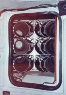
The mass of each battery is 62 kg for the 6STEN-140M model and 72 kg for the 12ST-85R model, and both are 10 kg less if not filled with electrolyte. Due to the enormous mass, it is extremely laborious to replace them through the driver's hatch. It is most convenient to undertake such a task if the turret is lifted from the hull, but otherwise, using the escape hatch is often considered the best option. When using the driver's hatch to replace all four batteries, the process nominally takes 40 minutes.
It is not known how long the tank can fight on battery power alone. For example, the two 12-volt batteries in the Challenger 1 turret have a total charge capacity of 100 Ah and allow the tank to operate in a silent watch mode for a nominal duration of 8 hours. Full discharge of the batteries is not needed to achieve this. The turret of a T-72 requires less power than a Challenger 1 and there is a larger battery charge capacity available. The proportions indicate that a T-72 should be able to carry out a silent watch operation for 24 hours or more without fully discharging the batteries (which would induce premature wear). As it is possible to start the engine pneumatically, the batteries can be discharged to their minimum limit with no real consequences other than the shortening of the battery lifespan. Once the engine is started, the air reserve is replenished by a compressor and the batteries are recharged. It is calculated that the 10 kW generator of a T-72 will take between half an hour to an hour to fully recharge the batteries.
There is a GPK-59 gyroscopic compass for directional navigation located next to the clutch pedal. It is particularly useful when driving underwater as there are no landmarks for the crew to navigate by. The use of gyrocompasses can perhaps be labeled as a rudimentary form of an Inertial Navigation System (INS), advanced versions of which are often present in modern combat vehicles due to their independence from outside input contrary to a GPS-based navigation system.

