Due to the length constraints imposed by Blogger, the original T-72 article was split into two parts. This part covers the second half of the article. You can view the first half here.
TABLE OF CONTENTS, PART 2
- Protection
- Common Characteristics
- Weakened Zones
- Weight Growth
- Protection Criteria
- Object 172 Series (172M, 172M1, 172M-1)
- 80-105-20 Armour
- 60-105-50 Armour
- Appliqué Armour
- Monolithic Steel Turret
- "Kvartz" Turret
- Object 184 Series
- 60-15-15-15-50 Armour
- 60-10-10-20-20-50 Armour
- "Reflecting Plate" Turret
- Background on NERA
- Gill Armour
- Steel-reinforced Rubber Side Skirts
- Kontakt-1
- Kontakt-5
- "Relikt" Side Skirts
- 4S22 Blocks
- Smoke Screen
- NBC Protection
- Firefighting
- Mobility
- Engines
- Cooling System
- Transmission
- Suspension
- Water Obstacles
- Fuel Tanks
PROTECTION
A good indication of a tank's true survivability is its resistance to catastrophic destruction, which can refer to the tendency for a fire to start and the likelihood of that fire spreading and consuming the entire vehicle or the possibility of the ammunition exploding or the death of too many crew members for the tank to continue fighting. The reasoning is that the resistance of a tank to a catastrophic kill (K-kill) is quite distinct from the resistance of a tank to a mobility kill (M-kill) or firepower kill (F-kill). All tracked tanks are equally vulnerable (more or less) to the loss of its tracks from enemy anti-tank fire, and all tanks are generally equally vulnerable (more or less) to the loss of their weapons or their sighting systems from enemy fire. The main difference lies in the ability of a tank to withstand direct hits on its armour and its ability to minimize the damage inflicted on the inhabitants of the tank as well as the internal equipment in case the armour fails. In this sense, the T-72 stands on equal footing with many of its contemporaries and surpasses some of its rivals due to a combination of sturdy armour, a rational internal layout, shock damping mounts for internal equipment and the inclusion of an anti-radiation liner that also behaves as a spall liner. However, many modern tanks now include separated ammunition storage, which is something the T-72 lacks and has proven to be an issue in certain circumstances.
Regardless, the protection level of the T-72 was remarkably high for its time as a result of its combination of thick armour and low silhouette and the low placement of ammunition in the hull reduced the chances of the ammunition suffering a direct hit. The main drawback of the location of the ammunition is that any fuel or hydraulic fluid leakage will inevitably pool on the floor of the hull and if an internal fire is started, it will reach the ammunition eventually. The best practice is for the commander to give the order to bail out and then press the master switch for the fire extinguisher system, thus greatly reducing the chances of an ammunition explosion from occurring before all crew members escape.
The location of the batteries in the front of the tank as opposed to the engine compartment reduces the chances of the tank losing its electrical power if the engine compartment was hit. This gives the T-72 a better chance of surviving an internal fire as the fire extinguishing system will still have electrical power, and the smoke grenade launching system can still be used to obscure the tank from further attack. If the batteries at the front of the tank were hit by a frontal armour perforation, the tank may not necessarily lose electrical power as the generator in the engine compartment is still intact. The only problem is that the engine cannot be started electrically after it is turned off without a battery replacement, but it is still possible to start the engine with compressed air. The compressed air cylinders are refilled by an engine-driven compressor, so the tank can remain fully autonomous indefinitely without batteries if necessary, as long as it has fuel. This high level of redundancy contributes to a high level of survivability as the tank can still continue to fight after sustaining serious damage.
Besides a disinclination to internal fires, the survivability of the tank was enhanced by its low profile. Even though it was certainly not the shortest of all Cold War era main battle tanks, it was still an impressively diminutive target. The original T-72 had a height of 2.19 meters (measured up to the turret roof) and the T-72A was the same. The T-72B had a marginally taller turret along with slightly more ground clearance, combining to slightly increase the height of the tank to 2.23 meters. Overall, the tank is shorter than the T-62 and T-54/55 that preceded it, and compared to tanks like the M60A1, the T-72 can only be described as a dwarf.
Although the tanks produced in the Soviet Union are most famous for emphasizing low size and weight, the reality is that all nations were actively pursuing such reductions and the Leopard 2 and M1 Abrams were examples of West Germany and the U.S making great strides towards this objective. Even so, the T-72 was still slightly shorter than the M1 Abrams and Leopard 2 which had a height of 2.39 meters and 2.48 meters respectively (measured up to the turret roof). In terms of height and overall profile size, it is beaten only by the Strv 103 which also had the upper hand in terms of overall length. By comparison, the Strv 103 had a height of only 1.9 meters when the suspension is in the travelling condition, and having a "bullpup" configuration gave the Strv 103 a uniquely short overall vehicle length without compromising gun barrel length such that its ability to maneuver through dense forests could be better than other tanks. The difference in size can be seen in the drawing below, and the drawing below it comparing the Strv 103 with the M60A1 gives a reference point. Both drawings are taken from "Kampfpanzer: Die Entwicklungen der Nachkriegszeit" by Rolf Hilmes.


The three film stills below show drawings that superimpose the T-72 on comparable NATO tanks to illustrate the difference in the size. The scale appears to be slightly exaggerated in favour of the T-72 in these drawings; the height of the M60A1 seems to be warped as the turret is depicted is too tall and the commander's cupola is too short. Despite this, these drawings are accurate enough to gain a general impression of the difference in size. These film stills were taken from archival footage from a Czechoslovakian Army training film. Original video from the VHU channel.

However, even though the Strv 103 is shorter than the T-72, the casemate hull is still significantly wider, especially at the top part due to the large sponsons over the tracks. Overall, the area of the frontal silhouette of the Strv 103 including the tracks is 4.25 sq.m whereas the area of the frontal silhouette of the T-72 is only 4.0 sq.m, which also happens to be half of the frontal silhouette of the M60A3 (8.0 sq.m). As such, despite being slightly taller than the Strv 103, the T-72 manages to still present a comparatively smaller frontal projection if both tanks are travelling over open ground. Needless to say, this is not a trivial achievement.
In a hull-down position where the height of the turret matters more than the tank's full silhouette, the small turret of the T-72 also has an advantage. With a maximum height of just 750mm when measured from the hull roof to the highest point of the turret roof, the T-72 turret is slightly taller than a T-62 turret (720mm) but shorter than a T-54 turret (810mm). The difference between foreign tank turrets is even more noticeable: the Centurion Mk.10 turret had a height of 956mm, the Chieftain turret had a height of 975mm, and the M60A1 turret had a height of 970mm. A large amount of effort was spent to reduce turret heights in the West, resulting in the turret of the M1 Abrams (and all variants thereof) having a height of 900mm. On page 2409 of the "Department of Defense Authorization for Appropriations for Fiscal Year 1983", it is asserted that the projected area of the M1 Abrams turret is equal to the M60A1, but has a lower profile. From the side, the projected area of the M1 turret is stated to be approximately 6% smaller than the M60A1 turret. The M1 turret could have been shorter, but there was a need to have a sufficiently large internal height to accommodate a human loader and some of this height had already been sacrificed because of the short hull with a reclined driver's seat. Together, the combination of a lower turret and hull gave the M1 a smaller overall projected area compared to the M60A1. The Leopard 2 had a conventional driver's seat and a taller hull, so the turrets of all models of the Leopard 2 (excluding the latest models with additional roof armour) could afford to have a reduced height of 830mm, less than the Abrams. The reduction in turret height was a objective worth achieving even if the projected area is not reduced.
Additionally, the difference in the area of the silhouette of the T-72 does not merely manifest from a frontal view, but also when the turret is turned to one side. When the turret is turned to the side such as shown in the drawing below, the area of the silhouette of the turned turret (dark grey) is the same as the area of the silhouette of the turret when it is facing straight forward (light grey). On the other hand, the area of the silhouette of the turret of an M1 Abrams when it is turned (dark grey) is significantly larger than when the turret is facing straight forward (light grey). The same principle is true for turreted tanks with long bustles like the M60A1 and the Leopard 2. Drawing taken from "Kampfpanzer: Die Entwicklungen der Nachkriegszeit" by Rolf Hilmes.

The increase in the area of the silhouette of the turret has the effect of increasing the chance of receiving a hit on the turret. Additionally, this advantage is non-trivial in a defensive scenario where both tanks are hull-down, dug-in and concealed. The longer turret of an M1 Abrams or Leopard 2 will appear larger to an observer when it is turned away from his direct line of sight, thus making it easier to see. This also has the side effect of causing the movement of the turret to become more obvious, as the change in silhouette size during the rotation of the turret will be more likely to invite the attention of watchful eyes. The lack of any change in the silhouette of a T-72 turret as it rotates renders it harder to notice. Of course, these advantages may be nullified under certain circumstances, such as those facing Iraqi tankers during the first Gulf War. Many T-72M and T-72M1 tanks were dug-in and hull-down, but were easy to see due to the featureless terrain of the desert, especially from the sky. Furthermore, the dug-in tanks baked for hours directly under the hot sun, making them glow brightly in the thermal imaging sights of Coalition tanks and infantry fighting vehicles. These problems are not present in a hypothetical European battlefield due to the abundance of foliage and shade.
The use of a long turret bustle is not inherently bad, of course. Like any other technical solution, it has its own set of merits and demerits. The merits include better turret balance (because the long bustle behaves as a counterweight to the heavy gun and armour at the front of the turret), and quicker loading speed for both manually loaded tanks and tanks with autoloaders if ammunition is stowed in the bustle. This is confirmed by ergonomics studies on manual loading and by autoloader optimization studies done in the USSR. Of course, the downside to having ammunition stowed in the bustle is that the turret is statistically more likely to be hit so that ammunition stowed inside is also more likely to be hit if the turret armour is defeated, and this is quite an important consideration to make. When the turret of a tank with a long bustle is turned to the side, it becomes possible to hit the bustle from the front. For tanks without compartmentalized ammunition and blowout panels like the M60A1, the thin side armour makes it comparatively easy to perforate the bustle armour compared to the frontal armour, thus making it possible for even obsolete anti-tank weapons to defeat the tank from the frontal arc. This is mostly avoided in the M1 Abrams, but not entirely.
Offensively, the smaller overall size of the tank made it more difficult to hit when it was on the move in open terrain. Defensively, the low turret made it hard to detect and even harder to hit, and the armour protection of the turret could also be enhanced if the tank is on a reverse slope. The roof of the turret is angled at around 78-80 degrees, so when the tank is on a gentle reverse slope and the gun is laid at the maximum depression angle of -6 degrees, the angle of the turret roof becomes 84-86 degrees (critical ricochet angle for virtually all long rod APFSDS) and the projected area commander's cupola is partly hidden behind the turret cheek armour, thus minimizing the weakened zones of the turret and making the tough frontal protection of the turret even tougher.

The superior target-finding capabilities of the hypothetical enemy granted by the widespread adoption of thermal imaging technology would also be negated if the tank were hull down, as the hot engine and running gear would be concealed below ground level while the turret may not be hot enough to offer sufficient thermal contrast, especially if it were covered in camouflaging elements like special netting and foliage cloaks or even field expedient solutions like branches. The main factor that gives the surfaces of tank armour a different thermal signature from the surrounding environment is the heating of the steel by solar radiation at a different rate than soil and vegetation, so by covering these surfaces with netting and branches, it is possible to strongly reduce or even eliminate the thermal signature of the tank. On a typical T-72 from the 1980's, a few parts of the tank such as the steel-reinforced rubber side skirts, the plastic gun mask cover, and the anti-radiation cladding on the turret are thermal insulators by design, particularly the anti-radiation cladding as it is designed to resist the heat flash from a nuclear blast. These external components reduce the thermal signature of the tank and may expedite the camouflaging process.

To summarize, the T-72 was not just a capable offensive tool but also quite formidable when used defensively. The only drawback was the slow reverse speed which prevents the tank from quickly withdrawing from a compromised position and performing an effective tactical retreat. However, the slow reverse speed would not have been an issue when firing from a hull defilade behind a reverse slope or a berm as it is quick enough for the tank to rapidly return to a turret defilade. This is mainly due to the low height of the turret, which means that a lower reverse speed is sufficient to completely hide the turret within the same time period as a tank with a taller turret and a quicker reverse speed.
Of course, it is not possible to remain completely unseen indefinitely. The formidable armour of the tank is the most obvious major factor in reducing the casualty rate of its crew and ensuring the success of a combat mission, but the criteria for knocking out a tank does not only depend on defeating its armour. In fact, it is not only possible to disable a tank without perforating its armour plating, but also quite common. One of the easiest ways to do so would be to simply de-track the tank, but the tank can still fight albeit from a compromised position. Another effective method of eliminating the combat capability of a tank would be to destroy its observation devices. In that case, the most important objective would be the destruction of the gunner's sights which would prevent the tank from using its weapons.
The location of the gunner's sight aperture depends on the individual tank, but generally speaking, tanks with a telescopic gun sight have the sight aperture in the gun mantlet or near it, making them vulnerable to damage. For a tank like the T-54, the sight aperture is located in a slit cut into the turret armour next to the gun barrel, directly at the center of mass of the tank where most shots are expected to land. Furthermore, a hit from a solid armour-piercing shot on the well-sloped upper glacis may produce enough secondary fragmentation to damage the sights indirectly, and the detonation of an explosive shell on the upper glacis is quite likely to do so owing to the large amount of fragmentation expected. Tanks with a periscopic gun sight usually have the gun sight aperture located on the turret roof or some other part of the turret above the frontal armour facings. The T-72 belongs in this category as the aperture of its primary sight and night vision sight are both located on the turret roof, making it less likely to be damaged by explosive shells impacting the front of the turret or the upper glacis.
The T-72 has proven its worth in various conflicts when placed under competent command, but the lack of media coverage on the successes does not help its case. Even though many tanks have been destroyed, often irrecoverably, many more have survived such that the tank's ability to endure severe punishment simply cannot be considered low. To list one incident in Grozny, in the year 2000, a T-72B with the tail number 611 took 3 hits from Fagot anti-tank missiles and 6 hits from RPGs during 3 days of intense fighting and remained in battle with only minor damage. Most of the hits landed on the sides of the tank, with one rocket impacting the lower rear of the hull. Other cases involving older models such as the T-72A more often ended on a sadder note, but in general, it took several hits from anti-tank grenades and missiles to reduce the combat capacity of a T-72 and at least half a dozen hits on the weakened zones (sides, rear) are usually required for the ammunition to detonate or a fire to start in the tank.
More examples come from a World of Weapons magazine article (March 2005 issue) on tank action in Grozny containing details on multiple T-72As lost in combat. The 131 Separate Motor Rifle Brigade (OMSBR) tasked with capturing the Grozny rail station sustained many casualties during combat, losing a total of 157 men, 22 tanks, 45 infantry fighting vehicles, 37 cars and all 6 of the Tunguska anti-aircraft systems operated by the air defence division attached to the brigade. While providing supporting fire, the tanks belonging to the brigade received multiple anti-tank grenades from every direction in return for each shot fired. One T-72A with the tail number 533 sustained four or five RPG grenade impacts on the engine compartment, and the tank caught fire. It eventually exploded, long after the crew escaped. Another T-72A, with the tail number 537, withstood six or seven hits from RPG grenades before suffering an ammunition explosion, killing its entire crew instantly. A third T-72A, with the tail number 531, sustained four hits from RPGs before its turret drive failed, and the tank was finally knocked out of action after an APFSDS round fired from 100 meters impacted the turret on the commander's side. A fire was started, but fortunately, the gunner (left hand side of the turret) was only heavily concussed because the bulky breech assembly of the cannon saved him from the spall and fragments entering the turret on the commander's side (right hand side of the turret). Both the gunner and driver were able to escape the tank before it eventually succumbed to the fire and exploded 20 minutes later. None of these tanks had reactive armour installed.
In another example, a T-72B1 from the 276 Motor Rifle Brigade with the tail number 221 was penetrated twice in combat during the battle for the Grozny hospital in January 16, 1995. After repairs, it was damaged again on January 21, 1995 during combat near the building of the Council of Ministers where it was hit with five RPG grenades. Four of the hits were located on the sides of the hull, one of them on right side, on the fourth roadwheel, and the other three on the left side. The fifth hit was located on the turret, above the gun barrel. The autoloader was damaged by the turret strike, but the tank survived and was sent for an overhaul.
More interesting examples can be found in the article "Танки Т-72 В Войнах И Локальных Конфликта" (T-72 Tank in Wars and Local Conflicts) by V. Moiseev and V. Murakhovsky and published in the "Arsenal of the Fatherland" magazine, issue 4, 2013. One of them is taken from an after-action report on the death of a tank commander in a T-72 after an attack by RPG-type weapons. The tank was a T-72B1 built in December 1985 in Uralvagonzavod. After being pulled into a repair facility, the tank was inspected and eight damage points were observed. Five of the hits were recorded on the hull, and of these, three were from RPG grenades impacting the sides of the tank in the areas protected by reactive armour, one was from an RPG grenade impacting the rubber side skirt of the tank in an area unprotected by reactive armour, and one was from a fragmentation grenade (possibly a VOG-17M) impacting the rear of the engine compartment. The remaining three hits were recorded on the turret, one on the front, one on the side, and one on the rear.
It was noted that the tank was in a marching status prior to the attack, having the cannon locked in the travel position and the 12.7mm machine gun locked facing backwards. Also, the commander's hatch was ajar or opened completely, so that the death of the commander was most likely caused by the combined explosion of an anti-tank grenade and the reactive armour occurring outside the tank, given that the armour was not perforated. Overall, the tank remained combat capable despite receiving damage in the autoloader and in the stabilizer system, as the driver and the gunner were still alive at the end of the ordeal and the gun could still be fired using the manual controls.
In general, photos of destroyed T-72 tanks cannot be said to be proof of the low survivability of the tank, but are instead often indicators of the sheer ferocity of the fight that led to its destruction.
COMMON CHARACTERISTICS: HULL
The protection qualities of the frontal armour depend greatly on the specific model, but there are many characteristics that were shared across all models. This includes the side armour, hull belly armour, hull roof armour, and others. Protection was focused on the frontal arc of the hull.
The frontal arc of the tank is not the same for the hull and the turret. Various definitions of a tank frontal arc are handily compiled in the drawing below, taken from the article "Elements of Tank Design" by Gerald A. Halbert published in the November-December 1983 issue of the ARMOR magazine. For the hull, the Soviet definition of the frontal arc places the center point of the arc at the centerline off the hull (first from left). For the turret, the center point of the frontal arc is placed at the center of the turret (first from right). When the effective armour protection is given for the turret, it is almost always referring to the frontal arc protection using a reference side angle of 30 degrees under this frontal arc definition.

The Soviet definitions are used throughout this article and other Tankograd articles.
Generally speaking, the level of protection was quite formidable although some concessions were made during its development which put it slightly below the level of the T-64A. It is widely known that increasing the volume of a tank leads to an increase in armour mass without an increase in armour thickness because of the need to add armour to protect a larger surface area. This was a source of inefficiencies in the design of the T-72. When the UKBTM design bureau of the Uralvagonzavod factory designed the Object 172 prototype using the T-64A as the foundation of their new tank, one of the modifications made was to replace the compact 5TDF opposed piston engine with the V-46 V-shaped 12-cylinder engine developed by the Chelyabinsk tractor plant (ChTZ). The V-46 engine itself was larger than the 5TDF, but the difference in dimensions was not as significant as the decision to use the conventional centrifugal fan-driven cooling system from the T-54 instead of the ejection-type cooling system of the T-64. The volume of the engine compartment had to be increased by 0.5 cubic meters to accommodate this new equipment, and in turn, the increased volume generated a larger surface area. Added together with the increased mass of the running gear, the weight of the T-72 increased considerably and none of the extra mass went towards thickening the armour. To the contrary, the side hull plating had to be thinned down to 80mm from 85mm in order to put the weight gain in check. This was partly nullified by the larger diameter roadwheels of the T-72 which could cover parts of the hull, but the wheels are made of aluminium and not particularly thick, so this was not a true remedy but merely an unintended bonus.
The hull side, hull roof, hull belly and rear armour of all T-72 models are identical, regardless of the variant. As stated earlier, the armour of the side of the hull is 80mm thick. Tthe armour on the sides of the engine compartment is 70mm thick. The side armour of the hull is more than enough to withstand 20mm armour-piercing ammunition fired from various aircraft as well as 20mm and 25mm APDS rounds from autocannons.
There are several zones in the side of the hull that may not be entirely on the same level as the rest of the armour such as the one shown in the photo below. As you can see, the thickness of the steel armour at the drive sprocket and the rear shock absorber is reduced. It is thinner than the side armour of the engine compartment, and even though the shock absorber unit and the drive sprocket are backed by some amount of armour, the level of protection at these zones is not equal to the side of the engine compartment.


Note that in the first photo, the cut in the armour plate above the shock absorber is angled whereas the same cut is perfectly horizontal in the second photo. This is because of the slight offset of the roadwheels caused by the use of a torsion bar suspension. On the T-72, the roadwheels on the left side of the hull (port) are displaced slightly forward from the roadwheels on the right side (starboard). As such, the roadwheels on the right side of the hull (starboard) are slightly closer to the drive sprocket, so the shock absorber for the sixth roadwheel had to be moved closer to the drive sprocket and angled slightly to facilitate the same range of vertical travel.
The thickness of the armour at the holes for the installation points for the shock absorbers and the final drives is 40mm. The shock absorber itself has a casing made from armour-grade cast steel and has a considerable bulk which adds some protection on its own, and the final drive is protected by the drive sprocket and the drive sprocket hub.

Besides these weakened zones, the mounting points for the roadwheels and track support rollers can be considered reinforced zones. The armour thickness at these zones is much greater than the parts of the hull where they are located. The mounting points for the roadwheels are especially thick as they are separate milled blocks of steel welded onto the belly plate. The thickness of steel at the mounting points for the roadwheels probably exceeds 100mm and the thickness of the steel at the mounting points (also thick blocks of milled steel welded) for the track support rollers easily exceeds 100mm.
The side armour is thickest at the top half and thins down to just 20mm at the lower quarter of the side hull profile. The upper and lower sides are not the same plate. The upper side armour is a single rolled steel plate whereas the lower side armour is actually a part of the belly armour plate. The belly plate is a large stamped piece of steel, bent into a tub shape and welded to the upper side armour. It joins with the upper side plate at an angle of 32 degrees from the vertical axis. The lower side hull armour has a height of 250mm or 270mm if the thickness of the plate itself is included. The upper side hull occupies around three quarters of the area of the side hull profile and the weaker lower side hull occupies one quarter. This thin strip of the side armour is usually not visible as it is completely concealed behind the roadwheels which add a modicum of spaced armour. The roadwheels cover a height of around 350mm of the lower part of the hull, and thus cover the entirety of the lower hull sides and also cover a part of the upper hull sides as well. The short height of the lower side hull armour makes it statistically unlikely to be hit and the additional protection provided by the roadwheels offsets the reduced thickness of the armour, so overall, it is not a flaw in the protection scheme of the tank. It is worth noting that the side armour of many other tanks are configured in a similar way, including the Leopard 2 as shown on the right next to the T-72 on the left.


The interior surface of the upper side hull armour is coated in a 45-50mm layer of "Podboi" anti-radiation lining, which can help absorb spall and other secondary penetrator fragments or even stop residual penetration from less energetic projectiles. This is discussed later in the "NBC Protection" section of this article.
It is without a doubt that the sides of the tank were only sufficient for a very limited period of the service life of the T-72. Being only 80mm thick, the side armour plate could offer only a fraction of the protective value of the front armour, and this was not a trifling issue. The number of hits sustained by a tank's sides were statistically significant, as shown by the analyses conducted by Dr. Manfred Held in "Warhead Hit Distribution on Main Battle Tanks in The Gulf". The charts below are from the study.

The sides would have been mostly resistant against 105mm APDS like the L28 round (M392 in the U.S and DM13 in West Germany) at a range of 2,000 meters within a somewhat reasonable 40-degree arc, but this arc is still relatively narrow and it limits the tank's freedom to maneuver in open spaces. At a range of 200 meters, the side armour is only capable of resisting DM13 at a side angle of 17.5 degrees, so the protected frontal arc would only be 35 degrees. The appearance of 105mm APFSDS rendered the side armour completely inadequate as protection against contemporary anti-tank firepower.
The hull roof is 30mm thick, while the thickness of the hull roof around the turret ring is 20mm. It can be seen in the photo below. The rear armour plate over the engine compartment is 40mm thick, sloped at 30 degrees, and the hull belly is 20mm thick. The thickness of the "Podboi" anti-radiation lining on the hull roof is 50mm. As it is not inhabited by the crew, the engine compartment lacks an anti-radiation lining.

The engine access panel is 20mm thick and is supplemented by a stamped steel radiator cover. The cover is used to seal the radiator during snorkelling operations and it is stowed on top of the engine access panel when not in use. Its contribution to the overhead protection of the engine is limited, but it may prove beneficial against certain threats. For example, the damage from grenades, shells, bombs and other high-explosive ordnance may be reduced by the standoff distance created by the cover. Fragments from airbursting artillery shells may also be negatively affected by the spaced armour effect created by the cover.
The thickness of the hull belly plate is comparable to tanks like the M60 series and is slightly thicker than the 16mm belly plate of the Centurion and Chieftain, but is soundly beaten by the arched 36mm-thick belly of the M48 which was known to have excellent mine protection. The hull belly of the T-72 is only sufficient against explosive charges with a mass of less than 10 kg detonated over the tracks and not directly under the hull. These parts of the hull are most likely constructed from the same steels used in the same locations in the T-54 and T-62: 49 S grade steel for rear armour plate and the hull roof, 43 PSM grade steel for the floor. These grades of steel were first used in the T-54 obr. 1953.
The hull bottom is constructed from a single plate of rolled steel, which is then stamped into a complex shape with protruding ribs for the installation of torsion bars and a depressed section in the floor to accommodate the driver. Reinforcing nubs were pressed into the plate between every torsion bar rib to improve the stiffness of the floor. The side edges of the plate were bent upward at a 30 degree angle to join with the side hull plate, thus forming a tub shape. This was possible due to the ductility of 43 PSM steel, which is a soft annealed steel and cannot be considered equivalent to RHA. 43 PSM has a yield strength of 400 MPa, a tensile strength of 600 MPa, and a hardness of 180-250 BHN. The elongation limit of 25% for 43 PSM is very high compared to RHA. These qualities make the steel plate easy to process by stamping and potentially more useful for mine protection because softer steels like 43 PSM have a reduced resistance to deformation but higher resistance to rupturing compared to high strength and high hardness steels. The rigidity of the belly plate is augmented by the lateral ribs for the torsion bars and the longitudinal embossed nubs on the belly plate.

Initially, cast turrets for the T-72 were made from MBL-1 cast armour steel with a hardness of 270-290 BHN. This grade of steel was first used in the turret of the T-62. The high hardness armour used in the turret of the T-72B is BTK-1Sh, a high hardness, high strength electroslag remelted (ESR) steel with a hardness of around 450 BHN. The appliqué armour plate installed on the 1983 modification of the T-72A and earlier T-72 variants is not known but it has been credited with a hardness of more than 500 BHN by credible sources. In Poland, an armour grade equivalent to MARS 500 was used. In the USSR, BT-70Sh steel may have been used.
The upper glacis is a multi-layered armour array angled at 68 degrees. Although the composition of the composite armour was changed many times over the course of the long career of the T-72, the angle of the upper glacis always remained the same. The high obliquity was an advantage against APDS ammunition, HEAT ammunition (due to fuzing issues) and early composite APFSDS rounds including Soviet models, but additional challenges arose when long rod APFSDS ammunition became commonplace in the 1980's due to the increased performance of long rod penetrators on highly oblique armour. But even so, this did not necessarily mean that the high slope of the upper glacis became a detriment - these matters are not so simple when composite armour is involved. The nuances of this design decision are discussed further later on in this article.
LOWER GLACIS
The armour protection of the lower glacis changed very little during the service life of the T-72. The properties of the plate are identical to the other welded plates used for the hull, like the side armour plate and the front plate of the upper glacis. The lower glacis is reported by some sources to be 80mm plate sloped at 61.5 degrees, identical to the T-64A, but it is stated to be 85mm sloped at 60 degrees according to "Kampfpanzer: Technologie Heute und Morgen" by noted German armour expert Rolf Hilmes. The difference in effective thickness between these two figures is minimal and may be explained by possible variations in discrete T-72 models, but the angle of the lower glacis is marked as 61.5 degrees in the Object 172M factory drawings, lending much more credence to the notion that it is also 80mm in thickness (identical in thickness to the T-64A).
Being a traditionally weak area on most tanks, the relatively poor armour of the lower glacis is largely counteracted by its small size and low exposure to enemy fire. It occupies less than 20% of the total area of the front hull. The low number of hits recorded on the lower parts of tank hulls have been independently verified by multiple sources, as discussed previously in this article in the section on the autoloader of the T-72. Again, it should be noted that statistics on the hit distribution on combat-damaged tanks during WWII showed that 90% of hits were recorded one meter above the ground, as reported by Sergey Gryankin on pages 12-13 in his article "T-54", published in the "Техника-молодёжи" magazine (Technology of the Youth). Moreover, Richard Ogorkiewicz writes on page 394 in "Technology of Tanks" that on average, the first 0.7 meters of a tank's height is covered by the terrain irregularities. If grass or other forms of vegetation are also present, this would mean that the lower glacis of a T-72 would almost always be obscured from direct vision and would usually be physically protected by the terrain due to its low height. Such statistics directly influenced Soviet tank designers in determining the optimal height of the lower glacis.
The vulnerability of the lower glacis can be reduced even further if the tank is in a hull defilade position behind a natural obstacle. Even if the obstacle does not provide enough resistance to stop an incoming projectile, the fact that it hides the lower part of the tank will shift the point of aim upwards, away from the lower glacis.


LOWER GLACIS WITH DOZER BLADE

If natural cover is not available and a static defensive position must be created, it is possible to for any T-72 model to self-entrench using the integral dozer blade installed on the lower glacis. Only the Object 172 prototype tanks created from 1968-1970 lacked a dozer blade. 17 tanks of this type were produced, and they were not delivered to the troops. A dozer blade was present on the Object 172M prototypes created during the summer of 1972 for performance trials (shown in the two photos below), and the final Object 172M model that was accepted into service in the Soviet Army as the T-72 Ural on the 7th of August 1973 had a dozer blade.


The dozer blade can be used for self-entrenchment or to augment existing cover with additional concealment. It also allows the tank to be used as a tractor and a digger for general construction work when specialized vehicles are not available. The blade secured by two rotating latches which are turned with a wrench to release the dozer blade. The dozer blade has a width of 2.14 meters.


The dozer blade is suspended from the belly of the tank by four structural support rods which can be seen in the two photos above. Two of these can be seen in the photo below. When the dozer blade is unlocked and released, these support rods retract backwards into special troughs to orient the dozer blade at the proper angle for digging.

With the dozer blade, the T-72 can be used to build a tank trench for itself in 15-20 minutes on soil. On snow, it can take as little as 5 minutes, but conversely, it takes much longer to self-entrench on frozen dirt. Due to the limited width and capacity of the dozer blade, the tank must make a few passes when digging out a suitably sized hole for itself. The tank commander and gunner exit the tank and continuously guide the driver during this process. Further improvements to the tank's firing position can be done by hand with the pioneering tools carried on the tank (spades, picks).
If necessary, the dozer blade can also be used to overcome anti-tank trenches by filling them in or creating a ramp. This may be the only option for regular tank units if the engineering company of a tank regiment is not available to support them for whatever reason, or if too much time would be wasted in waiting for support. This greatly reduces the effectiveness of such trenches in delaying an attacking force composed of T-72 tanks as compared to any other tank, excluding the T-80 series and later models of the T-64 series.
In the total absence of natural cover, the presence of the upper glacis armour array will partly reduce the height of the lower glacis weakened zone. The photos below (left photo courtesy of Stephen Sutton) shows the thickness of the front plate of the upper glacis array by the seam joining it to the lower glacis plate so that you can visualize the approximate reduction in the size of the weakened zone. The tank on the left is a T-72M1 (formerly Iraqi) and the tank on the right is a T-72M, so both have an improved hull armour array with a 60mm front plate. The dozer blade has some overlap with the array which further minimizes gaps in the armour.


Actual measurements done on a T-72M shows that the distance between the surface of the upper glacis and the edge of the dozer blade is 290mm. Knowing that the upper glacis has a thickness of 215mm on the T-72M, the gap between the area of the lower glacis protected by the dozer blade and the area overlapping with the upper glacis is only 75mm. When viewed from the front, the height of this gap is around 37.5mm, or just one and a half inches. Needless to say, hitting this part of the lower glacis is extremely challenging. On its own, the lower glacis plate is highly vulnerable to 105mm APDS, but this vulnerability is greatly reduced by the aforementioned factors.
The dozer blade is a very thick and heavy steel plate. According to T-72 manuals, it weighs 200 kg. It is probably made from a high hardness abrasion-resistant or armour grade steel. It is very likely that high hardness armour steel grade is used for the dozer blade of a military vehicle like the T-72 because a high hardness blade can be used to shift abrasive rock and frozen soil as well as provide additional ballistic protection. Case in point - high hardness impact resistant steels like Hardox 500 are standard for bulldozer blades and loader buckets used in mines and construction sites where large quantities of rock must be shifted, and high hardness steel dozer blades are also standard for military combat engineering vehicles. The measurement on the left below (done by Jarosław Wolski) shows that the thickness of the dozer blade on an old Polish T-72M1 is 20mm. The measurement on the right, taken from the T-72.org Facebook group, shows that the dozer blade of a T-72M is also around 15-20mm thick, although it is not possible to be sure. The measured dimensions are congruent with the given weight of 200 kg. At an unknown point in the production of the T-72, possibly beginning with the T-72B, the thickness of the dozer blade was increased to 25mm. This increased its weight to 250 kg. The T-90 and T-90A are verified to feature this thickened dozer blade.


Due to the obscurity of this topic, it is rather difficult to ascertain if the T-72M and T-72M1 differed from their domestic counterparts in the thickness of the dozer blade. However, it seems safe to assume that if the T-72M1 had a dozer blade with a thickness of 20mm, then the T-72A would also have one of the same thickness. It is worth noting that the dozer blade is not simply laid on top of the lower glacis plate, but it is actually slightly spaced. This is shown in the drawing below, taken from a T-80B manual. The T-80B has the same dozer blade installed.

This is beneficial against AP and APDS ammunition. An armour configuration consisting of a high hardness steel plate on top of an RHA plate at high obliquity is more effective than a solid RHA plate of the same weight, which is not only demonstrable with test firings against laboratory model targets but also in live fire tests. E.g. the solid 118mm RHA upper glacis of the Centurion Mk. 7 and Mk. 8 was found to be noticeably less effective on a thickness basis compared to the uparmoured upper glacis of Centurion Mk. 3 and Mk. 5 tanks, consisting of a 44mm RHA plate welded on top of the 76mm base RHA plate. The presence of an air gap between the two layers can provide an additional benefit against AP and APDS, supplementing the positive effect of layered armour.
The overlapping section between the upper and lower glacis plates combines with the dozer blade to make the lower glacis a problematic target to defeat. To put the level of protection into perspective, Rolf Hilmes credits the lower glacis of an ex-East German T-72M with 250mm RHA of protection against KE attack, which is incongruous with the combined LOS thickness of the lower glacis and dozer blade on their own (only around 208mm). This appears to be the only published figure on the armour value of the lower glacis. It is worth noting that if Hilmes' figure is correct, then the weakest part of the T-72 hull is nominally more resilient than the frontal armour of a T-54 and is on the same level as the turret armour of the Chieftain tank, especially after the slope of the armour is considered. The additional 5mm of thickness for late T-72 models increased the effective thickness slightly, but did not change the fundamental level of protection.
In all likelihood, L52A1 or M728 APDS with a penetration of 130mm at 60 degrees at 1 km and 120mm at 60 degrees at 2 km may fail to defeat the lower glacis from a range of approximately 1.5 km and more. The older L28A1 or M392A2 rounds had significantly worse performance on oblique armour and would certainly fail to defeat the lower glacis from 1 km or less. Of course, the L15A4 APDS round fired from the 120mm L11 with a penetration of 130mm RHA at 2 km should succeed against the lower glacis of the T-72 quite easily from any distance. Needless to say, these ranges would be unacceptable for the main armoured surfaces of the tank, but for a minimally exposed target such as the lower glacis, it is a very respectable level of protection, especially when compared to tanks like the Chieftain or M60A1.
It is worth noting that according to Russian historian Mikhail Pavlov mentions that the lower glacis plate of an Object 432 (T-64) can be nominally defeated by 105mm "subcaliber shells with a muzzle velocity of 1,475 m/s" at a distance of 2,500 meters, which is the same distance limit given for the lower glacis of the T-55 and T-62 (100mm RHA at 55 degrees). The lower glacis of the T-64 is the same as the T-72, but the tank lacks a dozer blade. HEAT rounds of a modest caliber would not face any difficulties in defeating the lower glacis armour, but against HESH, the physical separation of the dozer blade from the lower glacis fulfills the essential role of preventing the transmission of stress waves to the lower glacis plate from the blast, which prevents spalling. The considerable thickness of the blade itself allows it to resist deformation and thus fulfill its function even when impacted by HESH shells of a large caliber, as tests on Conqueror tanks have shown that thinner 14mm spaced plates ("burster plates") were effective at defeating 183mm HESH shells and Malkara missiles (HESH warhead).
However, all of this is only true if the incoming projectile impacts the middle section of the lower glacis, as the lower part of the lower glacis has a reduced thickness. For the original T-72 Ural model, the reduction in thickness was a necessity because the torsion bars for the first pair of roadwheels are in the way, as you can see in the drawing on the left below (T-72 Ural). However, the geometry of the lower glacis was changed at an unknown time and became even thinner at the area in front of the torsion bars, as shown in the drawing on the right (T-90). Also note that the dozer blade on the T-90 is not spaced from the lower glacis plate, or has so little spacing that it is practically irrelevant.


COMMON CHARACTERISTICS: TURRET
The turret is a two-piece casting. The walls, base, the bulge for the commander's cupola and some parts of the turret roof are formed from a single casting, onto which the cast roof is welded. The side armour is curved at a considerable rearward angle to form a point at the very back of the turret, forming a teardrop shape. This was especially exaggerated in the T-72B variant due to the larger and thicker turret cheeks, which earned it the humorous "Super Dolly Parton" moniker. The rear of the turret of all T-72 variants have a distinct step joining the turret roof to the bulge at the rear of the turret. This was inherited from the turret design of the T-64A, like so many other details of the T-72 series.

As there is no discrete transition from the frontal cheek armour to the side armour owing to the complex shape of the cast turret, the turret sides are simply defined as the region of the turret directly next to the crew seats, labelled 'Д' in this drawing of a T-64B turret. As mentioned before, the side of the turret has a physical thickness of around 80mm near the base and the curvature of the turret sides provide a minor increase in line-of-sight thickness to around 88mm when viewed perpendicularly. The turret sides becomes negligibly thinner towards the roof, but the curvature of the turret enables the same line-of-sight thickness to be maintained along the entire height of the sides. The amount of vertical sloping is relatively minor as the turret is built with a heavy emphasis on horizontal shaping; the side of the turret is horizontally sloped rearward at an angle of 42 degrees, as measured tangentially to the side of the turret. The LOS thickness of the side armour is therefore 118mm when viewed perpendicularly. The rear of the turret is around 65mm thick, but varies considerably in actual protective value due to the complex shape of the casting. This part of the turret is notably tougher than the T-64 and T-80 pattern of turrets as they are completely flat and therefore have a lower effective thickness.

With a thick layer of anti-radiation lining backing it and with the storage bins (plus cargo) adding a modicum of resistance, the sides are more than enough to withstand any 20mm and 23mm shell at point-blank and any 25mm autocannon shell at the higher end of typical combat ranges (in the vicinity of 1,500 m) when hit at a perpendicular angle. This is including the 25mm M919 APFSDS shell. However, the armour is not thick enough to reliably resist 30mm, 35mm and 40mm shells. In order to do so, the shot must impact the side armour from the frontal arc of the turret and not perpendicularly to the side. The rear of the turret, however, is only sufficient against 20mm autocannons unless it is attacked at a considerable angle of incidence, although the rear armour is actually somewhat pointed due to the teardrop shape of the turret. This would certainly improve the level of protection. From a perpendicular angle of attack, the turret cheeks can still offer a respectable defence due to the large thicknesses of steel, but the sides of the turret over the crew stations provide only a modicum of protection from light shoulder-fired HEAT grenades weapons like the M72 LAW. The presence of stowage bins made it difficult to achieve reliable penetration with such small caliber grenades, particularly when they were fully packed with spare parts and equipment, but it was not a comprehensive remedy.

On the T-72B3 UBKh, the sides of the turret have been completely covered with an advanced ERA kit capable of defeating tandem warheads at the expense of valuable stowage space and the rear has been reinforced with slat armour.
The shape of the turret of the T-72A and T-72B is such that the sides will be completely unreachable by enemy fire from within the frontal 70-degree arc. This means that if the side of the turret was shot at an angle of attack of 35 degrees, the thin sides of the turret will be hidden behind the turret cheeks. If the angle of attack is increased to 45 degrees, the sides will be visible, but the angle of incidence will increase to 87 degrees - steep enough to guarantee a ricochet. When the angle of attack is increased to 55 degrees, the angle of incidence is still 77 degrees. This is steep enough that many shaped charge warheads will fail to fuse and APDS projectiles are very likely to ricochet. Even if an attacking projectile manages to dig into the armour, the LOS thickness of the thin side armour from the horizontal angle of the turret alone at such a steep angle of incidence is very formidable at 391mm. This is already enough to resist the majority of shoulder-fired HEAT weapons used by opposing armies. This is also a noticeably higher level of protection than the side turret armour of the Abrams series from the M1 to the M1A2, as that only offers an effective thickness of 380mm RHA against an 81mm shaped charge warhead from a 45-degree side angle. The difference in the level of KE protection is even greater - the homogeneous cast armour at this zone of the T-72 turret would offer between half as much to twice as much protection at 55 degrees based on the calculated thickness efficiency coefficients of the Abrams turret side armour, and the protection provided at 45 degrees is infinitely higher because the angle of incidence is simply too high (87 degrees) whereas the side of the Abrams turret would offer only around 200mm RHA in effective thickness.
In other words, the turret of the T-72 is a very, very tough nut to crack from a wide range of angles. The unique teardrop shape of the turret makes it possible to present a high thickness of armour across the frontal arc and, more importantly, accomplish this without adding excessive weight to the tank. Indeed, based on the hit distribution data from multiple conflicts during the 20th Century, the teardrop shape is mathematically ideal for conventional large scale mechanized warfare on a fundamental level. This shape could not have been implemented effectively without restricting the turret crew to two men, and in turn, a combat-effective two-man turret design could not have been implemented without an autoloader.
However, this shape does not come without drawbacks. It is extremely efficient in the distribution of armour mass because it can provide a very high level of protection in its frontal arc with comparatively little armour compared to heavier turrets, but because the vast majority of the mass is disproportionately allocated to the front, the turret also became unbalanced. It is quite the opposite for NATO tanks like the M60A1, Chieftain, Leopard 2, M1 Abrams, AMX-30, and even the Leopard 1 to some extent. For these tanks, the inclusion of a large bustle containing ammunition or other equipment was a convenient counterweight to the frontal armour, thus shifting the center of gravity closer to the geometric center of the turret ring. This not only reduces the load on the horizontal turret stabilization system when the tank is situated on non-level ground and especially so when the tank is in motion over rough terrain, but a balanced turret also generates a more stable load on the stabilizer, making it easier to implement faster and more precise turret rotation drives, and it also reduces the stress on the turret ring from firing the main gun at various gun elevation angles and at various tank orientation angles. For instance, the turret of a basic T-72A weighs 12 tons (including the weapons and a full set of standard equipment) and its center of gravity is 500mm above the level of the turret ring race ring and horizontally offset 430mm from the geometric center of the turret ring. The turret of the T-72B has even heavier frontal armour and is even more unbalanced, and the addition of explosive reactive armour on the frontal arc further exacerbates the issue.
Tanks like the T-64B and T-80B used externally-stowed auxiliary equipment as counterweights with limited success. Presently, the relatively new T-72B3 UBKh modernization shifted more weight to the rear of the turret when reactive armour blocks were added to the sides of the turret over the inhabited zones and a slat armour screen was installed over the rear of the turret, but again, the effect is still limited simply due to the massive allocation of armour mass to the turret cheeks. More recently, the approach taken by Uralvagonzavod engineers with the new Proryv-3 turret of the T-90M can be seen in the retention of the teardrop shape and the addition of a segregated ammunition compartment to the bustle to act as a counterweight and to reduce the quantity of ammunition stowed openly in the fighting compartment. This solution is not perfect, but it is a suitable adaptation of the basic teardrop geometry for modern needs.
Nevertheless, the unbalanced turret of the T-72 is still lighter than the turret of tanks like the M1 Abrams or Leopard 2. The turret of a Leopard 2A4 reportedly weighs 16 tons (fully equipped), and would weigh even more if the designers had decided to provide any serious amount of protection for the sides of the turret bustle. As it stands, that is the weight of a Leopard 2A4 turret with only 80mm of flat RHA steel protecting the sides of the turret bustle (4 times less protection than the sides of the T-72 turret). In this respect, the T-72 turret design certainly has a major advantage and the decision to use a teardrop shape for the turret could be considered eminently justifiable.
The turret ring of the T-72 is a simplified form of the T-64 turret ring design with the MZ autoloader carousel mounting ring removed. The design was created based on the T-54 and T-62 turret designs which placed the ball bearing race ring of the turret ring above the level of the hull roof in a cutout in the turret armour. This made the structure vulnerable to jamming from direct hits to the lower edge of the turret where the turret ring was located as the thickness of the armour is lower. For the T-72, the hull roof around the turret ring is thinner (20mm) than the hull roof above the driver's station (30mm) to accommodate the turret ring, but even so, the ball bearing race ring is still located in a cutout in the turret armour, above the level of the hull roof. As such, only a limited thickness of turret armour is present in front of the race ring, which poses a problem if an armour piercing round impacts the joint between the turret and the hull as it is much more likely to defeat the armour and jam the turret ring or enter the tank and cause internal damage. The turret ring design is shown in the two drawings below. The drawing on the left shows the rear of the T-72 turret and the drawing on the right shows the front.


The difference between the T-64 and the T-72 turret ring designs is apparent when they are compared. The T-72 turret ring is shown on the left with the interior of turret ring facing to the right of the drawing, and the T-64 turret ring is shown on the right with the interior of the turret ring facing to the left of the drawing.


Two rubber gaskets below the ball bearing race ring seal the turret ring from water ingress. A raised collar prevents artillery splinters and bullets from slipping into the gap between the turret and the hull roof. The depression of the hull roof around the turret ring can be seen in the photo below along with the protective collar.

The merits of various turret ring protection methods are examined in the study "Некоторые Вопросы Проектирования Защиты Стыка Корпуса И Башни" by O.I Alekseev et al. It was noted that turret ring designs that required a cutout in the lower part of the turret like the T-54 turret was a liability. Conversely, the solution implemented in the M48 Patton, M60 and M103 where the turret ring was installed in a raised flange cast together with the hull was also assessed to be a non-ideal solution as it still fails to prevent the turret from being jammed by a hit to the joint between the turret and the hull. The low thickness of the flange also results in a low level of armour protection. The best solution was found on the IS-3, T-10, Chieftain, Leopard 1 and M46 Patton. These tanks had the ball bearing race ring recessed below the hull roof, and in the case of the T-10, M46 and Chieftain, the gap between the turret and the hull roof was covered by raised parts of the hull. For example, the Leopard 1 shown below clearly has the turret ring race ring placed below the hull roof (photo taken by T. Larkum). The T-72 turret ring design belongs somewhere in between the first and third categories as the ball bearing race ring is still installed in a cutout in the lower part of the turret, but the height of the race ring is reduced compared to the T-54 and T-62.

At the front of the turret, the cast steel gun mask can be considered a common feature of all T-72 variants, although this is not true in the strictest sense as the gun mask is different depending on the model of cannon mounted in the tank. The gun mask is a single solid steel casting that is bolted on the gun mounting cradle. The gun mask has a width of 390mm. It does not contact the gun barrel and does not interfere with the harmonics of the barrel, nor does it have any effect on the dynamics of the recoil stroke of the cannon. The gun mask is connected to the co-axial infrared spotlight on the right of the gun by a set of pushrods that allows the spotlight to be aimed vertically in sync with the tank's night vision sight albeit with a great deal of horizontal parallax if the spotlight is used at a different distance than the distance that it was previously calibrated for.
The gun mask has a ring of screws around the base of the barrel which are designed for securing a plastic gun mask cover. The cover is meant to prevent rain from ingressing the tank through the gap between the gun mounting cradle and the turret, but it also functions as a seal to prevent the ingress of NBC contaminants. The photo below by Thomas Voigt shows the gun mask of a T-72M with a plastic cover.

The ring of screws is also used in tank models with Kontakt-1 reactive armour as the mounting point for a metal frame holding a set of three reactive armour blocks on top of the gun mask, as shown in the photo below of a T-72AV. This contraption is also found on the T-72B.

The gun mask is not meant to stop serious anti-tank weapons, but is instead simply a protective cover for the base of the gun barrel to protect the barrel and breech block from bullets and fragments and blast damage from shells impacting the turret. The gun mask is also designed with protruding edges that overlap the gap between the gun barrel and the turret in order to limit the possibility of bullets and fragments potentially jamming the gun in elevation. Due to the nature of the type of threat, the thickness of the casting is not particularly high, as shown in the photo on the left, below. Measurements on the protruding edges of the gun mantlet are shown in the two photos on the right, below. The measurements were done by Jarosław Wolski.


The thickness of the thinnest part of the base of the gun mask of the T-72M1 is around an inch. Based on the photo on the left, above, the thickness of the armour wrapped around the gun barrel is around an inch as well. According to "Возможная Компоновочная Схема Танка" ("Possible Tank Layout Scheme") by S.A. Gusev, the gun mask of the T-72B is only rated to stop 12.7mm B-32 armour piercing rounds from a distance of 100 meters. However, the rounded design of the casting and the thickness of the plate makes it quite obvious that this is the minimum guaranteed level of protection, as there are many sections where the combined thickness and slope of the mask should make it more than sufficient against 12.7mm B-32 at even point blank range.
The form of the gun mask changed slightly during the evolution of the T-72. The photo on the left shows the gun mask of an early T-72 Ural. The photo in the center by Stephen Sutton shows a T-72M1, analogous to the T-72A. The photo on the right shows a T-72B. Note the presence of a large nut in the corner of the gun mask of the T-72 Ural and T-72A. The nut is mirrored on the other side. On the T-72B, there are four nuts arranged at each corner of the gun mask. These nuts are attached to bolts that join the gun mask to the gun mounting cradle.


The change in the number of nuts is related to the upgrade to the 2A46M cannon with a quick-detach barrel, although the precise reason is not known.

WEAKENED ZONES

Although the armour scheme of the tank is good, the fact that some parts of the tank have less armour protection than others cannot be ignored when evaluating the overall level of protection. The critical zones of reduced armour protection (weakened zones) are:
Lower glacis (4): The lower glacis has already been discussed, of course, so there is no need to examine it again.
Gunner's primary sight aperture (5): The gunner's primary sight aperture weakened zone is an artifact of the sloped roof of the turret. Due to its periscopic construction, the sight must extend through the roof, which creates a gap in the roof armour. When viewed from the front of the tank, this gap is a narrow area where there is practically no armour, but in fact, the weakened zone includes the turret roof directly around the gap. This is because the gap is a structural weakness that may cause the roof armour to fail when impacted by a kinetic energy penetrator.
Gun mantlet area (2): The gun mantlet area weakened zone exists due to the need for space to accommodate the co-axial machine gun and the mechanical linkages that connect the gunner's primary sight to the cannon.
Turret ring area (3): The turret ring area is simply an inherent weakness created by the joint between the turret and hull. It is practically unavoidable for turreted tank designs.
Commander's cupola (5): The commander's cupola weakened zone is, of course, the cupola itself, which extends above the turret roof and cannot be armoured as thickly as the rest of the turret for obvious reasons.
Driver's periscope area (1): The weakened zone at the driver's periscope is created by the void in the upper glacis necessitated by the installation of the driver's TNPO-168V periscope as well as the need to accommodate the driver's head. This weakened zone is particularly interesting.
The weakened zone at the driver's periscope area can be seen in the cross-sectional drawing of the T-72 Ural shown below. The slope of the upper glacis is interrupted by the periscope, and the composite armour of the upper glacis is supplemented by a thick triangular reinforcing steel wedge to compensate for the reduction in line-of-sight (LOS) thickness caused by the interruption in the slope of the glacis.
The dimensions of this weakened zone is not available in literature, but it can be deduced from other sources of information. It can be seen from the drawing above that the height of the void is roughly equivalent to the height of the TNPO-168V periscope (274mm), and from the photo on the left below, it can be seen that the width of the void is roughly equivalent to the width of the driver's hatch (530mm). From these dimensions, the area of the void is around 0.145 sq.m. This, however, only considers the upper glacis when struck from the direct front. The reduction in LOS thickness is also apparent if the cutout is attacked from a side angle. Like the front wall of the cutout, the side walls are reinforced, but only along the front half, which has the largest projected area from the side. The side reinforcements are indicated by the large arrows in the photo on the right below. The rear half of the sides of the cutout are not reinforced, having a wall thickness of only 20mm.


The thickness of the rear half of the sides of the cutout can be seen in the drawing below, which shows the driver's hatch mechanism. Although from this perspective it appears as if the upper glacis ends with a flat surface behind the mechanism, the drawing actually does not show the area behind the cylindrical hatch mechanism but rather the side of the driver's cutout in the upper glacis. The glacis armour is to the left of the driver's hatch mechanism, and the right wall of the driver's cutout is to its right, complete with a 10mm anti-radiation lining. Judging by the proportions depicted in the drawing, the side wall of the driver's cutout is a 20mm plate.

Besides that, as illustrated in zone (1), the weakened zone includes an additional area next to the driver's cutout. This is due to a cylindrical hole where an air sampler device for the NBC protection system is fitted, behind the opening and closing mechanism of the driver's hatch. The driver's hatch mechanism itself, situated inside the upper glacis next to the hatch, does not create a weakened zone by itself even though it intersects with the upper glacis armour. The difference in armour protection between the area containing the mechanism and the unaltered upper glacis armour array is more difficult to quantify due to the relatively small size of the mechanism and the fact that the mechanism is constructed from steel, with several telescoping concentric cylinders within that form a nearly solid barrier, so it still contributes to stopping a penetrating projectile. Moreover, it is also worth noting that the cylindrical hole for the air sampler device will also contribute to the weakening of the armour from a side angle, further compounding the lack of reinforcement at this area.
Whether the effective thickness declines drastically when the upper glacis is struck from a side angle will depend on the context. Due to the increased impact angle, the protection offered by the upper glacis improves, as does the side aspect of the cutout. While the side aspect of the cutout is undoubtedly thinner than the rest of the upper glacis from this perspective, the increased protection offered by the increased angle may at least provide the side aspect of the cutout with the same or similar protection as the upper glacis from the front. The weakest part of the side aspect is the rear part, which is the top edge of the glacis. This part is significantly weaker, owing to the lack of reinforcement. The only mitigating factor is that it is a smal area.
Besides that, as illustrated in zone (1), the weakened zone includes an additional area next to the driver's cutout. This is due to a cylindrical hole where an air sampler device for the NBC protection system is fitted, behind the opening and closing mechanism of the driver's hatch. The driver's hatch mechanism itself, situated inside the upper glacis next to the hatch, does not create a weakened zone by itself even though it intersects with the upper glacis armour. The difference in armour protection between the area containing the mechanism and the unaltered upper glacis armour array is more difficult to quantify due to the relatively small size of the mechanism and the fact that the mechanism is constructed from steel, with several telescoping concentric cylinders within that form a nearly solid barrier, so it still contributes to stopping a penetrating projectile. Moreover, it is also worth noting that the cylindrical hole for the air sampler device will also contribute to the weakening of the armour from a side angle, further compounding the lack of reinforcement at this area.

The dimensions of the weakened zone is not necessarily the same as the dimensions of the driver's periscope area void - the triangular reinforcing wedge in the upper glacis armour in front of the driver's periscope may not only compensate for the reduced LOS thickness, but instead increase the effective armour thickness to a certain extent against APDS and APFSDS ammunition. As such, certain portions of the so-called "weakened zone" are not actually weak when compared to the unaltered upper glacis armour, especially for the earlier armour designs incorporating glass textolite as the interlayer material. This is because the shape of the wedge is such that the thickness of steel increases as the LOS thickness of the upper glacis decreases, thus compensating for the reduction in the thickness of glass textolite. At the apex of the triangular wedge (one third of the height of the weakened zone), the LOS thickness of steel is 390mm. This is nominally enough to resist 120mm APDS rounds and indeed, considering that the unaltered upper glacis armour of the T-72 Ural is only equivalent to 305mm RHA against long rod APFSDS, the driver's periscope "weakened zone" for the T-72 Ural can actually be slightly stronger than the full upper glacis armour array at certain zones against KE threats, although it is undoubtedly still weaker in terms of HEAT resistance.
Even so, 390mm of solid steel is still more than enough to resist the grenade of an M72 LAW or other grenades with similarly small and light warhead, to list just a few. The resistance of this part of the armour is also higher than the unaltered upper glacis armour in a more nuanced sense due to its flat back surface which would not suffer the same structural shortcomings of a thin 20mm back plate, and as a homogeneous armour block, it avoids the issue of asymmetric forces causing the premature failure of a sloped armour plate. Overall, the dimensions of the weakened zone for a T-72 Ural (relative to the unaltered upper glacis) can be considered to span an area of 530x135mm (0.072 sq.m) - around half of the dimensions of the driver's periscope void itself. To fully understand the magnitude of this figure, it is necessary to take a better look at the total area of the frontal hull:
The projected area of the front hull is 2.08 meters according to "Возможная Компоновочная Схема Танка" ("Possible Tank Layout Schemes") by S.A. Gusev. Therefore, the void at the driver's periscope area occupies around 7.0% of the total area of the front hull and the actual weakened zone in the case of the T-72 Ural is only 3.4% of the total area. Considering that the area of the upper glacis is approximately 1.48 sq.m and the area of the lower glacis is approximately 0.6 sq.m, the driver's periscope weakened zone seems extremely small, especially when compared to the much larger lower glacis weakened zone on the front of the hull (29% of the total hull area), but again, it must be noted that the location of the driver's periscope at the center of mass of the tank makes it much more vulnerable than its relative size implies.
The size of the void does not change (0.145 sq.m), but the relative weakness of the driver's periscope area depends greatly on the specific round fired at the tank as well as the specific model of the tank. As the T-72 evolved, the different upper glacis armour designs prompted changes in the internal configuration of the armour in front of the driver's periscope area. For example, while the actual area of the weakened zone on the T-72 Ural is only 0.072 sq.m against 105mm APDS and other threats, the area of the weakened zone on the T-72B against 125mm BM-26 APFSDS is 0.12 sq.m. This area is 5.7% of the total area of the front hull. During live fire testing of the frontal hull armour of a T-72B, it was found that the driver's periscope area weakened zone could be defeated by BM-22 or BM-26 at a distance of 1.7 km at the midpoint of the zone.
Determining the size of the weakened zone on the lower glacis is somewhat more straightforward although it is still fairly complex in its own right due to the overlapping of the upper glacis composite armour with the lower glacis plate. According to "Возможная Компоновочная Схема Танка", the area of the lower glacis weakened zone that is vulnerable against 100mm BM-8 APDS is 0.33 sq.m, which is 16% of the total area of the front hull. The other 0.23 sq.m is presumably the area where the upper and lower glacis overlap.
As for the turret, the weakened zones are more numerous than the hull on account of the complex cast construction, although it is clear that the design of the turret can still be considered good. As discussed previously in Part 1 of this article in the section regarding the AZ autoloader, the turret of the T-72 is generally tougher than the front hull armour. This was necessary for the simple fact that most hits land on the turret and not the hull during tank combat, so it is more profitable to distribute a larger share of armour mass to the turret. The size of the turret was also kept to an absolute minimum in order to reduce the probability of receiving a hit, and the teardrop shape of the turret was designed such that the area of the turret projection would remain low from a variety of angles. This was accomplished by the use of an autoloader and ammunition stored in the hull (which is expected to sustain much fewer hits). The area of the turret from the front at a 0 degree angle is 1.7 sq.m, which is smaller than the frontal hull (2.08 sq.m).
The height of the T-72 turret from the turret ring level up to the top edge of the turret cheek is shown in the photo below to be 380mm. The photo is from the T-72.org Facebook group. The height of the turret in this context does not include the height of the turret ring area, so this is not the actual height as measured from the level of the hull roof.

The gap between the hull roof and the turret cheek on all T-72 tank turrets is considered the turret ring weakened zone. This gap has a height of 60mm, as shown by the photo below, taken from the T-72.org Facebook group. As the internal turret ring diameter of the tank is 2,162mm, the area of this weakened zone is 0.13 sq.m. The turret ring weakened zone occupies 7.64% of the total area of the turret.

The gun mantlet weakened zone is thinner than the turret cheeks, and beginning with the introduction of the "Kvartz" composite turret, the relative weakness of the gun mantlet area became exaggerated as it was still only homogeneous steel, thus making it comparatively more vulnerable to shaped charge attacks. The turret ring area is also just a homogeneous casting, and of a rather low thickness as well. However, it should be understood that the gun mantlet weakened zone still has a formidable thickness of steel. Referring once again to "Возможная Компоновочная Схема Танка", it is reported that live fire testing revealed that the gun mantlet area of the T-72B could be defeated by BM-22 or BM-26 at a distance of 1.65 km. It is known that the armour penetration of these two rounds at a 0 degree impact angle at 2 km is between 420mm RHA to 490mm RHA, depending on the source. Therefore, the thickness of the gun mantlet weakened zone of the T-72B must significantly higher, taking into consideration the reported distance limit of armour defeat (1.65 km instead of 2.0 km). With that in mind, the vulnerability of the gun mantlet area of the T-72B against BM-22 and BM-26 does not necessarily translate to a vulnerability to contemporary 105mm APFSDS or even 120mm APFSDS like DM13 and DM23. Indeed, this so-called "weakened zone" would still be highly resilient to 105mm DM23 and DM33, as well as 105mm M833 and 120mm DM13 and DM23.
The area of the gun mantlet zone that is vulnerable to BM-26 is 0.29 sq.m, which is 17% of the total area of the turret. The area of the turret ring vulnerable to BM-26 is 0.49 sq.m, which is 29% of the total surface area of the turret. The combined area of the turret roof and the commander's cupola that is vulnerable to BM-26 is 0.26 sq.m, which is 15% of the total surface area of the turret. All taken together, the zones of the 172.10.077SB turret that are vulnerable to BM-26 constitute 61% of the total area. Needless to say, this is highly problematic for a turret that is theoretically immune to not only BM-26 but also much more powerful rounds. Of course, this is a context-specific example and the previous T-72 models do not necessarily have the same weakness when viewed in the appropriate context. For instance, the roof of the T-72 Ural would not be vulnerable to 105mm APDS thanks to its high slope and the physical thickness of steel present at the gun mantlet zone would also be enough for 105mm APDS from certain distances. The proportion of the weakened zones would therefore be much lower.
The increase in the proportion of weakened zones throughout the evolution of the T-72 can be attributed to two interrelated factors: the appearance of long rod APFSDS and the obsolescent design of the turret itself. It should not be forgotten that the turret of the T-72 is derived from the design of the T-64A turret, which was the direct descendant of the T-64 (Obj. 432) turret that was conceptualized and developed during the late 1950's. At that time, the 105mm L7 had not yet even entered service and contemporary munitions tended to have issues against highly oblique targets. When the new turrets of the T-72A and T-72B succeeded the turret of the T-72 Ural, the increase in protection was mainly focused on the turret cheeks where the composite armour was situated and some other zones saw modest increases in the thickness of steel or minor changes in geometry. No other parts of the turret gained a composite construction. Newer turret designs such as the flatter turret of the T-80U and the welded turret of the T-90A are designed with APFSDS in mind, featuring much flatter roofs that are able to deflect long rod high-elongation APFSDS rounds more readily.
Of the total area of the silhouette of the tank from the front (4.0 sq.m), the area of the turret occupies a 42.5% share and the hull occupies a 52% share. The remaining 5.5% share is presumably occupied by the tracks.
The gun mantlet area and the turret ring area have been identified as the most critical weakened zones due to their location at the center of mass of the tank. The main reason is that the gun mantlet area and turret ring area are more likely to be hit due to the preponderance of impacts sustained on the turret compared to the hull whereas the nominally larger lower glacis weakened zone is comparatively less likely to be hit.
The influence of these weakened zones on the probability of the destruction of the tank is studied in "Влияние Ослабленных Зон На Поражение Броневой Защиты" by A.G. Komyazhenko et al. (Influence of Weakened Zones On Defeat of Armor Protection). The probabilities of armour defeat by 105mm APDS and HEAT fired from an L7 or M68 cannon at the frontal arc of the tank (± 35° for the turret, ± 22° for the hull) were calculated and the effect of increasing the armour protection of the weakened zones up to the level of the base armour were evaluated (for example, bringing the armour of the lower glacis up to the same level as the upper glacis and bringing the armour of the gun mantlet up to the same level as the turret cheeks).
By referring to Figure 2, it can be seen that the probability of defeat of the tank's armour in its original state with the inclusion of its weakened zones with APDS is around 40% at a distance of 0.5 km, falling to 29% at 1.0 km and 17% at a distance of 1.5 km. The probability of the same with HEAT is around 25% at a distance of 0.5 km, falling to 20% at 1.0 km and around 11% at 1.5 km.
It was concluded that the greatest reduction in the probability of armour defeat could be achieved with the elimination of the gun mantlet weakened zone. The reduction was 18% for APDS and 12% for HEAT. The second greatest reduction was achieved with the elimination of the turret ring area weakened zone, to the order of 15% for APDS and 12% for HEAT. The elimination of the driver's periscope weakened zone resulted in a reduction of the probability of armour defeat of 12-13% for both ammunition types. Combined, the elimination of all three weakened zones would result in an increase in armour protection of 45% for APDS and 37% for HEAT.
WEIGHT GROWTH
The overall dimensions of the T-72 did not change over time, but as the areal density of the armour increased with each successive model, so did the overall weight of the tanks. It is possible to determine the increase in armour weight of each tank model with only a small margin of error by referring to the increase in the overall weight.
However, it is important to note that a direct comparison of combat weights between T-72 models will not provide a completely accurate reflection of the actual gain in armour weight. For the sake of accuracy, it is necessary to look at the empty weights of the tanks. The empty weight is defined as the weight of the tank with all of its equipment and weapons installed plus its full complement of tools and spare parts but without fuel, ammunition or crew.
The three-man crew weigh a little over 210 kg in total, assuming an average weight of 70 kg for each crew member, and when fully topped up, the T-72 carries 1,200 liters of diesel fuel which translates to a weight of 1,032 kg. For a T-72 Ural, the weight of a full ammunition load (including both 125mm and small arms) is approximately 1.25 tons. A T-72A has an increased capacity of 44 rounds of main gun ammunition, so the weight of a full combat load increased to around 1.4 tons. The T-72B carried 45 rounds of main gun ammunition, so the weight of a full combat load was around 1.43 tons. From this, it is possible to estimate the empty weights of all three primary T-72 models.
- T-72 Ural (Object 172M) - combat weight of 41 tons and an empty weight of 38.6 tons.
- T-72A (Object 172M-1) - combat weight of 41.5 tons and an empty weight of 39.0 tons.
- T-72B (Object 184) - combat weight of 44.5 tons with Kontakt-1 or Kontakt-5 ERA, and a combat weight of 43 tons without ERA. It had an empty weight of 41.6 tons.
With the upgrade from the T-72 Ural to the T-72A, the combat weight rose by 0.5 tons but the actual increase in weight from additional armour was 0.4 tons. From the T-72A to the T-72B, the gain in the empty weight was a whopping 2.6 tons, but the actual gain in armour weight was slightly less because like the T-72A obr. 1983, the T-72B featured additional anti-radiation cladding and had an additional stowage bin on the turret. The actual gain in armour weight was approximately 2.5 tons.
When considering only the empty structure with the integral armour, the weight of the T-72 Ural hull is 13,381 kg and the turret weighs 7,085 kg, for a nominal overall weight of 20,466 kg. The weight of the T-72B hull is 15.3 tons and the turret weighs 8.1 tons, for an overall weight of 25.4 tons according to the journal article "Объемно-Массовый Анализ Защиты Серийных Танков". The proportion of armour by weight therefore ranges from 50% (T-72) to 57% (T-72B) for a combat-loaded tank or 53% (T-72) to 61% (T-72B), if the empty weight is used. For the original T-72, the armour weight proportion was largely the same as earlier all-steel tanks, which invariably had no more than 50% of armour weight, but by the introduction of the T-72B and its deeply upgraded armour, this had totally changed. If the ERA weight is taken into account as part of the armour of the tank, then the T-72B has an armour weight proportion of 58.47% when combat loaded. This is more meaningful for T-72B models equipped with Kontakt-5 than for those with Kontakt-1, as the Kontakt-5 panels on the upper glacis are structurally integral to the hull.
It is worth noting that the weight proportion of the turret is very high relative to the hull, despite the fact that all T-72 models had two-man turrets. Looking at the Yugoslavian M-84 as a surrogate for a late T-72 Ural model, as it was effectively a locally designated T-72M tank, the total weight of the turret is 15 tons and the total weight of the hull is 27 tons. In general, the weight of the turret on all T-72 models is around 55% of the hull weight, both empty and combat loaded.
PROTECTION CRITERIA
The Soviet criteria for armour protection has a specific definition that distinguishes it from the protection criterion used by foreign armies. Under the Soviet definition, the term "кондиционного поражения" or "nominal defeat" is used. This term is used to describe the defeat of the tank armour by the breakdown of its structure, achieved by exceeding the limits of its strength. It is equivalent to a partial penetration under the definitions of other testing standards. For example, if spall failure is detected, it is indicative that the shock energy from an impacting projectile was high enough to overcome the tensile strength of the armour material. However, spall must not be ejected from the armour. Similarly, if ductile fractures are detected, it is indicative that another form of structural failure has occurred. From external observation, the detection of nominal armour defeat can be carried out by identifying surface cracks or cracked bumps on the back surface of the armour plate.
This is different from perforating the armour plate, for which the term "сквозное поражение" (perforating defeat) is used. The velocity limit of armour perforation, "пределе сквозное поражение", is expressed as "Vпсп". The definition of the limit of armour perforation in Soviet and Russian technical literature is the same as in all other works on the subject. The perforation limit of a penetrator is the maximum armour thickness where breakthrough is possible for a given impact velocity. This type of armour perforation yields a very weak post-perforation effect. After achieving breakthrough, the residual penetrator has almost no energy left, so it either sticks to the exit crater or falls to the ground and does not contribute to damaging the internal equipment or crew of a tank, and the energy of the spall ejected from the back surface of the armour is also very low. Due to this, it can be referred to as initial perforation, which distinguishes it from more energetic cases of armour perforation where a large amount of residual energy is retained after breaking through the armour.
In the textbook "Частные Вопросы Конечной Баллистики" (Particular Questions of Terminal Ballistics), it is stated that the rule for converting from the limit of nominal armour defeat to the limit of armour perforation is to subtract 10mm of RHA from the physical armour thickness. To do the opposite, the reverse is applied. For example, if a KE round can achieve nominal defeat on 150mm RHA sloped at 60 degrees, it only achieves armour perforation on 140mm RHA sloped at 60 degrees. According to the textbook, the 10mm RHA thickness was determined by practical experience.
It is also stated that for composite armour, 20mm of additional physical thickness on the back plate is required to ensure a transition from guaranteed armour perforation to nominal armour defeat. For example, if a hypothetical two-layer spaced armour target is guaranteed to be perforated by a long rod penetrator, adding another 20mm of physical thickness to the back plate will prevent a guaranteed penetration and instead leave the armour vulnerable only to nominal defeat. The inverse is also true. If the same spaced armour can only be nominally defeated by a long rod penetrator, reducing the back plate thickness by 20mm will guarantee that the penetrator perforates the armour.
It is important to mention that by definition, nominal defeats can only occur for finite thickness plates. A semi-infinite thickness armour block effectively prevents any back surface failure by its nature, and hence, it is impossible for a nominal defeat to be achieved. As such, it is fundamentally meaningless to compare the thickness limit of nominal defeat with thickness limit (penetration depth) of a KE penetrator into semi-infinite steel.
Along with nominal defeat and initial perforation, another type of armour defeat is the so-called "guaranteed perforation". The guaranteed perforation is defined as the minimum armour thickness that can be perforated by the given penetrator at the given velocity. It can also be defined as the minimum velocity where a given thickness of armour can be perforated. Guaranteed armour perforation is usually accompanied by strong post-perforation effects.
Note that the three distinct types of armour defeat - nominal defeat, initial perforation, guaranteed perforation - are all important metrics and the relationship between each type must be understood to make sense of how effective thickness is calculated for tank armour.
The photo on the left below (а) shows the condition of an RHA plate after being subjected to an impact from an APFSDS round at the velocity of its nominal defeat. The stress exceeded the tensile strength limit of the armour material which resulted in a spall failure, but without the ejection of spall from the plate. Only a cracked bump has formed on the back surface of the plate. The photo on the right below (б) shows an example of full armour perforation where fragments are ejected from the armour plate, which requires a higher impact velocity to achieve. The armour obliquity is 30 degrees in both examples.

If the limit of nominal defeat is reached ("пределе кондиционного поражения"), this is enough for the armour to be considered defeated, and the impact velocity at which the reference threat achieves this is referred to as the velocity limit of nominal defeat, "Vпкп" (Vpkp).
When evaluating multilayered tank armour, it is very important to understand that its effective thickness will be different depending on the type of armour defeat. Achieving nominal defeat requires significantly less kinetic energy than achieving initial perforation. On page 553 of the textbook "Частные Вопросы Конечной Баллистики", it is stated that in practice, the difference between nominal defeat and initial perforation when testing multilayered armour is 10mm of additional back plate thickness (physical thickness). Similarly, the difference between nominal defeat and guaranteed perforation is 20mm of additional back plate thickness (physical thickness). This can be used as a guideline to differentiate the effective thickness of armour into several different categories, and it also applicable to finite thickness homogeneous armour.
As an example, according to results obtained using the Lanz-Odermatt calculator, an ideal 105mm M111 APFSDS round has a perforation limit of 160mm RHA (hardness of 270 BHN) sloped at 60 degrees (320mm RHA in LOS thickness) at an impact velocity of 1,359 m/s, corresponding to a range of 2 km. However, in official Soviet era technical documentation and in modern Russian textbooks, M111 is credited with a penetration of 170mm RHA sloped at 60 degrees at a range of 2 km, or a LOS thickness of 340mm RHA. This was determined with live fire tests. The difference between the Soviet figure and the Lanz-Odermatt figure can be fully explained by the fact that the Soviet penetration figure was obtained under the nominal defeat criteria, whereas the Lanz-Odermatt calculation determines the limit of initial perforation. The difference of 20mm RHA in defeated thickness (10mm at 60 degrees) corresponds with the guideline given in the textbook.
Note that the ideal penetrator model used for the Lanz-Odermatt calculation has a normalized working length of 295mm and it uses a weighted average penetrator diameter of 29.8mm. The three armour-piercing cylinders at the tip of the projectile were normalized into additional working length for the penetrator. The same method of normalizing a non-uniform rod shape into a right cylindrical rod is used by Willi Odermatt as part of the Lanz-Odermatt perforation calculator to convert a frustum into additional working length for the penetrator.
AMMUNITION TYPES
Aside from the three main types of armour defeat, it is also necessary to note that in many cases, the effective thickness figures reported for different tanks often cannot be compared directly due to the use of different ammunition during tests. This is a particularly noteworthy issue when comparing Soviet tanks to foreign tanks with composite armour, as the ammunition used by the respective nations differed wildly.
In 1979, the first next-generation NATO tank - the Leopard 2 - entered service. It was followed by the M1 Abrams which was type classified in 1981. The KE protection requirement for these two tanks were formed using composite APFSDS ammunition as reference threats and not monobloc rods.
In the U.S, the XM579E4 round with a tungsten alloy penetrator was used to simulate a future Soviet 115mm gun threat, which was the reference threat for the the KE protection requirement for the M1 Abrams. The penetrator had a teardrop shape that it shared with the later 105mm M735 round, and it represented a level of technology far below that of long rod penetrators. Similarly, the KE protection requirement of the Leopard 2 was formed using DM13 APFSDS ammunition fired from a domestic 105mm Rheinmetall smoothbore gun as the reference threat. The DM13 round was not a long rod penetrator either, as it had a composite construction consisting of two partially jacketed tungsten alloy penetrators with low aspect ratios. It is not possible to compare the effective thickness figures obtained using XM579E4 with those obtained with DM13, let alone with Soviet APFSDS ammunition due to the massive differences in penetrator design.
SUMMARY
With all this in mind, it also important to understand that the effective thickness of composite armour is implicitly contextual. A cautionary statement is given in the conclusion of the research paper "Definition and Uses of RHA Equivalences for Medium Caliber Targets":
"The protection level of a threat vehicle cannot be defined by one RHA-e value; it depends on several factors: penetrator material, penetrator geometry, target configuration, RHA penetration, and the method and RHA baseline used."
To ensure that the conclusions reached in this article are as accurate as possible, the armour of each T-72 model is always evaluated within a specific context unless generalizations are valid, and the threats for each effective thickness value given are always specified.
As for the definition of "effective thickness" itself, a standard scientific method is used in each case. Given that only the armour itself will be evaluated, the primary metric for rating the effectiveness of the armour is its ability to resist initial perforation by a specific penetrator or type of penetrator. For this, the velocity limit of initial perforation (and the range corresponding to the velocity) is the main concern. To determine the effective thickness of the wide variety of composite armour designs implemented in the T-72 series, the limit of initial perforation against the armour is compared with the limit of initial perforation against RHA placed at the same angle, which may be flat, as in the case of some parts of the turret, or may reach 68 degrees, as on the upper glacis. Based on Soviet studies and modern Russian textbooks, this method was used and is appropriate for the purpose. It is also the method recommended in the research paper "Definition and Uses of RHA Equivalences for Medium Caliber Targets":
"The final use of the RHA-e should dictate which method is used to define the protection level. If the final use is the perforation range, the range at which the target is just perforated, the VL* and the perforation baseline should be used."
*Defined in the research paper as the velocity at which the given finite thickness RHA is barely perforated (initial perforation).
OBJECT 172 SERIES (172M, 172M1, 172M-1)

The T-72 Ural (Object 172M), which entered service in 1973 and began mass production in 1974, inherited the hull upper glacis armour of the T-64A obr. 1969, and the turret was a homogeneous steel casting with a weld-on turret roof. The all-steel turret was closely based on the turret of the T-64A but differed somewhat in the shape of the frontal profile and most of all in the shape of the back half, as it had a distinctive step between the almost-flat rear armour and the heavily sloped roof to house the AZ autoloader ammunition lifter and rammer mechanisms.

80-105-20 UPPER GLACIS ARMOUR
The original upper glacis armour for the Object 172M, or T-72 "Ural", is a three-layer composite consisting of a 105mm layer of glass textolite sandwiched between an 80mm RHA front plate and a 20mm RHA backing plate. The total thickness is 205mm to the normal. The upper glacis is angled at 68 degrees from the vertical axis, producing a total LOS thickness of 547mm. A T-72 model with this armour array can be identified by the presence of four anti-ricochet ribs in front of the driver's periscopes, with three small ribs and one large rib. The number of ribs is an excellent identification feature as it is often possible to see the outlines of the ribs in old low quality photos, particularly photos in digitized documents where the excessive contrast would wash out most other details. The majority of export-model T-72 tanks were built with this upper glacis armour.

To form the 105mm glass textolite layer, two glass textolite plates were pressed together. Some publications mention that the 105mm glass textolite interlayer was split evenly into two 52.5mm layers. According to Rolf Hilmes, the 105mm glass textolite interlayer was split into 60mm and 45mm plates as shown in the drawing below, although it is worth mentioning that the photo itself does not support his data. Each layer is a collection of multiple smaller panels of equal dimensions, as shown in cross sections of not only T-72 tanks, but also T-64s and T-80s but may be single large panels. It is quite possible that in the USSR, the glass textolite plates were produced in equal thicknesses whereas tanks produced under licence in Warsaw Pact states or other foreign manufacturers used glass textolite plates of two different thicknesses.

The glass textolite interlayer is held in place mainly by its placement between the steel front plate and steel back plate, both welded to the hull structure. During assembly of the complete tank hull, the 80-105-20 array is first assembled as a self-contained sandwich before welding to the tank hull belly, side, and roof plates. Complete armour arrays can be transported individually without needing to keep the layers clamped together with external means. This is provided by the pre-assembly of the lower glacis to the upper glacis array as part of a single front hull block, and by steel studs which pass through the glass textolite interlayer, securing the interlayer and the steel back plate to the front plate. The front end of each stud is welded to the 80mm front plate, and the rear end is welded to the 20mm back plate. It can be surmised that during assembly, the front plate has these studs fitted, the glass textolite interlayer is slotted over them, and then the back plate is secured by welding it to the studs and to the reinforcing structure in front of the driver's cutout.
These studs appear to be concentrated around the zones of the armour surface which face empty space, which, in this case, is the driver's station and spaces accessible by the driver, such as cuts in the fuel tanks. Zones which are not secured by steel studs coincide with the spaces occupied by fuel tanks, on both sides of the driver's station. The front hull fuel tanks are not directly braced against the upper glacis, and there is a certain amount of clearance between the fuel tank and the back surface of the upper glacis, ensured by steel spacers screwed onto the upper glacis back plate just above the joint with the lower glacis. As such, the fuel tanks offer no structural support to the 20mm back plate, but the consequences of not limiting the bulging of the back plate at these zones is less severe than in front of the driver.

It is possible to determine the thickness of the front plate by measuring it at the joint between the upper glacis and the lower glacis. The photo below, taken from an album on the T-72.org Facebook group, shows that the front plate is indeed 80mm.

The areal density of the armour array is 2,616 kg/sq.m, and its weight is equivalent to 333mm of steel. With this information, it is possible to determine the effective thickness of the armour by finding the mass efficiency (ME) coefficients for various threats.
BRIEF HISTORY
The 80-105-20 armour design was developed by NII Stali research institute in the early 1960's, and work was completed in 1962. It is stated on the NII Stali website that in 1962, the institute developed the world's first composite armour with an anti-shaped charge filler for the T-64 tank.
The first appearance of this armour was not on the T-64, but on the Object 167M developed at UKBTM which was informally referred to as the "T-62B". A technical drawing of the Object 167M, dated May 1962, shows the familiar 80-105-20 armour array, but with some notable differences. The drawing shows that the armour is sloped at 68 degrees and it has a cutout to accommodate the driver's periscopes, but the glass textolite layer is depicted as a single large plate and the armour lacks a reinforcing steel block in front of the driver's periscopes to compensate for the reduced armour thickness. Nevertheless, the most important feature - the layout - is clearly 80-105-20.

Prior to the Object 167M, the upper glacis armour of its parent design the Object 167 was a 100mm RHA plate sloped at 60 degrees, practically identical to that of the T-62 and T-54 preceding it. However, even though the T-72 used many technologies inherited from the Object 167M, its hull was ultimately derived from the T-64A which also used the 80-105-20 upper glacis armour. Despite the availability of the 80-105-20 armour design in 1962, the T-64 series only began to implement this armour after undergoing an evolutionary process over a four-year span from 1960 to 1964. In 1960, the preliminary sketch of the Object 432 featured an all-steel hull with an 80mm upper glacis plate, sloped at 68 degrees.

In 1961, the design was further refined with the main emphasis on increased protection. The new Object 432 design incorporated a 140mm glass textolite layer behind the 80mm upper glacis plate, forming a two-layer composite armour. When the Object 432 entered low rate production two years later as the T-64 obr. 1963, it had undergone numerous changes but the 80-140 composite armour design was kept. The 140mm glass textolite plate, which had a number of pre-drilled holes, was installed by fitting it over metal studs welded to the 80mm front plate and then securing it in place with fasteners. The fasteners can be seen embedded in recesses in the back surface of the glass textolite plate in interior photos from the driver's station.

The armour design was only upgraded to the 80-105-20 design in 1964 and it was implemented in production with T-64 obr. 1964 tanks. By this time, the armour had been fully developed into its final configuration with an additional reinforcing steel block in front of the driver's cutout.
From this timeline of developments, it can be inferred that the 80-140 armour was probably an early effort developed in 1961 by NII Stali before transitioning to the final 80-105-20 design in 1962. In the T-64 series, it is likely that the 80-140 armour was retained until 1964 for no other reason than to avoid another redesign in order to expedite the beginning of production.
According to the page fragment below, the original requirements for the new prospective medium tank of the USSR dictated that it had to be immune to 100mm armour piercing shells fired at 1,000 m/s (muzzle velocity for 100mm AP shells fired from D-10T is 895 m/s) and 105mm subcaliber shells fired from the American M68 cannon at a distance of 1,000 meters. The armour was also required to be immune to 85mm HEAT as well as 105mm HEAT fired from an M68 cannon. However, these figures were corrected on the very same page. Instead, the armour was required to be immune to 105mm subcaliber shells at 500 meters and 115mm HEAT shells, while the requirement to resist 105mm HEAT shells was crossed out.

It is noted in the margins that the data on the performance of the M68 was estimated and was subject to change, which may explain the revision of the protection requirement from immunity from 1,000 m to immunity from 500 meters. In the main table, it is written that the required resistance level of the armour was ~330mm RHA against KE threats and ~450mm against HEAT threats. The only subcaliber ammunition available for the 105mm L7 at that time was APDS with tungsten carbide cores, so this was the reference KE threat used at the time.
To determine the actual value of the armour against KE attack and the context of the protection values given in various authoritative sources, it is necessary to have a deep understanding of the working principles of the armour as a system and to find out its physical characteristics. The characteristics of the interactions between the armour and shaped charge jets will also be studied as part of this comprehensive examination.
GENERAL FEATURES OF NOTE
The high obliquity of the glacis armour presents a mixture of advantages and disadvantages, but the composite nature of the array makes the true value of the armour much more nuanced than it appears at first glance.
The most obvious advantage of steep angling is that the penetration power of earlier APDS rounds will be drastically reduced and some HEAT warheads may even fail to fuse on impact, but there may be side effects stemming from the ability of long rod penetrators to perforate more armour at higher angles up until the critical ricochet angle, which is usually around 80 degrees and above and depends on the aspect ratio of the penetrator rod as well as the shape of its tip. It is known that the higher penetrative power of long rod penetrators on high obliquity plates is caused by the asymmetry of forces acting on the back of the plate as the penetrator passes through, but the impact and breakout effects for a finite thickness plate are often ignored. In truth, the lower effective thickness of a steel plate at high obliquity is only directly relevant for the steel back plate of a composite armour array, as that back plate must absorb the remnants of a penetrator without failing whereas the other plates in an armour array are usually designed to fail in such a way that the penetrator is damaged in the process.
Against HEAT warheads, the principle benefit of the high slope of the armour is that some warheads may not detonate properly. During the famous Yugo tests, the 90mm M431 HEAT shell with the M509A1 PIBD fuze was demonstrated to have a very high probability of failing to detonate against the 60-degree upper glacis of the target tank (a T-54) when the tank was angled 20 degrees sideways. Using the compound angle table on page 47 of WWII Ballistics: Armor and Gunnery, we find that a 60 degree vertical slope and 20 degree horizontal slope creates a compound angle of 62 degrees. The 68 degree slope of the T-72 upper glacis exceeds this in excess.
Although 90mm guns were obviously obsolete in the face of the T-72, the newer 105mm M456A2 HEAT shell also uses the M509A1 PIBD fuze, so the results of the Yugo tests imply that M456A2 will also struggle to properly fuze on the upper glacis of the T-72. If a shaped charge succeeds at detonating on the upper glacis, it can be handled by the composite armour.
Quite interestingly, it appears that the high obliquity of the upper glacis also helps reduce the effectiveness of HESH (High-Explosive Squash Head) or HEP (High Explosive Plastic) rounds. Based on this document fragment shared in this Tankarchives post, it appears that HESH shells are most effective at an impact angle of 45 degrees but drop off sharply down to 0mm of penetration at 70 degrees. This most is most likely due to a failure to fuze, but even if the round detonates, it appears that it may not even be enough to cause the 80mm or 60mm steel front plate of the T-72 composite armour to spall. Of course, the low velocity and arced trajectory will reduce the relative impact angle of the round if it is used at long range, but even so, it is clear that the combination of high obliquity and composite layering makes the upper glacis armour extremely resilient to HESH attack. It is preferable to avoid detonating the shell at all, of course, because the power of the explosion can still have some physiological and psychological effects on the crew even if they are not physically harmed by spalling. The explosion may also damage other parts of the tank (periscopes, sights) and render it incapable of normal operation, thus knocking out the tank without actually defeating its armour.
If the HESH round detonates, the high blast attenuation offered by composite armour would be beneficial to the survival of the crew. By placing multiple layers of materials with drastically different densities and mechanical properties (including sound speed) in the path of the blast waves, the effectiveness of the array in attenuating explosions is significantly improved as compared to homogeneous materials of the same weight. This was quite important seeing as HESH shells were a British favourite during the Cold War.
A significant point of interest regarding the upper glacis design is the effect it has on top-attack munitions. The large thickness of the armour and the short length of the hull roof above the driver's compartment were the main factors that necessitated a cutout in the armour to accommodate the driver's head and his periscope, leading to the creation of this weakened zone, but this also meant that from above, almost the entire front hull projection was protected by composite armour to varying extents. From above, the relative obliquity is only 22 degrees, so the LOS thickness of armour does not exceed 221mm, but to a submunition with an EFP warhead or a small shaped charge, this is a considerable level of protection. A significant thickness of composite armour exists even at the area where the armour is joined to the hull roof. The overhang of the turret cheeks above the hull roof is also worth mentioning as a protection factor against top-attack bomblets, but for earlier models of the T-72, this consideration is only marginal.

The majority of interest lies in how the armour interacts with the two major threats - KE attack and HEAT attack. Almost all of the amateur attempts to distill the relative RHA efficiency factor of glass textolite use the thicknesses of each individual component of the armour as given, and almost all of these attempts are fundamentally incorrect.
Rather, the actual effectiveness of any composite armour (not just the armour of the T-72) in terms of RHA can only be determined by actual live fire testing of specific rounds against the armour or a simulacrum of it to determine its mass efficiency. The velocity limit of armour perforation for the composite armour must be recorded and compared to the velocity limit of the same round for a homogeneous RHA block set at the same obliquity. If round 'x' can successfully perforate a composite armour array at a minimum velocity of 1,500 m/s and round 'x' can also perforate 600mm RHA at a minimum velocity of 1,500 m/s, then the composite armour is equivalent to 600mm RHA against that specific round. However, this is only true for round 'x'. Other rounds with the same penetration power on a homogeneous RHA block may fail against the same composite armour array or perforate it at lower velocities. As such, some degree of uncertainty is always present in any estimation of armour effectiveness, even in the detailed examinations that are presented in this article.
BREAKDOWN OF ARMOUR MATERIALS
Each element of a composite armour array has its own special purpose such that all of the individual layers added together would be more than the sum of its parts.

Like the T-64A, T-62 and T-54/55 tanks preceding it, the hull of the T-72 was constructed from rolled 42 SM medium hardness RHA steel. The minimum yield strength of 42 SM steel is 850 MPa, the tensile strength is 1,050 MPa and the elongation limit is 7%. The specified range of hardness for the 42 SM grade is 280-340 BHN, and it can be processed into plates with a thickness ranging from 40mm to 120mm. When processed into 80mm plates for the thickest sections of a T-72 hull, the hardness of 42 SM plates is moderately high for a medium hardness steel.
In the study "О Путях Повышения Противоснарядной Стойкости Катаной Стальной Брони Для Танков" (About the methods of increasing the ballistic resistance of rolled steel armour for tanks), it is stated that increasing the hardness of serially produced medium hardness steels for tanks (42 SM, 52 S) to 340 BHN does not increase the resistance of the steel because it results in a reduction in ductility and toughness. Moreover, medium hardness steel treated to this hardness also exhibits unsatisfactory resistance at a temperature of -40°C in some cases. As such, the hardening of 42 SM steel to 340 BHN was not practiced. In production, 42 SM steel plates are hardened to 302-311 BHN. Both the 80mm front plate and 20mm back plate of the 80-105-20 armour array are constructed from RHA of this specification.
It is interesting to note that at least one known Chinese armour simulator used to represents a T-72 threat assumed that the 20mm steel back plate was made from high hardness steel. Note that the front plate was assigned a hardness of 300 BHN and the back plate was assigned a hardness of 450 BHN. The thickness of the glass textolite interlayer is slightly thinner and the composition used is not exactly identical.


Other than the two steel layers in the 80-105-20 armour array, there is the glass textolite interlayer. It is an integral component of the composite armour design and functions mainly as a low-density filler to resist shaped charge jets. Indeed, it has been described in some Soviet engineering studies as an anti-shaped charge filler.
Armour-grade glass textolite such as the type used in the T-72 is known generically as STB. This acronym stands for armoured glass textolite; "СТБ - Стеклотекстолит Броневой". The specific grade of STB used in the armour of the T-64 and T-72 is STB-3-02.
The glass textolite used in the armour of the T-72 is often referred to as "STEF". In the USSR and in Russia, STEF (СТЭФ) is a particular grade of glass textolite with good electrical insulation properties which has been widely used in the field of electronics and electrical engineering, but it is not the specific grade used for armour. The first two letters of the name stand for glass textolite; "СТ - Стеклотекстолит" and the last two letters stand for epoxyphenol binder; "ЭФ - Эпоксифенольное связующее". Unlike STEF, the type of glass textolite used for the armour of the T-72 uses a phenolic resin binder. The colloquial use of the term "STEF" to refer to glass textolite armour appears to have originated from books authored by Steven Zaloga before this information became publicly available.
A U.S Army technical translation of the technical document "Plastmassy v bronetankovoy tekhnike" (Plastics in Armor Materiél) originally published by the USSR Ministry of Defence in 1965 gives us some information on the glass textolite and fiberglass types used in the Soviet Union that would have been used in the armour of the T-72. The website of the Eurokompozit company also gives a description of the glass textolite used in the T-72 which we can cross reference with the Soviet document. It mentions woven glass roving (rovings are woven bundles of glass fibers) and special phenolic resin as the matrix material, and the phenolic resin-based glass textolite (steklotekstolite) listed in page 24 of the document "Plastmassy v bronetankovoy tekhnike" matches the description exactly.
The Eurokompozit website also states that the glass textolite used in the armour uses a specially modified phenolic resin for the matrix. The purpose of the modifications made to the phenolic resin in the glass textolite for the T-72 is not directly explained, but it is well known that glass-reinforced plastics like glass textolite lose a significant amount of strength at very low temperatures where they may become susceptible to brittle failure, but phenol-based GRPs are less sensitive to lower temperatures and are generally more ductile at the cost of reduced mechanical properties compared to GRPs based on epoxide resins. Based on this information, the choice of a phenol-based glass textolite for the armour and the use of a modified phenol resin is probably related to the inflexible requirement for Soviet tanks to be operable in conditions of -50°C to +50°C.
From this, it can be determined that the density of the glass textolite used in the T-72 is around 1.8 g/cc. Referring to the table of material properties, the specific type of glass textolite used in the armour has a tensile strength of 274.6 MPa, compressive strength of 294.2 MPa, flexural strength of 382.5 MPa and a specific impact strength (toughness) of 4.7-5.4 MPa. Furthermore, the study "О Некоторых Закономерностях, Определяющих Защитные Свойства Трехслойных Преград При Обстреле Сплошными Оперенными Бронебойно-Подкалиберными Снарядами" originally published in 1976 describes the glass textolite of the T-64 as having a density of 1.85 g/cc but does not mention the designation or the grade of the glass textolite.
The table below, taken from from page 260 of the book "Частные Вопросы Конечной Баллистики", shows that STB-3-02 is a grade of glass textolite with a density of 1.80-1.85 g/cc, which coincides with the previously established densities of the glass textolite used in tank armour.

The function of the STB interlayer in the composite armour sandwich of the T-72 is straightforward, but the overall operation of the composite armour as a whole is somewhat more complex. Given that the STB primarily serves as a barrier against shaped charge jets, it is appropriate to begin examining the 80-105-20 armour design from the perspective of HEAT protection.
SHAPED CHARGE PROTECTION
The bulk of the protection offered against shaped charges is provided by the STB interlayer, but the steel front plate is necessary to degrade the shaped charge jet (SCJ) into a state where the STB reaches a high efficiency. When a monolithic STB plate is tested against a monolithic armour plate of an equivalent weight with a shaped charge, the SCJ penetrates the STB in the hydrodynamic mode just as it does with steel and thus, the mechanism of jet penetration into STB can be described with the hydrodynamic penetration model. This remains true when a thin steel plate is placed in front of the STB. However, when material of sufficiently high areal density is placed in front of the STB, the form of the continuous jet is disrupted as it is broken up into discrete particles once it has perforated the steel plate and emerges from its back surface, i.e., it becomes discontinuous.
A discontinuous jet is unable to stretch as a continuous jet normally does when penetrating through a homogeneous material. For a steel-STB-steel composite armour, the steel front plate is penetrated by a stretching jet, but the glass textolite layer behind it will be penetrated by the scattered jet particles. This penetration mode is far less efficient for the jet, and conversely, it increases the mass efficiency of the STB and steel back plate of the armour array. This is mainly applicable for modern precision-made shaped charge warheads. Old spin-stabilized HEAT shells from WWII generate an unstable jet that rapidly loses its cohesiveness partly due to imperfections in the shaped charge liner and partly from the spinning of the warhead. To defeat such a warhead, composite armour does not necessarily require a thick steel front plate.
This is supported by the study "Jet Penetration into Low Density Targets". The simulations and experiments detailed in the study involved a 100mm plate of variable density placed in front of a filler of variable density to find the most optimal combination. It was found that the velocity of the shaped charge jet tip emerging from the 100mm front plate tended to be lower as the filler density decreased, and the jet increased in velocity when the density of the 100mm front plate was decreased. As the graph below shows, the most serious reduction in jet tip velocity occurs when low density material is placed behind a 100mm plate with high areal density (m = 500 kg/sq.m). Since the thickness of the plate is fixed at 100mm, achieving the 500 kg/sq.m areal density figure requires the plate to be made from a material with a density of 5.0 g/cc. The relatively high 7.85 g/cc density of steel makes it even more suitable for this purpose, and alloys made from heavy metals such as tungsten and depleted uranium will be even more effective.

The study goes on to detail that low density materials are more effective against disrupt and disperse jets than continuous jets. The graph above was plotted with the assumption that the jet emerging from the 100mm front plate is continuous, but the mass efficiency of a filler increases as the density of the filler decreases if the jet is already disrupted when it enters the filler. As the graph below shows, the most serious reduction in jet tip velocity occurs when the jet passes through a high areal density plate (500 kg/sq.m) and enters a low density filler, with the biggest reduction in velocity occurring when the filler density falls below 0.3 g/cc.

The most optimal configuration is to have a front plate of high density in front of a filler of low density. This ensures that the jet is disrupt and disperse as it emerges from the front plate, so that the low density filler performs at an optimum level. This conclusion is reinforced by other studies on the topic of shaped charge jet penetration into multi-layered targets such as "Theory Of Penetration By Jets Of Non-Linear Velocity And In Layered Targets" by P. Chou and J. Foster, from which the drawing below was taken. For a dual-layered target composed of an RHA plate stacked with an aluminium plate each with an equal thickness of 50mm each, the residual jet emerging from an RHA-AL target is shorter and slower than the residual jet emerging from an AL-RHA target, indicating that the efficiency of the layering scheme with the high density plate in front of the low density plate is higher and that the behaviour of multi-layered composite armour is anisotropic, i.e, dependent on the direction of attack.

In the 80-105-20 armour, a filler with an even lower density than glass textolite may be preferable as the mass efficiency would improve, but there may be structural factors that make it a more sensible choice. Considerations such as multi-hit performance and reliability against KE threats play an important role, and it is also worth noting that with a lower density filler, an excessive thickness of interlayer material will be needed to achieve the same level of protection. Due to the volumetric constraints of tank armour, this may not have been a viable option.
To supplement this, it was concluded in the research paper "Research of protective multilayer titanium and aluminum system for cumulative jet" by Z. Wilk et al., that to optimize the efficiency of a passive composite armour system to, the first layers should have the maximum energy absorption capacity. This is because the majority of the energy of an SCJ is carried in its front part, which interacts with the target during impact and initial penetration. This can be seen in the crater profile of shaped charge penetrations into homogeneous steel.
In the case of the 80-105-20 armour, the areal density of the front plate is high because of its large thickness, and the energy absorption capacity of RHA is high. Its thickness was more than enough to disrupt the jets of modern precision shaped charge warheads, yielding a high efficiency from the glass textolite filler. Indeed, the 80mm front plate is actually excessively thick for this purpose.
The back plate behind the glass textolite layers also gains a somewhat increased efficiency from the prior disruption of the shaped charge jet in a similar manner, but with the additional benefit of deflecting the discrete jet particles as they "splash" onto its surface due to the low-high density differential.
In Chapter 5.11 of the book "Частные Вопросы Конечной Баллистики", it is noted that utilizing multiple alternating layers of steel and STB can increase the resistance of the armour against SCJs, but only to a limited extent. It is concluded that the studies on this type of armour and their use in practice has shown that the increase in shaped charge resistance of steel and glass textolite composite armour was 35-40%.
From all of this information, it can be deduced that the most optimal armour configuration for defeating shaped charges uses a steel front plate of high thickness with a very thick layer of glass textolite behind it.
It can be determined that after a shaped charge with a penetration power of 450mm RHA perforates the 80mm front plate (214mm LOS) in the hydrodynamic mode, the remaining 280mm of glass textolite and 53mm of steel provides the equivalent protection of 236mm of RHA steel. The combined weight of the glass textolite layer and the steel back plate is equivalent to 119mm of steel, and as such, the two layers can be represented with a mass efficiency coefficient of 2.00.
For comparison, the old 80-140 configuration used in the Object 432 design from 1961 to 1963 ostensibly fulfilled the demanded protection requirements as it provided protection equal to 450mm of RHA against shaped charges. This means that after a shaped charge with a penetration power of 450mm RHA perforates the front steel plate (214mm), the remaining 374mm of glass textolite provides the equivalent protection of 236mm of RHA steel, despite having a weight equivalent to only 88mm of steel. The mass efficiency coefficient of the glass textolite is therefore 2.68. From this, it is immediately clear that the glass textolite interlayer and the back plate in the 80-105-20 array behave differently and cannot be generalized into a single coefficient.
The thinner 105mm glass textolite interlayer had a weight of 66mm, and by applying the same ME coefficient of 2.68, it is determined that it is equivalent to 177mm of RHA. Together with the 80mm heavy front plate which has a LOS thickness of 213mm, the first two layers of the 80-105-20 array can account for 390mm RHA of effective thickness against shaped charges. The remaining 60mm RHA of effective thickness is provided by the 20mm steel back plate, which evidently has an increased efficiency against the disrupted shaped charge jet given that the LOS thickness of the plate itself is 53mm; somewhat less than 60mm. The ME coefficient of the back plate is therefore around 1.13.
Looking at this design solution from the perspective of mass efficiency against shaped charges, the efficiency of the armour clearly decreased because the effective thickness offered by the new configuration against shaped charges remained at 450mm RHA but the replacement of 35mm of glass textolite with 20mm of steel yielded a net increase in weight of 31mm of steel. Based on the available evidence, this appears to have been a compromise to address the structural issues of the 80-140 composite armour.
The steel back plate acts as a final barrier against KE threats but aside from this, based on live fire experiments on this type of armour, another important function of the back plate is to behave as a structural support to prevent the glass textolite from delaminating while being penetrated and to limit the deformation of the back surface of the armour due to momentum transfer from the penetrator into the glass textolite. It is known that confining glass textolite somewhat increases its efficiency when it is being penetrated by a long rod projectile.
In summary, there is an abundance of evidence that establishes the effective thickness of the 80-105-20 armour array to be 450mm RHA, and with an esoteric understanding of the working mechanisms of this type of composite armour, it was possible to determine the ME coefficient of a steel back plate behind the glass textolite layer. While this may seem to be a purely academic exercise, this information can be useful when evaluating the later variations of steel-STB-steel composite armour used in the T-72 series.
Having an effective thickness of 450mm RHA renders the upper glacis completely immune against 105mm HEAT shells. According to the study "Выбор Кумулятивных Снарядов Для Испытания Брони", the 105mm M456 HEAT round (licence-produced in Germany as the DM12) had an average penetration of 398mm RHA with a minimum of 355mm and a maximum of 434mm, while the French 105mm F1 HEAT shell (Obus-G) had an average penetration of 388mm RHA. However, the 115mm BK-4M HEAT shell with a copper liner easily overmatches 450mm of RHA equivalent armour as it has a penetration power far exceeding 500mm RHA. Evidently, the protection requirement for 105mm HEAT was met, but the requirement for 115mm HEAT was not.
This level of protection was also sufficient against light shoulder-fired HEAT grenades. It provided full immunity from any 84mm HEAT grenades fired from the ubiquitous Carl Gustaf and any 89mm grenade fired from the LRAC F1.
Protection was also provided from a limited number of ATGMs, the most prominent being the original TOW missile (1970) which would have also been insufficient against the T-72 as it had only 430mm RHA of penetration. The M47 Dragon ATGM, which was issued to every mechanized infantry squad in the U.S Army, was also inadequate against the 80-105-20 armour as it had a similar penetration power of 430mm RHA. However, the ubiquitous MILAN missile system which entered service in several major NATO armies in 1972 could guarantee the defeat of the 80-105-20 armour array, having a penetration power of 530mm RHA. If the original requirement for protection against 115mm HEAT shells with a copper liner was met, the armour would have been sufficient to resist the MILAN missile.
EFFECT ON APDS
The 68-degree obliquity of the upper glacis armour is beneficial when dealing with APDS rounds as even the most advanced models still had significantly degraded performance at higher angles of impact. For example, in the trials report "Performance of 120mm Gun in Chieftain", the difference in the guaranteed perforation limit of 120mm L15A4 APDS round on RHA sloped at 60 degrees is slightly more than 280mm, whereas on RHA sloped at 68 degrees, it is 267mm. This shows that when the armour obliquity is increased from 60 degrees to 68 degrees, the mass efficiency of monolithic RHA plates increases by around 5%. This justifies the increase in obliquity from preceding tanks like the T-54 and T-62.
Alone, the 80mm front plate can be considered to be a challenging target as it is almost enough to stop early 105mm APDS on its own, leaving them with almost no energy left after perforation is achieved. West German testing of captured T-55 tanks with 105mm DM13 rounds (L28A1 produced under licence) allowed a graph of the safety limits of the side armour of the tank, 80mm of RHA, to be produced for ranges of 800 meters and 200 meters.


As shown in the graph, L28A1 can exceed the safety limit of 80mm RHA sloped at 68 degrees when the firing range range is 200 meters, but at 800 meters, the safety limit is nominally higher by a small margin, as it is around 81-82mm. Four shots were used to determine this safety limit. Shot No. 60, which had a muzzle velocity of 1,500 m/s and impacted the hull side at an angle of 68 degrees, only managed to produce a cracked bulge. Shot No. 59, having a muzzle velocity of 1,502 m/s and an impact angle of 70 degrees, also only managed to produce a cracked bulge. Shot No. 61, having a muzzle velocity of 1,497 m/s and an impact angle of 67.5 degrees, successfully perforated the armour. Finally, shot No. 62, having a muzzle velocity of 1,495 m/s and an impact angle of 70 degrees, also successfully perforated the armour. Being an initial perforation limit, this type of perforation is where the penetrator exceeds the protection limit of the plate by a margin that only guarantees a 50% likelihood that the rear surface of plate is breached. The remaining energy in the residual penetrator is naturally very low. This serves to illustrate the limitations of the penetrator against the 80mm front plate of the 80-105-20 array, particularly when the structural support of the glass textolite layer is taken into account.


It is important to note that these muzzle velocities exceed the actual muzzle velocity of 1,478 m/s rated for L28A1 and all of its foreign clones produced under licence. The average difference of 20 m/s corresponds to a range difference of 200 meters. Going by the actual muzzle velocity, the safety curves should be adjusted downward to 600 meters, and from this, it can be rationalized that the 80mm RHA front plate of the 80-105-20 array cannot stop L28A1 on its own at 500 meters, but may do so at 700-800 meters.
At 500 meters, L28A1 barely perforates the 80mm front plate, but with such a low perforation margin at this distance, the fragments of the tungsten carbide core can be completely stopped within the 105mm glass textolite layer. The same is true even at an impact velocity far exceeding the muzzle velocity of L28A1. The L52 series does not have more kinetic energy but achieves better performance on multilayered targets due to the greater toughness of its W-Ni-Cu tungsten alloy core, but even so, early W-Ni-Cu alloys used in the late 1960's were reported to have issues with spaced armour due to its vulnerability to fracturing and fragmentation. The particular alloy used in the L52 series had a density of 17 g/cc. Based on its performance on sloped monolithic RHA targets, L52A2 has a somewhat larger perforation margin than L28A1, but still insufficient to overcome the 20mm steel back plate even at its muzzle velocity of 1,426 m/s.
120mm APDS posed the main threat as the guaranteed perforation of the L15A4 APDS on a steel target at a 68 degree obliquity is around 110mm at 1,000 yards (914 m) and around 100mm at 2,000 yards (1,828 m), so it is obvious that the penetrator core will still have a large amount of kinetic energy after perforating the 80mm front plate of the upper glacis array. The penetrator core was made from the same W-Ni-Cu alloy used in the L52 series.
After the tungsten carbide or tungsten alloy core of an APDS round breaks through a highly oblique plate of large thickness, it exits in a thoroughly damaged state. A tungsten carbide core in particular will tend to be fragmented into several pieces. During the breakout phase, where the penetrator has almost perforated the plate, the asymmetry of forces acting on the plate due to the different relative thickness of metal above and below the penetrator cause the part of the plate below the penetrator to buckle, resulting in the early structural failure of the plate compared to a vertical plate. In parallel to this, the penetrator also experiences asymmetrical stresses as it penetrates the oblique plate, causing it to fracture into pieces inside the plate and to break apart as it exits due to the sudden release of the built-up stresses. This phenomenon becomes more pronounced at higher obliquity because the asymmetry of forces increases with the angle of the plate. This is not exhibited when the plate is perpendicular to the shot.
If the target is a single plate, the fractured state of the penetrator core is beneficial as it greatly increases the post-penetration lethality of the shell, but the same phenomenon is hugely disadvantageous against multilayered armour or oblique spaced armour. Similarly, with the oblique composite armour of the T-72, the penetrator would successfully perforate the heavy front plate but the broken pieces (and also the fragments of the armour plate) will have to pass through a very large thickness of glass textolite, expending more energy in the process and leaving less to attack the steel back plate. This is all compounded by the fact that the shape of the individual core fragments after exiting an oblique steel plate is very poor for penetration, especially since the residual velocity of the fragments exiting the heavy front plate will be greatly reduced.
It is interesting to see that in page 3 of the report "Performance of 120mm Gun in Chieftain", it is stated that the 120mm APDS ammunition for the Chieftain was "the first high velocity shot of its type which effectively defeats multiple targets", which may be referring to the NATO Heavy Triple target. The enhanced performance came as a result of the switch of the core material from tungsten carbide to tungsten alloy. The L52 round, which used the same W-Ni-Cu alloy, was possibly a derivative of the L15 series or its parent design.

APDS PROTECTION
In the book "Боевые Машины Уралвагонзавода: Танк Т-72", it is stated on page 159 that the armour of the Object 172 and Object 172M are both equivalent to 305mm RHA against subcaliber shells, and the table below from the textbook "Теория И Конструкция Танка: Т. 10. Кн. 2. Комплексная защита" (Tank Theory and Construction - Vol. 10, Book 2: Comprehensive protection) also states that the resistance of this same armour (on the T-64A) is equivalent to 305mm of RHA steel against KE threats and 450mm RHA against shaped charges (row - T-64A; column - "KC").

On page 77, it is stated that the composite armour of the T-64A tank provided protection from subcaliber rounds (APDS) with a penetration of 110-120mm RHA at 60 degrees (at 2 km) at a range of 0.5 km. This is likely referring to the British 105mm L28A1 and L52A2 APDS rounds. Testing of captured ammunition in the USSR found that L28A1 and L52A2 perforate 110mm and 120mm RHA respectively at 60 degrees at a range of 2 km.
In the book "Боевые машины Уралвагонзавода - Т-72", it is stated on page 109 that the protection of the Syrian T-72M tanks used during the 1982 war in Lebanon had a level of protection that corresponded to the Object 172M, which has the 80-105-20 armour array. It is claimed that the turret was equal to 410mm of armour and the hull was equal to 305mm of armour, without more details given.
By its nature, the effective thickness of 305mm given in these two authoritative sources is almost based on the velocity limit of nominal defeat, rather than initial perforation. By using the guideline given in the textbook "Частные Вопросы Конечной Баллистики" to convert from nominal defeat to initial perforation, the effective thickness of the armour would be around 332mm RHA. This is completely consistent with the requirement for the armour to have an effective thickness of ~330mm RHA. With an effective thickness of ~330mm, the ME coefficient of the armour is 1.0 for the 80-105-20 array.
The table below, taken from page 62 of the book "Т-72/Т-90. Опыт создания отечественных основных боевых танков" (T-72/T-90. The experience of creating domestic main battle tanks) published by the Uralvagonzavod Research and Production Corporation, gives the distance limit of initial perforation of 105mm APDS and 120mm APDS on the armour of the T-64 (Object 432) tank with the same 80-105-20 upper glacis armour configuration. As the table shows, it is considered outright impossible for 105mm APDS to defeat the upper glacis armour or the frontal turret armour at any range, but 120mm APDS is considered capable of achieving initial perforation on the upper glacis armour at a maximum range of 1,000 meters and the frontal turret armour at 500 meters.

As stated earlier, L15A4 is guaranteed to perforate a 110mm RHA plate set at 68 degrees (294mm LOS) at a distance of 1,000 yards (914 m), and the perforation limit is above 110mm RHA at 68 degrees. Given that the 80-105-20 armour offers an effective thickness of ~330mm RHA against APDS rounds, L15A4 fails to guarantee perforation of the armour at 1,000 meters, but as described in the table, it is possible to achieve initial perforation. In order for the L15A4 round to guarantee perforation - that is, deliver lethal fragmentation behind the armour - the firing range must be 500 meters or less.
Overall, the upper glacis armour of the T-72 Ural provided good protection against the tank guns of the expected enemy forces. It was immune to 105mm APDS at point blank range and immune to 120mm APDS from above one kilometer. Given that 105mm APFSDS did not exist for several years after the introduction of the T-72 Ural, the Chieftain was the only credible threat in 1974.
With this in mind, it is interesting to note that the very early T-64 obr. 1963 relied on the single 80mm RHA plate of its 80-140 composite armour for the bulk of the work of stopping APDS rounds, leaving the 140mm-thick glass textolite layer with the task of stopping the residual core fragments. This was ostensibly enough to fulfill the requirement for protection against 105mm APDS.
The 80-105-20 armour array provides a guarantee of total immunity against this threat and even extends the scope of the protection level to include 120mm APDS, which emerged as a new threat with the appearance of the Chieftain Mk. 3 in late 1969. It is unlikely that the initial 80-140 armour design would have been capable of this.
GENERAL VIEW REGARDING APFSDS
The T-72 Ural entered service some time before APFSDS ammunition appeared in the inventories of NATO forces, and by the time such ammunition began to be issued to the troops, the 80-105-20 armour design it used had already been replaced and new production T-72 tanks with the improved armour greatly outnumbered the original T-72 Ural production series. Nevertheless, it is still interesting to examine the performance of this early armour design against early APFSDS and even relatively modern long rod APFSDS to form a foundational understanding of the principles involved and to understand the magnitude of the improvements implemented later.
Moreover, it is also worthwhile to delve into this topic because a large number of exported T-72 models featured this armour design. The Object 172-E, Object 172-E1 and Object 172-E2 export models all featured the 80-105-20 armour design. The Object 172M1-E2 export variant has the hull armour of the T-72 Ural-1 model, as signified by the 172M1 designation. Some T-72M1 tanks exported by Poland or Czechoslovakia even retained the 80-105-20 armour array, while the turret was that of the T-72M1 proper (T-72A). Based on the available information at this time, more than a thousand tanks were built with the 80-105-20 armour design, which is a significant quantity.
In 1978, the American 105mm M735 round and the West German DM23 (a licence-produced clone of the Israeli M111 "Hetz") entered service and began production. The 80-105-20 armour array of the T-72 Ural could not provide sufficient protection from APFSDS rounds in general, including domestic 115mm steel APFSDS rounds, and these new 105mm round were challenging threats.
Against APFSDS ammunition, the functions of the individual components of the armour array are similar as for APDS rounds but the influence of the glass textolite interlayer is greatly reduced. The protection of the armour array strongly depends on the 80mm RHA front plate, which not only erodes the penetrator but also damages it as the penetrator achieves breakthrough so that the following layers have an increased efficiency.
EFFECT OF NOSE SHAPES
It is important to consider the fact that certain nose shapes perform better on semi-infinite plate at high obliquity and certain nose shapes perform worse. Conical noses, for example, are rarely found on service ammunition or not at all because conical-nose rods yield the best results on perpendicular plate but perform very poorly at high obliquity, and more importantly, conical noses do not offer nearly enough improvement on perpendicular plates to justify the huge losses in performance on oblique plates. This is supplemented by the fact that even completely flat targets will often be attacked at some angle during real tank battles. All taken together, it is easy to understand why conical noses are never found on any long rod penetrator. Blunt noses are the most popular as they offer the best performance on highly oblique plates with only slightly reduced performance on perpendicular plates, which is largely irrelevant for modern tank armour design anyway. Frustrum-nosed rods offer a compromise between conical and blunt nosed rods, and for this reason it has found some usage, although it is not nearly as widespread as blunt noses.
This was examined in great detail in the study "Effect of Nose Shape on Depleted Uranium (DU) Long-Rod Penetrators" by W. Leonard. This study is particularly relevant for American depleted uranium long rod penetrators from the 70's and 80's as the material used for the DU test rod is the same U-3/4% Ti alloy as used in the M774 and M833. The DU test rod is not a replica of the two rods since the aspect ratio is less - 10.0 vs 14.3 and 18.0 respectively - but this does not affect the nature of the effect of nose shape.

As the tables above show, the effects of nose shape are consistent for both depleted uranium and tungsten alloy rods. For a 1" thick RHA plate sloped at 70.5 degrees, the velocity limit for a DU rod with a blunt tip is 1,088 m/s and the velocity limit for a DU rod with a conical tip is 1,355 m/s. This is a very sizable difference of 267 m/s or 24.5%, meaning that a conical rod of the same mass and aspect ratio would need to have 24.5% higher impact velocity to defeat the same target. The difference between a blunt nose and a frustum cone nose is much less - only 7%. A frustum cone is a reasonable representation of the ogived nose shape used in APFSDS rounds like the M774 and M833. For a 3" thick RHA plate placed perpendicularly, the velocity limit for a DU rod with a blunt tip is 1,373 m/s and the velocity limit for a DU rod with a conical tip is 1,239 m/s. The difference is only 134 m/s or 9.76%, so in other words, the conical rod has a relatively minor advantage compared to the blunt rod.
The same pattern is observed for tungsten alloy rods. For a 1" thick RHA plate sloped at 70.5 degrees, the velocity limit for a tungsten alloy rod with a blunt tip is 1,186 m/s and the velocity limit for a tungsten alloy rod with a conical tip is 1,470 m/s. The difference is 284 m/s or 24%, which is very significant. The difference between a blunt nose and a frustum cone nose is much less - only 5%. For a 3" thick RHA plate placed perpendicularly, the velocity limit for a tungsten alloy rod with a blunt tip is 1,440 m/s and the velocity limit for a tungsten alloy rod with a conical tip is 1,333 m/s. The difference is only 107 m/s or just 7.4%. This is somewhat relevant for the American M735 round, as the performance of its hemispherical nose is approximating that of a frustum cone nose.
According to the study "The Penetration Performance of Tungsten Alloy L/D=10 Long Rods With Different Nose Shapes Fired At Rolled Homogeneous Armor" by John Zooks, the effects of nose shapes is largely independent of the penetrator material. The findings reported by Zooks also reaffirms that tungsten alloy rods with short frustum, hemispherical, and blunt noses performed worse than a conical nose rod on a perpendicular impact but better on an oblique impact.
CONTRIBUTION OF STEEL FRONT PLATE
Long rod penetrators are generally capable of penetrating more armour at a higher obliquity than at a lower obliquity, so the steep 68 degree angle of the upper glacis is ostensibly a drawback, but on the contrary, it enhances the destructive effect on the penetrator. Long rod penetrators are susceptible to fracturing and deforming after perforating oblique armour plates, especially at very high angles. This is due to the asymmetric buildup of stress within the rod during penetration, which is immediately released once the rod emerges from the back surface of the plate. The release of stress generally fractures the rod at the tip but sometimes fractures the entire rod as well, and the asymmetric forces also deflect the rod into a direction perpendicular to the surface of the plate. Thicker plates are more effective and more reliable at producing fractures because the longer duration of penetration causes a bigger buildup of internal stress in the rod, leading to a more severe fracture once the rod exits the back of the plate, but thinner plates can be used in this capacity as well.
The behaviour of long rods penetrators as they perforate and emerge from behind an armour plate is termed "breakout", and the period is known as the "breakout phase". These umbrella terms describe the behaviour of penetrator rods as well as the damage inflicted onto them, including yawing, tip deformation, fracturing, and so on.
After perforating the thick 80mm steel front plate, a long rod penetrator or a composite penetrator will have its nose deflected downwards due to asymmetric reactionary forces. Depending on the specific penetrator, it can even break up into multiple sections. In any case, the nose shape of the residual penetrator is deformed and has a reduced efficiency against subsequent armour layers.

After perforating the thick 80mm steel front plate, a long rod penetrator or a composite penetrator will have its nose deflected downwards due to asymmetric reactionary forces. Depending on the specific penetrator, it can even break up into multiple sections. In any case, the nose shape of the residual penetrator is deformed and has a reduced efficiency against subsequent armour layers.

CONTRIBUTION OF GLASS TEXTOLITE INTERLAYER
Against long rod penetrators made from heavy alloys such as tungsten or depleted uranium, the function and influence of glass textolite (STB) as a part of a multi-layered composite armour array is nuanced. Its first contribution to the overall resistance of the armour is its role as a backing material to support the back surface of the steel front plate, as it is a highly incompressible material. By functioning as back support, the breakout of a penetrator from the steel front plate is delayed and as such, the plate is able to offer slightly greater resistance during the penetration process. After the steel front plate is perforated and when the penetrator impacts the STB itself, a different set of interactions occur.
The photograph on the left below shows a heavy alloy long rod penetrator passing through a two-layer composite of steel and STB, and the photograph on the right below shows the penetrator passing through three layers of glass textolite placed at an angle. Photograph taken from page 290 and 291 of "Частные Вопросы Конечной Баллистики" (Particular Questions of Terminal Ballistics) published by Bauman Moscow State Technical University on behalf of NII Stali.


The behaviour of dual and triple layers of steel-STB composites as well as monolithic glass textolite plates were tested against scale model VNZh-90 tungsten alloy long rod penetrators with an aspect ratio of 10 and 12.5. As the photo on the left shows, the glass textolite layer behind the steel plate was delaminated in the area immediately surrounding the penetration channel, but the three glass textolite plates (solid glass textolite, no steel front plate) shown in the photo on the right show no such damage. This is explained by the fact that a long rod penetrator exiting the back of a steel plate sloped at a high obliquity will be highly bent and deflected, so that a larger surface area interacts with the glass textolite, thus tearing a larger channel as it passes through and resulting in some local delamination.
For angled and flat three-layer glass textolite target blocks, it was recorded in all cases that the tungsten alloy penetrator was bent and fractured by the time it reached the back of the block. Furthermore, the trajectory of the penetrator changes during penetration and became curved.
For the composite steel-STB target, it was observed that the tungsten alloy penetrator was fractured and bent as it exited the steel front plate, and that increasing the hardness of the plate increased the severity of the damage experienced by the penetrator. At an impact velocity of 800 m/s to 1,500 m/s, it was found that the residual depth of penetration inside the glass textolite layer was 1.5 to 2.7 rod lengths in the case of an impact with the dual layer composite at an angle of 0 degrees. For an impact at an angle of 60 degrees, the residual depth of penetration was 2.5 to 3.2 rod lengths. In comparing the raw data, the residual penetration into the 60 degree target was 15-65% higher than in the 0 degree target, apparently showing that the composite is less effective at a high angle of obliquity. This was explained by the anisotropic properties of glass fibers in the glass textolite. However, this is compensated by the fact that the penetrator is much more heavily deflected after perforating the steel front plate of an angled dual layer composite target and the trajectory of the penetrator inside the glass textolite layer is heavily curved, so overall, the ballistic resistance of the glass textolite is not worse than for an impact at 0 degrees. This is explained in pages 292 and 293. The relevant paragraphs are shown below:
"Таким образом, при соударении под углом 60° глубина внедрения возрастает примерно на 15...65% по сравнению с глубиной при соударении по нормали. Однако защитные свойства стеклотекстолита при соударении под углом могут быть не ниже, чем при соударении по нормали вследствие более интенсивного искривления траектории и отклонения движения элемента вдоль слоев преграды, что наблюдалось в лабораторных условиях.
Способность низклоплотных материалов вызывать при соударении изгиб корпуса и разрушение ньоражающего элемента из тяжелого сплава подтверждена и на менее плотных материалах типа полиэтилена. Однако такой эффект наблюдается не всегда и зависит в основном от качества сплава, из которого изготовлен сердечник."
Translation:
"Thus, in the case of an impact at an angle of 60°, the depth of penetration increases by approximately 15 ... 65% compared to the depth at a normal impact. However, the protective properties of glass textolite in an angled impact can not be lower than in a normal impact due to a more intensive curvature of the trajectory and deflection of the motion of the element [author's note: "element" refers to the penetrator] along the barrier layers, which was observed under laboratory conditions.
The ability of low-density materials to cause flexion of the body and the destruction of the striking element of a heavy alloy is confirmed on less dense materials such as polyethylene. However, this effect is not always observed and depends mainly on the quality of the alloy from which the core is made."
In other words, the depth of the penetration channel increases but the channel is curved away from the line-of-sight thickness of the armour, so the increased channel depth is irrelevant. It is presumed that if the residual long rod penetrator reaches a hypothetical steel back plate behind the glass textolite layer, the deflected penetrator will impact the plate at an angle greater than the structural 68 degree slope. Furthermore, the second paragraph confirms the previous assertion that decreasing the density of the interlayer (which would increase the efficiency of the composite armour against shaped charges) may result in less reliable protection against long rod penetrators.
At a high impact velocity on a steel-STB composite target at a high obliquity, it was observed that the contribution of glass textolite layer was very little compared to the steel plate. It was concluded in another study on steel-STB composites on page 423 that the effectiveness of the glass textolite interlayer was very low at an angle of 68 degrees - its resistance was around 20 times lower than steel, and it had a negligible impact on the dynamics of the penetrator as it travels through the armour. Using steel-STB composite targets at different angles, it was found that the armour set at an angle of 30 degrees stopped long rod penetrators of a variety of different diameters at a higher velocity limit than the same armour at 60 degrees. However, the glass textolite is not dead weight against long rod penetrators, as the composite armour did not have less ballistic resistance compared to a monolithic steel armour plate of the same mass. The relevant paragraph is shown below:
"На рисунке видно, что при внедрении снаряда под углом 60° при скоростях удара до 2000 м/с стойкость стали все время выше стойкости стеклотекстолита. Отсюда можно заключить, что при больших конструктивных углах преграды использование стеклотекстолита в комбинированной броне неэффективно. Однако экспериментально установлено, что на комбинированных преградах со стеклотекстолитом с большими конструктивными углами не наблюдается проигрыша по стойкости по сравнению с монолитной стальной броней равной массы."
Translated:
"The figure shows that when the projectile is deployed at an angle of 60° at impact speeds up to 2,000 m/s, the resistance of the steel is always higher than the strength of the glass textolite. Hence it can be concluded that with large structural angles of obstruction, the use of glass textolite in composite armour is ineffective. However, it has been experimentally established that on the composite targets with glass textolite with large structural angles, there is no loss in durability in comparison with monolithic steel armour of equal mass."
It is mentioned in page 290 of "Particular Questions of Terminal Ballistics" that when monolithic glass textolite was divided into two layers of equal total thickness, ricocheting of the tip of long rod penetrators and the fracture of the rods was observed on the contacting boundaries between the two glass textolite layers. This heavily implies that splitting the single 140mm glass textolite into two layers on production model T-64 tanks had the effect of improving the ballistic resistance of the glass textolite interlayer on long rod penetrators, so it appears that the improvements of the Obj. 432SB-2 upper glacis array over the Obj. 432 design were far more nuanced than simply reducing the thickness of glass textolite and adding an additional steel back plate.
CONTRIBUTION OF STEEL BACK PLATE
Because a dual layered steel and glass textolite composite armour is not less effective than a monolithic steel plate of the same mass, the mass efficiency is not less than 1.0. As such, the 80mm RHA front plate and 105mm glass textolite layer alone should be equivalent to 104mm RHA sloped at 68 degrees in effective thickness (280mm RHA in LOS effective thickness) against both steel and tungsten alloy long rod penetrators. Because the study concerns long rod penetrators and the experiments used monobloc tungsten alloy long rod penetrators with aspect ratios representative of APFSDS rounds from the 1980's, this mass efficiency coefficient is valid against this type of ammunition. However, the 20mm steel back plate, which contributes a LOS thickness of 53mm, does not actually contribute an effective thickness of 53mm.
The effects of the distribution of the thicknesses of the steel layers in this type of composite armour is studied in "Regarding Some Regularities Defining The Protective Properties of Three-Layered Barriers In The Testing Of Long Rod Armour-Piercing Sub-Caliber Projectiles" published in 1976 by O. I. Alekseev. The study used data from live fire tests with 115mm APFSDS rounds with a long rod steel penetrator (3BM6). Based on those results, it was determined that when the steel back plate has a thickness of less than 35-40mm, its mass efficiency was less than 1.0. This was because a thin plate offers significantly less resistance than its thickness implies, and significant deflection of the back plate would also be observed even in the case of a failure to perforate it owing to the lower rigidity of thinner plates. Due to the low mass efficiency of the back plate (ME coefficient of 0.47), the overall mass efficiency of the entire armour array does not reach 1.0. Tests were carried out to determine the nature of the penetrator after perforating the first two layers of the 80-105-20 array, and to determine the characteristics of the interaction between the penetrator and the back plate.
The photo below shows the remains of the steel penetrator of the 3BM6 round after breaking through an 80mm RHA front plate and the 105mm glass textolite layer, sloped at 68 degrees. In this specific test (with an unknown impact velocity), only the last 120mm of the tail out of the 436mm total length of the penetrator survived the interaction. The diameter of the nose of this penetrator segment is 30mm.

The ANSYS explicit dynamics analysis test shown below, originally shared by Roman Mashinyan (Роман Машинян), is a simulation of 3BM6 defeating an 80-105 target at an impact velocity of 1,500 m/s. It replicates the results obtained by the Soviet live fire tests. Apart from the region that is directly interacting with the steel front plate and penetrating it by erosion, the rod maintains its velocity until the moment it breaks out from the plate. Then, velocity equalization occurs and the rod travels at a much lower velocity at the moment it begins to penetrate the glass textolite layer. As it penetrates the glass textolite, the residual penetrator experiences a mild deceleration and is slightly eroded. At the moment the residual rod begins to break out from the glass textolite layer, it has a velocity of just 750 m/s. If a steel back plate were placed behind the glass textolite layer, the impact velocity on the back plate will be 750 m/s.

Due the low residual velocity, the residual penetrator can no longer penetrate steel armour by erosion as it has fallen to less than 1,192 m/s (the critical velocity for the grade of steel of the 3BM6 penetrator). Moreover, the rod has lost so much of its body length that it no longer qualifies as a long rod penetrator, so the residual penetrator has effectively become a blunt-tipped AP shot with a diameter of 31mm.
Because the residual penetrator no longer behaves as an eroding long rod penetrator but has instead transitioned into a rigid body penetrator, it behaviour is directly analogous to an AP shot at the given velocity. Due to the lack of erosion, the impact characteristics of the residual penetrator on oblique plates are degraded, although it is still not a trivial threat to the back plate owing to the blunt tip. Besides these structural and material factors, there is still the underlying factor that with residual penetrators in general, it can be expected that they tend to be deflected more dramatically by the high obliquity of the back plate because they possess much less momentum. These positive factors enhance the protection offered by the back plate. This is fundamentally true for any long rod penetrator, depending on its material density. For a tungsten alloy rod with a density of 17.6 g/cc, the velocity of the residual penetrator must be at least 945 m/s for eroding penetration to occur. Below this velocity, eroding penetration does not occur, and the residual penetrator of a tungsten alloy rod with this particular density will not enjoy an increased penetration efficiency against the steel back plate.
However, this armour design has a significant drawback. Due to momentum transfer from the rod into the glass textolite layer from the penetrating rod, the steel 20mm back plate becomes bulged, as it lacks sufficient rigidity to fully contain the rearward movement of the glass textolite except in the regions closer to the edges where the armour array is welded to the tank hull's roof, bottom and sides. The back plate continues to bulge as the penetrator approaches up to the moment of impact. Due to this bulging effect, the effective obliquity of the 20mm back plate at the point of impact tends to be less than 68 degrees, possibly falling as low as 60 degrees. In truth, because the back plate is supported by metal studs that pin it to the front plate, the severity of the bulging is not only depedent on the amount of momentum delivered into the glass textolite layer but also on the location of a hit.
Because the residual steel penetrator behaves like an AP shot, it is possible to estimate its penetration power using the DeMarre penetration calculator. For our calculation, the Soviet 3UBR6 steel 30mm AP-T round is used as the reference penetrator. It is confirmed to have an initial perforation limit of 20mm in RHA sloped at 60 degrees from a range of 700 meters, and like the 3BM6 penetrator, it is made from a high hardness steel albeit a softer grade. The variables used for the calculation are as follows:
Caliber: 30mm
Mass: 0.375 kg (steel penetrator only)
Velocity: 817 m/s (velocity at 700 meters)
Penetration: 20mm (at 60 degrees)
The variables used to represent the 3BM6 residual penetrator are as follows:
Caliber: 31mm
Mass: 0.6 kg
Velocity: 750 m/s
With these variables, the calculated penetration is 24mm of RHA sloped at 60 degrees. An imperfection of this simple approximation is that the residual penetrator tends to be yawing at the moment it impacts the 20mm back plate, whereas a DeMarre calculation assumes that the reference penetrator and target penetrator are impacting a surface with the same attitude. However, even with an imprecise estimate, it can be seen that the 20mm back plate of the 80-105-20 armour array would be reliably defeated by the residual penetrator at the given initial impact velocity of the 3BM6 rod.
According to tests on homogeneous plates, the 3BM6 round can nominally defeat around 120mm of RHA sloped at 68 degrees at a velocity limit of 1,500 m/s, equal to around 320mm in LOS thickness. The impact velocity corresponds to a range of 1,500 meters. It is important to note that this is the velocity limit of nominal defeat, not perforation. From this, it is evident that the 80-105-20 armour array provides considerably less than 320mm RHA of equivalent protection against a steel long rod penetrator, so its mass efficiency is well below 1.0 given that the array weight is equal to 333mm of steel.
As an additional point of reference, the below simulation shows M735 impacting the 80-105-20 armour array at an impact velocity of 1,430 m/s. This velocity corresponds to a distance of 1 km. Although the simulation ends before the residual penetrator has perforated the back plate, it is clear that the armour array is perforated at this impact velocity.
Due to the hemispherical nose of the M735 penetrator, it has a significantly reduced performance during the impact phase with the 80mm steel front plate compared to the blunt nose of the 3BM6 penetrator, even though 3BM6 is made from steel. A very large portion of the penetrator is lost due to the ricocheting of the nose, which not only results in the loss of mass to contribute towards penetrating the armour, but also leads to a highly deformed and inefficient nose shape during the subsequent penetration phase.

After perforating the steel front plate and the glass textolite interlayer, the residual penetrator gains a tumbling trajectory and it has become extremely deformed - more so than 3BM6. It impacts the 20mm back plate on its side, and at a velocity well below its critical velocity for erosion. Nevertheless, owing to the low thickness - and therefore low rigidity - of the back plate, the plate bulges considerably before impact occurs. This negatively affects its resistance to the residual penetrator. Despite the large amount of kinetic energy that can be absorbed by a ductile back plate, its ability to pull its own weight within the armour array is inherently hamstrung by its low thickness.
KE PROTECTION
On page 137 of the book "Т-72/Т-90. Опыт создания отечественных основных боевых танков" (T-72/T-90. The experience of creating a domestic main battle tank), it is stated that a basic T-72 tank [with the 80-105-20 armour array] was only able to resist 115mm APFSDS (of an unknown model) at an impact velocity of 1,400 m/s. Depending on the particular type used, an impact velocity of 1,400 m/s may correspond to a range of 1.5 km or up to 2.2 km, which means that the armour only provides protection against the unspecified 115mm APFSDS from these ranges. Based on this result, it is self-evident that the 305mm RHA of effective thickness offered by the 80-105-20 armour was insufficient protection from APFSDS rounds as even old 115mm steel APFSDS could pose a serious threat. A range of 1.5 km should be considered medium to long range, given that various studies indicated that tank combat distances in Europe can reach a maximum of only 1.8-2.0 km in certain regions, such as the relatively flat fields of Northern Germany.
It is unsurprising, then, that the more advanced 105mm APFSDS ammunition appearing in the late 1970's and early 1980's could reliably defeat the 80-105-20 armour at any practical range. Against such formidable threats, the primary function of the armour is reduced to simply limiting the post-perforation effect and hopefully reduce crew casualties. The photo below, taken from "History of the 4th Battalion, 37th Armored Regiment in Operation Desert Shield/Storm", shows an Iraqi T-72M tank which was used for target practice by the aforementioned U.S Army battalion. The presence of four anti-ricochet ribs in front of the driver's periscope indicates that this T-72M was built with the old 80-105-20 armour array. Amateur tests were carried out against the captured tank at 1 km, 2 km and 3 km using 105mm M774, M833 and M900 rounds and 120mm APFSDS ammunition.

According to the book, all 105mm rounds fired successfully perforated the upper glacis at each tested range. An M833 round fired from 2 km is claimed to be responsible for one of the holes in the upper glacis in the photo above. The nature of the perforation indicates that it can be classified as guaranteed perforation, which is unsurprising given the high performance of M833.
SUMMARY
In the context of international developments in armour technology, the 80-105-20 armour scheme certainly deserves much more attention than it currently receives compared to the famous British "Burlington" and "Chobham" armour, considering that it reached a very similar level of efficiency.
According to the research by Pawel Przezdziecki on "Burlington" armour using declassified documents in U.K archives, the configuration of "Burlington" armour developed in the late 1960's had a mass efficiency coefficient of 2.0-3.0 against shaped charges and reached similar resistance as monolithic steel armour against kinetic energy rounds (APDS). The STB layer in the 80-105-20 armour achieves similar performance, with an ME coefficient of 2.68 against shaped charges and an ME coefficient of 1.0 against long rod penetrators, or more than 1.0 against APDS rounds. As the STB layer is solid, it may also have a better thickness efficiency than contemporary "Burlington" armour as well, given that "Burlington" requires air gaps of substantial size to work.
Given that the 80-105-20 configuration was developed by NII Stali in the early 1960's and first implemented in low rate production in 1964 on the T-64 obr. 1964, it is not a trivial accomplishment that the mass efficiency figures achieved by Soviet steel and glass textolite composite armour technology closely matched that of the most advanced "Burlington" armour technology available in Britain in the late 1960's. As such, it should be considered among the best in the world at the time it was developed. It is simply unfortunate that, having met the objectives for protection against 105mm APDS and HEAT, the armour configuration was not further refined; by the time the T-72 entered service in 1973, the 80-105-20 armour scheme was almost a decade old and had become obsolescent. The insufficient protection of this armour array against modern ATGMs was a clear weakness that may have required appliqué armour to remedy if a major war had erupted in Europe.
On the whole, this stagnation may have been somewhat acceptable because it was counterbalanced by an equal lack of innovation in 105mm KE and HEAT ammunition during the 1960's and early 1970's. Throughout this period, the most advanced 105mm KE threat was the British L52 APDS round (1966), which was completely inadequate against this armour design. Soviet intelligence on the development of 105mm APFSDS ammunition during the early to mid 1970's resulted in the timely introduction of a revised composite armour scheme.
60-105-50 ARMOUR

In December 1975, the T-72 Ural-1 was accepted for service in the Soviet Army. Initially, this model retained the 80-105-20 armour array as indicated by the presence of four anti-ricochet ribs in front of the driver's periscope, visible in the photo shown above. In 1976, the armour was revised and thickened.
In the collection of memoirs "Life Given to Tanks" dedicated to the UKBTM chief designer V.N Venediktov, published in 2010, M.I. Maresev and I.I. Terekhin write that the armour of the T-72 "Ural" was enhanced by redistributing the thickness of the steel armor plates in the upper glacis, which made it possible to increase the protection characteristics of the entire composite array as a whole and introduced the possibility of further improvements. I.I. Terekhin was the department head of the NII Stali branch in the UKBTM design bureau.
The reinforced armour retained the 105mm glass textolite interlayer, but it now had a 60mm steel front plate and a 50mm back plate instead. The physical thickness increased to 215mm, and the LOS thickness increased to 574mm. Its weight in terms of steel was increased to 360mm due to the additional 10mm of steel thickness in the array. The areal density increased from 2,616 kg/sq.m to 2,826 kg/sq.m. The new armour gradually replaced the older design on the production line over the next three years until the T-72A entered service in July 1979. By then, the T-72 series had completely shifted to the 60-105-50 armour design.
One of the structural characteristics of the 60-105-50 array is the omission of steel studs to secure the back plate, presumably due to the much greater stiffness of a 50mm plate compared to the earlier 20mm plate. The lack of visible welded studs on the entire rear surface of the back plate can be seen in the photo below.

However, the assembly process for the hull front did not change, and the armour array was still a self-contained pack which could be transported individually. To keep the three layers (or more accurately, four, given that the glass textolite interlayer is in two layers) joined together securely, the steel front and back plates are joined along the sides with welded frames. This can be seen in the image below, which shows the front hull assemblies for the PT-91. The PT-91 and its variants have the same armour as a T-72M1 (E5 model), being a derivative of it.

A T-72 Ural-1 with reinforced upper glacis armour will have three anti-ricochet ribs instead of four. The small rib closest to the periscope was eliminated so that it did not increase the size of the dead zone in front of the tank by obstructing the driver's downward view, which would occur due to the increased thickness of the reinforced armour and therefore the increased height of the ribs relative to the periscope window. As such, only two small ribs and one large rib are present on the reinforced upper glacis. Also, as the armour block in front of the driver's periscope was unchanged, the outline of driver's cutout around the periscope became much more visible as the new armour is slightly raised above the amour block in the cutout, which is also due to the composite armour array being 10mm thicker than the original design. These two identification features can be seen on the T-72 Ural-1 shown in the photo below. This particular example was produced in 1977, as indicated by its turret.

It is interesting to note that on page 139 of the book "T-72/T-90: Опыт создания отечественных основных боевых танков" published by the Uralvagonzavod corporation in 2013, it is claimed that T-72 hulls began to be built from BTK-1 steel plates beginning in 1976. The scale of the production of such hulls is unknown due to a lack of documentation and other credible sources other than this single book, so it is assumed to be on a small scale or even on an experimental basis.
There were efforts to improve the effectiveness of steel-STB-steel composite armour in the early 1970's, at least before 1972. The technology was tested on the first prototype of the Object 172-2M experimental tank, an offshoot of the Object 172, first created in 1972 and then tested in 1972-1974. Its upper glacis armour was composed of a 105mm STB interlayer sandwiched by a 70mm RHA front plate and a 40mm RHA back plate, sloped at 70 degrees. The physical thickness of the armour array was 215mm, equal to the 60-105-50 design that came later, but the additional two degrees of slope gave it a greater LOS thickness of 629mm. On the Object 172-2M, the thickened upper glacis armour can be identified by the presence of three anti-ricochet ribs instead of four.
The armour was equivalent to 394mm of RHA in weight, or in other words, the areal density was 3,093 kg/sq.m. However, based on the effective thickness figures given in the book "T-72/T-90: Опыт создания отечественных основных боевых танков", the mass efficiency of this design was slightly lower as armour was equivalent to only 520mm RHA against HEAT, indicating that the mass efficiency coefficient was 1.32 instead of 1.35 as in the 80-105-20 array. This is likely due to the reduced strength of the glass fibers at increased armour obliquity.
In the context of such experiments, the 60-105-50 armour was not an entirely original design, merely a further refinement of the armour with a back plate of increased thickness.
In the memoirs "Life Given to Tanks" dedicated to the UKBTM chief designer V.N Venediktov, published in 2010, V. D. Tumasov (head of the Department of Armour in UKBTM) writes that since the T-72 began mass production in 1974, the redesigned hull armour was among one of the first major measures taken to modernize the tank. Against the backdrop of the earlier experiments with the Object 172-2M in 1972-74, it is clear that a backlog of research data was already available and the design of the new armour would not have been protracted. However, Tumasov writes that the introduction of the new armour was hindered by bureaucratic red tape, which was only overcome with the intervention of chief designer Venediktov himself.
EFFECT ON KE THREATS
The redistribution of thicknesses of the steel plates in steel-STB-steel armour was done to improve the mass efficiency of the array against long rod penetrators by eliminating the structural deficiencies of a thin back plate. In a relatively recent series of studies compiled in "Particular Questions of Terminal Ballistics" 2006 (Частные Вопросы Конечной Баллистики) published by Bauman Moscow State Technical University on behalf of NII Stali, a multitude of different array layouts with different ratios of layer thicknesses were tested against tungsten alloy long rod penetrators of differing aspect ratios to find the optimal distribution of thicknesses and the optimal obliquity.
The three-layer array shown below has a 1.2:2.12:1.0 ratio of layer thicknesses with steel front and back plates with a STB interlayer, equivalent to the 60-105-50 armour layout. This layout was placed at an angle of 68 degrees and was tested against two types of tungsten alloy long rod penetrators with equal lengths but different diameters (aspect ratios: UPE-3 = 11.0, UPE-4 = 12.0) and compared to other layouts.
The resistance experienced by the penetrator is shown in the first graph, the amplitude of normalization of the penetrator is shown in the second graph, and the change in velocity of the penetrator (measured at the tail) is shown in the third graph.

The penetrator experiences large destabilizing effects inside the steel front and back plates, but remains almost completely steady inside the STB interlayer. Similarly, the velocity of the penetrator drops sharply as it penetrates the steel plates but barely changes as it travels through the STB layer. This graph is useful when simulating the interaction between a long rod penetrator and the 60-105-50 armour as it can be used as a reference when examining the calculated exchange of kinetic energy. Most importantly, it lends validity to such simulations because the graph was created using live fire test data.
The effects of redistributing the thicknesses of the steel layers is studied in "Regarding Some Regularities Defining The Protective Properties of Three-Layered Barriers In The Testing Of Long Rod Armour-Piercing Sub-Caliber Projectiles" published in 1976 by O.I. Alekseev and I.I. Terekhin.
The study encompasses a broad range of armour thicknesses for dual and triple layered steel-STB composite armour designs and compares them with homogeneous steel plating of equal weight. Data from live fire testing is used for homogeneous steel targets as well as the multi-layer composite targets. The hardness of the RHA steel for all targets is kept constant at 285-311 BHN and the glass textolite had a density of 1.85 g/cc (the same type used in mass production tanks). 115mm APFSDS rounds with a steel penetrator were used. Ordnance velocities were in the range of 1,000-1,600 m/s. The characteristics of the composite armour were investigated within a narrow range of angles from 60 degrees to 70 degrees, which makes this study fully relevant to the T-72 upper glacis armour.
It was found that the ME coefficient of the back plate of a steel-STB-steel array reaches 1.0 only if its thickness is 35-40mm. When the thickness of the steel back plate is increased above 20-25mm, the resulting increase in mass efficiency of the entire armour array sharply rose by 2-3 times per unit thickness. To put it more succinctly, for every millimeter of thickness added to the steel back plate, the effective armour thickness increases by 2-3 millimeters. Thus, if the thickness of the back plate is more than 35-40mm, the overall ME coefficient of the entire armour array will rise above 1.0. Most interestingly, it was found that to optimize the mass efficiency of the 80-105-20 armour design, the thickness of the front plate should be reduced to 37-49mm (100-130mm in LOS thickness) with a corresponding increase in the thickness of the back plate to 51-63mm.
The back plate of the 60-105-50 array is therefore at the lower boundary of the optimum range of thicknesses, but nevertheless, it can be considered to be within the optimum range. Given that the mass efficiency of the armour is mainly dependent on the back plate and not the front plate, the increase in the thickness of the front plate above the optimum range has neither a positive or negative effect. Overall, the mass efficiency of the 60-105-50 armour must be above 1.0. Based on the figures given in the study, and the fact that the 50mm back plate is barely within the optimum range, the calculated ME coefficient of the 60-105-50 armour is 1.07.
For comparison, the mass efficiency of the 70-105-40 upper glacis armour of the Object 172-2M experimental tank will only be 1.0 because the thickness of its back plate is only 40mm.
It is important to note that positive ME obtained by increasing the back plate thickness in steel-STB-steel armour is limited to the upper boundary of the optimal range given in the study, and the front plate should not fall below the suggested optimal thickness range. Further decreasing the front plate thickness with an accompanying decrease in back plate thickness may decrease the ME of the array rather than increase it. Testing with 3BM6 showed that for a two-layer spaced armour target with a 20mm steel front plate and a 70mm steel back plate, angled at 65 degrees, the mass efficiency is 4.2-5.7% less than homogeneous steel if the air gap is 70mm or 130mm, or in other words, the ME coefficient is around 0.94-0.96.

Besides long rod penetrators, it is also necessary to look at the performance of composite penetrators. Unfortunately, if such a study was carried out in the USSR, it has not yet been made available to the public. It is therefore necessary to instead determine the performance of such ammunition against targets that behave similarly to the 60-105-50 armour in principle. The main items of interest are the German 120mm DM13 (1979) and the Soviet 125mm 3BM15 (1972) composite APFSDS rounds.
A 38mm-caliber APFSDS round was developed for an experimental Rheinmetall 105mm smoothbore gun with the same technology and similar characteristics as the 120mm DM13 round. As such, the 105mm DM13 round can be used as a technological surrogate for the 120mm DM13 round. The Rh105 smoothbore gun was tested in Sweden with DM13 ammunition for evaluation purposes, and thanks the "From the Swedish archives" blog, the test data is available to the public.
When tested against a NATO Medium Single (MS) target (a 130mm RHA plate sloped at 60 degrees) the 105mm DM13 round was able to perforate the target at an impact velocity limit of 1,209 m/s. Against a NATO Heavy Single (HS) target (a 150mm RHA plate sloped at 60 degrees), the DM13 round was able to perforate the target at an impact velocity limit of 1,329 m/s. Against a NATO Medium Double (MD) target (40mm RHA front plate and 90mm RHA back plate spaced apart by 150mm, sloped at 60 degrees), the DM13 round was able to perforate the target at an impact velocity limit of 1,287 m/s. The drawing below shows the MD target.

Because the MD target has the same areal density as the MS target and differs only in the inclusion of an air gap, it is clear that simple double-layered oblique spaced armour has a positive mass coefficient against this APFSDS penetrator design. In fact, the velocity limit for the MD target is closer to the velocity limit for the HS target than to the MS target. Based on the velocity difference, the MD target is equivalent to an effective thickness of 289mm of RHA (144.5mm RHA sloped at 60 degrees) against DM13. As such, its mass efficiency coefficient is 1.11.
For comparison, tests using 125mm 3BM15 rounds found that a comparable two-layer spaced target with a 50mm RHA front plate and a 100mm RHA back plate with an air gap of 175mm, all angled at 60 degrees, required a 90 m/s higher velocity to achieve the limit of nominal defeat compared to a single 150mm RHA plate sloped at 60 degrees (equivalent to NATO Single Heavy target), which required an impact velocity of 1,480 m/s. The spaced 50-175-100 armour has an effective thickness equivalent to 165mm RHA sloped at 60 degrees under the nominal defeat standard. To achieve initial perforation, an additional 10mm of back plate thickness is added. In total, the effective thickness is 185mm RHA sloped at 60 degrees under the initial perforation standard. From this, the ME coefficient of the 50-175-100 spaced armour against 3BM15 is 1.23.
Based on this information, it is possible to gain a more accurate perception of the value of the 60-105-50 armour design against two types of composite APFSDS ammunition available in the late 1970's. The main feature that distinguishes the 60-105-50 armour array from the NATO Medium Double target and the 50-175-100 target is the inclusion of a STB interlayer instead of an air gap. As established earlier in this article, STB has an ME coefficient of 1.0. As such, it skews the weighted ME value of the entire array. Assuming that the mechanism of operation of the armour remains the same with or without a low density filler, it can be calculated that the ME coefficient of the 60-105-50 armour against 105mm DM13 APFSDS under the initial perforation standard is:
(ME of steel x proportional weight of steel) + (ME of STB x proportional weight of STB)
(1.11 x (110 / 134.74)) + (1.0 x (24.74 / 134.74)) = 1.09
Using the same method, it can be calculated that the ME coefficient of the 60-105-50 armour against 3BM15 under the same standard is 1.19.
From this, two inferences can be made:
- The 60-105-50 armour array has a marginally inferior mass efficiency compared to dual-layer spaced armour against these two different types of composite APFSDS ammunition, but the ME coefficient remains well above 1.0 in both cases.
- On a technological level, the composite steel APFSDS ammunition available in the USSR during the early 1970's is noticeably inferior to 105mm DM13 and 120mm DM13 composite tungsten alloy APFSDS when fired against similar two-layer spaced RHA targets.
Logically, it can be concluded that the 60-105-50 armour would therefore have a much higher effective thickness against 3BM15 compared to 105mm DM13. Because the Rh105 smoothbore gun did not enter service, the 105mm DM13 APFSDS round also remained experimental. However, its technology was shared with the 120mm DM13 APFSDS round for the Rh120 L/44 gun, which was introduced into service in the Bundeswehr in 1979 together with the Leopard 2. It was more sophisticated than the contemporary 105mm M735 composite tungsten alloy APFSDS round, featuring a teardrop-shaped penetrator with a hemispherical tip. M735 was type classified in 1978.
Prior to 1978-1979, the most advanced ammunition available to any NATO nation operating a 105mm gun was the British L52 series, which has already been established as being utterly deficient against the older three-layer armour of the T-72 Ural earlier in this article. The 120mm L15A5 APDS round could pose a threat at a range of under 1 km to the older 80-105-20 armour, but should be unable to defeat the 60-105-50 armour even at point blank range. Overall, the protection level of the 60-105-50 armour vastly overmatched all available APDS ammunition at the time and would still have been proofed against the latest 105mm APFSDS ammunition that appeared two years in the future.
KE PROTECTION
Against a long rod penetrator, the effective thickness of the 60-105-50 armour is not less than 360mm RHA (its own weight in terms of steel). Based on its calculated ME coefficient of 1.07, the effective thickness is estimated to be around 387mm RHA. For comparison, the 70-105-40 upper glacis armour of the Object 172-2M may have a effective thickness equal to its weight of 394mm RHA, which is only marginally greater than the 60-105-50 armour.
Using the ME coefficient of 1.09 determined earlier from experimental results of 105mm DM13 APFSDS tests against simple two-layer spaced armour, the effective thickness of the 60-105-50 armour would be 393mm RHA against this type of composite penetrator under the initial perforation standard.
If, for some reason, the 60-105-50 armour array is not attacked with a long rod penetrator or DM13 but is instead attacked with the 3BM15, the ME coefficient can be taken as 1.19, as established earlier. The armour array would therefore have an effective thickness of around 429mm RHA.
Overall, the calculated effective thickness figures for all three types of APFSDS ammunition are completely consistent with the nature of the respective penetrator designs.
According to Rolf Hilmes, the upper glacis armour of an ex-East German T-72M provided a protection level of 400mm against KE and 490mm against HEAT. Based on this, the ME coefficient would be 1.1 against KE. The protection figure provided by Hilmes implies that APFSDS ammunition with composite penetrators such as the 120mm DM13 round or the 105mm DM13 APFSDS round was used to test the armour rather than ammunition with monobloc penetrators like 105mm DM23 or 120mm DM23.
To supplement this, it is stated in the book "Боевые Машины Уралвагонзавода: Танк Т-72", it is stated that the upper glacis armour of the T-72A is equivalent to 360mm RHA against APFSDS threats. This low figure was most likely calculated based on the limit of nominal defeat of the armour against M111.
M. M. Rastopshin, candidate of technical sciences and a former academician employed by NII Stali, wrote in the article "Наши танки в реальной войне обречены?" (Are our tanks doomed in a real war?) testing in the USSR showed that the 60-105-50 armour was "pierced" from a range of 2 km. However, given M111 can only achieve nominal defeat against the 16-60-105-50 armour array at a range of 500 meters (1,428 m/s) and would have to impact the reinforced armour at more than 1,450 m/s to achieve initial perforation, it is unlikely it can perforate the basic armour with no reinforcement at 2 km. Rather, it is much more likely that at a range of 2 km, M111 may only achieve nominal defeat against the armour array by inflicting structural back plate damage. To achieve initial perforation, it should be necessary to strike the armour at a range of less than 2,000 meters.
Given the large increase in effective thickness compared to the 80-105-20 armour, M735 is unlikely to defeat this armour even at point blank range as it already struggles against the older and substantially less efficient design.
EFFECT ON SHAPED CHARGES

Functionally, each layer is identical to the earlier 80-105-20 array. The 60mm steel front plate is penetrated in the hydrodynamic mode, thus behaving as a homogeneous barrier, and it serves to disrupt the jet once it is perforated. In principal, the mass efficiency is unchanged but the effective thickness will be higher due to the increased areal density of the armour. From a technical standpoint, the specific choice of a 60mm plate was justified by a number of parameters.
As shown earlier, in the study "Regarding Some Regularities Defining The Protective Properties of Three-Layered Barriers In The Testing Of Long Rod Armour-Piercing Sub-Caliber Projectiles", it was found that to optimize the mass efficiency of the 80-105-20 armour design against a long rod penetrator, the thickness of the front plate should be reduced to 37-49mm (100-130mm in LOS thickness) with a corresponding increase in the thickness of the back plate to 51-63. However, the suggested front plate thickness was not practical because the front plate of the composite armour had to be thick enough to disrupt a shaped charge jet. The minimum permissible thickness, where the plate remains thick enough to fulfill this function, is 60mm when the armour obliquity is 68 degrees (160mm in LOS thickness).
The 80mm front plate was thicker than necessary for this simple function, and consequently, the back plate thickness was restricted to keep the weight of the armour under control which in turn resulted in a non-optimal array design against KE threats. This is not surprising as the 80-105-20 design appears to have been developed by a simple evolutionary process that began with an 80mm plate sloped at 68 degrees, with the following two layers added over time.
With this in mind, an increase in armour thickness and weight over the 80-105-20 armour was clearly unavoidable. It was simply a necessity to meet the minimum thickness threshold of 60mm for the front plate and also have a 50mm back plate for optimal performance against long rod penetrators.
HEAT PROTECTION
With the same ME coefficient of 1.35, the effective thickness of the 60-105-50 armour against shaped charges is 490mm RHA. This supported in the book "Kampfpanzer: Heute und Morgen" by Rolf Hilmes. He credits the T-72M with an effective thickness of 490mm RHA against shaped charges. Additionally, it is stated on page 159 of "Боевые Машины Уралвагонзавода: Танк Т-72" published by the Uralvagonzavod Production Association, the hull armour of the T-72A (the same as the Ural-1 and T-72M1) is equal to 500mm RHA against shaped charges. On the whole, the difference of 10mm in effective thickness between these sources can be considered negligible, and in any case, both values are consistent with the ME coefficient range of 1.35-1.40 reported in the book "Частные Вопросы Конечной Баллистики".
Additionally, the very similar 60-100-45 armour array of the T-80B hull is reported to have an effective thickness of 480-500mm RHA against HEAT, which strongly supports the calculated and reported protection value of the 60-105-50 array.
An effective thickness of 490-500mm RHA is only a modest improvement over the previous composite armour design, but it was already enough to resist the 120mm DM12 and M830 HEAT rounds (480mm RHA penetration) used in the future Leopard 2 (1979) and M1A1 Abrams (1985) in addition to the existing 105mm HEAT rounds. However, it was still insufficient for the MILAN missile which had begun proliferating among the European NATO members in the mid-1970's.
It is interesting to note that the Soviet Army began fielding the 93mm PG-7VL grenade for the RPG-7 beginning in 1977. It could penetrate at least 500mm RHA, making it a serious threat to a T-72 Ural-1 from the direct front. However, outside of the USSR, a light anti-tank grenade with a similar capability was not available until the end of the 1980's. Generally speaking, foreign grenades of this type had a similar level of performance. The 8.4 cm Slpsgr m/75b grenade for the Carl Gustaf has a penetration power of "more than 400mm RHA", and the Swedish AT-4 and the French LRAC F1 both have a penetration power of 420mm RHA.
APPLIQUÉ ARMOUR (1983)

As part of the "Reflection-2" programme, new-production T-72A tanks received a layer of appliqué armour on the upper glacis during hull construction at the factory and the T-72M1 export variant was created on the basis of this model in the same year. Furthermore, all models of the T-72 series were ordered to have 16mm of appliqué armour welded onto the upper glacis beginning in July 1983. The uparmouring process for existing tanks was authorized to take place during scheduled maintenance at repair facilities across the USSR.
As explained on page 139 of the book "Т-72/Т-90. Опыт создания отечественных основных боевых танков", the appliqué armour was intended to limit the effective range of M111, but no more. It was merely a temporary stopgap measure to keep the Soviet Army's large fleet of T-72 tanks viable against common 105mm APFSDS threats for the next few years. The limitations of the outdated three-layer armour sandwich design were recognized and work on a much more serious upgrade in armour protection was already underway, thanks to prior intelligence on West German plans to install a 120mm gun on the new Leopard 2 tank. Indeed, the 16mm plate was not only intended to immunize the tank from the new 105mm threat, but also to limit the effective range of the 120mm gun threat.
Contrary to a widespread myth, there is little evidence that IDF tanks with M111 "Hetz" ammunition destroyed Syrian T-72 tanks from the front during combat or in tests, although at least nine Syrian T-72 tanks (Object 172M-E1) were destroyed during the war. An old, but well-researched and very comprehensive analysis of this topic is provided in the article "Syrian T-72 tanks in the 1982 Lebanon War". Rather, strong evidence has indicated that at best, of the limited number of Syrian T-72s that were deployed, nine tanks were destroyed in one ambush where multiple TOW anti-tank teams mounted on M151 MUTT Jeeps and Cobra helicopter gunships armed with TOW missiles attacked from several directions. The tanks were caught in the open while travelling in a convoy. The photo below shows a convoy of Syrian T-72s.

The surviving tanks managed to escape by deploying a smoke screen using their built-in TDA systems (exhaust smokescreening system). IDF tanks were not present for the engagement, and no destroyed tanks were recovered by the IDF, which excluded the possibility of Israeli tests on captured tank hulks.
Unfortunately, the exact grade of steel used for the 16mm plate is not known. For Polish T-72M1 tanks, 2P steel was specified for the appliqué plate as it was the primary high hardness steel available for armoured vehicle production. 2P has a maximum hardness of 477 BHN.
The main alternative is BT-70Sh, as it was widely available in the early 1980's and it was readily weldable. It has a specified hardness range of 477-555 BHN, and it reaches a hardness of 534 BHN when processed into the thin plates. There are three possibilities:
- Given that T-72M1 tanks directly correspond to T-72A tanks, Soviet T-72A tanks also received 2P appliqué plates.
- Both steel grades were used for tanks in the Soviet Army depending on availability.
- Exported tanks were specified to receive 2P plates while Soviet tanks received BT-70Sh plates.
16-60-105-50 UPPER GLACIS ARMOUR
The T-72M1 export models Object 172M-1-E5 (Warsaw Pact members) and Object 172M-1-E6 (3rd world countries), both cleared for export in 1983, directly corresponded with the T-72A obr. 1983 in turret armour and hull armour, including the appliqué armour plate. The photo below shows the profile view of completed front hull assemblies for PT-91 tanks before final hull assembly. The PT-91 tank and its variants have the same armour as a T-72M1 (E5 model), being a derivative of it. The photo was taken from inside the Bumar-Łabędy plant.
Determining the presence of the 16mm appliqué armour plate on T-72 tanks is a simple task. The tow hook area is a good indicator. If there is a visible cutout around the tow hooks, then the appliqué armour plate is present. This is a good way of distinguishing the T-72A obr. 1982 from the T-72A obr. 1983 and 1984 when the turret is not visible.

Another indicator is the number of anti-ricochet ribs in front of the driver's periscope. If the tank has the appliqué armour applied, only two ribs will be present. This can be seen in the two photos below. The photo on the left below shows a T-72M1 belonging to the GDR, and the photo on the right shows a standard T-72A obr. 1979 with the appliqué armour.


KE PROTECTION
The addition of the plate increased the weight of the armour array to the equivalent of 403mm of steel and increased the areal density to 3,161 kg/sq.m. The physical thickness of the armour array was increased to 231mm, and the LOS thickness was increased to 617mm.
It is important to note that 16mm of appliqué armour contributes a considerable LOS thickness of 43mm. Due to the low rate of velocity loss of APFSDS ammunition such as M111 "Hetz", this is equivalent to a decrease in the penetration power from a reduced impact velocity corresponding to a range of 2.5 km against RHA sloped at 68 degrees. By its thickness alone, it is reasonable to expect the 16-60-105-50 armour array to resist M111 at point blank range, given that M111 may achieve initial perforation against the basic 60-105-50 array at less than 2.0 km.
The change in the mass efficiency from the appliqué plate is dependent on the specific APFSDS round used against the armour array, but in general, the higher hardness and strength of HHS yields the best results for defeating KE threats especially at a high obliquity. This has been shown by a number of studies on the topic of layered steel targets and is additionally reinforced by the previous discussion on steel-STB-steel composite armour where it was found that increasing the hardness of the steel front plate increases the resistance of the armour against long rod penetrators. However, there is no metallurgical bond between the appliqué plate and the 60mm front plate, as the appliqué plate is only attached to the upper glacis by welding it along its edges. To form true dual hardness armour (DHA), it is necessary to roll-bond two plates until they form a strong metallurgical bond, unlike a weld-on plate where there is only static friction on the contact surface between it and the base armour.
It is reported by Andrei Tarasenko that the armour of the T-72A with the appliqué plate is equivalent to 405mm of steel against M111. Unfortunately, Tarasenko did not cite any specific source for this information and none of the references listed in the article contain this information. The relevant paragraphs, after omitting Tarasenko's personal opinions, are cited verbatim:
"В ответ на это по завершении ОКР «Отражение» на танки вышеуказанных типов в ходе капитального ремонта на ремзаводах МО СССР на танках с 1984 года осуществлялось дополнительное усиление верхней лобовой детали. В частности на Т-72А устанавливалась дополнительная плита толщиной 16 мм, что обеспечивало эквивалентную стойкость 405 мм от ОБПС М111 при скорости предела кондиционного поражения 1428 м/с."
This translates to:
"In response to this, after the completion of the OKR "Reflection" for tanks of the above types during the overhaul at the Soviet factory of the Ministry of Defense of the USSR, since 1984 an additional reinforcement of the upper glacis was carried out. In particular, the T-72A was equipped with an additional plate with a thickness of 16 mm, which provided [the armour with] the equivalent thickness of 405mm of steel from M111 APFSDS at the velocity limit of nominal defeat of 1428 m/s."
The phrasing used by Tarasenko is a non sequitur because the velocity of nominal defeat is not directly related to the equivalent protection value, but nevertheless, assuming that the information is correct, there are two separate premises:
- The velocity of nominal defeat is 1,428 m/s
- The armour is equivalent to 405mm RHA
According to firing tables for M111, an impact velocity of 1,428 m/s corresponds to a distance of 500 meters under standard testing conditions with a propellant charge temperature of 15°C. This specific range is important, as it was a requirement that the armour should stop 105mm subcaliber rounds at 500 meters.
For this article, a model of the 16-60-105-50 armour and M111 were created and then numerical simulations were run to determine the critical velocity of initial perforation, based on the reported result at 1,428 m/s. Animations of the simulations were made to help visualize the interaction between M111 and the armour array at an impact velocity of 1,430 m/s. The simulation shown below shows the 16-60-105-50 armour with a 2P appliqué plate.

The result corresponds to an initial perforation rather than nominal defeat.
The appliqué plate was changed from 2P to BT-70Sh. All other variables were left unchanged. In this case, the penetrator fails to defeat the back plate and instead ricochets back into the STB where it is eventually stopped. The dent in the back plate and the subsequent bulge on its rear surface corresponds to nominal defeat under the Soviet criteria, matching the reported result. For this reason, it is reasonable to expect that BT-70Sh was used for Soviet T-72A tanks.

The main results of the interaction between the penetrator and the two front plates are that over half of the penetrator mass is largely eroded, yaw is induced into the residual penetrator, the residual penetrator is slightly bent, and it has a damaged nose. Due to the combination of yaw and the bending of the residual penetrator, a larger cross sectional area is exposed against the STB interlayer which slightly increases the resistance it experiences while travelling through it. More importantly, the bent and yawing residual penetrator impacts the back plate on its side rather than head-on. This severely reduces its penetration efficiency and conversely, increases the efficiency of the back plate. This corroborates the findings regarding the ME of the 60-105-50 armour design presented earlier in this article.
Due to the low penetration efficiency of the residual penetrator against the 50mm back plate, a much higher impact velocity is needed to defeat it. According to estimates derived from the simulation, it is necessary for M111 to impact the armour array at a velocity of greater than 1,450 m/s for the residual penetrator to achieve initial perforation. As such, the addition of the 16mm appliqué plate on the 60-105-50 armour array provided full immunity to this round under standard testing conditions. In terms of effective thickness, this means that under the initial perforation standard, the 16-60-105-50 armour is equivalent to more than 405mm RHA. By using the guideline given in the textbook "Частные Вопросы Конечной Баллистики" to convert from nominal defeat to initial perforation, the effective thickness of the armour would be around 432mm.
Given that the weight of the armour is equivalent to 402mm of steel, an effective thickness of 432mm RHA translates to an ME coefficient of 1.074. This is almost the same as the ME coefficient of 1.07 calculated for the 60-105-50 armour. The marginal increase in ME is almost negligible, but can be attributed to the high hardness of the 16mm appliqué plate.
At the time the "Reflection-2" project was implemented in 1983, protection from M111 was important as it was also being produced in West Germany and had entered service as the 105mm DM23 round. It was also a good representation of other common 105mm APFSDS rounds available at the time. In 1980, the M774 APFSDS round was type classified and began to be issued in the U.S Army. Due to its higher kinetic energy, M774 should fare better against the 16-60-105-50 armour array compared to M111, but overall, it appears that its performance should be quite similar. It is worth noting that M774 is credited with the ability to defeat 180mm RHA at 60 degrees at 2 km in Russian textbooks.
However, even though the 16-60-105-50 armour offers guaranteed protection from M111 and should still be quite adequate against M774, by 1983, the U.S Army began issuing the new M833 round. This was a much more challenging threat. It is unlikely that the 16-60-105-50 armour can withstand this round within normal combat ranges.
Aside from 105mm guns, the Rh120 L/44 gun of the Leopard 2 in the early 1980's was also a serious threat. The DM13 round available in 1979 did not have a monobloc penetrator like M111, but it was still a challenge to resist. In terms of working length, it is not particularly impressive as the combined length of its two-part tungsten alloy penetrator was similar to M111 and its diameter was much smaller. However, the muzzle velocity of DM13 was 190 m/s higher, which enabled it to compensate for its other shortcomings to a large extent. Because of this, the 16-60-105-50 armour is probably not capable of preventing initial perforation by DM13 from below 1,000 meters. However, by 1983, the new DM23 had already appeared and had begun to supplant DM13. It was more potent than M111 as it had a monobloc penetrator with a similar diameter and greater length. Because of its favourable design and high muzzle velocity of 1,640 m/s, it is plainly evident that the 16-60-105-50 armour array should be insufficient against this threat even from 3 km, as DM23 still retains a velocity of 1,475 m/s at this distance.
Overall, the 16-60-105-50 armour fulfilled the requirement to ensure comprehensive security against the 105mm gun threat with common APFSDS ammunition, but as a stopgap solution, it was inherently limited in its scope. To defend against the latest 105mm APFSDS ammunition and the emerging 120mm gun threat, a completely redesigned armour array was required. This was the objective of the "Reflection-1" research topic.
In the 2002 book "НИИ Стали - 60 лет в сфере защиты" ("NII Stali - 60 years in the field of protection"), it is detailed that tests in the early 1980's showed that when the penetration power of M111 and the 3BM22 against RHA are equalized, 3BM22 has inferior performance against composite armour targets in practice. That is, to defeat the same composite target, 3BM22 must be fired from a shorter range. Given that 3BM22 decelerates at a much higher rate of 105 m/s per kilometer compared to M111 which decelerates at a rate of 44 m/s per kilometer, the performance gap between the two projectiles is narrower at close range, but even so, it is very likely that the 16-60-105-50 armour array is immune to 3BM22 at point blank range.
16-80-105-20 ARMOUR

While it is true that the share of T-72 Urals in the Soviet Army tank fleet was relatively small due to the short period of mass production (1974-1975), it did not matter as the scope of the “Reflection” R&D programme included all T-72 models. As such, even the oldest tanks were upgraded when they were sent for scheduled maintenance at repair facilities. The two photos below show T-72 Ural tanks that were not only upgraded with 16mm of appliqué armour, but also reinforced with Kontakt-1 ERA, given an anti-neutron cladding, new mudguards, a new 2A46M gun, smoke grenade launchers, new stowage bins, and more, thus bringing them up to the standard of a T-72A obr. 1983.


Interestingly enough, the T-72 series was only specified to receive 16mm of additional armour without any distinction between the original “Ural” series and the later “Ural-1” or T-72A, whereas the T-64 and T-80 series were specified to receive 30mm of additional armour.
The status of export model T-72 tanks is also not completely clear due to a lack of information. The photo below shows a particularly interesting example - the photo below shows an Iraqi T-72M1 with the 80-105-20 armour array supplemented with a 16mm appliqué armour plate. The origin of this particular tank is unknown. T-72M1 tanks exported from the USSR directly corresponded to the T-72A obr. 1983 in terms of armour protection, and as such, they were built with the 60-105-50 armour array. It is therefore more likely that T-72M1 tanks with the 16-80-105-20 armour array were of Czechoslovakian or Polish origin, or possibly even a local modification.

The effective thickness of the 16-80-105-20 armour is unknown, but it is reasonable to expect that it is capable of limiting the effective range of M111 to around 1 km.
HEAT PROTECTION
Against shaped charges, the additional LOS thickness of the appliqué plate does not necessarily translate to the same value in effective thickness. The mass efficiency of the array may possibly increase due to the added thickness of the heavy front plate but it is too complex to quantify the changes, not least because the mechanical properties of the plate material must be known. Taking the simplest approach, the LOS thickness of the appliqué plate is simply added on top of the known effective thickness of the original 80-105-20 and 60-105-50 armour arrays, which yields a total effective thickness of 493mm RHA for the former and 532mm RHA for the latter.
It is stated in the article "Anatomia pancerza Polski czołg PT-91 Twardy" by Jarosław Wolski that for the T-72M1, the addition of the 16mm appliqué armour plate provided a HEAT resistance equivalent to 500-550mm RHA. Broadly speaking, this is congruent with an equivalent thickness of ~530mm RHA.
Regardless of the exact increase in protection, the reinforced armour was clearly insufficient against modern anti-tank missiles fielded during the early 1980's. The standard TOW and Dragon anti-tank missiles would not be effective against this armour, but they were also ineffective against the original 80-105-20 array so the up-armoured design did not provide any real qualitative improvement. The 16-60-105-50 armour array may be borderline acceptable for resisting a MILAN missile (530mm penetration) if the protection level is closer to the high end estimate of 550mm RHA, but the basic MILAN was an outdated threat by 1983. The newly appearing ITOW (1982) and MILAN 2 (1983) missiles could easily overcome the armour array. A substantial improvement in the mass efficiency was required to achieve a sufficient level of protection from these threats as well as against future threats without encumbering the tank too much. This improvement took the form of Kontakt-1 reactive armour.
MONOLITHIC STEEL TURRET

Cast monolithic steel turrets were installed on serially produced T-72 "Ural" tanks. The turret is made from MBL-1 armour-grade cast steel and is assembled from two pieces. The turret front, sides and rear are cast as a single piece, but the roof is a separate piece that is welded on. This slightly degrades the structural integrity of the roof, as the weld seams can be weak points. This is probably some byproduct of the close imitation of the T-64A turret design, since the UVZ plant had already mastered the production of one-piece turrets for the T-62 and demonstrated the ability to produce a one-piece turret with composite armour for the Object 167M.
Various sources, including a UVZ book on the history of the T-72, state that the T-72 Ural-1 model of 1975 was mainly distinguished by improved hull and turret armour. The improved 60-105-50 hull armour has been examined, but unfortunately, there is no information on the specific modifications were applied to the turret.

Currently, there is not a large amount of direct information pertaining to the thickness of the turret available to the public. According to the official tactical-technical characteristics, the turret is considered to have a thickness of 410mm. The T-64A has an equivalent monolithic turret (434.10.2.30sb-1SB), for which technical drawings with sectional thicknesses are available. Its LOS thickness ranges from 473mm to 445mm within its frontal arc. The slope of the monolithic steel turret of a former NVA-operated T-72M is 27 degrees from the vertical axis, as measured just behind the IR spotlight.

A direct measurement of a T-72 turret is available courtesy of the T-72.org Facebook group. As the tape rule in the photo shows, the thickness of the turret cheek at the edge of the roof is only 310-320mm due to the cutout made on the inner surface of the cheek to accommodate the sight. However, at the middle of the turret cheek or near the base, the measured thickness comfortably exceeds 400mm and reaches 470-480mm or more. It is probably more than 470mm because the perspective of the photo may not allow an accurate reading from the tape rule because of parallax, and parallax from this perspective creates a bias towards a lower reading.

To determine the thickness of the turret armour from this measurement, the drawing of the T-72 Ural turret shown below can be used as a reference. The drawing shows the weakened zone next to the gun trunnion for the linkage on the left side of the turret, mirroring the weakened zone for the coaxial machine gun on the right side of the turret, and it also shows the location of the interior surface of the turret cheek. The marked red line in the drawing is positioned this way because the window of the primary sight housing is a few centimeters in front of the sight periscope head itself. From this drawing, it can be seen that the LOS thickness of the armour should be approximately 450mm. However, it is critical to note that the thickness gradually declines from the base of the cheek to the top edge, because the outer surface of the cheek is sloped while the inner surface is mostly flat due to the cutout for the sight.

Because the two turret cheeks are symmetrical, the commander should also have the same thickness of armour in front of him.
Besides that, there are other sources of information that may have a larger margin of error. According to a well known CIA analysis of a diagram from a captured Soviet T-72 manual, the thickness of the turret at the mantlet area is 350mm. This figure is confirmed by Rolf Hilmes in his book "Kampfpanzer: Technologie Heute und Morgen" where he states that the turret is 355mm thick. The mantlet is the area immediately next to the cannon. The area directly next to the machine gun port is already 475mm thick, and from there, the turret only gets thicker, so even the weakest part of the turret can survive a hit from 105mm M392A2 APDS from 500 meters or less and the rest is thick enough to be largely invulnerable to any 105mm APFSDS shell when hit from straight ahead. The diagram is shown below. The areal density of the cheek (475mm) is 3,729 kg/sq.m. The gun mask wrapped around the gun barrel is designed to eliminate the gap between the gun barrel and the turret (depicted in the drawing below), but it is not large enough to be useful against serious anti-tank munitions. It is only designed to prevent machine gun bullets and autocannon shells from entering the gap and potentially jamming the gun. The mask itself is not particularly thick - it is only rated for 12.7mm bullets.

This weakened zone is very narrow as it only exists to accommodate the co-axial machine gun. It is also not very tall. This can be seen in the photo below of a T-80 turret (T-80 obr. 1976) stripped of much of its internal equipment and its co-axial machine gun. Photo by VoLLanD and published on the sfw website. The T-80 obr. 1976 turret is taken directly from the T-64A, and as such, closely resembles the T-72 Ural turret in many respects. In this case, the two turrets are directly equivalent as there are no differences in the cannon mount and co-axial machine gun mount.

The area between the gun barrel and the co-axial machine gun is especially weak due to the gun trunnion block. The diagram processed by the CIA is reproduced rather poorly, so an original diagram from a higher quality Soviet T-72A manual gives us a better idea of the armour profile. The trunnion block is highlighted below:

This is not the actual trunnion of the gun itself, but an armoured block that connects the gun trunnion to the turret. Little is known about the composition of the steel of this armoured block, but based on images showing its surface, it is safe to assume that it is a forged block of high strength steel machined to shape. Combining the cast steel of the turret with the trunnion block, the total physical thickness amounts to only 320mm at the most.
The diagram appears to show that only the turret cheek on the right has a thickness of 475mm, and the turret cheek on the left appears to be substantially thinner, but both cheeks are equally thick. Both sides of the turret are symmetrical, and the zone on the left of the gun constitutes a weak point on the left side of the mantlet, mirroring the cutout for the machine gun.
The turret roof over the crew positions is 45mm thick and sloped at 78 degrees, and the thickness of the roof above the gun breech is more than twice as thick, angled at between 78 to 80 degrees. According to "Kampfpanzer: Technologie Heute und Morgen" by Rolf Hilmes, the thickness of the roof plate is 45mm and the angle is 80 degrees at the peak of the roof. The total LOS thickness is at least 210mm. The roof armour alone is more than capable of causing contemporary APDS rounds to ricochet, even though some small areas may still be weaker than the cheeks. When APFSDS rounds began to appear in the late 70's, the invulnerability of the roof was seriously challenged.
Due to the geometry of the turret, the maximum physical thickness of the cheeks of around 475mm is not replicated anywhere other than the area immediately beside the gun mantlet. The cheeks become progressively thinner as it nears the edge of the frontal profile of the turret, but the line-of-sight thickness from the front increases due to the rounded shape of the cheeks. As such, the 475mm figure is only the minimum thickness of the turret cheeks from the front. From a side angle, however, the relative thickness of the turret cheeks is significantly lower than 475mm, although still extremely formidable. According to Baryatinsky, the thickness of the turret cheeks at a side angle of 30 or 35 degrees is 400 to 410mm with a vertical slope of 10 to 25 degrees. The thickness of the side armour of the turret (80mm thick) varies between 395mm to 440mm at a side angle of 20 to 25 degrees. Due to the curvature of the turret, the base sections of the turret cheek is less sloped than the upper sections so the claimed 10 degree vertical slope must be for the thicker 410mm section while the 25 degree vertical slope must be for the thinner 400mm section. According to page 159 of "Боевые Машины Уралвагонзавода: Танк Т-72" published by the Uralvagonzavod Production Association, the LOS thickness of the turret at a 30-degree side angle is 410mm.
PROTECTION
Based on the available information, the effective thickness of turret does not fall below 410mm against KE threats in a 60 degree frontal arc. It is difficult to determine if the cast steel is less efficient than rolled steel in this application, because of the colossal thicknesses involved. It was not possible to experimentally compare cast and rolled plates due to the insurmountable difficulty of producing a rolled plate with a thickness of around 400mm that can match the mechanical properties of a cast plate of the same thickness. In fact, specifications for RHA plates of such a thickness do not even exist. For example, according to the standards set by the MIL-DTL-12560 specifications, the maximum thickness of RHA is merely 6.0 inches (152.4mm). Furthermore, it is not valid to use a stack of plates instead of a single rolled homogeneous plate for such testing as the behaviour of various penetrators can differ on stacks of plates. It is only valid for shaped charge testing.
Assuming that the turret casting has a uniform hardness throughout its entire thickness, its effective thickness would be approximately equal to RHA against shaped charges or approximately equal to 0.9 times its physical thickness against subcaliber threats. Interestingly, in the book "Т-72/Т-90. Опыт создания отечественных основных боевых танков" published by the Uralvagonzavod Research and Production Corporation, the effective armour thickness is considered to be the same as the LOS thickness of 410mm from a 30-degree side angle.
The turret cheeks of the T-72 Ural offer a minimum LOS thickness of steel of 450-475mm from the direct front. As the point of aim goes further towards the edges of the turret, the LOS thickness of steel increases due to the curvature of the turret. When shooting at the turret cheeks from a 30 degree side angle, the cheeks can be considered equivalent to 410mm RHA against KE threats. Considering that the 120mm L15A5 APDS round penetrates 355mm of steel at 0 degrees at 914 m, it can be estimated that the L15A5 round does not defeat the armour at any distance.
Aside from the most modern APDS ammunition of the early 1970's, late 105mm APFSDS ammunition such as the 105mm M833 and DM63 APFSDS rounds from the late 1980's will penetrate around 360mm of steel at 0 degrees at 1 km and M900 penetrates around 440mm under the same conditions. In other words, the turret armour of the T-72 Ural provides protection against the most powerful APDS ammunition available in NATO when it was introduced into service, and it still offered a very respectable level of protection against the 105mm APFSDS threat of the future. Penetration figures for the 105mm APFSDS were taken from a Nitrochemie presentation.
The lack of a composite filling in the turret is disadvantageous when the tank has to deal with HEAT and HESH ammunition, but this is compensated to a large extent by the extreme thickness of the steel. HESH works well on homogeneous plate, but there is a limit to how thick the plate can be. As far as the T-72 is concerned, HESH is no more deadly than any other high explosive round, which is to say that the turret is completely immune.
On the other hand, the shaped charges of the heavy ATGM systems used by NATO forces in the mid to late-1970's were more likely to succeed. The prolific BGM-71 TOW, which was a heavy anti-tank system issued at the company level in the U.S Army, would have a good chance of breaking through the armour as it could penetrate around 430mm RHA, even though it may not be able to generate much of a post-perforation effect. The MILAN (530mm RHA penetration) would have been able to reliably overcome the turret armour from any angle of attack.
Medium or light weapons could pose a threat, but they were still largely inadequate against the turret armour. The most dangerous threats were the 84mm Slpsgr m/75b grenade for the Carl Gustaf and the French LRAC F1 as both have a penetration of just over 400mm RHA. They could pose a serious threat to the turret from a side angle of 30 degrees. However, the M47 Dragon ATGM system, which was standard issue for mechanized infantry in the U.S Army (one missile per squad), was the most potent anti-tank weapon available at the platoon level yet it had no chance of defeating the frontal turret armour from any angle as it could penetrate only 330mm RHA. This was confirmed in combat in 1991. The two photos below show an Iraqi T-72 that resisted a hit from an M47 fired by USMC infantry. Even at a large side angle, the turret armour was thick enough to resist the ATGM.


The armour was also sufficiently thick to prove a challenge for 105mm HEAT shells. According to a Soviet study, the 105mm M456 HEAT round and its West German licence-produced clone DM12 had an average penetration of 398mm RHA with a minimum of 355mm and a maximum of 434mm. M456 is also credited with a penetration of 380mm RHA in other sources. Bearing in mind that cast homogeneous steel armour can be considered to offer the same resistance as RHA against shaped charges, 380-400mm of penetration is far too low to go through the 475mm turret cheek in a head-on attack and it has a low chance of success on a shot from the side at an angle of 30 degrees where the LOS thickness of the turret is 410mm. So despite the lack of composite armour, the frontal arc of the turret could at least fulfill the basic requirement of resisting 105mm subcaliber and HEAT ammunition.

According to Mikhail Baryatinsky in his book "Т-72: Уральская броня против НАТО" (T-72: Ural versus NATO), the T-72 began to receive the "Kvartz" turret from 1977 onward, which would mean that all of these turrets went to the T-72 Ural-1 model as the production life of the Ural-1 was from December 1975 to July 1979. Early batches of turrets had the "Kvartz" armour but also had the extension for the second optic of the TPD-2-49 optical coincidence rangefinder. The photo below, taken from a parade during the Zapad-81 exercises in the USSR, shows T-72 Ural-1 tanks with the 80-105-20 upper glacis armour and early "Kvartz" turrets.

In 1978, new production T-72 Ural-1 tanks began receiving TPD-K1 sights with an integrated laser rangefinder. New turrets built for these tanks omitted the extension for the second optic of the TPD-2-49 optical coincidence rangefinder.

A "Kvartz" turret with an anti-neutron cladding (introduced in October 1983) has the product code of 172.10.073SB. Almost all of these turrets were modified from existing turrets. For the sake of convenience, such turrets are hereby referred to by the code 073SB.

The T-72A was outfitted with this turret since the beginning of its military service 1979, and continued to be manufactured with this turret for five more years until 1984. In the USSR, the production of "Kvartz" turrets only continued for exported T-72M and T-72M1 tanks. This turret was also produced under licence outside of the USSR with the same specifications, so the turrets of such tanks were practically identical to that of Soviet Army T-72 models.

The composite turret features a cast armour cavity on each cheek filled with a material known as "Kvartz". "Kvartz" translates to "Quartz", so quartz is the main ingredient, but the exact composition of this compound is unknown. Based on an ARMOR journal article penned by James Warford, the armour of captured Iraqi T-72M1 tanks was thoroughly analyzed in the U.S but the composition of the filler has not yet been disclosed to the public. Warford emphasizes that typical sand is probably not used, and he speculates that the name "Kvartz" hints that quartz may be used and recalls the use of quartz gravel as an ingredient in HCR2 add-on armour kits during WWII. The full ARMOR article can be read here.
According to page 4-5 the article "Anatomia pancerza. Polski czołg PT-91 Twardy, Nowa Technika Wojskowa" ("Anatomy of Armour. Polish tank PT-91 Twardy, New Military Technology magazine") published in April 2018 by Jarosław Wolski, the filler used in the T-72M1 turret is sintered quartz. In a recent correspondence with Mr. Wolski, he revealed that the "Kvartz" substance is prepared using quartz sand. It is sintered in a special furnace at a temperature of 1,200°C at high pressure. The resultant material is a solid block of sintered quartz ceramic. The pebble shown in the photo below is apparently a chipped fragment of the "Kvartz" insert from a T-80B (Obj. 219R) turret which is functionally identical to the T-72A turret.

These prefabricated solid ceramic blocks are then used as the casting mould, around which the molten steel is poured to form the turret itself. To keep the block centered at the desired positions in the mould, three protruding bars are built into the prefabricated blocks. After the steel turret shell has cooled, the bars are cut flush to the turret roof. The use of sintered quartz as the casting mould is only natural given that silica sand is already a standard type of casting sand used for casting steel, and using prefabricated blocks allows the dimensions of the composite armour to be easily controlled. The outlines of the protruding bars are visible in the turret below. Photo from "Nowa Technika Wojskowa", a Polish military news magazine.

The physical and mechanical properties of the particular form of sintered quartz used in the "Kvartz" insert is difficult to ascertain, not only due to the lack of detailed information on the production process of the material itself, but also because of the lack of information on the raw ingredients. The main focus is on finding the density of the ceramic substance, as that will allow us to determine the areal density of the turret armour array and find the mass efficiency coefficient. This, in turn, will allow us to compare the technological level of the turret with its peers as well as verify or disprove claims regarding the turret armour.
The bulk density of commercial quartz sand is 1.2 g/cc but the density of pure solid quartz is 2.6 g/cc - the high porosity of sand is responsible for the large difference in density. According to several studies, the density of sintered quartz increases as the sintering temperature increases whereas the porosity decreases. From this, it is guaranteed that "Kvartz" will have a density of between 1.2 g/cc to 2.6 g/cc. Besides quartz sand, however, the compound contains the normal ingredients for a casting mould such as binding clay and some additives. According to a Polish document "Odlewnictwo: Technologia wykonywania form i rdzeni - skrypt nr 1747 Politechniki Śląskiej. Gliwice 1993" ("Casting. The technology of making molds and cores - script No. 1747 of the Silesian University of Technology. Gliwice City 1993") on casting technology, 75-85% of the content of the "Kvartz" ceramic blocks used in the turrets of Polish T-72M1 tanks in terms of mass was a material known as "Casting Material Sz01-III", which is a compound made from 70% quartz sand and 30% aluminum oxide and titanium dioxide. Besides that, 12-15% was clay (binding material), and the remainder was an additive made from graphite or ground electrodes with water.
It is unclear how closely this Polish recipe for "Kvartz" matches the original Soviet type, and it may depend on how much technology transfer was needed to prepare for Polish production of T-72M1 turrets using local manufacturing facilities and equipment. Due to the sheer abundance of quartz sand or silica sand in the commercial market, acquiring the raw ingredients for the "Kvartz" insert will not strain the budget, and the production process itself is fairly straightforward for any country with a modest metalworking industry. The light prerequisites for the production of this type of armour was probably an attractive feature for client states during the Cold War, so it is no surprise that so many second and third-world nations produced the T-72M1 under licence. The extremely favourable performance to cost ratio of this type of armour would also make the T-72M1 highly desired.
Since the "Kvartz" insert is commonly described as "sandbar" armour or "sand rod" armour, it may be difficult to appreciate the fact that it is actually a ceramic block, and that the armour of the T-72A turret is a simple three-layer ceramic sandwich. However, it is necessary to differentiate it from "siliceous core armour" developed and tested by the U.S Army in the late 1950's. Both types of armour use silicon dioxide as the main ingredient, but siliceous core armour uses fused quartz and not sintered quartz. Fused quartz is a glass, not a ceramic. Fused silica armour utilizes a phenomenon described as "elastic rebound" to defeat shaped charge jets and KE projectiles alike which is only possible due to the physical properties of glass. Although little is known about "Kvartz", there is little doubt that its behaviour will not be anything similar to siliceous core armour.

Needless to say, the three-layer arrangement of the armour will help it attain greater standards of protection than homogeneous armour of the same mass against shaped charges. As noted with the hull array, the composite nature of the T-72A's turret should also give it an added damping effect against high explosives and high explosive squash heads, but also against the shockwave of nuclear explosions as well as the radiation. The effect of the "Kvartz" filling on long rod penetrators is less clear, but the low density of the sintered compound compared to ceramics like alumina and silicon carbide is not encouraging.
The thickness of the T-72A turret is known, but we can use the same method employed by the CIA to determine the thickness of the turret of the T-72 Ural. As mentioned before regarding the turret of the T-72 Ural, the CIA determined the thickness of the turret by scaling it against the known length of the barrel of the co-axial machine gun. Comparing the diagram used by the CIA and the diagram from the T-72A manual, we can clearly see that the 73SB turret is thicker. Taking the machine gun barrel to be 680mm long, we find that the thickness of the cast steel around the machine gun barrel is 370mm - just slightly thicker than on the T-72 Ural. The beginning of the turret cheek to the immediate right of the co-axial machine gun measures approximately 514mm, which is 8.2% thicker than on the Ural turret. The lack of a non-metallic filler in the depiction of the turret armour appears to be a security measure.

Referring to the manual drawing, the turret measures 514mm in LOS thickness at the start of the cheek and increases to around 600mm at the area directly in front of the commander's cupola. According to According to page 159 of "Боевые Машины Уралвагонзавода: Танк Т-72" published by the Uralvagonzavod Production Association, the LOS thickness of the T-72A turret from a side angle of 30 degrees is 530mm.
A cross-section of the armour of the T-72A is available by referring to a factory blueprint tracing, shown below. The thickness of the center of the turret cheeks at a 38 degree side angle (III) is 540mm. From a 30 degree side angle at the same point, the thickness is higher by the dividend of 540mm by the cosine of 8 degrees, which is 545mm. These figures appear to match quite closely with the 530mm figure claimed by the Uralvagonzavod book as well as other sources by independent Russian historians, who alternately attribute the turret with a thickness of either 530mm or 540mm. The small difference may be explained from minor casting imperfections. From the front at a 0 degree angle, the thickness of the turret increases from 564mm at (III) to more than 700mm at the middle of the turret cheeks (in front of the commander and gunner), and increasing to 900-1,000mm as the cheek progresses to the edge of the inhabited space of the turret. As the thickness figures show, the thickness ratio between the "Kvartz" ceramic filler and the cast steel turret cavity walls is 2.7 to 1.
The thickness of the cast steel alone is 426mm, which exceeds the armour thickness of the T-72 Ural turret at the same location. Also, it is important to note that the monolithic "Ural" turret was inherently difficult to harden due to its large thickness whereas the cavity walls are individually thinner, and as such, they are readily hardened. Because of this, the cast steel of the "Kvartz" turret should offer a somewhat higher resistance against KE attack.

The "Kvartz" turret of the T-80B is very similar and even has the same average thickness, but it differs in the ratio of armour elements. From an angle of 30 degrees from the longitudinal axis, the same point on the turret had an average thickness of 530mm. Of this, the first layer is 180mm of cast steel, then 130mm of "Kvartz" filler, and then another 220mm of cast steel.
The general depiction of the turret in the blueprint tracing seems to agree with the drawing taken from the T-72A manual. Both drawings show that the turret cheek has a thickness of around 510mm at the edge where it joins with the mantlet weakened zone, although the blueprint tracing seems to indicate that the weakened zone is 410mm thick and not 370mm thick as determined from the manual. However, this detail might be explained by a slight asymmetry of the turret, since the two drawings are not depicting the same side of the turret. On the other hand, a factory blueprint would be far, far more accurate than a drawing from a manual as the former is an actual description of the specified thickness and the latter is merely illustrative.
The subject of the photo is the turret of an ex-GDR T-72M1, purchased by Sweden in the early 90's and used for testing purposes. Many of the vehicles purchased by Sweden during that time are still used today as OPFOR assets for training purposes. Looking closely at the photo below, you will notice that the turret is rusted on the surfaces of the cut, but the filler retains its original colour and some amount of it has fallen out of the cavity. It is worth noting that this particular implementation of ceramic armour ensures that the ceramic component is fully confined from all three axes which ensures optimal performance. The factory drawing confirms the validity of this photo, as shown by the thickness ratio between the "Kvartz" filler and the cast steel walls.

The steel to filler ratio of 2.7 to 1 is somewhat unusual compared to the distribution of thicknesses in the turret of the T-64 and T-64A, which had almost the same thickness of filler as the steel walls of the composite armour cavity. The low thickness of the filler in the T-72A turret indicates that it has relatively low mass efficiency (ME) but relatively high thickness efficiency (TE) against both KE threats and shaped charges, as the bulk of the work of defeating both types of threats is still accomplished by the sheer thickness of the cast steel of the armour.
It is worth noting that the lower thickness of the steel cavity walls compared to the monolithic steel cheeks of the T-72 Ural turret has a positive effect on the protection value of the armour because it drastically improves the hardenability of the cast steel. As such, the ME of the cast steel itself may be higher against KE threats.
The co-axial machine gun port weakened zone did not change in size and the thickness of the cast armour above the machine gun port weakened zone was increased slightly, but this increase did not correspond directly with the increase in thickness of the turret cheeks with the "Kvartz" filling. As such, this part of the gun mantlet is only slightly thicker than the turret of the T-72 Ural at the same location and can be considered an additional weakened zone when compared to the turret cheeks. This detail can be faintly seen in the photo below (credit to livejournal user meteo), although the angle of the photo is not ideal.

Unlike the turret cheeks, the interior surface of the mantlet zone has practically no slope. The geometric nuances of the turret design at this location can be seen much more clearly in the photo below. The photo is a screenshot taken from this video of a T-72 turret used for ballistic tests displayed at the Parola museum.

The "Kvartz" composite turret should have a mass efficiency greater than the homogeneous cast turret of the T-72A's predecessor although the coefficient may not necessarily be more than 1.0, and this is an important distinction to make due to the fact that the previous homogeneous turret was made from cast steel and not RHA, giving it a mass efficiency coefficient of around 0.9. Whether the numbers credited to the turret are relevant for long rods or APDS remains to be seen, as there is literally no scientific literature in the public domain that describes "Kvartz" armour in the relevant perspective. Still, at least there is no doubt that the "Kvartz" composite turret would be more efficient than homogeneous steel against shaped charges.
As mentioned before, the total physical thickness of the center of the turret cheek armour from a 30 degree side angle at point (III) is between 545mm ("Wiedzmin" turret drawing) and 530mm (various sources). For the sake of simplicity, the average thickness of 537mm will be taken. Due to the fact that casting imperfections should only be observed in the steel casting and not the "Kvartz" casting core, the thickness of the "Kvartz" filler should be quite consistent whereas the thickness of the steel will vary by a more appreciable amount. Thus, it can be said that of the total thickness, 115mm is "Kvartz" and around 422mm is cast steel. In terms of weight, the estimated density of "Kvartz" (1.8 g/cc) implies that it weighs the same as 26.4mm of steel and has an areal density of 207 kg/sq.m. The cast steel of the turret weighs the same as its thickness indicates, of course, and the areal density is 3,313 kg/sq.m. In total, the weight of the turret is equivalent to 448mm of steel and the areal density is 3,520 kg/sq.m.
From a 0 degree frontal angle at the same point on the turret face (III), the geometry of the turret reduces the thickness of steel but not the "Kvartz" filler. The thickness of the cast steel is 418mm and the thickness of the filler is 146mm. The total weight of the turret should be equivalent to 451mm of steel and the areal density is 3,540 kg/sq.m. In other words, the armour at 0 degrees will be very similar to the armour at 30 degrees. As such, large differences in the armour equivalence credited to the turret cannot be explained by differences in the angles of impact.
The resilience of the turret armour against contemporary APDS and kinetic energy projectiles of all sorts should still be very high, definitely high enough to resist 105mm APFSDS from well into the 1980's.
According to first hand accounts on the performance of ex-East German T-72M1s during Canadian testing, found here, new experimental 105mm shells, presumably designed in the late 1980's, claimed to be "jazzed up" to match 120mm rounds in performance, failed to perforate the turret armour. It is stated that the impact only formed a "slight [dinner] plate sized bulge in the armour and cast some paint flakes around the turret wall". The hull armour fared worse, but still quite respectably given the power of the ammunition tested. If this anecdotal account is true, these tests echo the initial relationship between M111 "Hetz" and the T-72A, as "Hetz" was able to defeat the glacis armour at close ranges while the turret was effectively invulnerable.
The "Kvartz" composite turret apparently appears to be effective against 3BM15 APFSDS. This was demonstrated by a well-known T-72M1 turret test target in the Parola Tank Museum, located at Parola, Finland. Tag (5) in the photo below marks the impact of a 3BM15 shell into the left turret cheek. Photo by Andrej Smirnov.

According to a placard underneath the turret at the Parola museum, the shell was stopped completely after digging only 170mm through the multilayer armour. This is rather strange as this would mean that the shell successfully penetrated the outer cast steel wall but then stopped after penetrating only an inch into the "Kvartz" layer. The extremely shallow penetration channel implies that the ceramic "Kvartz" filler somehow destroyed the entire penetrator by interface defeat, but this is rather absurd. Instead, the close-up photo of the penetration cavity shown below indicates that the 3BM15 round initially created a clean, straight tunnel through the outer cast steel wall but was deflected upwards when it reached the "Kvartz" layer. The entire penetrator then became embedded inside the turret cheek. It is extremely likely that the museum staff only measured the depth of the straight tunnel through the outer cast steel wall, leading to a misleading result.
A more conclusive answer could be obtained if more details of this test were known, but unfortunately, the range (simulated or otherwise) at which the shot occurred is not known, and there is no explanation about how they determined the depth of penetration. The inner wall of the turret was obviously not cut up to examine the armour, so they must have poked a stick into the shell crater until they hit solid resistance. It is possible that the stick was touching the penetrator remnants embedded inside the armour, implying that the round successfully penetrated the outer cast steel wall and the "Kvartz" filler, but stopped somewhere in the cast steel back plate. It is also possible that the perforation of the "Kvartz" layer pulverized the brittle ceramic such that the pulverized debris refilled the hole and gave the illusion of a shallow penetration channel. On the other hand, the statement on the placard can be interpreted to mean that the shell defeated the outer cast steel wall, passed through the "Kvartz" layer and penetrated 170mm into the inner cast steel wall, where it stopped. Either way, this hands-on ballistic test of the turret armour gave a very strange result.
The turret cheeks of the T-72 Ural offer a minimum LOS thickness of steel of 450-475mm from the direct front. As the point of aim goes further towards the edges of the turret, the LOS thickness of steel increases due to the curvature of the turret. When shooting at the turret cheeks from a 30 degree side angle, the cheeks can be considered equivalent to 410mm RHA against KE threats. Considering that the 120mm L15A5 APDS round penetrates 355mm of steel at 0 degrees at 914 m, it can be estimated that the L15A5 round does not defeat the armour at any distance.
Aside from the most modern APDS ammunition of the early 1970's, late 105mm APFSDS ammunition such as the 105mm M833 and DM63 APFSDS rounds from the late 1980's will penetrate around 360mm of steel at 0 degrees at 1 km and M900 penetrates around 440mm under the same conditions. In other words, the turret armour of the T-72 Ural provides protection against the most powerful APDS ammunition available in NATO when it was introduced into service, and it still offered a very respectable level of protection against the 105mm APFSDS threat of the future. Penetration figures for the 105mm APFSDS were taken from a Nitrochemie presentation.
The lack of a composite filling in the turret is disadvantageous when the tank has to deal with HEAT and HESH ammunition, but this is compensated to a large extent by the extreme thickness of the steel. HESH works well on homogeneous plate, but there is a limit to how thick the plate can be. As far as the T-72 is concerned, HESH is no more deadly than any other high explosive round, which is to say that the turret is completely immune.
On the other hand, the shaped charges of the heavy ATGM systems used by NATO forces in the mid to late-1970's were more likely to succeed. The prolific BGM-71 TOW, which was a heavy anti-tank system issued at the company level in the U.S Army, would have a good chance of breaking through the armour as it could penetrate around 430mm RHA, even though it may not be able to generate much of a post-perforation effect. The MILAN (530mm RHA penetration) would have been able to reliably overcome the turret armour from any angle of attack.
Medium or light weapons could pose a threat, but they were still largely inadequate against the turret armour. The most dangerous threats were the 84mm Slpsgr m/75b grenade for the Carl Gustaf and the French LRAC F1 as both have a penetration of just over 400mm RHA. They could pose a serious threat to the turret from a side angle of 30 degrees. However, the M47 Dragon ATGM system, which was standard issue for mechanized infantry in the U.S Army (one missile per squad), was the most potent anti-tank weapon available at the platoon level yet it had no chance of defeating the frontal turret armour from any angle as it could penetrate only 330mm RHA. This was confirmed in combat in 1991. The two photos below show an Iraqi T-72 that resisted a hit from an M47 fired by USMC infantry. Even at a large side angle, the turret armour was thick enough to resist the ATGM.


The armour was also sufficiently thick to prove a challenge for 105mm HEAT shells. According to a Soviet study, the 105mm M456 HEAT round and its West German licence-produced clone DM12 had an average penetration of 398mm RHA with a minimum of 355mm and a maximum of 434mm. M456 is also credited with a penetration of 380mm RHA in other sources. Bearing in mind that cast homogeneous steel armour can be considered to offer the same resistance as RHA against shaped charges, 380-400mm of penetration is far too low to go through the 475mm turret cheek in a head-on attack and it has a low chance of success on a shot from the side at an angle of 30 degrees where the LOS thickness of the turret is 410mm. So despite the lack of composite armour, the frontal arc of the turret could at least fulfill the basic requirement of resisting 105mm subcaliber and HEAT ammunition.
"KVARTZ" TURRET

According to Mikhail Baryatinsky in his book "Т-72: Уральская броня против НАТО" (T-72: Ural versus NATO), the T-72 began to receive the "Kvartz" turret from 1977 onward, which would mean that all of these turrets went to the T-72 Ural-1 model as the production life of the Ural-1 was from December 1975 to July 1979. Early batches of turrets had the "Kvartz" armour but also had the extension for the second optic of the TPD-2-49 optical coincidence rangefinder. The photo below, taken from a parade during the Zapad-81 exercises in the USSR, shows T-72 Ural-1 tanks with the 80-105-20 upper glacis armour and early "Kvartz" turrets.

In 1978, new production T-72 Ural-1 tanks began receiving TPD-K1 sights with an integrated laser rangefinder. New turrets built for these tanks omitted the extension for the second optic of the TPD-2-49 optical coincidence rangefinder.

A "Kvartz" turret with an anti-neutron cladding (introduced in October 1983) has the product code of 172.10.073SB. Almost all of these turrets were modified from existing turrets. For the sake of convenience, such turrets are hereby referred to by the code 073SB.

The T-72A was outfitted with this turret since the beginning of its military service 1979, and continued to be manufactured with this turret for five more years until 1984. In the USSR, the production of "Kvartz" turrets only continued for exported T-72M and T-72M1 tanks. This turret was also produced under licence outside of the USSR with the same specifications, so the turrets of such tanks were practically identical to that of Soviet Army T-72 models.

The composite turret features a cast armour cavity on each cheek filled with a material known as "Kvartz". "Kvartz" translates to "Quartz", so quartz is the main ingredient, but the exact composition of this compound is unknown. Based on an ARMOR journal article penned by James Warford, the armour of captured Iraqi T-72M1 tanks was thoroughly analyzed in the U.S but the composition of the filler has not yet been disclosed to the public. Warford emphasizes that typical sand is probably not used, and he speculates that the name "Kvartz" hints that quartz may be used and recalls the use of quartz gravel as an ingredient in HCR2 add-on armour kits during WWII. The full ARMOR article can be read here.
According to page 4-5 the article "Anatomia pancerza. Polski czołg PT-91 Twardy, Nowa Technika Wojskowa" ("Anatomy of Armour. Polish tank PT-91 Twardy, New Military Technology magazine") published in April 2018 by Jarosław Wolski, the filler used in the T-72M1 turret is sintered quartz. In a recent correspondence with Mr. Wolski, he revealed that the "Kvartz" substance is prepared using quartz sand. It is sintered in a special furnace at a temperature of 1,200°C at high pressure. The resultant material is a solid block of sintered quartz ceramic. The pebble shown in the photo below is apparently a chipped fragment of the "Kvartz" insert from a T-80B (Obj. 219R) turret which is functionally identical to the T-72A turret.

These prefabricated solid ceramic blocks are then used as the casting mould, around which the molten steel is poured to form the turret itself. To keep the block centered at the desired positions in the mould, three protruding bars are built into the prefabricated blocks. After the steel turret shell has cooled, the bars are cut flush to the turret roof. The use of sintered quartz as the casting mould is only natural given that silica sand is already a standard type of casting sand used for casting steel, and using prefabricated blocks allows the dimensions of the composite armour to be easily controlled. The outlines of the protruding bars are visible in the turret below. Photo from "Nowa Technika Wojskowa", a Polish military news magazine.

The physical and mechanical properties of the particular form of sintered quartz used in the "Kvartz" insert is difficult to ascertain, not only due to the lack of detailed information on the production process of the material itself, but also because of the lack of information on the raw ingredients. The main focus is on finding the density of the ceramic substance, as that will allow us to determine the areal density of the turret armour array and find the mass efficiency coefficient. This, in turn, will allow us to compare the technological level of the turret with its peers as well as verify or disprove claims regarding the turret armour.
The bulk density of commercial quartz sand is 1.2 g/cc but the density of pure solid quartz is 2.6 g/cc - the high porosity of sand is responsible for the large difference in density. According to several studies, the density of sintered quartz increases as the sintering temperature increases whereas the porosity decreases. From this, it is guaranteed that "Kvartz" will have a density of between 1.2 g/cc to 2.6 g/cc. Besides quartz sand, however, the compound contains the normal ingredients for a casting mould such as binding clay and some additives. According to a Polish document "Odlewnictwo: Technologia wykonywania form i rdzeni - skrypt nr 1747 Politechniki Śląskiej. Gliwice 1993" ("Casting. The technology of making molds and cores - script No. 1747 of the Silesian University of Technology. Gliwice City 1993") on casting technology, 75-85% of the content of the "Kvartz" ceramic blocks used in the turrets of Polish T-72M1 tanks in terms of mass was a material known as "Casting Material Sz01-III", which is a compound made from 70% quartz sand and 30% aluminum oxide and titanium dioxide. Besides that, 12-15% was clay (binding material), and the remainder was an additive made from graphite or ground electrodes with water.
It is unclear how closely this Polish recipe for "Kvartz" matches the original Soviet type, and it may depend on how much technology transfer was needed to prepare for Polish production of T-72M1 turrets using local manufacturing facilities and equipment. Due to the sheer abundance of quartz sand or silica sand in the commercial market, acquiring the raw ingredients for the "Kvartz" insert will not strain the budget, and the production process itself is fairly straightforward for any country with a modest metalworking industry. The light prerequisites for the production of this type of armour was probably an attractive feature for client states during the Cold War, so it is no surprise that so many second and third-world nations produced the T-72M1 under licence. The extremely favourable performance to cost ratio of this type of armour would also make the T-72M1 highly desired.
Since the "Kvartz" insert is commonly described as "sandbar" armour or "sand rod" armour, it may be difficult to appreciate the fact that it is actually a ceramic block, and that the armour of the T-72A turret is a simple three-layer ceramic sandwich. However, it is necessary to differentiate it from "siliceous core armour" developed and tested by the U.S Army in the late 1950's. Both types of armour use silicon dioxide as the main ingredient, but siliceous core armour uses fused quartz and not sintered quartz. Fused quartz is a glass, not a ceramic. Fused silica armour utilizes a phenomenon described as "elastic rebound" to defeat shaped charge jets and KE projectiles alike which is only possible due to the physical properties of glass. Although little is known about "Kvartz", there is little doubt that its behaviour will not be anything similar to siliceous core armour.
Needless to say, the three-layer arrangement of the armour will help it attain greater standards of protection than homogeneous armour of the same mass against shaped charges. As noted with the hull array, the composite nature of the T-72A's turret should also give it an added damping effect against high explosives and high explosive squash heads, but also against the shockwave of nuclear explosions as well as the radiation. The effect of the "Kvartz" filling on long rod penetrators is less clear, but the low density of the sintered compound compared to ceramics like alumina and silicon carbide is not encouraging.
The thickness of the T-72A turret is known, but we can use the same method employed by the CIA to determine the thickness of the turret of the T-72 Ural. As mentioned before regarding the turret of the T-72 Ural, the CIA determined the thickness of the turret by scaling it against the known length of the barrel of the co-axial machine gun. Comparing the diagram used by the CIA and the diagram from the T-72A manual, we can clearly see that the 73SB turret is thicker. Taking the machine gun barrel to be 680mm long, we find that the thickness of the cast steel around the machine gun barrel is 370mm - just slightly thicker than on the T-72 Ural. The beginning of the turret cheek to the immediate right of the co-axial machine gun measures approximately 514mm, which is 8.2% thicker than on the Ural turret. The lack of a non-metallic filler in the depiction of the turret armour appears to be a security measure.

Referring to the manual drawing, the turret measures 514mm in LOS thickness at the start of the cheek and increases to around 600mm at the area directly in front of the commander's cupola. According to According to page 159 of "Боевые Машины Уралвагонзавода: Танк Т-72" published by the Uralvagonzavod Production Association, the LOS thickness of the T-72A turret from a side angle of 30 degrees is 530mm.
A cross-section of the armour of the T-72A is available by referring to a factory blueprint tracing, shown below. The thickness of the center of the turret cheeks at a 38 degree side angle (III) is 540mm. From a 30 degree side angle at the same point, the thickness is higher by the dividend of 540mm by the cosine of 8 degrees, which is 545mm. These figures appear to match quite closely with the 530mm figure claimed by the Uralvagonzavod book as well as other sources by independent Russian historians, who alternately attribute the turret with a thickness of either 530mm or 540mm. The small difference may be explained from minor casting imperfections. From the front at a 0 degree angle, the thickness of the turret increases from 564mm at (III) to more than 700mm at the middle of the turret cheeks (in front of the commander and gunner), and increasing to 900-1,000mm as the cheek progresses to the edge of the inhabited space of the turret. As the thickness figures show, the thickness ratio between the "Kvartz" ceramic filler and the cast steel turret cavity walls is 2.7 to 1.
The thickness of the cast steel alone is 426mm, which exceeds the armour thickness of the T-72 Ural turret at the same location. Also, it is important to note that the monolithic "Ural" turret was inherently difficult to harden due to its large thickness whereas the cavity walls are individually thinner, and as such, they are readily hardened. Because of this, the cast steel of the "Kvartz" turret should offer a somewhat higher resistance against KE attack.

The "Kvartz" turret of the T-80B is very similar and even has the same average thickness, but it differs in the ratio of armour elements. From an angle of 30 degrees from the longitudinal axis, the same point on the turret had an average thickness of 530mm. Of this, the first layer is 180mm of cast steel, then 130mm of "Kvartz" filler, and then another 220mm of cast steel.
The general depiction of the turret in the blueprint tracing seems to agree with the drawing taken from the T-72A manual. Both drawings show that the turret cheek has a thickness of around 510mm at the edge where it joins with the mantlet weakened zone, although the blueprint tracing seems to indicate that the weakened zone is 410mm thick and not 370mm thick as determined from the manual. However, this detail might be explained by a slight asymmetry of the turret, since the two drawings are not depicting the same side of the turret. On the other hand, a factory blueprint would be far, far more accurate than a drawing from a manual as the former is an actual description of the specified thickness and the latter is merely illustrative.
The subject of the photo is the turret of an ex-GDR T-72M1, purchased by Sweden in the early 90's and used for testing purposes. Many of the vehicles purchased by Sweden during that time are still used today as OPFOR assets for training purposes. Looking closely at the photo below, you will notice that the turret is rusted on the surfaces of the cut, but the filler retains its original colour and some amount of it has fallen out of the cavity. It is worth noting that this particular implementation of ceramic armour ensures that the ceramic component is fully confined from all three axes which ensures optimal performance. The factory drawing confirms the validity of this photo, as shown by the thickness ratio between the "Kvartz" filler and the cast steel walls.
The steel to filler ratio of 2.7 to 1 is somewhat unusual compared to the distribution of thicknesses in the turret of the T-64 and T-64A, which had almost the same thickness of filler as the steel walls of the composite armour cavity. The low thickness of the filler in the T-72A turret indicates that it has relatively low mass efficiency (ME) but relatively high thickness efficiency (TE) against both KE threats and shaped charges, as the bulk of the work of defeating both types of threats is still accomplished by the sheer thickness of the cast steel of the armour.
It is worth noting that the lower thickness of the steel cavity walls compared to the monolithic steel cheeks of the T-72 Ural turret has a positive effect on the protection value of the armour because it drastically improves the hardenability of the cast steel. As such, the ME of the cast steel itself may be higher against KE threats.
The co-axial machine gun port weakened zone did not change in size and the thickness of the cast armour above the machine gun port weakened zone was increased slightly, but this increase did not correspond directly with the increase in thickness of the turret cheeks with the "Kvartz" filling. As such, this part of the gun mantlet is only slightly thicker than the turret of the T-72 Ural at the same location and can be considered an additional weakened zone when compared to the turret cheeks. This detail can be faintly seen in the photo below (credit to livejournal user meteo), although the angle of the photo is not ideal.

Unlike the turret cheeks, the interior surface of the mantlet zone has practically no slope. The geometric nuances of the turret design at this location can be seen much more clearly in the photo below. The photo is a screenshot taken from this video of a T-72 turret used for ballistic tests displayed at the Parola museum.

KE PROTECTION
The "Kvartz" composite turret should have a mass efficiency greater than the homogeneous cast turret of the T-72A's predecessor although the coefficient may not necessarily be more than 1.0, and this is an important distinction to make due to the fact that the previous homogeneous turret was made from cast steel and not RHA, giving it a mass efficiency coefficient of around 0.9. Whether the numbers credited to the turret are relevant for long rods or APDS remains to be seen, as there is literally no scientific literature in the public domain that describes "Kvartz" armour in the relevant perspective. Still, at least there is no doubt that the "Kvartz" composite turret would be more efficient than homogeneous steel against shaped charges.
As mentioned before, the total physical thickness of the center of the turret cheek armour from a 30 degree side angle at point (III) is between 545mm ("Wiedzmin" turret drawing) and 530mm (various sources). For the sake of simplicity, the average thickness of 537mm will be taken. Due to the fact that casting imperfections should only be observed in the steel casting and not the "Kvartz" casting core, the thickness of the "Kvartz" filler should be quite consistent whereas the thickness of the steel will vary by a more appreciable amount. Thus, it can be said that of the total thickness, 115mm is "Kvartz" and around 422mm is cast steel. In terms of weight, the estimated density of "Kvartz" (1.8 g/cc) implies that it weighs the same as 26.4mm of steel and has an areal density of 207 kg/sq.m. The cast steel of the turret weighs the same as its thickness indicates, of course, and the areal density is 3,313 kg/sq.m. In total, the weight of the turret is equivalent to 448mm of steel and the areal density is 3,520 kg/sq.m.
From a 0 degree frontal angle at the same point on the turret face (III), the geometry of the turret reduces the thickness of steel but not the "Kvartz" filler. The thickness of the cast steel is 418mm and the thickness of the filler is 146mm. The total weight of the turret should be equivalent to 451mm of steel and the areal density is 3,540 kg/sq.m. In other words, the armour at 0 degrees will be very similar to the armour at 30 degrees. As such, large differences in the armour equivalence credited to the turret cannot be explained by differences in the angles of impact.
Sergey Suvorov reports that the armour is equivalent to 500mm against armour-piercing subcaliber threats and 560mm against shaped charges in his article "Танки Т-72: Вчера, Сегодня, Завтра", published in the July 2004 issue of the "Техника и Вооружение" magazine.
According to "Боевые Машины Уралвагонзавода: Танк Т-72", the resistance of the T-72A turret from a 30 degree side angle is equivalent to 410mm RHA against APFSDS rounds and 500mm against HEAT rounds. This implies a mass efficiency coefficient of 0.915, which is essentially the same as homogeneous cast steel.
Jarosław Wolski reports in "Anatomia pancerza. Polski czołg PT-91 Twardy" that the turret of a T-72M1 is equal to 400mm RHA against KE attack and 500mm RHA against shaped charge attack at a 30 degree side angle where the physical LOS thickness is 530mm. This implies a mass efficiency coefficient of 0.89 against KE threats, which is essentially the same as homogeneous cast steel.
Wolski also states that from the front at a 0 degree angle, the armour is equivalent to 480mm RHA against KE and 600mm RHA against shaped charges where the physical LOS thickness is 650mm. At that location (referring to the "Wiedzmin" turret drawing), the thickness of the "Kvartz" filler is 146mm and the thickness of the cast steel is 532mm. Wolski's numbers imply a mass efficiency coefficient of 0.85, which is somehow worse than the armour at 30 degrees.
It is mentioned in page 14 of the November 2006 issue of the "Техника и Вооружение" magazine that in 1993, a report published in the specialized magazine "German Airspace" by A. Mann states that the armour protection of the T-72M1 exhibited protection equivalent to 420-480mm of rolled homogeneous armour when tested against modern 105mm and 120mm ammunition from West Germany.
The resilience of the turret armour against contemporary APDS and kinetic energy projectiles of all sorts should still be very high, definitely high enough to resist 105mm APFSDS from well into the 1980's.
According to first hand accounts on the performance of ex-East German T-72M1s during Canadian testing, found here, new experimental 105mm shells, presumably designed in the late 1980's, claimed to be "jazzed up" to match 120mm rounds in performance, failed to perforate the turret armour. It is stated that the impact only formed a "slight [dinner] plate sized bulge in the armour and cast some paint flakes around the turret wall". The hull armour fared worse, but still quite respectably given the power of the ammunition tested. If this anecdotal account is true, these tests echo the initial relationship between M111 "Hetz" and the T-72A, as "Hetz" was able to defeat the glacis armour at close ranges while the turret was effectively invulnerable.
The "Kvartz" composite turret apparently appears to be effective against 3BM15 APFSDS. This was demonstrated by a well-known T-72M1 turret test target in the Parola Tank Museum, located at Parola, Finland. Tag (5) in the photo below marks the impact of a 3BM15 shell into the left turret cheek. Photo by Andrej Smirnov.

According to a placard underneath the turret at the Parola museum, the shell was stopped completely after digging only 170mm through the multilayer armour. This is rather strange as this would mean that the shell successfully penetrated the outer cast steel wall but then stopped after penetrating only an inch into the "Kvartz" layer. The extremely shallow penetration channel implies that the ceramic "Kvartz" filler somehow destroyed the entire penetrator by interface defeat, but this is rather absurd. Instead, the close-up photo of the penetration cavity shown below indicates that the 3BM15 round initially created a clean, straight tunnel through the outer cast steel wall but was deflected upwards when it reached the "Kvartz" layer. The entire penetrator then became embedded inside the turret cheek. It is extremely likely that the museum staff only measured the depth of the straight tunnel through the outer cast steel wall, leading to a misleading result.
A more conclusive answer could be obtained if more details of this test were known, but unfortunately, the range (simulated or otherwise) at which the shot occurred is not known, and there is no explanation about how they determined the depth of penetration. The inner wall of the turret was obviously not cut up to examine the armour, so they must have poked a stick into the shell crater until they hit solid resistance. It is possible that the stick was touching the penetrator remnants embedded inside the armour, implying that the round successfully penetrated the outer cast steel wall and the "Kvartz" filler, but stopped somewhere in the cast steel back plate. It is also possible that the perforation of the "Kvartz" layer pulverized the brittle ceramic such that the pulverized debris refilled the hole and gave the illusion of a shallow penetration channel. On the other hand, the statement on the placard can be interpreted to mean that the shell defeated the outer cast steel wall, passed through the "Kvartz" layer and penetrated 170mm into the inner cast steel wall, where it stopped. Either way, this hands-on ballistic test of the turret armour gave a very strange result.
OBJECT 184 SERIES
OBJECT 184 SERIES


In the book "T-72/T-90: Опыт создания отечественных основных боевых танков" published by the Uralvagonzavod corporation in 2013, it is stated that immediately after finalizing the improved 60-105-50 armour design and a new turret with a "Kvartz" ceramic filler, the UKBTM design bureau began the development of new armour solutions, catalyzed by the emergence of APFSDS ammunition among NATO member countries in the second half of the 1970's. The main impetus was new information about the 105mm M735 round and the 120mm Rheinmetall smoothbore gun which was reaching maturity at the time. In fact, detailed drawings of the M735 round were available in the article "A Bigger Foot Print" published in the September-October 1978 issue of the "Armor" magazine, and it was assumed that the German DM23 round was M735 produced under licence. The threat was overestimated, as the advertised capabilities of M735 were only true under the assumption that the upper glacis armour of the T-72 was a 100mm RHA plate sloped at 70 degrees - it was not known in the U.S that the T-72 already had composite armour.
However, these claims were evidently taken at face value and M735 was assumed to have been specially designed to defeat the first generation of composite armour used in Soviet MBTs, while the APFSDS ammunition of the new 120mm smoothbore gun was perceived to represent the future reference threat.
In April 1980, preparations for the production of 172.10.077SB turrets with new composite armour began, and in September 1982, it entered low rate production. Mass production began in 1983. The new hull armour entered mass production in early 1983. According to the book "T-72/T-90: Опыт создания отечественных основных боевых танков", all tanks produced at Uralvagonzavod for delivery to the Soviet Army had new turret and hull armour since January 1, 1984. There appears to be no way of distinguishing between "Improved T-72A" tanks built in 1983 and those built in 1984.
The research and design work on the further improvement of T-72A tanks was done under the research topic of "Совершенствование Т-72А" ("Improved T-72A"). The tanks created in 1983 and 1984 are therefore most accurately referred to as "Improved T-72A" tanks. This term is used in several Russian articles, and the tanks are referred to as such by N.A. Molodnyakov in the collection of memoirs "Life Given to Tanks" dedicated to the UKBTM chief designer V.N Venediktov, published in 2010.
These tanks received the product code "Object 184". While it is certainly quite confusing for one model of tank to have two product codes, this was not unprecedented. The T-72A was accepted into service in 1979 under the product code of Object 172M-1, but the code Object 176 was also used despite the fact that the actual Object 176 was merely an experimental tank used as a testbed for various technologies that were eventually implemented in the T-72 series. In particular, the T-72AV was given the code Object 176V; there is no Object 172M-1V.
"Improved T-72A" tanks appeared in the 1986 parade in honour of the 69th anniversary of the Great October Socialist Revolution and the turret was given the nickname "Super Dolly Parton" by CIA observers. The new upper glacis armour was visually imperceptible from the exterior of the tank.
Some tanks were equipped with the 902B system which had only 8 grenades, all installed in a single cluster on the left of the turret, while others had the 902A system with 12 grenades installed in two rows along both turret cheeks, inherited from the T-72A obr. 1979. The two images below show "Improved T-72A" tanks equipped with the 902A system.
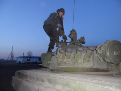

The two photos below show another "Improved T-72A" in Belarus. This particular tank was still in active service, participating in various training exercises.

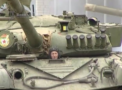
The two photos below show "Improved T-72A" tanks participating in the August 1991 failed coup d'état attempt in Moscow. These vehicles entered service with the 2nd Guards Tamanskaya Motor Rifle Division. The tank in the photo on the left was specifically identified as a T-72A obr. 1983 in the collection of memoirs "Life Given to Tanks".


Currently, tanks with the old 902A system are very rarely encountered in Russia. It is very likely that they were produced in small numbers, and most tanks were instead manufactured with the 902B system in preparation for the installation of Kontakt-1. Upon receiving Kontakt-1, an "Improved T-72A" is converted into a T-72B or T-72B1, depending on whether the tank has the "Svir" missile system installed or just a TPN-3 night vision sight.
60-15-15-15-50 ARMOUR


The design of the upper glacis armour array of the "Improved T-72A" represented the first major design change in the upper glacis armour of all Soviet main battle tanks since the addition of a steel back plate to the STB composite armour of the Object 432 obr. 1964. Instead, the new armour features spaced high hardness steel plates as inserts. In the collection of memoirs "Life Given to Tanks", it is stated by V. D. Tumasov (head of the Department of Armour in UKBTM) that the new armour design was a multilayered array of steel and air, as opposed to composite armour with various fillers. This is corroborated in the book "T-72/T-90: Опыт создания отечественных основных боевых танков" published by the Uralvagonzavod corporation in 2013, where the new armour was described as flat parallel plates with inserts made of high hardness steel. In essence, both describe a multilayered spaced armour array with RHA front and back plates with high hardness steel plate inserts.
The grade of steel is not mentioned in any source. Judging by the low thickness of the plates and the installation method (lack of welding), any high hardness steel with poor weldability can be used. The widespread BT-70 or BT-70Sh high hardness steel grades are the most likely candidates.
Like the upper glacis of a tank with the earlier 60-105-50 armour, the upper glacis of a tank with the "Reflection-1" armour has three anti-ricochet ribs in front of the driver's periscope, with one large rib and two small ribs. This can be seen in the two photos above. Because of this, it is quite difficult to distinguish between a tank with the "Reflection-1" armour and one with 60-105-50 armour. Depending on the context, it may be possible that the lack of a 16mm appliqué armour plate on a post-1984 T-72A tank indicates the presence of the new armour, but this may not be a reliable identifier as it is impossible to confirm that all tanks in the Soviet Army received the appliqué plate during or after 1984.
The thickness of the armour remained the same as that of 60-105-50 design. The omission of STB was ordered by UKBTM Chief Designer V. N. Vendiktov. He specified that the increase in armour mass had to be minimal, and that the protection requirement had to be achieved without using glass textolite. One of the reasons was its cost. Glass textolite is produced using laminated glass mats, and glass mats are the most expensive filler for glass reinforced plastics as stated on page 21 of the book "Стеклотекстолит" ("Glass Textolite"). There were also some safety concerns, as glass fibers are dangerous to inhale.
The new armour was developed at UKBTM with the participation of NII Stali. The institute was engaged in research in all forms of tank armour, including the refining of existing concepts and the exploration of prospective new ideas. NII Stali was involved in work at all three tank design bureaus, in Nizhniy Tagil, Leningrad and Kharkov, but the choice and implementation of the particular type of armour was made at the discretion of the design bureau. One line of research focused on further developing the existing steel-STB-steel armour technology by adding a high hardness steel plate in the middle of the armour array to split the glass textolite layer into two, with a total of five layers in the armour array. This was the option pursued by the LKZ design bureau in Leningrad and by the Malyshev design bureau in Kharkov. In 1985, this type of armour was implemented in the T-64BV and T-80BV, but in different forms. At this point, not one among the three tanks shared the same armour, unlike in the mid 1970's when all three series featured the same 80-105-20 armour developed by NII Stali.
Over the course of the work on the "Reflection-1" project, over thirty mock-ups of different armour configurations were designed, manufactured and tested and 2,500 rounds of ammunition were expended in live fire tests. Multilayered armour arrays with various fillers were considered as well as arrays with no fillers (spaced armour). The objective was to provide protection from M111 as well as from potential KE threats of the future with a simultaneous increase in resistance from HEAT threats.
On the 4th of November 1982, the Ministry of Defence issued order No. 620 to implement the "Reflection-1" project. In accordance with this order, the mass production of T-72A hulls with the new armour began in early 1983 and gradually accelerated. Some of these tanks were paired with the new "reflecting plate" turret, and others were not.
Based on available information, the spaced armour array of the "Improved T-72A" was a limited solution that offered better protection from KE threats but no real improvement in shaped charge protection.


The photo above shows a destroyed T-72 from the first Chechen war. The glacis array of a destroyed "Improved T-72A" is visible down at the bottom half of the left side of the photo. Note that the spaced steel plates are held by spacers identical to the type used in the earlier 80-105-20 and 60-105-20 armour designs. These ensure proper spacing between the plates and are also the sole mounting points for the spaced plates, as they are not welded along the sides, top or bottom edges and there are no discernible supports elsewhere.

The thickness of the internal plates is not known, and the only information that can be gleaned from these photos is that the three plates are spaced equally apart by air gaps of equal size, and the plates all appear to have identical thicknesses.
However, because it is known that the total thickness of the armour array is 215mm, it is reasonable to assume that the upper glacis of the "Improved T-72A" has the same thicknesses for the front plate and back plate (60mm and 50mm respectively) and has a 105mm gap in between. The 105mm gap can be divided into seven parts representing three plates and four air gaps of equal thicknesses. Thus, the plates should be around 15mm thick and the air gaps should be around 15mm in size. The estimated armour array would therefore be 60-15-15-15-50.
In total, this estimated array has 155mm of steel. Compared to earlier armour designs, it is only marginally heavier. The areal density of the armour is 3,248 kg/sq.m, which is quite high, but not significantly higher than the armour of the T-72A with a 16mm appliqué armour plate as that already has an areal density of 3,161 kg/sq.m. The "Improved T-72A" would therefore not have experienced a noticeable weight gain from the change to the new upper glacis armour design. This is congruent with the design objective for the "Reflection-1" project.
In some publications, the upper glacis armour of the tanks seen during the 1986 parade was described as being upgraded with a 20mm appliqué plate, implying that the same 60-105-50 armour was kept but simply reinforced. This claim is self-evidently incorrect. It is most often encountered in English publications from the past two decades, and it may have originated in the article "Танки Т-72: Вчера, Сегодня, Завтра" by Sergey Suvorov, published in the July 2004 issue of the "Техника и Вооружение" magazine.
EFFECT ON KE THREATS
Alone, the combination of a 60mm front plate and 50mm back plate with a 105mm air gap qualifies as spaced armour. As discussed earlier, a two-layer spaced armour of this type achieves an ME coefficient of 1.11 against the 105mm DM13 and 120mm DM13 APFSDS rounds. The three spaced high hardness steel plates serve to further break apart a penetrator before it reaches the back plate, as opposed to the passive resistance offered by the glass textolite interlayer of the old 60-105-50 array.
The interactions between long rod penetrators and spaced armour have been studied extensively, which is quite natural considering that spaced armour is considered the simplest form of multilayered armour. However, from a conceptual standpoint, many spaced armour experiments do not represent the "Reflection-1" armour accurately as there is no thick back plate for the target setup. For example, one study featured in the book "Particular Questions of Terminal Ballistics" 2006 (Частные Вопросы Конечной Баллистики) published by the Bauman Moscow State Technical University on behalf of NII Stali, showed that it was possible to increase the mass efficiency by redistributing the mass of a single homogeneous steel plate into multiple layers in a spaced armour array, but it was found that there were serious limits to the effectiveness of this type of armour.

The two graphs shown below illustrate the difference in the velocity limit of nominal defeat and the change in mass efficiency obtained by splitting homogeneous steel plate. The graph on the left (а), shows the change in the velocity limit of nominal defeat for three tested angles. (1) - 0 degrees; (2) - 30 degrees; (3) - 60 degrees. The graph on the right (б) shows the same, but in terms of percentage, where (1) - 0 degrees; (2) - 30 degrees; (3) - 60 degrees. Additionally, graph (b) shows the change in mass efficiency, where (4) - 0 degrees; (5) - 30 degrees; (6) - 60 degrees.

Splitting a homogeneous steel plate sloped at 60 degrees into two equal layers at the same slope provided a weight saving of around 6%, and splitting it into three equal layers provided the largest weight saving of 13%. Splitting the steel plate into four layers almost completely neutralized the positive effect of spaced armour, and splitting the plate into more than four layers gave a negative effect. While interesting, these findings are mostly irrelevant due to the peculiarities of the experimental setup.
The steep reduction in mass efficiency from the splitting of a homogeneous armour plate into multiple thinner plates below a certain number of layers can be entirely attributed to to the loss of rigidity in the last few plates in the spaced armour array. As discussed before when examining the 80-105-20 armour array, the 20mm back plate had a significantly lower ME coefficient than RHA steel owing to its excessively low thickness and correspondingly low rigidity. A spaced armour array with layers of thin plates that are of a uniform thickness will be able to break up a long rod penetrator quite effectively in the first layers, but the last layers perform poorly as a backing plate. Because of this, the overall efficiency of the array suffers considerably. In this particular experiment, the specific thicknesses of the armour and the caliber of the long rod penetrator tested against it were the two factors that, combined, produced such a result.
An optimal spaced armour design with maximum mass efficiency has an array of thin spaced plates and a thick back plate. This avoids the main issue with a multilayered spaced armour array. Because of this structural factor, the "Reflection-1" armour retains the 50mm back plate of the previous 60-105-50 armour design.
In the same book, a different study is detailed. Different findings were obtained due to a more realistic experimental setup. It was found that high armour obliquity is required for spaced armour to be effective against long rod monobloc penetrators, that increasing the number of plates in a spaced armour array improves its mass efficiency and that increasing the elongation of a long rod penetrator reduces the effectiveness of the spaced armour array. The relevant paragraph is shown below:
"Прирост стойкости двух- и многопреградных структур фиксированной толщины неизбежно падает увеличением длины сердечника БПС в связи с соответствующим увеличением МПР, необходимого для максимально возможного использования эффектов изгиба и разрушения сердечника при пробитии сильно наклоненных преград. На реальном возможных толщинах многопреградных структур следует рассчитывать не более чем на 15% прироста стойкости при воздействии моноблочных вольфрамовых сердечников с удлинением 15...20 (с использованием броневых сталей средней твердости) Этот прирост при больших углах встречи достигается числом преград от трех до пяти, в зависимости от соотношения МПР и общей толщины преграды. При малых углах встречи разнесение преград малоэффективно."
Translation (with notes):
"The increase in the durability of dual and multi-layered structures of a fixed thickness inevitably falls with the increase in the length of the APFSDS penetrator due to the corresponding increase in the MPR [air gap between layers] required for the maximum possible use of the bending and fracture effects of the core when penetrating steeply sloped targets. Given the realistic possible thicknesses of multi-layered structures, one should expect no more than a 15% increase in resistance against monobloc tungsten cores with an elongation [aspect ratio] of 15-20 (using medium hardness armour steels). This increase at large impact angles is achieved with three to five layers, depending on the ratio of the MPR and the total thickness of the array. At small impact angles, incorporating air gaps is ineffective."
In other words, a multi-layered spaced armour array is not more effective than a monolithic homogeneous block of armour at small angles of obliquity and the efficiency of highly angled spaced armour array will decrease when the elongation of a long rod penetrator is increased. Compared to a monolithic homogeneous block when attacked with a tungsten long rod penetrator with an aspect ratio of 15-20, a three to five-layer spaced armour array has a mass efficiency of around 1.15. In addition to this, using high hardness and high strength steels yields further improvements in the efficiency of the armour array:
"Увеличение прочности (твердости) стальных броневых преград при сохранении пластичности приводит к соответствующему повышению противоснарядной стойкости многопреградных структур. Использование броневых сталей повышенной и высокой твердости с пределами текучести 120 ... 130 МПа на структурах, характерных для лобового бронирования танков, обеспечивает дополнительный прирост стойкости 10...15%."
Translation:
"Increasing the strength (hardness) of steel armored barriers while maintaining ductility leads to a corresponding increase in the ballistic resistance of multi-layered structures. The use of high hardness armour steels with yield strengths of 120-130 MPa on structures characteristic for frontal tank armour provides an additional increase in resistance of 10-15%."
An additional nuance of the armour design to consider is the specific combination of thin high hardness plates and small air gaps which is not replicated in many experimental spaced armour targets. For instance, KE munitions in NATO member nations were invariably tested against the NATO Triple Heavy target which was meant to represent the side armour of a Soviet T-10 heavy tank and as such, included large air gaps between the three layers of the target. This is a completely different form of spaced armour with its own distinguishing characteristics. The differences are major enough that in Russian and Chinese textbooks and other specialist literature, this type of spaced armour is referred to as "shielded armour".
On the topic of air gaps, it should be noted that the size of the air gap between densely packed spaced plates such as in the 60-15-15-15-50 array has no direct effect on the integrity of the rod. However, this does not mean that the size of air gaps in tank armour is arbitrary; one of the functions of the air gap is to allow the tip of the rod to ricochet up and away from the plate and to allow the shattered fragments of the tip to be ejected away from the penetration crater, preventing them from contributing to the depth of the penetration. Without a sufficiently large air gap, the fragments have nowhere else to go, so they are pushed into the next armour plate and thus, they can still contribute to armour penetration. The small 15mm air gaps in the armour are sufficiently large to prevent this.
A good example of oblique spaced steel armour arrays can be found in the study "A unified model for long-rod penetration in multiple metallic plates" by S. Chocron et al. A dense pack of six spaced plates was used for the tests, each plate being 19mm thick and sloped at 65 degrees to the vertical plane. Each plate was separated by an air gap of 25.4mm in length and the distance between the last plate and the RHA witness block was 76.2mm. Long rod projectiles were fired at the armour pack at super-ordnance velocity and the depth of penetration into the witness block was recorded.
Super-ordnance velocity was defined as the range velocities of between 1.72 to 1.78 km/s which exceeds the normal muzzle velocity of 105mm and 120mm guns by around Mach 1 and Mach 0.3 respectively. This simulated hypersonic impacts. Hypervelocity penetrators with a velocity of 2.6 km/s were also tested, but the results of these tests have little relevance to us. The lower the impact velocity of the penetrator, the greater the effect of target and penetrator material strength, and the typical impact velocity range for APFSDS fired from 105-120mm guns at 1.5 km is 1,400-1,500 m/s, so the effect of the strength of the RHA and HHS plates in the "Reflection-1" armour array still remains a highly relevant factor in the overall protective capabilities of the armour under normal conditions.
The pretest assumption was that the spaced steel plates would offer the same resistance as the line-of-sight thickness indicated, i.e each 19mm plate was assumed to possess a resistance of 45mm of steel. However, the experiment showed that the estimated penetration depth into the witness block was 40mm less than predicted. It was surmised that repeated impacts and breakouts was the cause of the overprediction, and although it was not explicitly mentioned to be a source of penetration loss, it is worth noting that the 1.78 km/s rod was yawed by 2.34 degrees after passing through the spaced plate array, before it impacted the RHA witness plate. This is consistent with all of the other studies concerning spaced armour. The information regarding the yaw of the penetration was included in a different study, "Pretest Predictions of Long-Rod Interactions With Armor Technology Targets".
As the illustration below shows, the pressure spikes at the moment of impact with a spaced plate and falls rapidly as the rod passes through the physical thickness of the plate. After perforating the plate, the pressure drops down to zero as the rod travels into the air gap before spiking again as the next plate is struck.

The inability of the penetrator rod to achieve quasi-steady state penetration through spaced plates results in a reduction in the efficiency of the rod.
According to the experiments, it was deduced that the deformed and fractured tip of the penetrator is a result of structural failure from large stresses, so it was considered to no longer be a part of the rod. For all intents and purposes, the tip was therefore considered to be incapable of contributing to the penetration of the rod, so it was discarded after the perforation of each spaced plate to simulate the detachment of the tip. To simulate the discarded tip, lengths of 1.5 D or 1.8 D were subtracted from the rod, and a loss of 1.8 D was found to generally agree with the results of the super-ordnance penetrator (1.72 km/s) but not the hypervelocity penetrator (2.6 km/s). The analytic model for the hypervelocity penetrator would require a length reduction of as much as 2.0 D to agree with the experimental results. To supplement this, it is stated on page 250 in "Particular Questions of Terminal Ballistics" 2006 (Частные Вопросы Конечной Баллистики) that the length of the rod broken off due to breakout effects for plates at a high obliquity was equal to 1.5 times the LOS thickness of the plate, regardless of the hardness of the plate.
In total, a significant amount of penetrator material is lost during the impact and breakout phases, which allows a spaced thin plate to reduce the penetration power of a long rod penetrator by more than the LOS thickness of the plate implies. Because of this, an array of multiple thin spaced plates with small air gaps can have a positive mass efficiency.
From this, it is easy to see the advantage of multiple oblique spaced plates of high hardness steel. These results are supported by the findings in studies such as "Oblique Impact of Elongated Projectiles on Massive Targets" by Veldanov et al. and "Ricochet of a tungsten heavy alloy long-rod projectile from deformable steel plates" by Woong Lee et al., and others. Of course, it should not be forgotten that all of the same impact and breakout effects apply to the heavy front plate of the array as it can contribute to the effectiveness of the spaced plates by removing and deforms the tip of long rod penetrators, conditioning them for defeat by the spaced plates.
All of these phenomena can be seen in the image below where a two-layer spaced armour target with a small air gap is perforated by a long rod penetrator with a high aspect ratio. The image is a composite of several X-ray photos at different points in time. After passing through both plates, the rod is highly fragmented and the tip is completely missing, having been destroyed as it was deflected off the surfaces of the first and second spaced plates.

The two waves of penetrator ejecta on the surfaces of the two plates show the large amount of penetrator material removed during the impact phase with the two plates. Furthermore, the amount of ejecta visible on the second plate is clearly more than the ejecta from the first plate, showing that the destruction of the original tip on the surface of the first plate reduced the efficiency of the rod during the following impact with the second plate.
As mentioned before, six spaced plates were used in the experimental array, each 19mm thick and spaced an inch apart from each other (25.4mm). The witness block was spaced behind the last plate at a distance of 76.2mm and simulated a semi-infinite target. The entire array was angled at 65 degrees and the total LOS thickness was 270mm. The LOS penetration of the spaced plate array including the penetration depth into the witness block amounted to a total of only 414mm. Compared to the penetration depth of 524mm recorded for the finite thickness plate at a normal impact angle, the difference amounts 110mm RHA. Therefore, the spaced armour array is worth 110mm more armour than its own LOS thickness, implicitly indicating a mass efficiency of 1.26 for the spaced steel plate array. This is despite the fact that long rod penetrators are known to penetrate a greater thickness of sloped armour plate than flat armour plate.
Alone, the combination of a 60mm front plate and 50mm back plate with a 105mm air gap qualifies as spaced armour. As discussed earlier, a two-layer spaced armour of this type achieves an ME coefficient of 1.11 against the 105mm DM13 and 120mm DM13 APFSDS rounds. The three spaced high hardness steel plates serve to further break apart a penetrator before it reaches the back plate, as opposed to the passive resistance offered by the glass textolite interlayer of the old 60-105-50 array.
The interactions between long rod penetrators and spaced armour have been studied extensively, which is quite natural considering that spaced armour is considered the simplest form of multilayered armour. However, from a conceptual standpoint, many spaced armour experiments do not represent the "Reflection-1" armour accurately as there is no thick back plate for the target setup. For example, one study featured in the book "Particular Questions of Terminal Ballistics" 2006 (Частные Вопросы Конечной Баллистики) published by the Bauman Moscow State Technical University on behalf of NII Stali, showed that it was possible to increase the mass efficiency by redistributing the mass of a single homogeneous steel plate into multiple layers in a spaced armour array, but it was found that there were serious limits to the effectiveness of this type of armour.

The two graphs shown below illustrate the difference in the velocity limit of nominal defeat and the change in mass efficiency obtained by splitting homogeneous steel plate. The graph on the left (а), shows the change in the velocity limit of nominal defeat for three tested angles. (1) - 0 degrees; (2) - 30 degrees; (3) - 60 degrees. The graph on the right (б) shows the same, but in terms of percentage, where (1) - 0 degrees; (2) - 30 degrees; (3) - 60 degrees. Additionally, graph (b) shows the change in mass efficiency, where (4) - 0 degrees; (5) - 30 degrees; (6) - 60 degrees.

Splitting a homogeneous steel plate sloped at 60 degrees into two equal layers at the same slope provided a weight saving of around 6%, and splitting it into three equal layers provided the largest weight saving of 13%. Splitting the steel plate into four layers almost completely neutralized the positive effect of spaced armour, and splitting the plate into more than four layers gave a negative effect. While interesting, these findings are mostly irrelevant due to the peculiarities of the experimental setup.
The steep reduction in mass efficiency from the splitting of a homogeneous armour plate into multiple thinner plates below a certain number of layers can be entirely attributed to to the loss of rigidity in the last few plates in the spaced armour array. As discussed before when examining the 80-105-20 armour array, the 20mm back plate had a significantly lower ME coefficient than RHA steel owing to its excessively low thickness and correspondingly low rigidity. A spaced armour array with layers of thin plates that are of a uniform thickness will be able to break up a long rod penetrator quite effectively in the first layers, but the last layers perform poorly as a backing plate. Because of this, the overall efficiency of the array suffers considerably. In this particular experiment, the specific thicknesses of the armour and the caliber of the long rod penetrator tested against it were the two factors that, combined, produced such a result.
An optimal spaced armour design with maximum mass efficiency has an array of thin spaced plates and a thick back plate. This avoids the main issue with a multilayered spaced armour array. Because of this structural factor, the "Reflection-1" armour retains the 50mm back plate of the previous 60-105-50 armour design.
In the same book, a different study is detailed. Different findings were obtained due to a more realistic experimental setup. It was found that high armour obliquity is required for spaced armour to be effective against long rod monobloc penetrators, that increasing the number of plates in a spaced armour array improves its mass efficiency and that increasing the elongation of a long rod penetrator reduces the effectiveness of the spaced armour array. The relevant paragraph is shown below:
"The increase in the durability of dual and multi-layered structures of a fixed thickness inevitably falls with the increase in the length of the APFSDS penetrator due to the corresponding increase in the MPR [air gap between layers] required for the maximum possible use of the bending and fracture effects of the core when penetrating steeply sloped targets. Given the realistic possible thicknesses of multi-layered structures, one should expect no more than a 15% increase in resistance against monobloc tungsten cores with an elongation [aspect ratio] of 15-20 (using medium hardness armour steels). This increase at large impact angles is achieved with three to five layers, depending on the ratio of the MPR and the total thickness of the array. At small impact angles, incorporating air gaps is ineffective."
In other words, a multi-layered spaced armour array is not more effective than a monolithic homogeneous block of armour at small angles of obliquity and the efficiency of highly angled spaced armour array will decrease when the elongation of a long rod penetrator is increased. Compared to a monolithic homogeneous block when attacked with a tungsten long rod penetrator with an aspect ratio of 15-20, a three to five-layer spaced armour array has a mass efficiency of around 1.15. In addition to this, using high hardness and high strength steels yields further improvements in the efficiency of the armour array:
"Увеличение прочности (твердости) стальных броневых преград при сохранении пластичности приводит к соответствующему повышению противоснарядной стойкости многопреградных структур. Использование броневых сталей повышенной и высокой твердости с пределами текучести 120 ... 130 МПа на структурах, характерных для лобового бронирования танков, обеспечивает дополнительный прирост стойкости 10...15%."
Translation:
"Increasing the strength (hardness) of steel armored barriers while maintaining ductility leads to a corresponding increase in the ballistic resistance of multi-layered structures. The use of high hardness armour steels with yield strengths of 120-130 MPa on structures characteristic for frontal tank armour provides an additional increase in resistance of 10-15%."
An additional nuance of the armour design to consider is the specific combination of thin high hardness plates and small air gaps which is not replicated in many experimental spaced armour targets. For instance, KE munitions in NATO member nations were invariably tested against the NATO Triple Heavy target which was meant to represent the side armour of a Soviet T-10 heavy tank and as such, included large air gaps between the three layers of the target. This is a completely different form of spaced armour with its own distinguishing characteristics. The differences are major enough that in Russian and Chinese textbooks and other specialist literature, this type of spaced armour is referred to as "shielded armour".
On the topic of air gaps, it should be noted that the size of the air gap between densely packed spaced plates such as in the 60-15-15-15-50 array has no direct effect on the integrity of the rod. However, this does not mean that the size of air gaps in tank armour is arbitrary; one of the functions of the air gap is to allow the tip of the rod to ricochet up and away from the plate and to allow the shattered fragments of the tip to be ejected away from the penetration crater, preventing them from contributing to the depth of the penetration. Without a sufficiently large air gap, the fragments have nowhere else to go, so they are pushed into the next armour plate and thus, they can still contribute to armour penetration. The small 15mm air gaps in the armour are sufficiently large to prevent this.
A good example of oblique spaced steel armour arrays can be found in the study "A unified model for long-rod penetration in multiple metallic plates" by S. Chocron et al. A dense pack of six spaced plates was used for the tests, each plate being 19mm thick and sloped at 65 degrees to the vertical plane. Each plate was separated by an air gap of 25.4mm in length and the distance between the last plate and the RHA witness block was 76.2mm. Long rod projectiles were fired at the armour pack at super-ordnance velocity and the depth of penetration into the witness block was recorded.
Super-ordnance velocity was defined as the range velocities of between 1.72 to 1.78 km/s which exceeds the normal muzzle velocity of 105mm and 120mm guns by around Mach 1 and Mach 0.3 respectively. This simulated hypersonic impacts. Hypervelocity penetrators with a velocity of 2.6 km/s were also tested, but the results of these tests have little relevance to us. The lower the impact velocity of the penetrator, the greater the effect of target and penetrator material strength, and the typical impact velocity range for APFSDS fired from 105-120mm guns at 1.5 km is 1,400-1,500 m/s, so the effect of the strength of the RHA and HHS plates in the "Reflection-1" armour array still remains a highly relevant factor in the overall protective capabilities of the armour under normal conditions.
The pretest assumption was that the spaced steel plates would offer the same resistance as the line-of-sight thickness indicated, i.e each 19mm plate was assumed to possess a resistance of 45mm of steel. However, the experiment showed that the estimated penetration depth into the witness block was 40mm less than predicted. It was surmised that repeated impacts and breakouts was the cause of the overprediction, and although it was not explicitly mentioned to be a source of penetration loss, it is worth noting that the 1.78 km/s rod was yawed by 2.34 degrees after passing through the spaced plate array, before it impacted the RHA witness plate. This is consistent with all of the other studies concerning spaced armour. The information regarding the yaw of the penetration was included in a different study, "Pretest Predictions of Long-Rod Interactions With Armor Technology Targets".
As the illustration below shows, the pressure spikes at the moment of impact with a spaced plate and falls rapidly as the rod passes through the physical thickness of the plate. After perforating the plate, the pressure drops down to zero as the rod travels into the air gap before spiking again as the next plate is struck.

The inability of the penetrator rod to achieve quasi-steady state penetration through spaced plates results in a reduction in the efficiency of the rod.
According to the experiments, it was deduced that the deformed and fractured tip of the penetrator is a result of structural failure from large stresses, so it was considered to no longer be a part of the rod. For all intents and purposes, the tip was therefore considered to be incapable of contributing to the penetration of the rod, so it was discarded after the perforation of each spaced plate to simulate the detachment of the tip. To simulate the discarded tip, lengths of 1.5 D or 1.8 D were subtracted from the rod, and a loss of 1.8 D was found to generally agree with the results of the super-ordnance penetrator (1.72 km/s) but not the hypervelocity penetrator (2.6 km/s). The analytic model for the hypervelocity penetrator would require a length reduction of as much as 2.0 D to agree with the experimental results. To supplement this, it is stated on page 250 in "Particular Questions of Terminal Ballistics" 2006 (Частные Вопросы Конечной Баллистики) that the length of the rod broken off due to breakout effects for plates at a high obliquity was equal to 1.5 times the LOS thickness of the plate, regardless of the hardness of the plate.
From this, it is easy to see the advantage of multiple oblique spaced plates of high hardness steel. These results are supported by the findings in studies such as "Oblique Impact of Elongated Projectiles on Massive Targets" by Veldanov et al. and "Ricochet of a tungsten heavy alloy long-rod projectile from deformable steel plates" by Woong Lee et al., and others. Of course, it should not be forgotten that all of the same impact and breakout effects apply to the heavy front plate of the array as it can contribute to the effectiveness of the spaced plates by removing and deforms the tip of long rod penetrators, conditioning them for defeat by the spaced plates.
In total, a significant amount of penetrator material is lost during the impact and breakout phases, which allows a spaced thin plate to reduce the penetration power of a long rod penetrator by more than the LOS thickness of the plate implies. Because of this, an array of multiple thin spaced plates with small air gaps can have a positive mass efficiency.
From this, it is easy to see the advantage of multiple oblique spaced plates of high hardness steel. These results are supported by the findings in studies such as "Oblique Impact of Elongated Projectiles on Massive Targets" by Veldanov et al. and "Ricochet of a tungsten heavy alloy long-rod projectile from deformable steel plates" by Woong Lee et al., and others. Of course, it should not be forgotten that all of the same impact and breakout effects apply to the heavy front plate of the array as it can contribute to the effectiveness of the spaced plates by removing and deforms the tip of long rod penetrators, conditioning them for defeat by the spaced plates.
All of these phenomena can be seen in the image below where a two-layer spaced armour target with a small air gap is perforated by a long rod penetrator with a high aspect ratio. The image is a composite of several X-ray photos at different points in time. After passing through both plates, the rod is highly fragmented and the tip is completely missing, having been destroyed as it was deflected off the surfaces of the first and second spaced plates.

The two waves of penetrator ejecta on the surfaces of the two plates show the large amount of penetrator material removed during the impact phase with the two plates. Furthermore, the amount of ejecta visible on the second plate is clearly more than the ejecta from the first plate, showing that the destruction of the original tip on the surface of the first plate reduced the efficiency of the rod during the following impact with the second plate.
As mentioned before, six spaced plates were used in the experimental array, each 19mm thick and spaced an inch apart from each other (25.4mm). The witness block was spaced behind the last plate at a distance of 76.2mm and simulated a semi-infinite target. The entire array was angled at 65 degrees and the total LOS thickness was 270mm. The LOS penetration of the spaced plate array including the penetration depth into the witness block amounted to a total of only 414mm. Compared to the penetration depth of 524mm recorded for the finite thickness plate at a normal impact angle, the difference amounts 110mm RHA. Therefore, the spaced armour array is worth 110mm more armour than its own LOS thickness, implicitly indicating a mass efficiency of 1.26 for the spaced steel plate array. This is despite the fact that long rod penetrators are known to penetrate a greater thickness of sloped armour plate than flat armour plate.
KE PROTECTION
According to an article published by Andrei Tarasenko, the first version of the T-72B hull armour (referring to the "Improved T-72A" from 1984) was 20% more effective than a homogeneous plate by mass, so the ME coefficient is 1.2. In a separate article, the armour is stated to have an effective thickness of 490mm RHA. However, the standard of armour defeat used to determine this coefficient is not known. As such, this effective thickness figure could refer to either nominal defeat or initial perforation. More likely, it refers to the latter. Aside from these articles by Tarasenko, there are no other sources that directly divulge the effective thickness of this armour.
According to an article published by Andrei Tarasenko, the first version of the T-72B hull armour (referring to the "Improved T-72A" from 1984) was 20% more effective than a homogeneous plate by mass, so the ME coefficient is 1.2. In a separate article, the armour is stated to have an effective thickness of 490mm RHA. However, the standard of armour defeat used to determine this coefficient is not known. As such, this effective thickness figure could refer to either nominal defeat or initial perforation. More likely, it refers to the latter. Aside from these articles by Tarasenko, there are no other sources that directly divulge the effective thickness of this armour.
EFFECT ON SHAPED CHARGES
Against shaped charges, the main consequence of switching from a steel-STB-steel composite to a spaced steel armour array was the change in the operating principle of the armour. The "Reflection-1" armour was still a completely passive system, but the interstitial space between the front plate and back plate no longer serves to only absorb the kinetic energy of the SCJ but also functions as additional disruptive elements.
However, this does not imply that the armour has a higher ME compared to steel-STB-steel composite against shaped charges. On the contrary, this type of spaced armour is generally inferior. This may only be somewhat offset by the fact that the "Reflection-1" armour is only slightly heavier than the 16-60-105-50 armour.
As mentioned before, increasing the hardness of the steel front plate leads to a reduction in the overall efficiency of the armour array as it reduces the energy absorption capacity of the material and renders it less effective at disrupting the cohesiveness of an SCJ. However, the high hardness of the internal spaced steel plates has no significant effect. The combination of a 60mm RHA front plate and high hardness 15mm spaced plates is therefore not problematic.
In a study presented in a Chinese textbook on tank armour, a form of spaced armour closely resembling that of the "Reflection-1" design was experimented upon. The primary finding is that the obliquity of the spaced armour array has little to no effect on its effectiveness. Moreover, it was found that the penetration of the shaped charge into the spaced multilayer target is reduced by 15% compared to a monolithic steel target, i.e. the final penetration is 85% of the amount in a monolithic steel target. The reciprocal of 0.85 is calculated to find the ME coefficient: 1.176. The total volume of the holes created in each spaced plate is larger than the volume of the penetration crater created in a monolithic steel target, indicated for the spaced target, a smaller portion of the jet energy was spent increasing the depth of the penetration channel.
Against shaped charges, the main consequence of switching from a steel-STB-steel composite to a spaced steel armour array was the change in the operating principle of the armour. The "Reflection-1" armour was still a completely passive system, but the interstitial space between the front plate and back plate no longer serves to only absorb the kinetic energy of the SCJ but also functions as additional disruptive elements.
However, this does not imply that the armour has a higher ME compared to steel-STB-steel composite against shaped charges. On the contrary, this type of spaced armour is generally inferior. This may only be somewhat offset by the fact that the "Reflection-1" armour is only slightly heavier than the 16-60-105-50 armour.
However, this does not imply that the armour has a higher ME compared to steel-STB-steel composite against shaped charges. On the contrary, this type of spaced armour is generally inferior. This may only be somewhat offset by the fact that the "Reflection-1" armour is only slightly heavier than the 16-60-105-50 armour.
As mentioned before, increasing the hardness of the steel front plate leads to a reduction in the overall efficiency of the armour array as it reduces the energy absorption capacity of the material and renders it less effective at disrupting the cohesiveness of an SCJ. However, the high hardness of the internal spaced steel plates has no significant effect. The combination of a 60mm RHA front plate and high hardness 15mm spaced plates is therefore not problematic.
In a study presented in a Chinese textbook on tank armour, a form of spaced armour closely resembling that of the "Reflection-1" design was experimented upon. The primary finding is that the obliquity of the spaced armour array has little to no effect on its effectiveness. Moreover, it was found that the penetration of the shaped charge into the spaced multilayer target is reduced by 15% compared to a monolithic steel target, i.e. the final penetration is 85% of the amount in a monolithic steel target. The reciprocal of 0.85 is calculated to find the ME coefficient: 1.176. The total volume of the holes created in each spaced plate is larger than the volume of the penetration crater created in a monolithic steel target, indicated for the spaced target, a smaller portion of the jet energy was spent increasing the depth of the penetration channel.
In a study presented in a Chinese textbook on tank armour, a form of spaced armour closely resembling that of the "Reflection-1" design was experimented upon. The primary finding is that the obliquity of the spaced armour array has little to no effect on its effectiveness. Moreover, it was found that the penetration of the shaped charge into the spaced multilayer target is reduced by 15% compared to a monolithic steel target, i.e. the final penetration is 85% of the amount in a monolithic steel target. The reciprocal of 0.85 is calculated to find the ME coefficient: 1.176. The total volume of the holes created in each spaced plate is larger than the volume of the penetration crater created in a monolithic steel target, indicated for the spaced target, a smaller portion of the jet energy was spent increasing the depth of the penetration channel.

However, despite the close resemblance of the target used in the experiment to the spaced plates in the "Reflection-1" armour, it is not possible to directly apply the findings of this study because the SCJ is not disrupted before it encounters the target. In the "Reflection-1" armour, the front plate is still thick enough to disrupt and scatter the jet of a shaped charge warhead, so the penetration of the jet will not increase due to jet stretching in the air gaps of the spaced armour array, and the penetration efficiency is lower as a whole. This resolves the issue of spaced armour acting as additional standoff for a shaped charge warhead, and it enhances the disruptive effect of the internal spaced plates. As such, it is only possible to conclude that the ME coefficient of the internal spaced plates is more than 1.176, and nothing else.
It is important to note that in the 80-105-20 and 60-105-50 armour designs, the steel back plate has an ME coefficient of 1.13 because it encounters the SCJ only after it has been scattered by perforating the steel front plate. By applying this ME coefficient to the spaced plates and the back plate in the "Reflection-1" array, it is estimated that these layers have an ME coefficient of ~1.33. The overall ME coefficient of the entire armour array is therefore 1.2. This approach is probably far too simple to have yielded an accurate calculation.
However, it is stated in page 286 of the textbook "Particular Questions of Terminal Ballistics" that a multi-layered NERA armour design is 40% more effective than monolithic steel of the same weight against shaped charges and 10-23% more effective than multi-layered spaced steel armour of the same weight. Based on this, it can be surmised that spaced steel armour would have a mass efficiency of 1.14 to 1.27 compared to homogeneous steel armour. The midpoint of these figures, 1.2, is coincidentally the same as the figure obtained earlier.
HEAT PROTECTION
Applying the ME coefficient of 1.2, the "Reflection-1" armour would have an effective thickness of 496mm RHA, which makes it essentially equivalent to the 500mm RHA effective thickness of the basic T-72A. This figure is completely congruent with the general requirement for the "Reflection-1" armour to be a significant improvement over the earlier 60-105-50 armour design in terms of resistance to KE threats and to not be inferior in terms of resistance to HEAT threats.
The lack of an improvement in shaped charge protection was not considered a significant shortcoming of the armour as the task of countering the existing and upcoming ATGM systems in NATO was left to be handled by "Kontakt-1" ERA. While an improvement in the base armour protection was certainly desirable, the magnitude of the improvement required to make a difference against the new generation of ATGM systems (with a penetration of up to 900mm RHA) required the application of a completely new type of armour with an extremely high mass efficiency. This was, in essence, fulfilled by ERA.
60-10-10-20-20-50 ARMOUR
The upper glacis armour of the T-72B was a further development of the "Reflection-1" project, which had been implemented on T-72 tanks since 1983. The lighter "Reflection-1" armour (60-15-15-15-50) that was used for the "Improved T-72A" tanks from 1983 and 1984 yielded a very modest gain in weight compared to the 16-60-105-50 armour array, but due to the higher efficiency against KE threats, the effect is that the new armour array approaches or reaches 500mm RHA in effective thickness, which is very good. This was sufficient protection against the 105mm gun threat, but providing security from the new APFSDS ammunition developed for the British L11 and L30 rifled 120mm guns and the new 120mm gun observed on the new German Leopard 2 tank was a more difficult task that required a further gain in protection value, which necessitated a gain in armour mass.
The new armour retained a 60mm front plate and a 50mm back plate, but the size of the interstitial space was increased to 110mm. In it, there were two 10mm high hardness steel plates and two 20mm high hardness steel plates, each separated by 10mm air gaps. The overall array scheme of the array is 60-10-10-20-20-50.
Like the earlier upper glacis armour designs, there are three anti-ricochet ribs in front of the driver's periscope. Externally, there seems to be no identification aid that can be used to distinguish this armour from the "Reflection-1" armour.
The photo below shows the exposed glacis armour of a T-72B3 that its idler mount ripped off due to an accident during the 2015 Tank Biathlon. Although the camera angle is not ideal, it can be seen that the layout of the internal spaced plates match the description. The uniform coat of surface rust indicates that these are simply steel plates and not NERA panels.

The two images below show another T-72B that was involved in an accident severe enough to rip off the idler mount, thus exposing the same part of the upper glacis armour.


Again, it can be clearly seen that the spaced steel plates are not welded to the side hull armour plate by looking at the photo below. The spacing between the plates is maintained by metal spacing brackets similar to the type used in the "Reflection-1" armour, but they are removed in the photo below. This explains why the space between the plates is uneven and some of the plates are in contact with each other, whereas the plates of the damaged T-72B3 seen in the photo above clearly show uniform spacing between the plates.


It is likely that BT-70Sh high hardness ESR steel was used, as it is treated a hardness of around 534 BHN when produced in thin plates and is readily weldable. However, the spaced steel plates of the armour arrays described for the "Improved T-72A" and T-72B obr. 1985 variants are not secured to the side hull plates by welding but are suspended by spacers. This means that welding is not an issue, so high hardness steels with poor weldability can be used without structural issues. However, without having clear answers regarding the specific grade of steel used for the spaced plates is used in the T-72B, it is perhaps safer to work under a conservative estimate is that BTK-1Sh steel was used.
The total thickness of this array is 220mm which is only 5mm more than the 60-105-50 array of the T-72A and 6mm less than the upgraded 16-60-105-50 array, but the thickness of steel in the array is increased from 110-126mm to 170mm. The total thickness of steel is also greater than in the "Reflection-1" array. At the constructional 68-degree angle of the upper glacis, the physical LOS thickness of steel in the array is 454mm.
The areal density is 3,562 kg/sq.m. From its areal density alone, the armour array would be similar to the armour of the Leopard 2 (~3,500 kg/sq.m), but the actual effective armour value requires the mass efficiency to be known. For instance, since the Leopard 2 is known to use NERA armour, it must have a higher mass efficiency against HEAT threats compared to the spaced steel armour of the T-72B, but it is also known that early NERA designs were largely ineffective against long rod penetrators so the armour may be less effective than the T-72B against KE threats. Knowing the areal densities, the comparative thicknesses of the armour does not matter that much as it is obvious that the thicker array is simply filled with more air than the thinner array.
EFFECT ON APFSDS
As a further development on the "Reflection-1" concept, the heavier and more complex 60-10-10-20-20-50 armour works under the same operating principles against long rod penetrators, differing only in the greater number of layers and the increased complexity. An increase in mass efficiency is expected from this, but the extent of the improvement is not well understood. It is only safe to assume that the ME coefficient of the armour is somewhat above 1.2.
KE PROTECTION
In the memoirs "Life Given to Tanks" dedicated to the UKBTM chief designer V.N Venediktov, published in 2010, G. A. Kheifits, a leading specialist in the Department of Armour at UKBTM who was appointed to the State Commission for testing the T-72B tank, describes the live fire tests against mock ups of the T-72B upper glacis and other experimental armour designs developed by the UKBTM design bureau that took place at the proving grounds of the Main Missile and Artillery Directorate (GRAU) in Donguz (in the Southern Urals). At the same time, various armour designs developed by the LKZ design bureau were also being tested at the same proving grounds, including a mock up of the T-80BV upper glacis. The tests were carried out with the 125mm 3BM-32 "Vant" monobloc DU long rod APFSDS ammunition, which was the newest ammunition of its type available in the Soviet Army in 1985.
According to Kheifits, the tests of the T-72B armour designed by UKBTM were successful. Even after increasing the amount of propellant to launch the "Vant" round at its maximum permissible velocity, it was not possible to break through the armour. On the other hand, the armour designed by LKZ was perforated by "Vant" when fired from a standard propellant charge.
According to Kheifits, the tests of the T-72B armour designed by UKBTM were successful. Even after increasing the amount of propellant to launch the "Vant" round at its maximum permissible velocity, it was not possible to break through the armour. On the other hand, the armour designed by LKZ was perforated by "Vant" when fired from a standard propellant charge.
Using the Lanz-Odermatt equation, the perforation limit of 3BM32 "Vant" at its muzzle velocity of 1,710 m/s is calculated to be 192mm at 68 degrees (~513mm LOS), with the target being medium hardness RHA (270 BHN). To convert from initial perforation to nominal defeat, a physical thickness of 10mm is added, translating to an effective thickness figure of 540mm. In other words, to resist 3BM32 at its muzzle velocity, the effective thickness of the 60-10-10-20-20-50 armour must equivalent to around 540mm RHA. With the armour having the same weight as 454mm of steel, this implies that the mass efficiency coefficient of the armour is only 1.18 which is less than the 1.2 coefficient of the "Reflection-1" array.
The so-called "maximum permissible velocity" is assumed to be the muzzle velocity of "Vant" at a charge temperature of +40°C, which is listed as the maximum temperature in a NIMI (Research Institute of the Machine Industry) catalogue. With 12/7 V/A propellant, the difference in muzzle velocity at 15°C and 40°C is +2.5%. The maximum permissible velocity is therefore around 1,753 m/s. At this velocity, the perforation limit is calculated to be 195mm RHA at 68 degrees (~522mm LOS). Converting to nominal defeat, the effective thickness of the armour would be around 550mm RHA.
The so-called "maximum permissible velocity" is assumed to be the muzzle velocity of "Vant" at a charge temperature of +40°C, which is listed as the maximum temperature in a NIMI (Research Institute of the Machine Industry) catalogue. With 12/7 V/A propellant, the difference in muzzle velocity at 15°C and 40°C is +2.5%. The maximum permissible velocity is therefore around 1,753 m/s. At this velocity, the perforation limit is calculated to be 195mm RHA at 68 degrees (~522mm LOS). Converting to nominal defeat, the effective thickness of the armour would be around 550mm RHA.
Based on this, the ME coefficient of the armour is 1.2, which is not higher than the "Reflection-1" array. This is not consistent with the increased complexity of the armour array, but nevertheless, it is supported by some evidence.
According to Swedish trials, 120mm DM33 perforates a LOS thickness of 530mm RHA at 200 meters and a LOS thickness of 470mm RHA at 2,000 meters, converted from its perforation limits on armour sloped at 60 degrees. Based on this, DM33 should perforate a LOS thickness of 565mm RHA and 500mm RHA against armour set at 68 degrees at 200 meters and 2,000 meters respectively. Based on these figures alone, the 60-10-10-20-20-50 armour is nominally capable of resisting DM33 at a range of around 1,000 meters.
Against armour set at 68 degrees, M829 perforates a LOS thickness of 552mm RHA at its muzzle velocity and a LOS thickness of 522mm RHA at 2,000 meters. From this, it can be estimated that the 60-10-10-20-20-50 armour is nominally capable of resisting M829 at a range of around 500 meters and above.
The 60-10-10-20-20-50 armour is 1.35 times heavier than the 80-105-20 armour used in the T-72 Ural and T-72 Ural-1. However, thanks to a substantial improvement in mass efficiency, the calculated effective thickness is 1.83 times is greater than the 80-105-20 armour.
The 60-10-10-20-20-50 armour is 1.35 times heavier than the 80-105-20 armour used in the T-72 Ural and T-72 Ural-1. However, thanks to a substantial improvement in mass efficiency, the calculated effective thickness is 1.83 times is greater than the 80-105-20 armour.
EFFECT ON SHAPED CHARGES
Having the same 60mm front plate as the "Reflection-1" armour and a similar spaced plate array, it is reasonable to assume that it has the same mass efficiency as its parent design. However, due to the smaller air gaps between each spaced plate, the armour may offer better protection thanks to the "lip" effect.
The spaced steel armour array shown below, taken from the research paper "Pancerze Pasywne" (Passive Armour), shows the penetration channel of a densely packed spaced plate array that exhibits the "lip" effect.

When testing this type of armour, it was observed that additional protection value was provided from the interference of a shaped charge jet by the "lips" formed at the edges of the perforated plates, which are deflected from the neighbouring plate and into the path of the penetrator. It was noted that only slightly better results were observed at high angles of obliquity, and that an improvement can be gained by packing more spaced plates in a smaller space.
Due to the denser layout of of spaced plates inside the 60-10-10-20-20-50 armour compared to the "Reflection-1" armour, the "lip" effect further enhances the mass efficiency offered by the new armour design against shaped charges. As such, it is reasonable to expect the mass efficiency of the armour to exceed 1.2.
Due to the denser layout of of spaced plates inside the 60-10-10-20-20-50 armour compared to the "Reflection-1" armour, the "lip" effect further enhances the mass efficiency offered by the new armour design against shaped charges. As such, it is reasonable to expect the mass efficiency of the armour to exceed 1.2.
HEAT PROTECTION
Based on the available information, the armour would be sufficient against practically all handheld antitank weapons, tank-fired HEAT shells, as well as most older anti-tank missiles like the TOW (430mm penetration), MILAN (530mm penetration), and the domestic 9M113 "Konkurs" missile (550mm penetration) but only by a small margin.
Due to the installation of Kontakt-1 as standard equipment on the T-72B, the upper glacis became completely invulnerable to all of these missiles, and any other single-charge HEAT warhead. The use of tandem warheads would negate Kontakt-1 to a large extent, so missiles like the TOW-2A would be a serious threat to the upper glacis armour.
"REFLECTING PLATE" TURRET


Reflecting plate armour was developed and integrated with a new turret as a result of the collaboration between NII Stali and UVZ. By April 1980, UVZ engineers began undertaking the preparation work for the production of the new turret. In September 1982, the new 172.10.077SB (172.10.077СБ) turret with reflecting plate armour inserts entered low rate production. In early 1983, mass production of the 172.10.077SB turret began. Throughout the course of the year, the 172.10.077SB turret gradually replaced the 172.10.073SB turret with "Kvartz" inserts for new-production T-72A tanks on the assembly line at Uralvagonzavod. By the 1st of January 1984, all new-production T-72A tanks were built with the new turret.


All tanks produced from the 1st of January 1984 until the 23rd of January 1985 had this turret, when the Object 184 and Object 184-1 officially entered service as the T-72B and T-72B1. T-72B tanks produced in 1985 and after had slightly modified turrets that were assigned the code 172.10.100SB. Some differences related to the armour may exist between the 077 and 100 turrets, but they are unconfirmed. For simplicity, they are referred to as "reflecting plate" turrets.
The article "Положение в Отечественном Танкостроении: Правда и вымыслы" published in the November 2006 issue of the Russian magazine "Журнал Техника и Вооружение" mentions in page 14 that the protection of the 1985 edition of the T-72B is equivalent to more than 550mm against a KE projectile. This is probably a general descriptor that applies for the frontal arc of the tank including both the turret and the hull, but it is widely accepted that the turret of the T-72B is the stronger of the two, for reasons which we will see later on. Andrei Tarasenko reports that the turret of the T-72B is equivalent to 540mm RHA at a side angle of 30 degrees.
The turret - dubbed "Super Dolly Parton" by American observers - retains the same general shape of previous turret models but features thicker and heavier turret cheek armour. The most obvious visual trait of the turret is the prominent cut under each turret cheek. As on the "Kvartz" turret, the cuts ensure that the driver's hatch can be opened even when a cheek is overhanging it.

Each turret cheek features a large cavity where reflecting plate panels are installed and secured. Compared to the earlier turret design with a "Kvartz" filler, the thickness of the cast steel walls of the armour cavity decreased considerably, giving the composite armour a greater share of the weight. The size of the turret cheeks is fully apparent in the photo below, as is the size of the weakened zone created by the cut in the turret to accommodate the gun cradle trunnions and the coaxial machine gun.


The use of NERA in the turret was inline with contemporary developments in composite armour technology within the Soviet Union and abroad. At the time when it first began to be used in the Soviet Army on late model T-72A tanks in the 1983-1984 time frame, a different form of NERA was being incorporated into T-62M and T-55AM tanks in the form of "metal-polymer" armour which consisted of steel plates suspended in polyurethane. Abroad, all of the next-generation tanks created by the three major NATO military powers - the United States, West Germany and U.K with the M1 Abrams, Leopard 2 and Challenger 1 respectively - used bulging plate-type NERA technology extensively.
The Russian terminology for non-explosive reactive armour is the same as in the West, being labeled as a "non-explosive dynamic armour" as opposed to "explosive dynamic armour" which is better known as explosive reactive armour in English speaking countries. The operating principles of the two types of "dynamic armour" are recognized as the same, except that one is simply more energetic than the other. The drawing on the left below describes the action of ERA, and the drawing on the right below shows the action of NERA.


Both types of reactive armour were implemented in the T-72B. It was the first mass-produced tank to do so in the history of tank design.


Reflecting plate armour was developed and integrated with a new turret as a result of the collaboration between NII Stali and UVZ. By April 1980, UVZ engineers began undertaking the preparation work for the production of the new turret. In September 1982, the new 172.10.077SB (172.10.077СБ) turret with reflecting plate armour inserts entered low rate production. In early 1983, mass production of the 172.10.077SB turret began. Throughout the course of the year, the 172.10.077SB turret gradually replaced the 172.10.073SB turret with "Kvartz" inserts for new-production T-72A tanks on the assembly line at Uralvagonzavod. By the 1st of January 1984, all new-production T-72A tanks were built with the new turret.


All tanks produced from the 1st of January 1984 until the 23rd of January 1985 had this turret, when the Object 184 and Object 184-1 officially entered service as the T-72B and T-72B1. T-72B tanks produced in 1985 and after had slightly modified turrets that were assigned the code 172.10.100SB. Some differences related to the armour may exist between the 077 and 100 turrets, but they are unconfirmed. For simplicity, they are referred to as "reflecting plate" turrets.
The article "Положение в Отечественном Танкостроении: Правда и вымыслы" published in the November 2006 issue of the Russian magazine "Журнал Техника и Вооружение" mentions in page 14 that the protection of the 1985 edition of the T-72B is equivalent to more than 550mm against a KE projectile. This is probably a general descriptor that applies for the frontal arc of the tank including both the turret and the hull, but it is widely accepted that the turret of the T-72B is the stronger of the two, for reasons which we will see later on. Andrei Tarasenko reports that the turret of the T-72B is equivalent to 540mm RHA at a side angle of 30 degrees.
The turret - dubbed "Super Dolly Parton" by American observers - retains the same general shape of previous turret models but features thicker and heavier turret cheek armour. The most obvious visual trait of the turret is the prominent cut under each turret cheek. As on the "Kvartz" turret, the cuts ensure that the driver's hatch can be opened even when a cheek is overhanging it.
Each turret cheek features a large cavity where reflecting plate panels are installed and secured. Compared to the earlier turret design with a "Kvartz" filler, the thickness of the cast steel walls of the armour cavity decreased considerably, giving the composite armour a greater share of the weight. The size of the turret cheeks is fully apparent in the photo below, as is the size of the weakened zone created by the cut in the turret to accommodate the gun cradle trunnions and the coaxial machine gun.

Each turret cheek features a large cavity where reflecting plate panels are installed and secured. Compared to the earlier turret design with a "Kvartz" filler, the thickness of the cast steel walls of the armour cavity decreased considerably, giving the composite armour a greater share of the weight. The size of the turret cheeks is fully apparent in the photo below, as is the size of the weakened zone created by the cut in the turret to accommodate the gun cradle trunnions and the coaxial machine gun.


The use of NERA in the turret was inline with contemporary developments in composite armour technology within the Soviet Union and abroad. At the time when it first began to be used in the Soviet Army on late model T-72A tanks in the 1983-1984 time frame, a different form of NERA was being incorporated into T-62M and T-55AM tanks in the form of "metal-polymer" armour which consisted of steel plates suspended in polyurethane. Abroad, all of the next-generation tanks created by the three major NATO military powers - the United States, West Germany and U.K with the M1 Abrams, Leopard 2 and Challenger 1 respectively - used bulging plate-type NERA technology extensively.
The Russian terminology for non-explosive reactive armour is the same as in the West, being labeled as a "non-explosive dynamic armour" as opposed to "explosive dynamic armour" which is better known as explosive reactive armour in English speaking countries. The operating principles of the two types of "dynamic armour" are recognized as the same, except that one is simply more energetic than the other. The drawing on the left below describes the action of ERA, and the drawing on the right below shows the action of NERA.


Both types of reactive armour were implemented in the T-72B. It was the first mass-produced tank to do so in the history of tank design.
DIMENSIONS

The majority of what is now known about the turret armour of the T-72B comes from an article published by James M. Warford in the May 2002 edition of Armor magazine. The photograph above is taken from the article and it is particularly useful as it not only shows the dimensions of the turret cavities in inches, but the inch ruler can be used as a point of reference to accurately determine the thickness of the turret armour using the pixel scaling technique. With this method, it can be seen at the shorter red line, the LOS thickness of the armour directly in front of the crew stations is around 27 to 28 inches, or 686mm to 711mm. It can also be seen from the longer red line that the LOS thickness of the armour at its full thickness is around 34 inches, or 863mm. This is very similar to a Leopard 2 turret (measured directly by a tape rule), but of course, the thickness of cast turrets may vary by a small amount due to normal casting imperfections.
A thickness of 863mm is impressive for any tank, but it is worth noting that the 73SB turret already reaches a LOS thickness of 700mm when viewed from the direct front at the same location. However, because the thickness alone is not very meaningful without information of the composition of the turret armour, it is important to examine this before comparing its armour to other tanks.
From the drawing below, it can be seen that the external surface of the turret cheeks are vertically sloped at 30 degrees and the bevels along the underside of the cheeks have a reverse slope of 50 degrees, forming a wedge shape. Although the bevels along the underside of the cheeks appear to be weakened zones, they are not thinner than the rest of the armour above it, as the drawing shows. The slope on both halves of the wedge has a rather small overall impact on the armour thickness as it is only on the surface, and its effect on ammunition types such as APDS is overshadowed by the immense thickness of the armour. The entire armour array (including the surfaces of the armour cavities, the cavity inserts and the back plate of the cavity, but excluding the NERA panels themselves) is uniformly sloped at a modest angle of 25 degrees. This slope has to be accounted for when calculating the LOS thickness of the armour array.

Because the entire armour array is uniformly sloped at a modest angle of 25 degrees, the reverse slope of the bevels progressively diminishes the armour thickness from the tip of the wedge to the base of the cheek, thus creating a weakened zone.
The photo, taken from the ARMOR article mentioned previously, shows the turret cavity complete with its set of NERA panels. The photo has been rotated to represent the orientation of the turret armour along its longitudinal axis.

The NERA panels contained within the turret cheek cavities are installed perpendicular to the cavity which is angled at 54-55 degrees from the horizontal axis of the turret, so the obliquity of the panels is 54-55 degrees subtracted from 90 degrees, or 35-36 degrees. Together with the vertical slope of the turret casting, the compound angle of the turret cheek when viewed directly from the front is 58.7 degrees. When viewed from a side angle of 30 degrees, the compound angle is 35 degrees.
The wedge plates also serve a secondary purpose: the size of the armour cavity varies slightly between different turrets due to casting imperfections, so depending on the particular turret, the fit of the NERA panels may differ. One turret cheek may even have 19 panels instead of the full set of 20. As a result, the void at the front of the armour cavity could also differ in size. The number of wedge plates is adjusted depending on the size of the void so that the NERA panels are properly secured and the void is filled with layers of steel plates to offset the lack of NERA elements.
Near the gun mantlet, the thickness increases considerably but loses its slope of 55 degrees. At the edges of the turret cheek cavity, the front wall of the cavity thins down to 90mm as the turret cheek curves into the side of the turret. The rear facing is composed of the 80-90mm cast steel wall of the turret cavity supplemented by a 45mm HHS rolled steel plate placed in front of it. The HHS plate is made from BTK-1Sh high strength, high hardness armour steel.
The exact thickness of the cast steel turret cavity walls is unknown, but it is known that the rolled steel plate at the back of the cavity is 45mm from the ARMOR magazine article. To estimate the cast back wall of the armour cavity, the photo below can be used as it has a scale laid on top of the turret cheek with one black or white segment denoting one inch. The back plate should extend from the outer edge of the weld seam of the cavity cover plate to the edge of the armoured housing for the gunner's sight. Here, we can see that this LOS thickness around 6 inches (152mm). To convert this LOS thickness figure to perpendicular plate, it is multiplied by the cosine of 55 degrees, giving us an actual physical plate thickness of 87mm. The LOS thickness of the armour cavity can also be measured from this photo as the ruler is placed directly on top of it. By measuring from the outer edges of the weld seams, the LOS thickness of the cavity directly underneath the ruler is around 14 inches, or 381mm.

The combined total weight of the contents of both cavities is 781 kg.
.jpg)
Each NERA panel may vary greatly in length, but all of them are uniform in their thickness, each module being 30mm thick. The modules are composed of a 6mm rubber interlayer sandwiched between a 21mm steel front plate and a 3mm steel bulging plate. The maximum length of a NERA panel is 280mm. The air gap between each panel is 22mm, and the size of the air gap is enforced by metal spacers built into the high hardness steel front plates of the NERA panels. The entire array is angled at 55 degrees from the longitudinal axis of the turret, or in other words, the array is angled at 35 degrees from the horizontal axis.
With an 87mm (rounded up to 90mm) back plate, a 45mm high hardness steel strike plate and a 90mm front plate, all angled at a compound angle of 58.7 degrees when the turret cheek is viewed from the front, the total thickness of steel excluding the NERA panels is 433mm. The weight of the seven NERA panels is equivalent to 215.3mm of steel when viewed directly from the front at a relative obliquity of 35 degrees. In total, the weight of the turret armour is equivalent to 648.4mm of steel, or in other words, it has an areal density of 5,090 kg/sq.m.
It is possible to determine the LOS thickness of the turret armour using the known thicknesses of each component of the armour array and turret cavity. It is known that there are seven NERA panels with a thickness of 30mm together with seven air gaps with a distance of 20mm, and when angled at 35 degrees, this array has a LOS thickness of 427mm. Together with the 433mm of steel from the 45mm back plate and two 90mm cast steel cavity walls, the total LOS thickness is 860mm. This aligns perfectly with the LOS thickness of the armour of 863mm determined earlier using the inch ruler as a scale.
Moreover, reinforcing the calculated density figure of the turret armour is a simple matter of taking the known LOS thickness of the armour (860mm) and then subtracting the LOS distance of the seven air gaps in the armour (188mm). From this, the turret armour would have a total solid thickness of 672mm, of which a LOS thickness of 51.3mm is rubber. The weight of the rubber is equivalent to 10mm of steel, so 41.3mm is subtracted from 672mm. The equivalent weight figure of 631.7mm is obtained. This is only 2.6% off from the other figure obtained using independent scale measurements on the same tank, thus showing that the margin of error from using the pixel scaling technique on two different photos is easily within acceptable bounds.

Naturally, the weight and areal density figures of the turret from a 30-degree side angle decreases along with the total LOS thickness of the armour array. From this angle, the equivalent weight of steel contributed by the two 90mm cast steel walls of the armour cavity and the 45mm high hardness steel plate is just 274mm. At this angle, three NERA panels at a relative obliquity of 65 degrees are present, contributing a weight equivalent to 179mm of steel. In total, the weight of the turret at a 30-degree side angle is equivalent to 462mm of steel, equal to an areal density of 3,626 kg/sq.m. The total LOS thickness of the turret armour is 661mm at this side angle. For comparison, the T-72A turret had 426mm of steel and a total thickness of 545mm at the same point at a 30-degree side angle, so although the Object 184 turret was somewhat heavier from this angle, the difference is not nearly as large as the 120mm difference in thickness implies. Nevertheless, the armour was a significant upgrade from the T-72A turret with a "Kvartz" filler. Compared to a Leopard 2 turret cheek which had a LOS thickness of 760mm from a 30-degree side angle, the thickness of the Object 184 turret clearly falls short by a significant amount.
Depending on the specific point of impact, the LOS thickness of the NERA array alone could differ by quite a significant amount. The image below uses colour coding to show the changing LOS thickness through the NERA array to indicate the number of panels that will be struck by a projectile. The NERA panels are placed in such a way that seven panels will intersect with the path of a penetrator when the turret cheek is hit from the direct front, but if the turret cheek is hit from a 30-degree side angle, the number of NERA panels in the path of the penetrator decreases to just three. However, due to the layout of the NERA panels, a side angle of 30 degrees adds 30 degrees to the structural 35-degree slope of the panels to generate a relative obliquity of 65 degrees. This is in the optimum range of angles for bulging plate-type NERA and the implications on the mass efficiency of the armour array as a whole are quite drastic, offsetting much of the reduction in armour thickness.
If a projectile impacts the turret directly in front of the gunner's primary sight, the LOS thickness of the cavity is 12 inches, or 305mm. If the projectile impacts slightly further away from the gun mantlet, the LOS thickness of the cavity that it will face is 14 inches, or 356mm. Beyond this point, the cavity walls run in parallel so that the thickness of the cavity is not compromised. The LOS thickness of the cavity is 522mm.


The majority of what is now known about the turret armour of the T-72B comes from an article published by James M. Warford in the May 2002 edition of Armor magazine. The photograph above is taken from the article and it is particularly useful as it not only shows the dimensions of the turret cavities in inches, but the inch ruler can be used as a point of reference to accurately determine the thickness of the turret armour using the pixel scaling technique. With this method, it can be seen at the shorter red line, the LOS thickness of the armour directly in front of the crew stations is around 27 to 28 inches, or 686mm to 711mm. It can also be seen from the longer red line that the LOS thickness of the armour at its full thickness is around 34 inches, or 863mm. This is very similar to a Leopard 2 turret (measured directly by a tape rule), but of course, the thickness of cast turrets may vary by a small amount due to normal casting imperfections.
A thickness of 863mm is impressive for any tank, but it is worth noting that the 73SB turret already reaches a LOS thickness of 700mm when viewed from the direct front at the same location. However, because the thickness alone is not very meaningful without information of the composition of the turret armour, it is important to examine this before comparing its armour to other tanks.

Because the entire armour array is uniformly sloped at a modest angle of 25 degrees, the reverse slope of the bevels progressively diminishes the armour thickness from the tip of the wedge to the base of the cheek, thus creating a weakened zone.
The photo, taken from the ARMOR article mentioned previously, shows the turret cavity complete with its set of NERA panels. The photo has been rotated to represent the orientation of the turret armour along its longitudinal axis.

The NERA panels contained within the turret cheek cavities are installed perpendicular to the cavity which is angled at 54-55 degrees from the horizontal axis of the turret, so the obliquity of the panels is 54-55 degrees subtracted from 90 degrees, or 35-36 degrees. Together with the vertical slope of the turret casting, the compound angle of the turret cheek when viewed directly from the front is 58.7 degrees. When viewed from a side angle of 30 degrees, the compound angle is 35 degrees.
The wedge plates also serve a secondary purpose: the size of the armour cavity varies slightly between different turrets due to casting imperfections, so depending on the particular turret, the fit of the NERA panels may differ. One turret cheek may even have 19 panels instead of the full set of 20. As a result, the void at the front of the armour cavity could also differ in size. The number of wedge plates is adjusted depending on the size of the void so that the NERA panels are properly secured and the void is filled with layers of steel plates to offset the lack of NERA elements.
Near the gun mantlet, the thickness increases considerably but loses its slope of 55 degrees. At the edges of the turret cheek cavity, the front wall of the cavity thins down to 90mm as the turret cheek curves into the side of the turret. The rear facing is composed of the 80-90mm cast steel wall of the turret cavity supplemented by a 45mm HHS rolled steel plate placed in front of it. The HHS plate is made from BTK-1Sh high strength, high hardness armour steel.
The exact thickness of the cast steel turret cavity walls is unknown, but it is known that the rolled steel plate at the back of the cavity is 45mm from the ARMOR magazine article. To estimate the cast back wall of the armour cavity, the photo below can be used as it has a scale laid on top of the turret cheek with one black or white segment denoting one inch. The back plate should extend from the outer edge of the weld seam of the cavity cover plate to the edge of the armoured housing for the gunner's sight. Here, we can see that this LOS thickness around 6 inches (152mm). To convert this LOS thickness figure to perpendicular plate, it is multiplied by the cosine of 55 degrees, giving us an actual physical plate thickness of 87mm. The LOS thickness of the armour cavity can also be measured from this photo as the ruler is placed directly on top of it. By measuring from the outer edges of the weld seams, the LOS thickness of the cavity directly underneath the ruler is around 14 inches, or 381mm.
The combined total weight of the contents of both cavities is 781 kg.
.jpg)
Each NERA panel may vary greatly in length, but all of them are uniform in their thickness, each module being 30mm thick. The modules are composed of a 6mm rubber interlayer sandwiched between a 21mm steel front plate and a 3mm steel bulging plate. The maximum length of a NERA panel is 280mm. The air gap between each panel is 22mm, and the size of the air gap is enforced by metal spacers built into the high hardness steel front plates of the NERA panels. The entire array is angled at 55 degrees from the longitudinal axis of the turret, or in other words, the array is angled at 35 degrees from the horizontal axis.
It is possible to determine the LOS thickness of the turret armour using the known thicknesses of each component of the armour array and turret cavity. It is known that there are seven NERA panels with a thickness of 30mm together with seven air gaps with a distance of 20mm, and when angled at 35 degrees, this array has a LOS thickness of 427mm. Together with the 433mm of steel from the 45mm back plate and two 90mm cast steel cavity walls, the total LOS thickness is 860mm. This aligns perfectly with the LOS thickness of the armour of 863mm determined earlier using the inch ruler as a scale.
Moreover, reinforcing the calculated density figure of the turret armour is a simple matter of taking the known LOS thickness of the armour (860mm) and then subtracting the LOS distance of the seven air gaps in the armour (188mm). From this, the turret armour would have a total solid thickness of 672mm, of which a LOS thickness of 51.3mm is rubber. The weight of the rubber is equivalent to 10mm of steel, so 41.3mm is subtracted from 672mm. The equivalent weight figure of 631.7mm is obtained. This is only 2.6% off from the other figure obtained using independent scale measurements on the same tank, thus showing that the margin of error from using the pixel scaling technique on two different photos is easily within acceptable bounds.

Naturally, the weight and areal density figures of the turret from a 30-degree side angle decreases along with the total LOS thickness of the armour array. From this angle, the equivalent weight of steel contributed by the two 90mm cast steel walls of the armour cavity and the 45mm high hardness steel plate is just 274mm. At this angle, three NERA panels at a relative obliquity of 65 degrees are present, contributing a weight equivalent to 179mm of steel. In total, the weight of the turret at a 30-degree side angle is equivalent to 462mm of steel, equal to an areal density of 3,626 kg/sq.m. The total LOS thickness of the turret armour is 661mm at this side angle. For comparison, the T-72A turret had 426mm of steel and a total thickness of 545mm at the same point at a 30-degree side angle, so although the Object 184 turret was somewhat heavier from this angle, the difference is not nearly as large as the 120mm difference in thickness implies. Nevertheless, the armour was a significant upgrade from the T-72A turret with a "Kvartz" filler. Compared to a Leopard 2 turret cheek which had a LOS thickness of 760mm from a 30-degree side angle, the thickness of the Object 184 turret clearly falls short by a significant amount.
Depending on the specific point of impact, the LOS thickness of the NERA array alone could differ by quite a significant amount. The image below uses colour coding to show the changing LOS thickness through the NERA array to indicate the number of panels that will be struck by a projectile. The NERA panels are placed in such a way that seven panels will intersect with the path of a penetrator when the turret cheek is hit from the direct front, but if the turret cheek is hit from a 30-degree side angle, the number of NERA panels in the path of the penetrator decreases to just three. However, due to the layout of the NERA panels, a side angle of 30 degrees adds 30 degrees to the structural 35-degree slope of the panels to generate a relative obliquity of 65 degrees. This is in the optimum range of angles for bulging plate-type NERA and the implications on the mass efficiency of the armour array as a whole are quite drastic, offsetting much of the reduction in armour thickness.
If a projectile impacts the turret directly in front of the gunner's primary sight, the LOS thickness of the cavity is 12 inches, or 305mm. If the projectile impacts slightly further away from the gun mantlet, the LOS thickness of the cavity that it will face is 14 inches, or 356mm. Beyond this point, the cavity walls run in parallel so that the thickness of the cavity is not compromised. The LOS thickness of the cavity is 522mm.
If a projectile impacts the turret directly in front of the gunner's primary sight, the LOS thickness of the cavity is 12 inches, or 305mm. If the projectile impacts slightly further away from the gun mantlet, the LOS thickness of the cavity that it will face is 14 inches, or 356mm. Beyond this point, the cavity walls run in parallel so that the thickness of the cavity is not compromised. The LOS thickness of the cavity is 522mm.

To estimate the protection level of the turret cheeks, it is necessary to know the equivalent weight of the armour in steel. Moreover, knowing the actual thickness of steel in the armour allows a minimum value to be determined.
To estimate the protection level of the turret cheeks, it is necessary to know the equivalent weight of the armour in steel. Moreover, knowing the actual thickness of steel in the armour allows a minimum value to be determined.
Angle of attack LOS thickness of armour LOS thickness of steel LOS weight of armour (areal density) 0 degrees 863mm 638mm 648mm (5,090 kg/sq.m) 30 degrees 661mm 454mm 462mm (3,626 kg/sq.m)
From this, it can be estimated that the turret should be equivalent to not less than 638mm of RHA from the direct front, and from a 30-degree side angle, it should be equivalent to not less than 454mm of RHA. These figures are useful reference data.
| Angle of attack | LOS thickness of armour | LOS thickness of steel | LOS weight of armour (areal density) |
| 0 degrees | 863mm | 638mm | 648mm (5,090 kg/sq.m) |
| 30 degrees | 661mm | 454mm | 462mm (3,626 kg/sq.m) |
From this, it can be estimated that the turret should be equivalent to not less than 638mm of RHA from the direct front, and from a 30-degree side angle, it should be equivalent to not less than 454mm of RHA. These figures are useful reference data.
Besides the areas of the turret containing composite armour, the other areas have to be examined to better evaluate the turret as a whole. Given that there was little increase in the armour protection of the turret outside of the gun mantlet zone and the turret cheeks, these other areas no longer met the modern requirements for protection. As shown in the excerpt below, the roof of the turret and the commander's cupola are highly vulnerable to munitions like 3BM22 and 3BM26. At two kilometers, the two rounds have a certified penetration of 170mm RHA at 60 degrees and 200mm RHA at 60 degrees respectively. These rounds can perforate the commander's hatch (cupola protrusion) from 3,900 meters, perforate the turret roof from 3,700 meters and perforate the gun mantlet zone from 1,650 meters.

The range at which the turret base can be defeated by 3BM22 and 3BM26 is not stated, but the turret base was still listed as a weakened zone nonetheless. To understand the context, it should be noted that 3BM22 and 3BM26 penetrate 470mm and 490mm of flat armour respectively in RHA at 2 km under the nominal defeat standard (partial pentration). The thickness of the turret base is likely to be approximately at this level.
On a side note, the driver's periscope area is also a weakened zone and can be perforated from 1,700 meters, and the gun mask can be perforated by 12.7mm B-32 armour piercing rounds from 100 meters. Of course, the T-72 doesn't actually have the type of gun mantlet or gun mask that most people are familiar with. Instead of a large armoured plate like the mantlet of the Panther or M-46, the T-72 merely has a piece of cast armour wrapped around the base of the barrel to prevent fragments from entering the gap between the turret and the gun breech assembly. Based on the reported protection level, this gun mask is primarily meant to protect the gun barrel from the splash of an explosive warhead detonating against the turret cheek, and to prevent shell splinters from jamming the gun elevation system by becoming lodged between the turret and gun breech.
Besides the areas of the turret containing composite armour, the other areas have to be examined to better evaluate the turret as a whole. Given that there was little increase in the armour protection of the turret outside of the gun mantlet zone and the turret cheeks, these other areas no longer met the modern requirements for protection. As shown in the excerpt below, the roof of the turret and the commander's cupola are highly vulnerable to munitions like 3BM22 and 3BM26. At two kilometers, the two rounds have a certified penetration of 170mm RHA at 60 degrees and 200mm RHA at 60 degrees respectively. These rounds can perforate the commander's hatch (cupola protrusion) from 3,900 meters, perforate the turret roof from 3,700 meters and perforate the gun mantlet zone from 1,650 meters.

On a side note, the driver's periscope area is also a weakened zone and can be perforated from 1,700 meters, and the gun mask can be perforated by 12.7mm B-32 armour piercing rounds from 100 meters. Of course, the T-72 doesn't actually have the type of gun mantlet or gun mask that most people are familiar with. Instead of a large armoured plate like the mantlet of the Panther or M-46, the T-72 merely has a piece of cast armour wrapped around the base of the barrel to prevent fragments from entering the gap between the turret and the gun breech assembly. Based on the reported protection level, this gun mask is primarily meant to protect the gun barrel from the splash of an explosive warhead detonating against the turret cheek, and to prevent shell splinters from jamming the gun elevation system by becoming lodged between the turret and gun breech.
The turret cheek cavities offer a great deal of modularity and repairability. The NERA panels are simply inserted into the turret cavity one by one. In the field, replacing the bulging armour is a simple matter of cutting off the top at the weld lines (very distinctly seen in the picture below), putting new panels in, and replacing the top. This makes battle damage comparatively easy to repair and also simplifies the installation of upgraded armour inserts in the future, unlike the earlier T-72A which did not have a replaceable insert. The penetration of the "Kvartz" filler in the turret of the T-72A would create voids which cannot be mended because the fillers are prefabricated as complete blocks and incorporated into the turret cheeks during the casting process of the turret itself.


Aside from that, it must be noted that despite the huge leap in protection relative to the previous T-72 turrets, the Object 184 turret is still as simple to produce as its predecessors since no new technologies were needed to cast the turret and the workmanship required to process the cast turret does not demand any new skills or any retraining.
EFFECT ON SHAPED CHARGES
Due to the multiple layers of steel plates used for the turret inserts, the armour is expected to have a positive ME coefficient against shaped charges simply due to the spaced armour effect. However, the bulk of the protection against this threat is derived from its reflecting plate armour, a form of non-energetic reactive armour (NERA). To better understand the operating principle of reflecting plate armour, it is useful to first examine conventional bulging plate NERA.
CONVENTIONAL BULGING PLATE NERA

Essentially, the kinetic energy of the shaped charge jet is used to cause the front and back plates to bulge by absorbing momentum from the jet and spreading it radially via the interlayer. The movement of the bulging plates obliquely against the jet causes severe disruption of the jet along its axis and, thus, reducing its penetration capability.
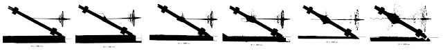
When a shaped charge jet penetrates the sandwich, the interlayer is rapidly displaced by deformation from the passage of the jet. The momentum of the moving interlayer material is transferred into the front and back plates of the sandwich, thus propelling them apart and creating a bulging effect localized around the point penetrated by the jet. The images below show the gradual bulging of the front and back plates due to momentum transfer at four points in time, from 5 microseconds to 20 microseconds. In this case, the impact angle of the jet is normal to the NERA panel so the panel practically does not cause any disruptive effect, but the principle of momentum transfer still occurs nonetheless.

The same process occurs with KE penetrators, but to have a noticeable effect, the NERA panel must be quite thick. Thin panels which are designed to defeat shaped charges generally perform poorly against long rod penetrators.
It is also possible to omit the front plate of a NERA sandwich and have a two-layer panel composed of an inert front plate with a low Young's modulus (typically an elastomer) combined with a steel back plate, or with the two plates in reversed positions. One early configuration of Chobham armour belonged to this class of NERA. Based on a declassified document describing this armour, the thicknesses of the plastic front plate and steel back plate were in a 2:1 ratio.

This type of bulging plate NERA can be effective, with optimized designs such as the one shown in the image below being demonstrated to be capable of reducing the penetration of a shaped charge to less than a half of its original value. However, it is not as effective as an optimized sandwich-type NERA.

The bulging of the front and back plates of the NERA sandwich has the effect of disrupting the shaped charge jet and dispersing it into discrete particles, thus reducing its penetration power when it reaches the main armour plate behind the NERA panel.
Contrary to popular belief, the intersection of the bulging plates with the shaped charge jet does not cause a penetration reduction by forcing the jet to penetrate more material. The total virtual thickness of plate material that intersects with the shaped charge jet is far too little to explain the large reduction in the penetration of the jet. In 2004, Dr. Held published "Dynamic Plate Thickness of ERA Sandwiches against Shaped Charge Jets" in Volume 29 of Propellants, Explosives, Pyrotechnics, issue No. 4. Held examines the mechanism behind the generation of dynamic plate thickness and concludes that the disruption and destruction of shaped charge jets is the main method of jet defeat by reactive armours. In one example given, a 100mm shaped charge which normally achieves a penetration of 800mm has its penetration depth reduced by 560mm after passing through a 3/3/3 reactive armour sandwich. The total dynamic plate thickness in the path of the jet from the two 3mm flyer plates is 270mm (206mm from the rear plate, 63mm from the front plate). Thus, the ERA reduced the penetration depth achieved by the shaped charge by 70%, but the dynamic thickness from the two 3mm flyer plates only accounts for 30% of the reduction.
It is important to note that Held simply defined "dynamic plate thickness" as the virtual plate thickness that intersects with the path of the shaped charge jet. He does not explain how the jet is degraded by the intersection.
Momentum transfer between the bulging plates and the jet causes particles to be displaced from both the plate and the jet. This is responsible for the keyhole-shaped slot cut into bulging plates, and it results in a loss of jet coherence and mass. However, classifying the interaction as the penetration of the moving plate is inaccurate. In actuality, the moving plate is penetrating the shaped charge jet as much as the jet is penetrating the plate, so the mechanism cannot be described as simple armour penetration by erosion. The most important distinction is that the tip of the cumulative jet will almost always be on the other side of the plate before the plate even begins to move due to the immense speed of the jet tip, so it is not the tip of the jet impacting the edges of the plate as the plate moves obliquely against it, but the midsection of the jet body. The interaction causes the jet to be disintegrated, meaning that the single continuous jet is divided into smaller segments, each with their own discrete velocities. The result is that the armour plate behind the NERA plate will be impacted consecutively by two forms of shaped charge jets: a disembodied continuous jet (jet tip), and a smattering of dispersed jet segments. An effective modern ERA design is capable of propelling a flyer plate at such a high velocity that it intercepts the jet tip and destroys it.
The photos below illustrate the effect of a NERA panel on a shaped charge jet. There is no immediate effect 17 microseconds after the jet had perforated the panel, as the jet is still completely intact. 30 microseconds after perforation, the bulging plates have acted on the jet, perturbing it at several points. 45 microseconds after perforation, the bulging action has stopped and the rear of the jet passes through the hole in the NERA panel without being affected.


The body of the jet behind the tip is disturbed due to the formation of instabilities caused by the disruption of the shape of the jet. According to "The role of Kelvin-Helmholz instabilities on shaped charge jet interaction with reactive armour plates", the disruptions experienced by the cumulative jet are Kelvin-Helmholz instabilities. Kelvin-Helmholtz instabilities are formed when there is velocity shear in the continuous flow of a fluid, namely the shaped charge jet.
This is why a shaped charge jet does not penetrate smoothly into armour plate after passing through a NERA plate. Instead, shallow craters are created on a large area of the surface of the plate from the impact of the particulated jet, and some end up on the inside the deepest crater which is invariably made by the disembodied jet tip. Jet particles that do not impact the tunnel made by the disembodied jet tip do not contribute to the final depth of penetration of the target plate. This is best seen in the four photographs below taken from "Study on Rubber Composite Armor Anti‐Shaped Charge Jet Penetration". The craters were produced by a shaped charge jet disturbed by a steel-rubber NERA sandwich panel at four different angles.

The greatest reduction in penetration was achieved when the rubber NERA plate was angled at 60 degrees and the largest amount of jet scattering can also be observed at this angle. It is interesting to note that even at 0 degrees, the NERA plate caused some particulation to occur as evidenced by the shallow pockmarks around the tunnel created by the otherwise untouched shaped charge jet. In this case, the NERA plate acted as simple spaced armour, causing the tip of the jet to lose some material due to the compression of the jet when it passed through the NERA plate and subsequent decompression as it exited. At 30 and 45 degrees, the degree of particulation increased drastically as evident from the much larger surface area covered with pockmarks, but the jet still appears to remain somewhat unperturbed. At 60 degrees, the jet is badly disturbed by the NERA plate and is split into a number of segments. Lateral forces from the bulging plate gives the segments a sideways velocity component, causing them to impact some distance away from the main tunnel created by the disembodied jet tip.
In the paper "A Parametric Study Of The Bulging Process In Passive Cassettes With 2-D Numerical Simulations", Rosenberg states that the motion of bulging plates is not sensitive to obliquity since the main source of propulsion is the energy transferred into the interlayer. In "Study of Jet Interaction with Interlayer Material of Bulging Armor", Yadav states that the amount of energy transferred into the interlayer depends on the duration of contact between the shaped charge jet and the interlayer during penetration, and on the velocity of the jet - the higher the better.
There must be some space behind the NERA plate in order for it to perform efficiently. This is because the perturbations to the shaped charge jet do not manifest until a small period of time has passed. Here are several X-ray photographs, taken from Dr. Manfred Held's paper "Disturbance of Shaped Charge Jets by Bulging Armour", page 194.


The photo below shows three bulging plates shot through by a high power shaped charge jet. Notice that there are keyhole-shaped cuts in the plates, and that the plates are cracked.

More energetic interlayer materials can improve the reaction speed of the NERA plates and increase the lateral energy imparted onto the jet. Rubber is the earliest and most basic material for this application, and can be considered the least sophisticated.
In the study Multiple Cross-Wise Oriented NERA-Panels Against Shaped Charge Warheads, the effectiveness of NERA panels was investigated in various configurations. Experiments were done with a single panel, two panels mounted in parallel, and two panels mounted crosswise. It is most interesting to compare the results obtained with a single panel and two parallel panels.
It is important to note that the experimental setups do not represent practical tank armour because the air gap behind the NERA panels is very large - 590mm in the case of the single panel test and 490mm in the case of the two parallel panels. Overall, the experimental setups had a total "thickness" of 900mm, including the NERA panel, the air gap, and the 180mm base armour. Additionally, it must be noted that for the control test, the shaped charge was detonated at a standoff distance of 450mm from the witness block whereas for the single and double NERA panel experiments, the total standoff distance was 870mm from the witness block. The penetration of the 84mm warhead in the witness block at the control standoff distance of 450mm was 410mm, and it was noted in the study that the optimum standoff for the warhead was 350mm and the penetration at this optimum standoff is 450mm of armour steel. From this, it is clear that the large standoff of 870mm used in the NERA experiments was already capable of reducing the penetration of the SCJ by a significant amount independently from the NERA panels. This is a very common flaw in such studies, and it tends to skew the result in favour of the tested NERA panel design such that immense ME coefficients are obtained, which would otherwise be unobtainable in practice.
Nevertheless, the results are worth studying. It was found that a single NERA panel can decrease the penetration of an 84mm shaped charge warhead from 410mm to just 70mm - a reduction of 83%. Two NERA panels in parallel could reduce the penetration to 60mm - a total reduction of 85%. From this, it can be seen that the second NERA panel is responsible for an additional reduction of only 2%. The very small influence of the second panel is explained by the fact that this type of bulging armour cannot react quickly enough to intercept the tip of a shaped charge jet due to its immense speed. With this type of NERA, it is only possible to cut off the SCJ body trailing behind the tip and reduce its contribution to armour penetration, as shown in the photo below.

The very small reduction in performance offered by the second NERA plate is almost entirely due to the erosion of the SCJ from impacting the material of the panel (two 3mm RHA plates and one 5mm layer of rubber), not by the movement of the plates. This was because the body of the SCJ had been disrupted by the first NERA panel, leaving only the disembodied jet tip to continue. The disturbed jet body could not contribute to the final penetration depth.
Overall, it was demonstrated that NERA panels alone are not enough to stop shaped charges. The SCJ tip is generally too fast to be affected by the movement of the bulging plates, and must be arrested by a back plate or an array of plates of sufficient thickness. It was also demonstrated that there are diminishing returns past a certain number of layers of NERA panels in an armour array as the back layers may not be able to contribute much to the reduction in SCJ penetration. In practical tank armour, it is necessary to sharply reduce the size of the air gap between the NERA panel and the back plate of the armour array due to volume constraints, and to compensate for this, the only option is to increase the number of NERA panels. A large array of NERA panels with a small air gap is generally only capable of a fraction of the performance of a single panel separated from the base armour with a large air gap. The main alternative is to increase the thickness of the back plate of the armour array, but it may not be a viable solution due to weight constraints.
This context is crucial because such details are usually not disclosed outside of esoteric scientific documents, yet it is crucial for determining how effective the armour design will be in practical terms. For example, Polish researcher Pawel Przezdziecki published a wealth of declassified information regarding the development of "Burlington" armour. According to him, the configuration of "Burlington" developed at the turn of the decade from the 1960's to the 1970's had 2-3 times higher mass efficiency than monolithic steel armour against shaped charges and had a similar mass efficiency as monolithic steel armour against KE rounds.
New "Burlington" armour variants from 1978 had a greatly improved mass efficiency of 1.3-1.5 against KE rounds and more than 3.0 against shaped charges. Taking this information at face value, it seems self-evident that the NERA armour found in modern tanks of the early 1980's like the M1 Abrams, Leopard 2 and Challenger 1 would all match or even exceed these parameters, yet, this was not the case.
REFLECTING PLATE ARMOUR

Broadly speaking, this type of NERA is constructed with a thick rigid front plate and a rear bulging plate. It functions with or without an inert interlayer. This type of armour relies on the reflection of shock waves to supply energy for the propulsion of the bulging plate, and as such, it is known as reflecting plate armour.
When a shaped charge jet (SCJ) impacts the plate and begins penetrating it, shock waves propagate from the point of contact between the SCJ and the plate material, which is a plastically deforming region. The shock waves travel to the boundary between the thick plate and the bulging plate where it is mostly reflected while some of its energy is transferred into the bulging plate. This energy pushes the bulging plate away perpendicularly from the thick plate.
After the bulging plate is propelled away from the back surface of the thick plate, an air gap is created between the two plates which means that the back surface of the thick plate no longer has a steel-steel interface, but instead has a steel-air interface. The additional shock waves generated by the penetrating SCJ reflect off the boundary, causing fragmented spall to be ejected from the back surface of the thick plate. The stream of spall fragments travels perpendicular to the thick plate. Like conventional bulging plate NERA, the reflecting plate panel must be set at an oblique angle to the SCJ to ensure that the bulging plate and the spall fragments travel obliquely relative to the SCJ.

As both the bulging plate and the spall fragments travel obliquely relative to the SCJ, their dynamic trajectory intersects with the SCJ. The interaction between these elements is the same as in conventional bulging plate armour, but with a reduced intensity as the energy imparted into the bulging plate by boundary reflection is limited so the momentum of the bulging plate is relatively small, and the spall fragments also have a limited momentum. The intensity of the effect can be enhanced by placing a filler material between the bulging plate from the front plate as shown in the image below. This configuration, which is used in the Object 184 turret, is still considered a form of reflecting plate armour.

When a SCJ or KE penetrator strikes the thick steel front plate, shock waves propagate from the point of contact until it reaches the back surface, whereupon some of the energy is transmitted into the interlayer and some of the energy is converted into kinetic energy by their reflection at the boundary between the back surface and the inert interlayer. This causes the interlayer to be propelled away from the back surface. The energy that is transmitted into the interlayer propagates to the interface between the interlayer and the bulging layer, and the same process repeats, resulting in the bulging plate being propelled away from the interlayer. Through the propagation and reflection of shock waves, the interlayer and back plate are both propelled away from the thick steel front plate before the SCJ or KE penetrator even reaches the interlayer. When the SCJ or long rod penetrator reaches the inert interlayer, additional energy is imparted into it by momentum transfer which further accelerates the bulging effect.

The two factors in the choice of different materials for the interlayer are to change the characteristics of the propagation and reflectance of stress waves between the boundaries, and change the momentum transfer characteristics from the penetrator into the interlayer.
Additionally, it is stated on page 284 in the textbook "Armour: Materials, Theory, and Design" by Paul J. Hazell (professor of Impact Dynamics at UNSW Australia), that it is advantageous for the hole formed by the penetrating jet in the front plate to be as small as possible to maximize the effects of the interaction between the jet and the plate, i.e. material compression and shock wave emanation and propagation. This can be achieved using high-hardness steels for the front plate.
Because the energy of the SCJ is extracted by a combination of shock wave reflection together with momentum transfer instead of momentum transfer alone, a larger amount of energy may be transferred into a reflecting plate armour panel compared to a conventional bulging plate panel. This allows the bulging plate of the reflecting plate armour panel to move at greater velocity, which increases its effectiveness. The reaction time of the reflecting plate armour will be noticeably shorter for the reasons outlined previously. Adding on to those effects, the thick front plate will slow down the jet somewhat before it reaches the interlayer, which creates a larger delay that allows the interlayer and bulging plate to attain a higher velocity before the jet tip eventually reaches it. The drawing below shows the passage of the SCJ through reflecting plate armour in three successive stages.

The first stage shows the SCJ penetrating the front plate and the propagation of shock waves, which causes the interlayer and the bulging plate to move. The second stage shows the breakout of the SCJ from the back surface of the front plate, causing a further expansion of the rubber interlayer and the subsequent bulging of the thin rear plate. The third stage shows the full extent of the bulging effect after the SCJ has perforated the interlayer.
A Chinese analogue of this type of armour was described to have the same operating principles. While the inert interlayer and bulging plate are violently propelled in pursuit of the shaped charge jet, the high hardness steel front plate remains rigidly fixed.

The unidirectional NERA plate might propel its single bulging plate more violently, since all of the energy absorbed into the inert sandwich layer is used to propel only one plate and not two. Still, the effect of a single bulging plate will be less effective than two plates taken together, because there is one fewer plate to disrupt the cumulative jet. However, this might be compensated by emphasizing more violent expansion in a certain direction, as shown below:


(a) "Backwards moving" means that the plate bulges against the direction of travel of the jet. This is known as an "in retreat" or "head-on" type NERA.
(b) "Forwards moving" means that the plate bulges in the same direction as the direction of travel of the jet. This is known as an "in pursuit" type NERA.
The pictures above are not of an actual simulation of SCJ hitting a NERA panel. The plates pictured were moved by explosives which were detonated before the jet reached the plate, but they achieve the same effect in its essence. The photos above shed light on an extremely important phenomenon, which is integral to the operation of the armour of the T-72B. In the turret, the NERA panels are all of the "in pursuit" type. This maximizes their performance, effectively reversing any penalties potentially incurred by the unidirectional design, or at least neutralizing the disadvantages.
The two graphs below show the change in residual penetration depth of a 100mm shaped charge warhead into an armour steel witness block after perforating a NERA panel. The graph on the right is for a single reflecting plate armour panel, and the graph on the left is for conventional NERA panels, with one curve for a single NERA panel and another curve for two parallel NERA panels. For this comparison, the single NERA panel is compared to the single reflecting plate armour panel. In both graphs, the y-axis is the residual penetration in the witness block and the x-axis is the angle of the panels. Note that the angle of the NERA panel given in the left graph is measured from the vertical axis and not the vertical axis. Also, it is worth noting that the standoff distance between the warhead and the conventional NERA panel is 250mm, whereas it is only 150mm on the reflecting plate panel. As such, the comparison is not exact.


("三明治" 结构 - single NERA panel)
(双"三明治" 结构 - two parallel NERA panels)
From a visual comparison of the two graphs, it can be clearly seen that the curve for the single NERA panel and the curve for the reflecting plate panel are identical. As such, it can be concluded that the influence of obliquity is identical for reflecting plate NERA and conventional NERA. In both cases, the difference in penetration power from 45 degrees to 70 degrees is 62%.
For the reflecting plate armour panel experiment, the residual penetration of the 100mm shaped charge is around 400mm (extrapolated from curve) when the panel is set at 45 degrees, and it is 150mm when the panel is set at 70 degrees.
For the conventional NERA panel experiment, the residual penetration of the 100mm shaped charge is around 420mm when the panel is set at 45 degrees (extrapolated from curve), and it is 160mm when the panel is set at 70 degrees (20 degrees from horizontal).
At all angles from 45 degrees to 70 degrees, the residual penetration of the 100mm shaped charge is marginally less after passing through the reflecting plate armour compared to the conventional NERA. The comparison is not perfect because the standoff distances differ, but even so, it is abundantly clear that reflecting plate armour is not necessarily worse than conventional NERA despite having only one bulging plate instead of two, and on the contrary, it can even slightly outperform conventional NERA against shaped charges.
Unfortunately, tests were not done for two parallel reflecting plate panels and such information is extremely difficult to obtain in the public domain, so it is difficult to evaluate the effectiveness of this arrangement compared to conventional NERA. Based on the principal operating mechanisms involved, reflecting plate armour will also suffer from diminishing returns when arranged in an array. However, unlike conventional NERA panels, the thicker plates are capable of affecting the SCJ tip by subjecting it to stronger alternating cycles of stress accumulation and stress release, and also by offering a passive barrier that erodes the SCJ tip. Or in other words, it can perform as more effective spaced armour.
CONVENTIONAL BULGING PLATE NERA


When a shaped charge jet penetrates the sandwich, the interlayer is rapidly displaced by deformation from the passage of the jet. The momentum of the moving interlayer material is transferred into the front and back plates of the sandwich, thus propelling them apart and creating a bulging effect localized around the point penetrated by the jet. The images below show the gradual bulging of the front and back plates due to momentum transfer at four points in time, from 5 microseconds to 20 microseconds. In this case, the impact angle of the jet is normal to the NERA panel so the panel practically does not cause any disruptive effect, but the principle of momentum transfer still occurs nonetheless.

The same process occurs with KE penetrators, but to have a noticeable effect, the NERA panel must be quite thick. Thin panels which are designed to defeat shaped charges generally perform poorly against long rod penetrators.
It is also possible to omit the front plate of a NERA sandwich and have a two-layer panel composed of an inert front plate with a low Young's modulus (typically an elastomer) combined with a steel back plate, or with the two plates in reversed positions. One early configuration of Chobham armour belonged to this class of NERA. Based on a declassified document describing this armour, the thicknesses of the plastic front plate and steel back plate were in a 2:1 ratio.

This type of bulging plate NERA can be effective, with optimized designs such as the one shown in the image below being demonstrated to be capable of reducing the penetration of a shaped charge to less than a half of its original value. However, it is not as effective as an optimized sandwich-type NERA.

The bulging of the front and back plates of the NERA sandwich has the effect of disrupting the shaped charge jet and dispersing it into discrete particles, thus reducing its penetration power when it reaches the main armour plate behind the NERA panel.
Contrary to popular belief, the intersection of the bulging plates with the shaped charge jet does not cause a penetration reduction by forcing the jet to penetrate more material. The total virtual thickness of plate material that intersects with the shaped charge jet is far too little to explain the large reduction in the penetration of the jet. In 2004, Dr. Held published "Dynamic Plate Thickness of ERA Sandwiches against Shaped Charge Jets" in Volume 29 of Propellants, Explosives, Pyrotechnics, issue No. 4. Held examines the mechanism behind the generation of dynamic plate thickness and concludes that the disruption and destruction of shaped charge jets is the main method of jet defeat by reactive armours. In one example given, a 100mm shaped charge which normally achieves a penetration of 800mm has its penetration depth reduced by 560mm after passing through a 3/3/3 reactive armour sandwich. The total dynamic plate thickness in the path of the jet from the two 3mm flyer plates is 270mm (206mm from the rear plate, 63mm from the front plate). Thus, the ERA reduced the penetration depth achieved by the shaped charge by 70%, but the dynamic thickness from the two 3mm flyer plates only accounts for 30% of the reduction.
Momentum transfer between the bulging plates and the jet causes particles to be displaced from both the plate and the jet. This is responsible for the keyhole-shaped slot cut into bulging plates, and it results in a loss of jet coherence and mass. However, classifying the interaction as the penetration of the moving plate is inaccurate. In actuality, the moving plate is penetrating the shaped charge jet as much as the jet is penetrating the plate, so the mechanism cannot be described as simple armour penetration by erosion. The most important distinction is that the tip of the cumulative jet will almost always be on the other side of the plate before the plate even begins to move due to the immense speed of the jet tip, so it is not the tip of the jet impacting the edges of the plate as the plate moves obliquely against it, but the midsection of the jet body. The interaction causes the jet to be disintegrated, meaning that the single continuous jet is divided into smaller segments, each with their own discrete velocities. The result is that the armour plate behind the NERA plate will be impacted consecutively by two forms of shaped charge jets: a disembodied continuous jet (jet tip), and a smattering of dispersed jet segments. An effective modern ERA design is capable of propelling a flyer plate at such a high velocity that it intercepts the jet tip and destroys it.
It is important to note that Held simply defined "dynamic plate thickness" as the virtual plate thickness that intersects with the path of the shaped charge jet. He does not explain how the jet is degraded by the intersection.
The photos below illustrate the effect of a NERA panel on a shaped charge jet. There is no immediate effect 17 microseconds after the jet had perforated the panel, as the jet is still completely intact. 30 microseconds after perforation, the bulging plates have acted on the jet, perturbing it at several points. 45 microseconds after perforation, the bulging action has stopped and the rear of the jet passes through the hole in the NERA panel without being affected.

The body of the jet behind the tip is disturbed due to the formation of instabilities caused by the disruption of the shape of the jet. According to "The role of Kelvin-Helmholz instabilities on shaped charge jet interaction with reactive armour plates", the disruptions experienced by the cumulative jet are Kelvin-Helmholz instabilities. Kelvin-Helmholtz instabilities are formed when there is velocity shear in the continuous flow of a fluid, namely the shaped charge jet.
This is why a shaped charge jet does not penetrate smoothly into armour plate after passing through a NERA plate. Instead, shallow craters are created on a large area of the surface of the plate from the impact of the particulated jet, and some end up on the inside the deepest crater which is invariably made by the disembodied jet tip. Jet particles that do not impact the tunnel made by the disembodied jet tip do not contribute to the final depth of penetration of the target plate. This is best seen in the four photographs below taken from "Study on Rubber Composite Armor Anti‐Shaped Charge Jet Penetration". The craters were produced by a shaped charge jet disturbed by a steel-rubber NERA sandwich panel at four different angles.

The greatest reduction in penetration was achieved when the rubber NERA plate was angled at 60 degrees and the largest amount of jet scattering can also be observed at this angle. It is interesting to note that even at 0 degrees, the NERA plate caused some particulation to occur as evidenced by the shallow pockmarks around the tunnel created by the otherwise untouched shaped charge jet. In this case, the NERA plate acted as simple spaced armour, causing the tip of the jet to lose some material due to the compression of the jet when it passed through the NERA plate and subsequent decompression as it exited. At 30 and 45 degrees, the degree of particulation increased drastically as evident from the much larger surface area covered with pockmarks, but the jet still appears to remain somewhat unperturbed. At 60 degrees, the jet is badly disturbed by the NERA plate and is split into a number of segments. Lateral forces from the bulging plate gives the segments a sideways velocity component, causing them to impact some distance away from the main tunnel created by the disembodied jet tip.
In the paper "A Parametric Study Of The Bulging Process In Passive Cassettes With 2-D Numerical Simulations", Rosenberg states that the motion of bulging plates is not sensitive to obliquity since the main source of propulsion is the energy transferred into the interlayer. In "Study of Jet Interaction with Interlayer Material of Bulging Armor", Yadav states that the amount of energy transferred into the interlayer depends on the duration of contact between the shaped charge jet and the interlayer during penetration, and on the velocity of the jet - the higher the better.
In the paper "A Parametric Study Of The Bulging Process In Passive Cassettes With 2-D Numerical Simulations", Rosenberg states that the motion of bulging plates is not sensitive to obliquity since the main source of propulsion is the energy transferred into the interlayer. In "Study of Jet Interaction with Interlayer Material of Bulging Armor", Yadav states that the amount of energy transferred into the interlayer depends on the duration of contact between the shaped charge jet and the interlayer during penetration, and on the velocity of the jet - the higher the better.
There must be some space behind the NERA plate in order for it to perform efficiently. This is because the perturbations to the shaped charge jet do not manifest until a small period of time has passed. Here are several X-ray photographs, taken from Dr. Manfred Held's paper "Disturbance of Shaped Charge Jets by Bulging Armour", page 194.


The photo below shows three bulging plates shot through by a high power shaped charge jet. Notice that there are keyhole-shaped cuts in the plates, and that the plates are cracked.

More energetic interlayer materials can improve the reaction speed of the NERA plates and increase the lateral energy imparted onto the jet. Rubber is the earliest and most basic material for this application, and can be considered the least sophisticated.
In the study Multiple Cross-Wise Oriented NERA-Panels Against Shaped Charge Warheads, the effectiveness of NERA panels was investigated in various configurations. Experiments were done with a single panel, two panels mounted in parallel, and two panels mounted crosswise. It is most interesting to compare the results obtained with a single panel and two parallel panels.
It is important to note that the experimental setups do not represent practical tank armour because the air gap behind the NERA panels is very large - 590mm in the case of the single panel test and 490mm in the case of the two parallel panels. Overall, the experimental setups had a total "thickness" of 900mm, including the NERA panel, the air gap, and the 180mm base armour. Additionally, it must be noted that for the control test, the shaped charge was detonated at a standoff distance of 450mm from the witness block whereas for the single and double NERA panel experiments, the total standoff distance was 870mm from the witness block. The penetration of the 84mm warhead in the witness block at the control standoff distance of 450mm was 410mm, and it was noted in the study that the optimum standoff for the warhead was 350mm and the penetration at this optimum standoff is 450mm of armour steel. From this, it is clear that the large standoff of 870mm used in the NERA experiments was already capable of reducing the penetration of the SCJ by a significant amount independently from the NERA panels. This is a very common flaw in such studies, and it tends to skew the result in favour of the tested NERA panel design such that immense ME coefficients are obtained, which would otherwise be unobtainable in practice.
Nevertheless, the results are worth studying. It was found that a single NERA panel can decrease the penetration of an 84mm shaped charge warhead from 410mm to just 70mm - a reduction of 83%. Two NERA panels in parallel could reduce the penetration to 60mm - a total reduction of 85%. From this, it can be seen that the second NERA panel is responsible for an additional reduction of only 2%. The very small influence of the second panel is explained by the fact that this type of bulging armour cannot react quickly enough to intercept the tip of a shaped charge jet due to its immense speed. With this type of NERA, it is only possible to cut off the SCJ body trailing behind the tip and reduce its contribution to armour penetration, as shown in the photo below.

The very small reduction in performance offered by the second NERA plate is almost entirely due to the erosion of the SCJ from impacting the material of the panel (two 3mm RHA plates and one 5mm layer of rubber), not by the movement of the plates. This was because the body of the SCJ had been disrupted by the first NERA panel, leaving only the disembodied jet tip to continue. The disturbed jet body could not contribute to the final penetration depth.
Overall, it was demonstrated that NERA panels alone are not enough to stop shaped charges. The SCJ tip is generally too fast to be affected by the movement of the bulging plates, and must be arrested by a back plate or an array of plates of sufficient thickness. It was also demonstrated that there are diminishing returns past a certain number of layers of NERA panels in an armour array as the back layers may not be able to contribute much to the reduction in SCJ penetration. In practical tank armour, it is necessary to sharply reduce the size of the air gap between the NERA panel and the back plate of the armour array due to volume constraints, and to compensate for this, the only option is to increase the number of NERA panels. A large array of NERA panels with a small air gap is generally only capable of a fraction of the performance of a single panel separated from the base armour with a large air gap. The main alternative is to increase the thickness of the back plate of the armour array, but it may not be a viable solution due to weight constraints.
Overall, it was demonstrated that NERA panels alone are not enough to stop shaped charges. The SCJ tip is generally too fast to be affected by the movement of the bulging plates, and must be arrested by a back plate or an array of plates of sufficient thickness. It was also demonstrated that there are diminishing returns past a certain number of layers of NERA panels in an armour array as the back layers may not be able to contribute much to the reduction in SCJ penetration. In practical tank armour, it is necessary to sharply reduce the size of the air gap between the NERA panel and the back plate of the armour array due to volume constraints, and to compensate for this, the only option is to increase the number of NERA panels. A large array of NERA panels with a small air gap is generally only capable of a fraction of the performance of a single panel separated from the base armour with a large air gap. The main alternative is to increase the thickness of the back plate of the armour array, but it may not be a viable solution due to weight constraints.
This context is crucial because such details are usually not disclosed outside of esoteric scientific documents, yet it is crucial for determining how effective the armour design will be in practical terms. For example, Polish researcher Pawel Przezdziecki published a wealth of declassified information regarding the development of "Burlington" armour. According to him, the configuration of "Burlington" developed at the turn of the decade from the 1960's to the 1970's had 2-3 times higher mass efficiency than monolithic steel armour against shaped charges and had a similar mass efficiency as monolithic steel armour against KE rounds.
New "Burlington" armour variants from 1978 had a greatly improved mass efficiency of 1.3-1.5 against KE rounds and more than 3.0 against shaped charges. Taking this information at face value, it seems self-evident that the NERA armour found in modern tanks of the early 1980's like the M1 Abrams, Leopard 2 and Challenger 1 would all match or even exceed these parameters, yet, this was not the case.
REFLECTING PLATE ARMOUR

Broadly speaking, this type of NERA is constructed with a thick rigid front plate and a rear bulging plate. It functions with or without an inert interlayer. This type of armour relies on the reflection of shock waves to supply energy for the propulsion of the bulging plate, and as such, it is known as reflecting plate armour.
After the bulging plate is propelled away from the back surface of the thick plate, an air gap is created between the two plates which means that the back surface of the thick plate no longer has a steel-steel interface, but instead has a steel-air interface. The additional shock waves generated by the penetrating SCJ reflect off the boundary, causing fragmented spall to be ejected from the back surface of the thick plate. The stream of spall fragments travels perpendicular to the thick plate. Like conventional bulging plate NERA, the reflecting plate panel must be set at an oblique angle to the SCJ to ensure that the bulging plate and the spall fragments travel obliquely relative to the SCJ.

As both the bulging plate and the spall fragments travel obliquely relative to the SCJ, their dynamic trajectory intersects with the SCJ. The interaction between these elements is the same as in conventional bulging plate armour, but with a reduced intensity as the energy imparted into the bulging plate by boundary reflection is limited so the momentum of the bulging plate is relatively small, and the spall fragments also have a limited momentum. The intensity of the effect can be enhanced by placing a filler material between the bulging plate from the front plate as shown in the image below. This configuration, which is used in the Object 184 turret, is still considered a form of reflecting plate armour.

When a SCJ or KE penetrator strikes the thick steel front plate, shock waves propagate from the point of contact until it reaches the back surface, whereupon some of the energy is transmitted into the interlayer and some of the energy is converted into kinetic energy by their reflection at the boundary between the back surface and the inert interlayer. This causes the interlayer to be propelled away from the back surface. The energy that is transmitted into the interlayer propagates to the interface between the interlayer and the bulging layer, and the same process repeats, resulting in the bulging plate being propelled away from the interlayer. Through the propagation and reflection of shock waves, the interlayer and back plate are both propelled away from the thick steel front plate before the SCJ or KE penetrator even reaches the interlayer. When the SCJ or long rod penetrator reaches the inert interlayer, additional energy is imparted into it by momentum transfer which further accelerates the bulging effect.

Additionally, it is stated on page 284 in the textbook "Armour: Materials, Theory, and Design" by Paul J. Hazell (professor of Impact Dynamics at UNSW Australia), that it is advantageous for the hole formed by the penetrating jet in the front plate to be as small as possible to maximize the effects of the interaction between the jet and the plate, i.e. material compression and shock wave emanation and propagation. This can be achieved using high-hardness steels for the front plate.
Because the energy of the SCJ is extracted by a combination of shock wave reflection together with momentum transfer instead of momentum transfer alone, a larger amount of energy may be transferred into a reflecting plate armour panel compared to a conventional bulging plate panel. This allows the bulging plate of the reflecting plate armour panel to move at greater velocity, which increases its effectiveness. The reaction time of the reflecting plate armour will be noticeably shorter for the reasons outlined previously. Adding on to those effects, the thick front plate will slow down the jet somewhat before it reaches the interlayer, which creates a larger delay that allows the interlayer and bulging plate to attain a higher velocity before the jet tip eventually reaches it. The drawing below shows the passage of the SCJ through reflecting plate armour in three successive stages.
The first stage shows the SCJ penetrating the front plate and the propagation of shock waves, which causes the interlayer and the bulging plate to move. The second stage shows the breakout of the SCJ from the back surface of the front plate, causing a further expansion of the rubber interlayer and the subsequent bulging of the thin rear plate. The third stage shows the full extent of the bulging effect after the SCJ has perforated the interlayer.
A Chinese analogue of this type of armour was described to have the same operating principles. While the inert interlayer and bulging plate are violently propelled in pursuit of the shaped charge jet, the high hardness steel front plate remains rigidly fixed.

The unidirectional NERA plate might propel its single bulging plate more violently, since all of the energy absorbed into the inert sandwich layer is used to propel only one plate and not two. Still, the effect of a single bulging plate will be less effective than two plates taken together, because there is one fewer plate to disrupt the cumulative jet. However, this might be compensated by emphasizing more violent expansion in a certain direction, as shown below:
(a) "Backwards moving" means that the plate bulges against the direction of travel of the jet. This is known as an "in retreat" or "head-on" type NERA.
(b) "Forwards moving" means that the plate bulges in the same direction as the direction of travel of the jet. This is known as an "in pursuit" type NERA.
The pictures above are not of an actual simulation of SCJ hitting a NERA panel. The plates pictured were moved by explosives which were detonated before the jet reached the plate, but they achieve the same effect in its essence. The photos above shed light on an extremely important phenomenon, which is integral to the operation of the armour of the T-72B. In the turret, the NERA panels are all of the "in pursuit" type. This maximizes their performance, effectively reversing any penalties potentially incurred by the unidirectional design, or at least neutralizing the disadvantages.
The two graphs below show the change in residual penetration depth of a 100mm shaped charge warhead into an armour steel witness block after perforating a NERA panel. The graph on the right is for a single reflecting plate armour panel, and the graph on the left is for conventional NERA panels, with one curve for a single NERA panel and another curve for two parallel NERA panels. For this comparison, the single NERA panel is compared to the single reflecting plate armour panel. In both graphs, the y-axis is the residual penetration in the witness block and the x-axis is the angle of the panels. Note that the angle of the NERA panel given in the left graph is measured from the vertical axis and not the vertical axis. Also, it is worth noting that the standoff distance between the warhead and the conventional NERA panel is 250mm, whereas it is only 150mm on the reflecting plate panel. As such, the comparison is not exact.


("三明治" 结构 - single NERA panel)
(双"三明治" 结构 - two parallel NERA panels)
From a visual comparison of the two graphs, it can be clearly seen that the curve for the single NERA panel and the curve for the reflecting plate panel are identical. As such, it can be concluded that the influence of obliquity is identical for reflecting plate NERA and conventional NERA. In both cases, the difference in penetration power from 45 degrees to 70 degrees is 62%.
For the reflecting plate armour panel experiment, the residual penetration of the 100mm shaped charge is around 400mm (extrapolated from curve) when the panel is set at 45 degrees, and it is 150mm when the panel is set at 70 degrees.
For the conventional NERA panel experiment, the residual penetration of the 100mm shaped charge is around 420mm when the panel is set at 45 degrees (extrapolated from curve), and it is 160mm when the panel is set at 70 degrees (20 degrees from horizontal).
At all angles from 45 degrees to 70 degrees, the residual penetration of the 100mm shaped charge is marginally less after passing through the reflecting plate armour compared to the conventional NERA. The comparison is not perfect because the standoff distances differ, but even so, it is abundantly clear that reflecting plate armour is not necessarily worse than conventional NERA despite having only one bulging plate instead of two, and on the contrary, it can even slightly outperform conventional NERA against shaped charges.
Unfortunately, tests were not done for two parallel reflecting plate panels and such information is extremely difficult to obtain in the public domain, so it is difficult to evaluate the effectiveness of this arrangement compared to conventional NERA. Based on the principal operating mechanisms involved, reflecting plate armour will also suffer from diminishing returns when arranged in an array. However, unlike conventional NERA panels, the thicker plates are capable of affecting the SCJ tip by subjecting it to stronger alternating cycles of stress accumulation and stress release, and also by offering a passive barrier that erodes the SCJ tip. Or in other words, it can perform as more effective spaced armour.
EFFECT ON HEAT THREATS
The X-ray photograph below (from NII Stali) shows a sample of the NERA plates used in the Object 184 turret being tested. The plate in the photo is angled at 68 degrees.

The bulging plate is very strongly deflected, and it can be seen that large disrupted portions in the jet, like troughs in a sine graph, appear quite often down the length of the jet, indicating the the jet is highly disrupted. It is unfortunate that the photo is so closely focused on the NERA panel, as the tip of the jet is out of frame so its length and condition cannot be observed. It is quite clear that the disturbances in the jet only appear after travelling a certain distance behind the bulging plate, which is completely consistent with Dr. Held's findings in "Disturbance of Shaped Charge Jets by Bulging Armour".
Based on the available information, the specific design of the reflecting plate panels in an Object 184 turret cavity appears to have been optimized to defeat shaped charge warheads within a fairly broad range of common calibers. In page 286 of the textbook "Particular Questions of Terminal Ballistics" 2006 (Частные Вопросы Конечной Баллистики) published by Bauman Moscow State Technical University on behalf of NII Stali, an optimal distribution of thicknesses of the five basic elements of a NERA sandwich with a rubber interlayer was formulated based on data accumulated from testing and simulating armour of this type. The study posits that the most rational distribution of thicknesses is as follows:
- Steel front plate - thicknesses equal to 0.2-0.5 times the caliber of the HEAT warhead.
- Rubber interlayer - thickness equal to 1.0-2.0 times the diameter of the shaped charge jet.
- Thin steel bulging plate - thickness equal to 1.5 times the diameter of the shaped charge jet.
- Size of the air gap behind the thin steel bulging plate - 0.4 times the caliber of the HEAT warhead.
- The optimal angle of the NERA panel - 60 to 70 degrees.
Note that the jet diameter of a typical anti-tank shaped charge warhead is 2.5-3.5mm. Based on this, it appears that the NERA panels in the armour of the T-72B were designed with realistic threats in mind, having a reasonable ratio of thicknesses in each panel and appropriately sized air gaps between each panel. Moreover, the use of BTK-1Sh for the front plate of the reflecting plate armour optimizes its performance against SCJs, as the use of high hardness steel for the front plate is advantageous according to professor Paul Hazell.
However, there is a major downside to the armour layout. The main issue is that the panels are not placed at the optimum angle - the structural obliquity of the reflecting plate NERA panels from the direct front is just 35 degrees; very far from the ideal range of 60-70 degrees. That said, the number of panels in the path of the penetrator is very large if the turret is hit from the direct front. Also, the turret is not only required to withstand attacks from the direct front, but also from a side angle of up to 30 degrees. Due to the structural obliquity of the NERA panels, aiming at the turret from a side angle of 30 degrees generates a relative obliquity of 65 degrees.
A more tangible shortcoming of the armour array design is that there is no air gap separating the NERA array from the back plate of the turret armour, and hence, an SCJ may only break up while it travels through the NERA array. This is chiefly due to volumetric constraints. Given a fixed volume for the armour, the only way to introduce an air gap in this location is to remove armour material, which inevitably leads to a net loss in effective thickness even if the mass efficiency of the armour array may rise.
Aside from the reflecting plate armour itself, some other traits of the turret armour array are worth noting. The thick steel armour in front of the turret cheek cavities slows down an SCJ before it enters the reflecting plate armour array, and thus improve their performance due to the longer interaction time between the bulging plate and the jet tip. This was shown in the study "Shaped Charge Optimisation against Bulging Targets" authored by Dr. Held, where it was found that as the velocity of a shaped charge jet tip decreases, the effectiveness of bulging armour increases.
The velocity of the shaped charge jets was adjusted by varying the thickness of the shaped charge liner without changing the the diameter or the cone angle, which remain at 96mm and 60° respectively. The target was a 10mm steel plate in front of a 2/15/4 bulging armour plate. Shaped charges with liner thicknesses of 1mm, 2mm, 3mm and 4mm were tested. As the thickness of the shape charge liner increases, the jet tip velocity decreases. Jet tip dimeter, however, was unaffected. All warheads were detonated at a standoff of 2 CDs, except for the 2mm liner warhead, which was detonated at 6 CD. This skewed the results slightly, but the shaped charges consistently exhibited more symptoms of disturbance as the liner thickness increases.
According to the textbook "Частные Вопросы Конечной Баллистики", the increase in mass efficiency for shaped charge protection achieved by multi-layered armour using reflecting plate panels is up to 40% compared to homogeneous steel armour of medium hardness, and the armour is more effective than a spaced steel armour array of the same weight by 10-23%. From these figures, it can be said that the mass efficiency of the armour of the T-72B (depending on the angle of attack) can be as high as 40%, depending on the side angle. Based on the claim that this type of NERA armour is 10-23% more effective than spaced steel armour of the same weight, it can be surmised that spaced steel armour would have a mass efficiency of 1.14 to 1.27 compared to homogeneous steel armour whereas the same armour array with NERA has a mass efficiency of 1.4, so even if NERA were absent, the spaced steel plates alone provide more protection than their weight suggests.
The relatively low ME coefficient is realistic given that it represents a setup where the reflecting plate panels are part of a multi-layered armour array for a tank. The constraints for actual tank armour include limited internal volume which limits the size of the air gaps and the permissible mounting angle of the internal NERA panels. Due to these real world constraints, much of the efficiency is lost after averaging out the numbers from including thick steel plates into the array. Therefore, a direct comparison between NERA designs examined in various scientific studies and the NERA armour of the T-72B is not valid.
The X-ray photograph below (from NII Stali) shows a sample of the NERA plates used in the Object 184 turret being tested. The plate in the photo is angled at 68 degrees.

The bulging plate is very strongly deflected, and it can be seen that large disrupted portions in the jet, like troughs in a sine graph, appear quite often down the length of the jet, indicating the the jet is highly disrupted. It is unfortunate that the photo is so closely focused on the NERA panel, as the tip of the jet is out of frame so its length and condition cannot be observed. It is quite clear that the disturbances in the jet only appear after travelling a certain distance behind the bulging plate, which is completely consistent with Dr. Held's findings in "Disturbance of Shaped Charge Jets by Bulging Armour".
Based on the available information, the specific design of the reflecting plate panels in an Object 184 turret cavity appears to have been optimized to defeat shaped charge warheads within a fairly broad range of common calibers. In page 286 of the textbook "Particular Questions of Terminal Ballistics" 2006 (Частные Вопросы Конечной Баллистики) published by Bauman Moscow State Technical University on behalf of NII Stali, an optimal distribution of thicknesses of the five basic elements of a NERA sandwich with a rubber interlayer was formulated based on data accumulated from testing and simulating armour of this type. The study posits that the most rational distribution of thicknesses is as follows:
- Steel front plate - thicknesses equal to 0.2-0.5 times the caliber of the HEAT warhead.
- Rubber interlayer - thickness equal to 1.0-2.0 times the diameter of the shaped charge jet.
- Thin steel bulging plate - thickness equal to 1.5 times the diameter of the shaped charge jet.
- Size of the air gap behind the thin steel bulging plate - 0.4 times the caliber of the HEAT warhead.
- The optimal angle of the NERA panel - 60 to 70 degrees.
Note that the jet diameter of a typical anti-tank shaped charge warhead is 2.5-3.5mm. Based on this, it appears that the NERA panels in the armour of the T-72B were designed with realistic threats in mind, having a reasonable ratio of thicknesses in each panel and appropriately sized air gaps between each panel. Moreover, the use of BTK-1Sh for the front plate of the reflecting plate armour optimizes its performance against SCJs, as the use of high hardness steel for the front plate is advantageous according to professor Paul Hazell.
However, there is a major downside to the armour layout. The main issue is that the panels are not placed at the optimum angle - the structural obliquity of the reflecting plate NERA panels from the direct front is just 35 degrees; very far from the ideal range of 60-70 degrees. That said, the number of panels in the path of the penetrator is very large if the turret is hit from the direct front. Also, the turret is not only required to withstand attacks from the direct front, but also from a side angle of up to 30 degrees. Due to the structural obliquity of the NERA panels, aiming at the turret from a side angle of 30 degrees generates a relative obliquity of 65 degrees.
A more tangible shortcoming of the armour array design is that there is no air gap separating the NERA array from the back plate of the turret armour, and hence, an SCJ may only break up while it travels through the NERA array. This is chiefly due to volumetric constraints. Given a fixed volume for the armour, the only way to introduce an air gap in this location is to remove armour material, which inevitably leads to a net loss in effective thickness even if the mass efficiency of the armour array may rise.
Aside from the reflecting plate armour itself, some other traits of the turret armour array are worth noting. The thick steel armour in front of the turret cheek cavities slows down an SCJ before it enters the reflecting plate armour array, and thus improve their performance due to the longer interaction time between the bulging plate and the jet tip. This was shown in the study "Shaped Charge Optimisation against Bulging Targets" authored by Dr. Held, where it was found that as the velocity of a shaped charge jet tip decreases, the effectiveness of bulging armour increases.
The velocity of the shaped charge jets was adjusted by varying the thickness of the shaped charge liner without changing the the diameter or the cone angle, which remain at 96mm and 60° respectively. The target was a 10mm steel plate in front of a 2/15/4 bulging armour plate. Shaped charges with liner thicknesses of 1mm, 2mm, 3mm and 4mm were tested. As the thickness of the shape charge liner increases, the jet tip velocity decreases. Jet tip dimeter, however, was unaffected. All warheads were detonated at a standoff of 2 CDs, except for the 2mm liner warhead, which was detonated at 6 CD. This skewed the results slightly, but the shaped charges consistently exhibited more symptoms of disturbance as the liner thickness increases.
According to the textbook "Частные Вопросы Конечной Баллистики", the increase in mass efficiency for shaped charge protection achieved by multi-layered armour using reflecting plate panels is up to 40% compared to homogeneous steel armour of medium hardness, and the armour is more effective than a spaced steel armour array of the same weight by 10-23%. From these figures, it can be said that the mass efficiency of the armour of the T-72B (depending on the angle of attack) can be as high as 40%, depending on the side angle. Based on the claim that this type of NERA armour is 10-23% more effective than spaced steel armour of the same weight, it can be surmised that spaced steel armour would have a mass efficiency of 1.14 to 1.27 compared to homogeneous steel armour whereas the same armour array with NERA has a mass efficiency of 1.4, so even if NERA were absent, the spaced steel plates alone provide more protection than their weight suggests.
The relatively low ME coefficient is realistic given that it represents a setup where the reflecting plate panels are part of a multi-layered armour array for a tank. The constraints for actual tank armour include limited internal volume which limits the size of the air gaps and the permissible mounting angle of the internal NERA panels. Due to these real world constraints, much of the efficiency is lost after averaging out the numbers from including thick steel plates into the array. Therefore, a direct comparison between NERA designs examined in various scientific studies and the NERA armour of the T-72B is not valid.
HEAT PROTECTION
On page 138 of the book "T-72/T-90: Опыт создания отечественных основных боевых танков" it is stated that according to calculated data from 1982, the frontal arc armour provided protection from shaped charges with a penetration of up to 600-620mm RHA. The effective thickness of the armour may therefore be 630-650mm RHA.
Based on the earlier discussion on the design and operation of NERA, the mass efficiency coefficient of Russian "multi-layered armour" incorporating NERA against HEAT should be 1.4. Treating the turret armour of the T-72B as such, we can multiply the mass of the armour from a front view (648mm) by 1.4 to obtain 907mm. However, it is unlikely that the full value of the coefficient can be reached because the NERA panels are only set at a relative obliquity of 35 degrees when the turret is impacted from the direct front.
At a 30-degree side angle, the weight of the armour is greatly reduced and the effective thickness must be lower as a result. However, the NERA panels in the armour cavity reach a relative obliquity of 65 degrees at this angle of attack, so the full mass efficiency coefficient of 1.4 should be applied. The armour should reach an effective thickness of 647mm RHA against shaped charge warheads. Overall, these estimates are in good agreement with the claimed protection value given in the book "T-72/T-90: Опыт создания отечественных основных боевых танков".
In the NII Stali website guestbook (forum) from 2012-2013, a NII Stali website administrator claimed that a T-72B turret can resist a "Konkurs" ATGM without Kontakt-1. The 9N131 warhead used in the basic 9M113 missile (1974) penetrates 550mm RHA, and the enhanced 9N131M warhead used in the upgraded 9M113 (mid-1980's) penetrates 630mm RHA. Based on the available information, the turret may confidently withstand the former type from a 60-degree frontal arc and it may still resist the latter type, albeit by a small margin. In general, the available information is quite consistent.
This level of protection is sufficient for common anti-tank missiles and most shoulder-fired anti-tank grenades. It is the same level of protection achieved by the M1 Abrams and Leopard 2, which were tested against a very similar threat. During their development, the XM1 was tested against the 5" BRL precision shaped charge with 636mm of penetration, and the Leopard 2AV was tested against the same 5" BRL precision shaped charge but with 600mm of penetration. The reduced penetration power was achieved by adjusting the stand off distance. The armour of both tanks could resist the threat and were not tested against more powerful warheads. As such, the effective thickness of both the M1 Abrams and Leopard 2 can be considered to reach approximately 650mm RHA at a 30-degree side angle.
However, even though the effective thickness of the Object 184 turret is good, the main issue is that the contemporary ATGM systems of the mid 1980's could already overcome it. The main threats were the MILAN 2, TOW-2, HOT, and Hellfire missiles. To withstand these weapons, the armour must be supplemented by Kontakt-1 ERA.
Even shoulder-fired weapons would eventually become a formidable threat. The Panzerfaust 3 (PzF 3) is a good example of this. It began low rate production for evaluation purposes in 1985 and entered mass production at the end of the decade. Weighing in at 2.3 kg, the 110mm caliber warhead of the DM12 round is claimed to be capable of penetrating 700mm RHA in the official website of the Bundeswehr and it is documented in a JPRS (Joint Publications Research Service) report from December 1987 (pages 17, 19) that Dynamit Nobel representatives credited the PzF 3 with "penetrating armor more than 700mm thick". The improved DM12A1 grenade is claimed to be capable of penetrating "steel armor of approximately 800mm thickness" by Dynamit Nobel Defence in a brochure published in August 2010 (page 13). The DM12 round was the only available ammunition type at the turn of the decade, and the DM12A1 became available in the early 1990's, after the conclusion of the Cold War.
The turret of the T-72B should be able to resist this grenade from the direct front, but struggle to do so from a side angle of 30 degrees. From these examples, it is clear that Kontakt-1 is not merely a supplement for the considerable armour of the T-72B but a necessity given the gravity of the threat posed by contemporary NATO weapons.
After the dissolution of the USSR in 1991, a variety of ex-Soviet hardware found its way into foreign hands. A large number of T-72B tanks were shipped over to the U.S and extensively examined along with other T-72 models as well as samples of Kontakt-5 reactive armour, and T-80U tanks equipped with Kontakt-5 were thoroughly examined in Sweden. As a result of this unprecedented insight into Soviet tank armour, the DM22 round for the Panzerfaust 3-T (Tandem) was developed in 1998 to defeat a "T-72 with ERA" (Kontakt-1) and the DM72 round for the Panzerfaust 3-IT (Improved Tandem) was developed in the same year to defeat the T-80U with ERA (Kontakt-5).
The DM22 warhead features 800mm of penetration behind ERA and the DM72 warhead features 900mm of penetration behind ERA. Of course, it is immediately obvious that this shows the existence of a gap between the protection level of the T-80U and the "T-72", and also that it implies a certain level of protection for the two tanks. Based on our knowledge of the level of protection offered by the various T-72 models in existence, the "T-72" must be a T-72B by default as no other model has enough armour to require such a powerful warhead.
EFFECT ON APFSDS
In general, the turret armour can simply be described as a complex spaced armour array, as the bulging plates of the reflecting plate panels will not have a significant effect on a long rod penetrator due to their low thickness and the relatively low bulging velocity. It is the same with conventional NERA panels, but unlike those, the thick, high hardness steel front plates of the reflecting plate panels behave as spaced plates.
The high thickness of steel in front of the reflecting plate armour array can also be advantageous for defeating KE threats. According to German expert Rolf Hilmes, one method to augment the efficacy of NERA against KE threats is to incorporate a heavy armour plate in front of the NERA array, so that the penetrator is shattered or fractured before it enters the array. This may be the function of the heavy cast steel front plate of the turret cheeks. In later iterations of the T-72B, this effect is augmented by Kontakt-5 reactive armour, so that the NERA array in the turret is further amplified.
On page 138 of the book "T-72/T-90: Опыт создания отечественных основных боевых танков" it is stated that according to calculated data from 1982, the frontal arc armour provided protection from shaped charges with a penetration of up to 600-620mm RHA. The effective thickness of the armour may therefore be 630-650mm RHA.
Based on the earlier discussion on the design and operation of NERA, the mass efficiency coefficient of Russian "multi-layered armour" incorporating NERA against HEAT should be 1.4. Treating the turret armour of the T-72B as such, we can multiply the mass of the armour from a front view (648mm) by 1.4 to obtain 907mm. However, it is unlikely that the full value of the coefficient can be reached because the NERA panels are only set at a relative obliquity of 35 degrees when the turret is impacted from the direct front.
At a 30-degree side angle, the weight of the armour is greatly reduced and the effective thickness must be lower as a result. However, the NERA panels in the armour cavity reach a relative obliquity of 65 degrees at this angle of attack, so the full mass efficiency coefficient of 1.4 should be applied. The armour should reach an effective thickness of 647mm RHA against shaped charge warheads. Overall, these estimates are in good agreement with the claimed protection value given in the book "T-72/T-90: Опыт создания отечественных основных боевых танков".
In the NII Stali website guestbook (forum) from 2012-2013, a NII Stali website administrator claimed that a T-72B turret can resist a "Konkurs" ATGM without Kontakt-1. The 9N131 warhead used in the basic 9M113 missile (1974) penetrates 550mm RHA, and the enhanced 9N131M warhead used in the upgraded 9M113 (mid-1980's) penetrates 630mm RHA. Based on the available information, the turret may confidently withstand the former type from a 60-degree frontal arc and it may still resist the latter type, albeit by a small margin. In general, the available information is quite consistent.
This level of protection is sufficient for common anti-tank missiles and most shoulder-fired anti-tank grenades. It is the same level of protection achieved by the M1 Abrams and Leopard 2, which were tested against a very similar threat. During their development, the XM1 was tested against the 5" BRL precision shaped charge with 636mm of penetration, and the Leopard 2AV was tested against the same 5" BRL precision shaped charge but with 600mm of penetration. The reduced penetration power was achieved by adjusting the stand off distance. The armour of both tanks could resist the threat and were not tested against more powerful warheads. As such, the effective thickness of both the M1 Abrams and Leopard 2 can be considered to reach approximately 650mm RHA at a 30-degree side angle.
However, even though the effective thickness of the Object 184 turret is good, the main issue is that the contemporary ATGM systems of the mid 1980's could already overcome it. The main threats were the MILAN 2, TOW-2, HOT, and Hellfire missiles. To withstand these weapons, the armour must be supplemented by Kontakt-1 ERA.
Even shoulder-fired weapons would eventually become a formidable threat. The Panzerfaust 3 (PzF 3) is a good example of this. It began low rate production for evaluation purposes in 1985 and entered mass production at the end of the decade. Weighing in at 2.3 kg, the 110mm caliber warhead of the DM12 round is claimed to be capable of penetrating 700mm RHA in the official website of the Bundeswehr and it is documented in a JPRS (Joint Publications Research Service) report from December 1987 (pages 17, 19) that Dynamit Nobel representatives credited the PzF 3 with "penetrating armor more than 700mm thick". The improved DM12A1 grenade is claimed to be capable of penetrating "steel armor of approximately 800mm thickness" by Dynamit Nobel Defence in a brochure published in August 2010 (page 13). The DM12 round was the only available ammunition type at the turn of the decade, and the DM12A1 became available in the early 1990's, after the conclusion of the Cold War.
The turret of the T-72B should be able to resist this grenade from the direct front, but struggle to do so from a side angle of 30 degrees. From these examples, it is clear that Kontakt-1 is not merely a supplement for the considerable armour of the T-72B but a necessity given the gravity of the threat posed by contemporary NATO weapons.
After the dissolution of the USSR in 1991, a variety of ex-Soviet hardware found its way into foreign hands. A large number of T-72B tanks were shipped over to the U.S and extensively examined along with other T-72 models as well as samples of Kontakt-5 reactive armour, and T-80U tanks equipped with Kontakt-5 were thoroughly examined in Sweden. As a result of this unprecedented insight into Soviet tank armour, the DM22 round for the Panzerfaust 3-T (Tandem) was developed in 1998 to defeat a "T-72 with ERA" (Kontakt-1) and the DM72 round for the Panzerfaust 3-IT (Improved Tandem) was developed in the same year to defeat the T-80U with ERA (Kontakt-5).
The DM22 warhead features 800mm of penetration behind ERA and the DM72 warhead features 900mm of penetration behind ERA. Of course, it is immediately obvious that this shows the existence of a gap between the protection level of the T-80U and the "T-72", and also that it implies a certain level of protection for the two tanks. Based on our knowledge of the level of protection offered by the various T-72 models in existence, the "T-72" must be a T-72B by default as no other model has enough armour to require such a powerful warhead.
EFFECT ON APFSDS
In general, the turret armour can simply be described as a complex spaced armour array, as the bulging plates of the reflecting plate panels will not have a significant effect on a long rod penetrator due to their low thickness and the relatively low bulging velocity. It is the same with conventional NERA panels, but unlike those, the thick, high hardness steel front plates of the reflecting plate panels behave as spaced plates.
The high thickness of steel in front of the reflecting plate armour array can also be advantageous for defeating KE threats. According to German expert Rolf Hilmes, one method to augment the efficacy of NERA against KE threats is to incorporate a heavy armour plate in front of the NERA array, so that the penetrator is shattered or fractured before it enters the array. This may be the function of the heavy cast steel front plate of the turret cheeks. In later iterations of the T-72B, this effect is augmented by Kontakt-5 reactive armour, so that the NERA array in the turret is further amplified.
KE PROTECTION
The T-72B turret is claimed to have an effective thickness of 550mm RHA against KE threats (Tekhnika i Vooruzhenie Magazine, November 2006 issue, p.14). On page 138 of the book "T-72/T-90: Опыт создания отечественных основных боевых танков" it is stated that according to calculated data from 1982, the frontal arc armour provided protection from APFSDS with an armor penetration of up to 500-520 mm RHA. An effective thickness of 550mm RHA is indeed sufficient to provide protection against KE threats with the given penetration power.
The reported protection level against KE threats from calculated data is likely to be purely theoretical because in 1982, there was no APFSDS round available in the USSR that could achieve the required performance. Technologically, the most advanced foreign KE round available in the USSR was the M111 "Hetz" and it is known that the testing of prospective tank armour was carried out using M111 ammunition from 1982 onward. Its performance was good, but its penetration power simply does not approach the required level to rate the "Reflection-1" with such a high effective thickness due to the fundamental limitations of its design. One possibility is that an early prototype from the "Vant" research topic was used to test the armour. However, ultimately, it is most likely that this figure simply refers to the results obtained by numerical modeling rather than live fire testing.
Based on the equivalent weight of the armour at a 30-degree side angle (462mm), this is a mass efficiency coefficient of only 1.19. For comparison, the weight of the 60-10-10-20-20-50 upper glacis armour is equivalent to 454mm of steel and it has an effective thickness of around 560mm RHA against a monobloc long rod penetrator with a high aspect ratio. The presence of bulging plates does not necessarily improve the efficiency of the turret armour, because it is known that this type of NERA has a minimal effect on long rod penetrators with a high aspect ratio.
Both types of spaced upper glacis armour used on the Object 184 had a higher mass efficiency. This can be attributed to four main factors:
- The use of a cast steel to form the cavity walls of the turret armour instead of RHA steel as on the upper glacis.
- The lack of a highly oblique heavy front plate to break up the projectile before it enters the NERA array inside the turret cavity as on the upper glacis. The 90mm cast steel cavity front wall (109mm due to 35-degree turret slope) is inherently less effective than the 60mm RHA upper glacis front plate (160mm due to 68 degree slope) in this role.
- The slightly lower obliquity of the NERA panels, 65 degrees, at this angle of attack instead of 68 degrees as on the upper glacis.
- Equal or fewer reflecting plate panels in the path of a penetrating projectile compared to the spaced upper glacis armour.
On the other hand, it is worth noting that the reflecting plate panels are set at a perpendicular angle to the armour cavity walls and the high hardness steel back plate. This is a favourable design for defeating long rod penetrators as the opposing angles of the armour elements is another source of asymmetric force in addition to the main sources already examined in this article.
If the turret is attacked from the direct front, the thickness of steel is vastly greater, but since the behaviour of NERA and spaced armour is anisotropic, it is not possible to simply divide the effective thickness at a 30-degree side angle (550mm RHA) by the cosine of 30 degrees to obtain the effective protection level from a head-on frontal view, so an accurate estimation cannot be made this way. Figuring out the mass efficiency of the armour is also complicated by the use of cast steel along with the rolled high hardness steel plating and the spaced NERA panels implemented in the armour design. With so many factors to consider at the same time, the margin of error is simply too high, so a more basic method of estimation must be used:
- Considering that the turret armour has a weight equal to 648mm of steel and measures 863mm in LOS thickness, it is not possible for the protection value to exceed 863mm against a long rod penetrator with a high aspect ratio.
- Assuming the armour to be a single block of steel with hypothetical cast armour and high hardness armour layers, the mass efficiency benefit from high hardness armour alone should completely cancel out the lower effectiveness of the cast steel cavity walls. As such, the armour should not have a lower effective thickness than its cumulative thickness in steel (638mm).
While the armour is most likely to have an effective thickness of 550mm RHA at a 30-degree side angle, the same armour may not have the same mass efficiency from a front view. Due to the six total factors listed so far, the mass efficiency coefficient is unlikely to reach 1.19. Assuming a coefficient of 1.0 to 1.1 instead, the armour value would be around 650-710mm RHA.
In a modern context, the calculated protection value of 650-710mm RHA should not be considered to be too conservative or excessively high because modern long rod penetrators with a penetration power in the range of 600-800mm RHA also tend to be optimized to defeat spaced or other complex armour targets instead of homogeneous steel.
Based on available information, the turret cheek armour may only be vulnerable to the M829A1 round at combat ranges within its frontal arc. M829A1 had the best performance among all other 120mm tank gun rounds at the time of its introduction and for the remainder of the Cold War. Unless it impacts the front of the turret cheek, it has a high probability of defeating the armour at combat ranges.
The T-72B turret is claimed to have an effective thickness of 550mm RHA against KE threats (Tekhnika i Vooruzhenie Magazine, November 2006 issue, p.14). On page 138 of the book "T-72/T-90: Опыт создания отечественных основных боевых танков" it is stated that according to calculated data from 1982, the frontal arc armour provided protection from APFSDS with an armor penetration of up to 500-520 mm RHA. An effective thickness of 550mm RHA is indeed sufficient to provide protection against KE threats with the given penetration power.
The reported protection level against KE threats from calculated data is likely to be purely theoretical because in 1982, there was no APFSDS round available in the USSR that could achieve the required performance. Technologically, the most advanced foreign KE round available in the USSR was the M111 "Hetz" and it is known that the testing of prospective tank armour was carried out using M111 ammunition from 1982 onward. Its performance was good, but its penetration power simply does not approach the required level to rate the "Reflection-1" with such a high effective thickness due to the fundamental limitations of its design. One possibility is that an early prototype from the "Vant" research topic was used to test the armour. However, ultimately, it is most likely that this figure simply refers to the results obtained by numerical modeling rather than live fire testing.
Based on the equivalent weight of the armour at a 30-degree side angle (462mm), this is a mass efficiency coefficient of only 1.19. For comparison, the weight of the 60-10-10-20-20-50 upper glacis armour is equivalent to 454mm of steel and it has an effective thickness of around 560mm RHA against a monobloc long rod penetrator with a high aspect ratio. The presence of bulging plates does not necessarily improve the efficiency of the turret armour, because it is known that this type of NERA has a minimal effect on long rod penetrators with a high aspect ratio.
Both types of spaced upper glacis armour used on the Object 184 had a higher mass efficiency. This can be attributed to four main factors:
- The use of a cast steel to form the cavity walls of the turret armour instead of RHA steel as on the upper glacis.
- The lack of a highly oblique heavy front plate to break up the projectile before it enters the NERA array inside the turret cavity as on the upper glacis. The 90mm cast steel cavity front wall (109mm due to 35-degree turret slope) is inherently less effective than the 60mm RHA upper glacis front plate (160mm due to 68 degree slope) in this role.
- The slightly lower obliquity of the NERA panels, 65 degrees, at this angle of attack instead of 68 degrees as on the upper glacis.
- Equal or fewer reflecting plate panels in the path of a penetrating projectile compared to the spaced upper glacis armour.
On the other hand, it is worth noting that the reflecting plate panels are set at a perpendicular angle to the armour cavity walls and the high hardness steel back plate. This is a favourable design for defeating long rod penetrators as the opposing angles of the armour elements is another source of asymmetric force in addition to the main sources already examined in this article.
If the turret is attacked from the direct front, the thickness of steel is vastly greater, but since the behaviour of NERA and spaced armour is anisotropic, it is not possible to simply divide the effective thickness at a 30-degree side angle (550mm RHA) by the cosine of 30 degrees to obtain the effective protection level from a head-on frontal view, so an accurate estimation cannot be made this way. Figuring out the mass efficiency of the armour is also complicated by the use of cast steel along with the rolled high hardness steel plating and the spaced NERA panels implemented in the armour design. With so many factors to consider at the same time, the margin of error is simply too high, so a more basic method of estimation must be used:
- Considering that the turret armour has a weight equal to 648mm of steel and measures 863mm in LOS thickness, it is not possible for the protection value to exceed 863mm against a long rod penetrator with a high aspect ratio.
- Assuming the armour to be a single block of steel with hypothetical cast armour and high hardness armour layers, the mass efficiency benefit from high hardness armour alone should completely cancel out the lower effectiveness of the cast steel cavity walls. As such, the armour should not have a lower effective thickness than its cumulative thickness in steel (638mm).
While the armour is most likely to have an effective thickness of 550mm RHA at a 30-degree side angle, the same armour may not have the same mass efficiency from a front view. Due to the six total factors listed so far, the mass efficiency coefficient is unlikely to reach 1.19. Assuming a coefficient of 1.0 to 1.1 instead, the armour value would be around 650-710mm RHA.
In a modern context, the calculated protection value of 650-710mm RHA should not be considered to be too conservative or excessively high because modern long rod penetrators with a penetration power in the range of 600-800mm RHA also tend to be optimized to defeat spaced or other complex armour targets instead of homogeneous steel.
Based on available information, the turret cheek armour may only be vulnerable to the M829A1 round at combat ranges within its frontal arc. M829A1 had the best performance among all other 120mm tank gun rounds at the time of its introduction and for the remainder of the Cold War. Unless it impacts the front of the turret cheek, it has a high probability of defeating the armour at combat ranges.
GILL ARMOUR

In addition to solid armour protection elements, the T-72 Ural is also equipped with four flip-out panels on each side of the hull, known as "gill" armour. They are spring-loaded panels with additional reinforced rubber flaps. Of the four panels on each side of the hull, three are mounted to the hull sponsons and one is mounted to the front mudguards. The purpose of these panels was to detonate shaped charge warheads at a great distance from the sides of the tank to allow the shaped charge jet to dissipate before reaching the sides of the hull, thus providing a great deal of protection. These panels took the place of traditional side skirts and were originally found on the T-64A, but were carried over to the T-72 to fulfill the same requirements. Originally, the armour was intended to protect the hull of the T-64A from tank-fired 105mm HEAT rounds within a 70-degree frontal arc, which is the same level of protection provided by the turret according to the official requirements. When attacked from a side angle of 30 degrees, the panels cover the entire side of the tank with some overlap between the "gills", as the photo on the right below shows.


However, the coverage offered by these "gills" was somewhat limited as gaps will begin to appear past a side angle of 35 degrees from the centerline of the hull. The maximum standoff distance and best coverage is achieved when the "gills" are deployed. Even when folded, however, the panels may still provide a modicum of spaced armour from certain angles, as shown in the photo on the left below. It is interesting to note that the suspension of the T-72 is rather densely packed, so there is hardly any room for a shaped charge jet to slip through without colliding with some part of a track or a roadwheel. Any part of the suspension can act as additional armour in this case, especially the roadwheels.

Each panel is constructed from hard vulcanized rubber flaps secured to an aluminium sheet. They offer absolutely no protection whatsoever from any type of KE projectile, even bullets from small arms, although it is very clear that there was a lot of missed potential in improving the relatively thin side armour of the tank. Nevertheless, the design of the "gills" makes them a very lightweight accessory to a lightweight main battle tank. As you can see in the two photos below, the thickness of the rubber flaps is 6mm and the thickness of the aluminium sheet is 2mm. These measurements were kindly provided to the author by Jarosław Wolski.


The primary disadvantage to "gill" armour is that the panels are rather easy to knock off when maneuvering in densely wooded areas. Each gill panel is spring loaded which lets them fold back if they happen to cross paths with a tree trunk or a large bush, but if the tank scrapes its fenders against a firm obstacle such as a tree, boulder or a wall, the bolts holding the panels to the fenders can be sheared off.


Depending on the exact point of impact on the "gills", the air gap between the panel and the side hull armour can range from 1.8 meters to a whopping 3.5 meters, as shown in the diagram and caption below (taken from "Kampfpanzer: Die Entwicklungen der Nachkriegszeit" by Rolf Hilmes). If a shaped charge warhead struck the center of any one of the panels at a 30 degree side angle from the centerline of the hull, the panel creates around 2.65 meters of air space between the panel and the side armour of the hull. The air gap will be larger if the panel is struck at the outer edge and less if struck at the inner edge, but on average, a great deal of spaced protection will be achieved. Note that the standard complement of four "gill" panels will fully cover the side of the hull including the engine compartment from a 30 degree side angle but covers only the fighting compartment from a 35 degree side angle.

In summary, the "gill" armour panels would have given the T-72 Ural a great amount of side protection from the various types of guided anti-tank missiles, recoilless guns, tank-fired HEAT rounds, and man-portable rockets fielded during the 1960's within a 70-degree frontal arc, but this may not be true for anti-tank missiles of the 1970's. To fully convey the peculiarities of the effects of spacing on the penetration of shaped charges, the drawing below can be of great help. This drawing comes from the article "Hydrodynamic theory of shaped charge jet penetration" published in 1991 in the Journal of Explosives and Propellants by Dr. Manfred Held. The graph is rather faded, but the dotted line plotting the maximum penetration depths in RHA versus the standoff distance is still visible. It shows the depth of penetration of a 100mm shaped charge increasing to a maximum of 700mm (7 CD) when the standoff distance is increased to 0.6 meters, but the penetration drops down to less than 400mm at a standoff of 1.2 meters, around 180mm at 2.4 meters, and less than 50mm at 4.8 meters.

The normal achievable penetration of the 100mm diameter warhead would probably correspond to the penetration at a 15cm (0.15 m) standoff distance or less, since the typical built-in standoff for a rocket-delivered shaped charge warhead with a typical pointed aerodynamic fairing without a standoff probe or a spike tip is usually between 1 to 2 CD. This implies a penetration of just slightly over 500mm in RHA.
As you can see in the graph, an additional 0.45 meters of space in front of a 100mm warhead with a built-in standoff of 0.15 meters yields the best penetration obtained from the warhead, and this helps to communicate the peculiarities of shaped charges: spaced armour can be effective, but only when integrated in a complex armour configuration or with a sufficiently large air gap. For example, if an APC with a ~400mm-wide track had a simple sheet metal or rubber side skirt installed to cover the suspension, it would actually become even more vulnerable to a shaped charge grenade due to the increased standoff. Even at 30 degrees, the side skirts of a typical tank would not provide sufficient spacing to defeat a tank-fired HEAT shell. Because of this, the primary incentive to install simple side skirts on tanks was usually to reduce the amount of dust kicked up into the air by the tracks, mainly to reduce the chances of being spotted by enemy forces from faraway distances and also to improve the visibility for other tanks at the back of a single-file formation or a convoy. Protection from shaped charges would not be one of the reasons unless the side skirts were thick armoured panels such as on the M1 Abrams.
The "gill" armour panels provided more spacing than normal side skirts would, and this makes them genuinely useful as spaced armour screens. If a "gill" armour panel was struck at a 30 degree side angle by the 100mm warhead described in the diagram, the total air space between the panel and the side of the hull would be around 2.8 meters. Considering that the penetration of the 100mm warhead diminishes to only around 180mm with 2.4 meters of air space, the likelihood of the warhead failing to defeat the 160mm side armour (80mm at 60 degrees) with 2.8 meters of air space is quite high. Protection would be guaranteed at angles steeper than 30 degrees since the amount of air space provided would increase drastically. All taken together, the combination of composite armour and spaced armour theoretically gives the frontal arc of the tank hull a high level of protection against shaped charge warheads. However, this is only a hypothetical scenario with a nondescript shaped charge. By comparing the specifications of actual anti-tank missiles with the spacing of "gill" armour, it is clear that the results could vary wildly.
Older missiles like the SS.11 (1962) using older shaped charge technology form less cohesive jets due to imperfections in the manufacturing of the shaped charge liner, so the shaped charge jet dissipates more quickly over spaces. A missile like the SS.11 will fail to perforate the side armour of the T-72 despite having a 164mm diameter warhead with a 125mm diameter shaped charge that was allegedly capable of 600mm of penetration, whereas the much newer TOW missile (1970) with less penetration was much more likely to go through. It is very much worth noting that the shaped charge liner of the SS.11 is the same diameter as the TOW, yet the SS.11 is advertised to penetrate much much more armour. The only conclusion is that the 600mm figure is bogus and that the penetration of the SS.11 is similar to the 125mm warhead of the 9M14 Malyutka. Besides the TOW, another interesting example is the ITOW from 1982 which has a 127mm warhead (152mm missile body) and a 124.2mm diameter shaped charge with 630mm of penetration compared to only 430mm from the original TOW despite having a reduced explosive filler (2.08 kg vs 2.45 kg). This was achieved by adding an extendable probe to increase the standoff distance to 370mm (14.6 inches) as opposed to only 107mm for the original TOW, by using a more elongated shaped charge liner with a steeper apex angle, and by incorporating a wave shaper in the explosive charge. The implications of these details will be immediately apparent after deciphering the graph below. The graph comes from the 1989 book "Fundamentals of shaped charges" by W.P Walters and J. Zukas.

For more precise estimations, it is important to keep in mind that the actual shaped charge liner in all HEAT warheads is actually smaller than the diameter of the warhead. This is often ignored for missiles due to the thin skin of the warhead casing, but some missiles like the SS.11 are unique. The SS.11 warhead casing has an external diameter of 164mm, but the shaped charge in the warhead is only 125mm in diameter. If this 125mm warhead impacted the side skirt of the T-72 at an angle of 30 degrees from the axis of the hull, the 2.65 meters of standoff distance from the warhead to the side armour would be equivalent to 21.2 CD or around 22.6 CD when the built-in standoff of the missile nose fairing is accounted for. As shown in the graph for a "standard charge", this cuts down the penetration of the warhead to less than one CD, or in other words, less than 125mm. The 80mm side hull armour of the T-72 will be more than enough to resist such an attack, having 160mm of effective thickness when angled at 30 degrees.
Tank-fired 105mm HEAT rounds like the M456 required a thick casing due to the high stresses during the acceleration of the projectile in the barrel to reach the final muzzle velocity of 1,025 m/s. As such, it is no surprise that the shaped charge liner has a diameter of only 88.4mm, but the spike tip of the projectile gives it a built-in standoff of around 2 CD. This enabled it to achieve a penetration power of around 4.5 CD (380-400mm), which is verified by other sources. However, if the M456 round impacted a "gill" armour panel, the air gap would be equivalent to a whopping 31.2 CD, or 33.6 CD when the built-in standoff is accounted for. From this, it is abundantly clear that it would have no chance of defeating the side armour of the T-72 at this angle. Even at a side angle of 35 degrees, the penetration losses are simply too high to overcome with an 85mm shaped charge. This allowed the tank to fulfill the same requirement of providing protection from 105mm HEAT rounds in a 70-degree frontal arc that was stipulated for the T-64.
As another example, the total amount of standoff for the ITOW missile from the 2.65 meters of air space would be 21.3 CD, or 24.3 when considering the built-in standoff distance. If the warhead in the ITOW missile had a shaped charge liner made using older technologies, this would reduce the penetration to less than half of a charge diameter, or just 62mm, but thanks to the superior performance of precision-made shaped charges, the actual penetration of the missile would be around 1.8 CD, or 224mm. There is always a chance that one of the roadwheels or a track link could be in the path of the shaped charge jet, but otherwise, the missile would have enough penetration power to pierce the side hull armour and cause damage. If the obliquity of the side angle is increased to 25 degrees, 3.135 meters of air space is created. This increases the standoff to 25.1 CD or 28.1 CD with the built-in standoff accounted for. At this angle, the ITOW would fail against the side armour of the T-72 by a large margin. Knowing that the M1 Abrams was designed to resist a 127mm ATGM from its 50-degree frontal arc, the T-72 should be considered to have a similar level of protection as the M1 Abrams.
When "gill" armour was first implemented on the T-64, the most powerful anti-tank missiles at the time were slow, manually guided types with paltry penetration power for their size and weight, so this solution was not simply limited to providing protection from 105mm HEAT shells. However, the forward march of technology gradually eroded the usefulness of the "gill" armour and the fragility of the panels made it less attractive still. Of course, the best case scenario where the "gill" panels create 3.5 meters of air space may have the effect of neutralizing the threat posed by more modern missiles, but this is not possible to achieve consistently and from all angles of attack due to simple geometric constraints. All taken together, it is much easier to understand why this unusual solution was replaced with conventional side skirts after only a few short years, and even so, this was not necessarily a downgrade. By reducing the likelihood of being spotted at long distances from the dust cloud, the likelihood of being targeted by reconnaissance at long distances is consequently reduced.


The "gill" panels are accompanied by a short rubber skirt which conceals the gap between the returning track and the sponson fuel tanks or stowage bins. These reduce the amount of dust kicked up into the air by the movement of the tracks, but if the "gill" panels are absent, they also provide a certain amount of spaced armour protection. As the photo below shows, even when the "gill" panels are not installed, the side of a T-72 Ural is still reasonably protected as the only gap along the side of the hull is the narrow space between the roadwheels and the return rollers.

These panels are no longer seen even on original T-72 Ural or early T-72M tanks, having being rapidly replaced with conventional side skirts as seen on the T-72A. This could be due to two reasons already mentioned above; fragility and incomplete coverage. One concrete advantage of the conventional side skirts is that it keeps the amount of dust kicked up by the tracks under control, but why not combine the two? The more conventional side skirts that began to be installed on T-72 tanks since 1975 on the Ural-1 model retained mounting points for "gill" panels and it would be completely possible for a tank to have both types of side screens. However, there does not appear to be any photographic evidence of a T-72 having this combination of features in the Soviet Army. Such a modification seems to only exist on Czech T-72M1 tanks and their derivatives as the photos below show, but even then, it does not appear to be a standard modification for Czech-operated T-72 tanks or even a large scale modification for their T-72M1 tanks as part of some overhaul plan as this combination is rarely seen.

It is rather likely that the panels were installed as part of a modernization programme, but they simply kept falling off and it became tedious to replace them after every exercise, so they were removed once and for all, leaving only the standard side skirts.
Interestingly enough, the T-55M, T-55AM and T-62M tanks from 1983 were designed to fit "gill" armour panels as part of the design goal of achieving the same level of protection as the first serial main battle tanks of the Soviet Army, namely the T-64A and T-72. However, this appears to have remained a largely theoretical capability as these tanks were almost never seen with the "gill" panels installed, even in Afghanistan where they would have been effective against light handheld anti-tank weapons.
In addition to solid armour protection elements, the T-72 Ural is also equipped with four flip-out panels on each side of the hull, known as "gill" armour. They are spring-loaded panels with additional reinforced rubber flaps. Of the four panels on each side of the hull, three are mounted to the hull sponsons and one is mounted to the front mudguards. The purpose of these panels was to detonate shaped charge warheads at a great distance from the sides of the tank to allow the shaped charge jet to dissipate before reaching the sides of the hull, thus providing a great deal of protection. These panels took the place of traditional side skirts and were originally found on the T-64A, but were carried over to the T-72 to fulfill the same requirements. Originally, the armour was intended to protect the hull of the T-64A from tank-fired 105mm HEAT rounds within a 70-degree frontal arc, which is the same level of protection provided by the turret according to the official requirements. When attacked from a side angle of 30 degrees, the panels cover the entire side of the tank with some overlap between the "gills", as the photo on the right below shows.


However, the coverage offered by these "gills" was somewhat limited as gaps will begin to appear past a side angle of 35 degrees from the centerline of the hull. The maximum standoff distance and best coverage is achieved when the "gills" are deployed. Even when folded, however, the panels may still provide a modicum of spaced armour from certain angles, as shown in the photo on the left below. It is interesting to note that the suspension of the T-72 is rather densely packed, so there is hardly any room for a shaped charge jet to slip through without colliding with some part of a track or a roadwheel. Any part of the suspension can act as additional armour in this case, especially the roadwheels.

Each panel is constructed from hard vulcanized rubber flaps secured to an aluminium sheet. They offer absolutely no protection whatsoever from any type of KE projectile, even bullets from small arms, although it is very clear that there was a lot of missed potential in improving the relatively thin side armour of the tank. Nevertheless, the design of the "gills" makes them a very lightweight accessory to a lightweight main battle tank. As you can see in the two photos below, the thickness of the rubber flaps is 6mm and the thickness of the aluminium sheet is 2mm. These measurements were kindly provided to the author by Jarosław Wolski.


The primary disadvantage to "gill" armour is that the panels are rather easy to knock off when maneuvering in densely wooded areas. Each gill panel is spring loaded which lets them fold back if they happen to cross paths with a tree trunk or a large bush, but if the tank scrapes its fenders against a firm obstacle such as a tree, boulder or a wall, the bolts holding the panels to the fenders can be sheared off.

Depending on the exact point of impact on the "gills", the air gap between the panel and the side hull armour can range from 1.8 meters to a whopping 3.5 meters, as shown in the diagram and caption below (taken from "Kampfpanzer: Die Entwicklungen der Nachkriegszeit" by Rolf Hilmes). If a shaped charge warhead struck the center of any one of the panels at a 30 degree side angle from the centerline of the hull, the panel creates around 2.65 meters of air space between the panel and the side armour of the hull. The air gap will be larger if the panel is struck at the outer edge and less if struck at the inner edge, but on average, a great deal of spaced protection will be achieved. Note that the standard complement of four "gill" panels will fully cover the side of the hull including the engine compartment from a 30 degree side angle but covers only the fighting compartment from a 35 degree side angle.

In summary, the "gill" armour panels would have given the T-72 Ural a great amount of side protection from the various types of guided anti-tank missiles, recoilless guns, tank-fired HEAT rounds, and man-portable rockets fielded during the 1960's within a 70-degree frontal arc, but this may not be true for anti-tank missiles of the 1970's. To fully convey the peculiarities of the effects of spacing on the penetration of shaped charges, the drawing below can be of great help. This drawing comes from the article "Hydrodynamic theory of shaped charge jet penetration" published in 1991 in the Journal of Explosives and Propellants by Dr. Manfred Held. The graph is rather faded, but the dotted line plotting the maximum penetration depths in RHA versus the standoff distance is still visible. It shows the depth of penetration of a 100mm shaped charge increasing to a maximum of 700mm (7 CD) when the standoff distance is increased to 0.6 meters, but the penetration drops down to less than 400mm at a standoff of 1.2 meters, around 180mm at 2.4 meters, and less than 50mm at 4.8 meters.

The normal achievable penetration of the 100mm diameter warhead would probably correspond to the penetration at a 15cm (0.15 m) standoff distance or less, since the typical built-in standoff for a rocket-delivered shaped charge warhead with a typical pointed aerodynamic fairing without a standoff probe or a spike tip is usually between 1 to 2 CD. This implies a penetration of just slightly over 500mm in RHA.
As you can see in the graph, an additional 0.45 meters of space in front of a 100mm warhead with a built-in standoff of 0.15 meters yields the best penetration obtained from the warhead, and this helps to communicate the peculiarities of shaped charges: spaced armour can be effective, but only when integrated in a complex armour configuration or with a sufficiently large air gap. For example, if an APC with a ~400mm-wide track had a simple sheet metal or rubber side skirt installed to cover the suspension, it would actually become even more vulnerable to a shaped charge grenade due to the increased standoff. Even at 30 degrees, the side skirts of a typical tank would not provide sufficient spacing to defeat a tank-fired HEAT shell. Because of this, the primary incentive to install simple side skirts on tanks was usually to reduce the amount of dust kicked up into the air by the tracks, mainly to reduce the chances of being spotted by enemy forces from faraway distances and also to improve the visibility for other tanks at the back of a single-file formation or a convoy. Protection from shaped charges would not be one of the reasons unless the side skirts were thick armoured panels such as on the M1 Abrams.
The "gill" armour panels provided more spacing than normal side skirts would, and this makes them genuinely useful as spaced armour screens. If a "gill" armour panel was struck at a 30 degree side angle by the 100mm warhead described in the diagram, the total air space between the panel and the side of the hull would be around 2.8 meters. Considering that the penetration of the 100mm warhead diminishes to only around 180mm with 2.4 meters of air space, the likelihood of the warhead failing to defeat the 160mm side armour (80mm at 60 degrees) with 2.8 meters of air space is quite high. Protection would be guaranteed at angles steeper than 30 degrees since the amount of air space provided would increase drastically. All taken together, the combination of composite armour and spaced armour theoretically gives the frontal arc of the tank hull a high level of protection against shaped charge warheads. However, this is only a hypothetical scenario with a nondescript shaped charge. By comparing the specifications of actual anti-tank missiles with the spacing of "gill" armour, it is clear that the results could vary wildly.
Older missiles like the SS.11 (1962) using older shaped charge technology form less cohesive jets due to imperfections in the manufacturing of the shaped charge liner, so the shaped charge jet dissipates more quickly over spaces. A missile like the SS.11 will fail to perforate the side armour of the T-72 despite having a 164mm diameter warhead with a 125mm diameter shaped charge that was allegedly capable of 600mm of penetration, whereas the much newer TOW missile (1970) with less penetration was much more likely to go through. It is very much worth noting that the shaped charge liner of the SS.11 is the same diameter as the TOW, yet the SS.11 is advertised to penetrate much much more armour. The only conclusion is that the 600mm figure is bogus and that the penetration of the SS.11 is similar to the 125mm warhead of the 9M14 Malyutka. Besides the TOW, another interesting example is the ITOW from 1982 which has a 127mm warhead (152mm missile body) and a 124.2mm diameter shaped charge with 630mm of penetration compared to only 430mm from the original TOW despite having a reduced explosive filler (2.08 kg vs 2.45 kg). This was achieved by adding an extendable probe to increase the standoff distance to 370mm (14.6 inches) as opposed to only 107mm for the original TOW, by using a more elongated shaped charge liner with a steeper apex angle, and by incorporating a wave shaper in the explosive charge. The implications of these details will be immediately apparent after deciphering the graph below. The graph comes from the 1989 book "Fundamentals of shaped charges" by W.P Walters and J. Zukas.

For more precise estimations, it is important to keep in mind that the actual shaped charge liner in all HEAT warheads is actually smaller than the diameter of the warhead. This is often ignored for missiles due to the thin skin of the warhead casing, but some missiles like the SS.11 are unique. The SS.11 warhead casing has an external diameter of 164mm, but the shaped charge in the warhead is only 125mm in diameter. If this 125mm warhead impacted the side skirt of the T-72 at an angle of 30 degrees from the axis of the hull, the 2.65 meters of standoff distance from the warhead to the side armour would be equivalent to 21.2 CD or around 22.6 CD when the built-in standoff of the missile nose fairing is accounted for. As shown in the graph for a "standard charge", this cuts down the penetration of the warhead to less than one CD, or in other words, less than 125mm. The 80mm side hull armour of the T-72 will be more than enough to resist such an attack, having 160mm of effective thickness when angled at 30 degrees.
Tank-fired 105mm HEAT rounds like the M456 required a thick casing due to the high stresses during the acceleration of the projectile in the barrel to reach the final muzzle velocity of 1,025 m/s. As such, it is no surprise that the shaped charge liner has a diameter of only 88.4mm, but the spike tip of the projectile gives it a built-in standoff of around 2 CD. This enabled it to achieve a penetration power of around 4.5 CD (380-400mm), which is verified by other sources. However, if the M456 round impacted a "gill" armour panel, the air gap would be equivalent to a whopping 31.2 CD, or 33.6 CD when the built-in standoff is accounted for. From this, it is abundantly clear that it would have no chance of defeating the side armour of the T-72 at this angle. Even at a side angle of 35 degrees, the penetration losses are simply too high to overcome with an 85mm shaped charge. This allowed the tank to fulfill the same requirement of providing protection from 105mm HEAT rounds in a 70-degree frontal arc that was stipulated for the T-64.
As another example, the total amount of standoff for the ITOW missile from the 2.65 meters of air space would be 21.3 CD, or 24.3 when considering the built-in standoff distance. If the warhead in the ITOW missile had a shaped charge liner made using older technologies, this would reduce the penetration to less than half of a charge diameter, or just 62mm, but thanks to the superior performance of precision-made shaped charges, the actual penetration of the missile would be around 1.8 CD, or 224mm. There is always a chance that one of the roadwheels or a track link could be in the path of the shaped charge jet, but otherwise, the missile would have enough penetration power to pierce the side hull armour and cause damage. If the obliquity of the side angle is increased to 25 degrees, 3.135 meters of air space is created. This increases the standoff to 25.1 CD or 28.1 CD with the built-in standoff accounted for. At this angle, the ITOW would fail against the side armour of the T-72 by a large margin. Knowing that the M1 Abrams was designed to resist a 127mm ATGM from its 50-degree frontal arc, the T-72 should be considered to have a similar level of protection as the M1 Abrams.
When "gill" armour was first implemented on the T-64, the most powerful anti-tank missiles at the time were slow, manually guided types with paltry penetration power for their size and weight, so this solution was not simply limited to providing protection from 105mm HEAT shells. However, the forward march of technology gradually eroded the usefulness of the "gill" armour and the fragility of the panels made it less attractive still. Of course, the best case scenario where the "gill" panels create 3.5 meters of air space may have the effect of neutralizing the threat posed by more modern missiles, but this is not possible to achieve consistently and from all angles of attack due to simple geometric constraints. All taken together, it is much easier to understand why this unusual solution was replaced with conventional side skirts after only a few short years, and even so, this was not necessarily a downgrade. By reducing the likelihood of being spotted at long distances from the dust cloud, the likelihood of being targeted by reconnaissance at long distances is consequently reduced.


The "gill" panels are accompanied by a short rubber skirt which conceals the gap between the returning track and the sponson fuel tanks or stowage bins. These reduce the amount of dust kicked up into the air by the movement of the tracks, but if the "gill" panels are absent, they also provide a certain amount of spaced armour protection. As the photo below shows, even when the "gill" panels are not installed, the side of a T-72 Ural is still reasonably protected as the only gap along the side of the hull is the narrow space between the roadwheels and the return rollers.

These panels are no longer seen even on original T-72 Ural or early T-72M tanks, having being rapidly replaced with conventional side skirts as seen on the T-72A. This could be due to two reasons already mentioned above; fragility and incomplete coverage. One concrete advantage of the conventional side skirts is that it keeps the amount of dust kicked up by the tracks under control, but why not combine the two? The more conventional side skirts that began to be installed on T-72 tanks since 1975 on the Ural-1 model retained mounting points for "gill" panels and it would be completely possible for a tank to have both types of side screens. However, there does not appear to be any photographic evidence of a T-72 having this combination of features in the Soviet Army. Such a modification seems to only exist on Czech T-72M1 tanks and their derivatives as the photos below show, but even then, it does not appear to be a standard modification for Czech-operated T-72 tanks or even a large scale modification for their T-72M1 tanks as part of some overhaul plan as this combination is rarely seen.
It is rather likely that the panels were installed as part of a modernization programme, but they simply kept falling off and it became tedious to replace them after every exercise, so they were removed once and for all, leaving only the standard side skirts.
Interestingly enough, the T-55M, T-55AM and T-62M tanks from 1983 were designed to fit "gill" armour panels as part of the design goal of achieving the same level of protection as the first serial main battle tanks of the Soviet Army, namely the T-64A and T-72. However, this appears to have remained a largely theoretical capability as these tanks were almost never seen with the "gill" panels installed, even in Afghanistan where they would have been effective against light handheld anti-tank weapons.
STEEL-REINFORCED SIDE SKIRTS
Conventional side skirts were first installed on an experimental basis in 1975 on the T-72 Ural-1 model. They became standard beginning in 1979. They are made from synthetic rubber reinforced with polymer fabric and steel wire mesh. A close inspection of the skirt shows six layers of fabric and six layers of steel alternating within the rubber matrix, with a rubber outer layer on both sides. The high reinforcing substrate content enhances the thermal stability of the material compared to a plain rubber sheet and gives good mechanical properties to resist tearing and for sufficient stiffness to activate grenade fuzes. Moreover, the high hydrogen density of the rubber and polymer fabrics allow the skirt to function as a radiation shield. According to NII Stali, the skirts (2) are considered to be a part of the radiation protection scheme of a tank.

An equally important function of the skirts is their role in reducing the amount of dust ingested by the engine air intake by suppressing the ejection of dust from the sides of the tracks, which would be blown over the engine deck and over the radiator louvres where the air intake is located. This, combined with the aerodynamic shape of the turret, eliminated the formation of a vortex over the engine deck and thus improved the purity of the ingested air in highly dusty conditions. This also has a positive influence on the visibility of a tank unit from long distances as it can reduce the overall dust signature to some extent. The crew also benefits from this because they will be exposed to less dust during long marches, particularly if they ride outside the tank.
These skirts were 10mm thick and provided complete coverage for the sides of the hull with some overlap over the roadwheels. Each side of the tank had four skirt panels, three of them being identical rectangular panels and one of them being shaped like a right trapezoid at the rear of the hull. Mudguards of a new design were also installed to seamlessly cover the entire side of the hull from end to end. The height of the skirts on the T-72 was the same as the overall height of the "Gill" armour panels. It was sufficient to cover almost all of the hull sides and the remainder was covered by the roadwheels themselves. Mounting points for a full set of four "Gill" panels on each side of the hull were still provided on the new side skirts. Sometime during the production run of the T-72, three wire footholds were added to the bottom edges of the front skirt panels.
.jpg)
Conventional side skirts were first installed on an experimental basis in 1975 on the T-72 Ural-1 model. They became standard beginning in 1979. They are made from synthetic rubber reinforced with polymer fabric and steel wire mesh. A close inspection of the skirt shows six layers of fabric and six layers of steel alternating within the rubber matrix, with a rubber outer layer on both sides. The high reinforcing substrate content enhances the thermal stability of the material compared to a plain rubber sheet and gives good mechanical properties to resist tearing and for sufficient stiffness to activate grenade fuzes. Moreover, the high hydrogen density of the rubber and polymer fabrics allow the skirt to function as a radiation shield. According to NII Stali, the skirts (2) are considered to be a part of the radiation protection scheme of a tank.

An equally important function of the skirts is their role in reducing the amount of dust ingested by the engine air intake by suppressing the ejection of dust from the sides of the tracks, which would be blown over the engine deck and over the radiator louvres where the air intake is located. This, combined with the aerodynamic shape of the turret, eliminated the formation of a vortex over the engine deck and thus improved the purity of the ingested air in highly dusty conditions. This also has a positive influence on the visibility of a tank unit from long distances as it can reduce the overall dust signature to some extent. The crew also benefits from this because they will be exposed to less dust during long marches, particularly if they ride outside the tank.
These skirts were 10mm thick and provided complete coverage for the sides of the hull with some overlap over the roadwheels. Each side of the tank had four skirt panels, three of them being identical rectangular panels and one of them being shaped like a right trapezoid at the rear of the hull. Mudguards of a new design were also installed to seamlessly cover the entire side of the hull from end to end. The height of the skirts on the T-72 was the same as the overall height of the "Gill" armour panels. It was sufficient to cover almost all of the hull sides and the remainder was covered by the roadwheels themselves. Mounting points for a full set of four "Gill" panels on each side of the hull were still provided on the new side skirts. Sometime during the production run of the T-72, three wire footholds were added to the bottom edges of the front skirt panels.
Unlike rigid sheet metal side skirts as found on the Centurion and Chieftain series of tanks, a flexible textile skirt is much less likely to fall off during maneuvers in heavily vegetated areas and will not allow the suspension to be clogged by mud or vegetation collected in the gap between the tracks and the skirt - a common complaint of Centurion crews in Korea and Vietnam, with Australian Centurion crews in Vietnam resorting to removing the skirts altogether as standard practice. The textile skirts of the T-72 can also absorb blast pressure just as readily as a metal sheet skirt. These advantages are made all the more attractive by the benefit of a reduced weight due to the much lower density of the textile skirt compared to steel or aluminium sheeting.
The disadvantage to a skirt of this type is that it may fail to offer enough resistance to set off the fuses of certain anti-tank warheads. For instance, it was found during Hungarian testing of a T-54 retrofitted with the side skirts of a T-55AM (same reinforced textile skirt as the T-72) that a Fagot missile fired at the side of the hull at a perpendicular angle of attack resulted in the missile piercing the skirt and detonating on the surface of the side hull armour. Some fuses for HEAT shells are also known to be rated to be insensitive to plywood obstructions to ensure that the shell does not detonate prematurely on bushes and branches before reaching the target. As such, there is an additional layer of nuance that has to be taken into account when assessing the effectiveness of the side skirts as spacing screens.
Each skirt panel is secured to the sponson fender by two or three hinges (horizontal cross pins) and each panel is linked to one another by a pair of hinges (vertical cross pins). As such, it is possible to alternatively lift the skirt panels up to a horizontal position or swing them aside depending on which hinges are disconnected. To access the suspension through individual skirt panels, it can be disconnected from its neighbouring panels and lifted upward or disconnected from the fender and swung to the side. The latter option may be more expedient if reactive armour is installed as the weight would make it difficult to lift up the skirt and keep it up. To gain access to the suspension, the entire set of skirts on each side of the tank can be lifted up as an entire unit or individual sections of the skirt could be lifted. If lifted, the skirts are held up by simply putting a metal loop on the side skirt panel onto a hook on the sponson fender.


The skirts were mounted 745mm away from the side of the hull and could thus still drastically reduce the effectiveness of a small HEAT warhead like the 66mm warhead of the M72 LAW when impacted at a steep angle, though certainly not to the degree that the earlier "gill" armour configuration could achieve. In general, simple side skirts of this type do not contribute enough armour value against contemporary shaped charge weapons to achieve a useful level of protection except under ideal circumstances and are completely useless against KE munitions. Nevertheless, a modicum of protection is provided which may prove useful under certain circumstances.
For example, a shaped charge warhead for a light shoulder-fired weapon from the 1960's can be handled by this type of armour within a fairly wide range of attack angles. The performance of the warhead of a PG-7V grenade (1961) with 260mm of penetration degrades on spaced armour at a rather high rate, coinciding with the technological level of that time. The chart below from the TRADOC manual "M72 LAW and The RPG-7: Handheld Anti-Tank Weapon Operator Manuals" shows the standoff effect on the penetration of PG-7V.

From the TRADOC manual, it can be seen that the PG-7V grenade penetrates around 260mm (10.2") with the built-in standoff distance, marked by the starting point of the solid line. For a T-72 with the textile side skirts, the PG-7V would fail to defeat the side hull armour at an impact angle of 50 degrees and above. At 50 degrees, the air gap would amount to 985mm (3.23') including the skirt itself and the penetration of the grenade would be only 96mm (4.3") whereas the LOS thickness of the side hull armour would be 104mm (4.11"). As such, the protection of the side of the hull can be said to be equivalent to >260mm RHA against an 85mm HEAT warhead with a standard shaped charge liner at the technological level of the early 1960's from a 100-degree frontal arc.
In the memorandum "HEAT vs HESH Paper", from studies done for the Trilateral Tank Main Armament Evaluation held from December 1973 to August 1975, it was established that when detonated at a standoff distance of above 210mm (built-in standoff is 187mm), the penetration power would fall sharply. This was due to the antiquated method of liner manufacture throughout the entire history of M456 production. This issue was never addressed throughout the Cold War, as the programme to replace M456A2 with the entirely new XM815 projectile never matured. Due to its unusually poor performance, the skirts theoretically enabled the side of a T-72 to resist all M456 models including the M456A2 even up to a side angle of 40 degrees, giving it a protected frontal arc of 80 degrees. However, they would be totally ineffective against a modern weapon such as the German DM12 HEAT round, also used in the U.S under licensed production as the M830.

Against more modern weapons that are capable of generating more precise and less sensitive shaped charge jets, the effectiveness of the side skirts as spacing screens drops drastically and it quickly becomes apparent that the side hull armour of the T-72 was inadequate against contemporary threats.
Supplementing this is the fact that the T-72M1 hull is rated at 500mm RHA against shaped charges in a 44-degree frontal arc, implying that the side of the hull is equivalent to 500mm RHA at a 22 degree angle where the air gap between the side skirts and the hull side would be 2,015mm, including the skirt itself. This is broadly consistent with the penetration-standoff curve for a precision shaped charge with a cone diameter of 88.4mm such as that found in the 105mm M456 or DM12 HEAT shell. For a 88.4mm shaped charge, a standoff distance of 2,015mm is equivalent to 22.8 CD and together with a built-in standoff of 1.5 CD, the total standoff is 24.3 CD. The penetration at this standoff distance is around 1.8 CD, or around 159mm, so the 80mm side hull armour plate would be more than enough to resist this threat as it has a LOS armour thickness of 213mm at a 22 degree side angle.
The side of the hull should also be able to resist other HEAT weapons with a similar shaped charge cone diameter at this angle of attack including the 84mm Slpsgr m/75b HEAT round for the Carl Gustaf ("more than 400mm" RHA penetration), or the 93mm PG-7VL for the RPG-7 (500mm RHA penetration). A larger shaped charge warhead with a cone diameter of 100mm and above should be expected to defeat the side hull armour. The disruptive effect of the skirt material on the shaped charge jet is considered negligible in this simple analysis because it is likely to be practically imperceptible.
Unlike rigid sheet metal side skirts as found on the Centurion and Chieftain series of tanks, a flexible textile skirt is much less likely to fall off during maneuvers in heavily vegetated areas and will not allow the suspension to be clogged by mud or vegetation collected in the gap between the tracks and the skirt - a common complaint of Centurion crews in Korea and Vietnam, with Australian Centurion crews in Vietnam resorting to removing the skirts altogether as standard practice. The textile skirts of the T-72 can also absorb blast pressure just as readily as a metal sheet skirt. These advantages are made all the more attractive by the benefit of a reduced weight due to the much lower density of the textile skirt compared to steel or aluminium sheeting.
The disadvantage to a skirt of this type is that it may fail to offer enough resistance to set off the fuses of certain anti-tank warheads. For instance, it was found during Hungarian testing of a T-54 retrofitted with the side skirts of a T-55AM (same reinforced textile skirt as the T-72) that a Fagot missile fired at the side of the hull at a perpendicular angle of attack resulted in the missile piercing the skirt and detonating on the surface of the side hull armour. Some fuses for HEAT shells are also known to be rated to be insensitive to plywood obstructions to ensure that the shell does not detonate prematurely on bushes and branches before reaching the target. As such, there is an additional layer of nuance that has to be taken into account when assessing the effectiveness of the side skirts as spacing screens.
Each skirt panel is secured to the sponson fender by two or three hinges (horizontal cross pins) and each panel is linked to one another by a pair of hinges (vertical cross pins). As such, it is possible to alternatively lift the skirt panels up to a horizontal position or swing them aside depending on which hinges are disconnected. To access the suspension through individual skirt panels, it can be disconnected from its neighbouring panels and lifted upward or disconnected from the fender and swung to the side. The latter option may be more expedient if reactive armour is installed as the weight would make it difficult to lift up the skirt and keep it up. To gain access to the suspension, the entire set of skirts on each side of the tank can be lifted up as an entire unit or individual sections of the skirt could be lifted. If lifted, the skirts are held up by simply putting a metal loop on the side skirt panel onto a hook on the sponson fender.


The skirts were mounted 745mm away from the side of the hull and could thus still drastically reduce the effectiveness of a small HEAT warhead like the 66mm warhead of the M72 LAW when impacted at a steep angle, though certainly not to the degree that the earlier "gill" armour configuration could achieve. In general, simple side skirts of this type do not contribute enough armour value against contemporary shaped charge weapons to achieve a useful level of protection except under ideal circumstances and are completely useless against KE munitions. Nevertheless, a modicum of protection is provided which may prove useful under certain circumstances.
For example, a shaped charge warhead for a light shoulder-fired weapon from the 1960's can be handled by this type of armour within a fairly wide range of attack angles. The performance of the warhead of a PG-7V grenade (1961) with 260mm of penetration degrades on spaced armour at a rather high rate, coinciding with the technological level of that time. The chart below from the TRADOC manual "M72 LAW and The RPG-7: Handheld Anti-Tank Weapon Operator Manuals" shows the standoff effect on the penetration of PG-7V.

From the TRADOC manual, it can be seen that the PG-7V grenade penetrates around 260mm (10.2") with the built-in standoff distance, marked by the starting point of the solid line. For a T-72 with the textile side skirts, the PG-7V would fail to defeat the side hull armour at an impact angle of 50 degrees and above. At 50 degrees, the air gap would amount to 985mm (3.23') including the skirt itself and the penetration of the grenade would be only 96mm (4.3") whereas the LOS thickness of the side hull armour would be 104mm (4.11"). As such, the protection of the side of the hull can be said to be equivalent to >260mm RHA against an 85mm HEAT warhead with a standard shaped charge liner at the technological level of the early 1960's from a 100-degree frontal arc.

Supplementing this is the fact that the T-72M1 hull is rated at 500mm RHA against shaped charges in a 44-degree frontal arc, implying that the side of the hull is equivalent to 500mm RHA at a 22 degree angle where the air gap between the side skirts and the hull side would be 2,015mm, including the skirt itself. This is broadly consistent with the penetration-standoff curve for a precision shaped charge with a cone diameter of 88.4mm such as that found in the 105mm M456 or DM12 HEAT shell. For a 88.4mm shaped charge, a standoff distance of 2,015mm is equivalent to 22.8 CD and together with a built-in standoff of 1.5 CD, the total standoff is 24.3 CD. The penetration at this standoff distance is around 1.8 CD, or around 159mm, so the 80mm side hull armour plate would be more than enough to resist this threat as it has a LOS armour thickness of 213mm at a 22 degree side angle.
The side of the hull should also be able to resist other HEAT weapons with a similar shaped charge cone diameter at this angle of attack including the 84mm Slpsgr m/75b HEAT round for the Carl Gustaf ("more than 400mm" RHA penetration), or the 93mm PG-7VL for the RPG-7 (500mm RHA penetration). A larger shaped charge warhead with a cone diameter of 100mm and above should be expected to defeat the side hull armour. The disruptive effect of the skirt material on the shaped charge jet is considered negligible in this simple analysis because it is likely to be practically imperceptible.
Conversely, the side skirts do not provide enough protection from contemporary ATGMs, at least in theory. For the Milan missile, the skirt provides an air gap of 2,173mm inclusive of the built-in standoff of the missile. Milan retains a penetration of 272mm with a standoff distance of 20 CD and approximately 230-40mm with a standoff distance of 21 CD, exceeding the LOS thickness of the armour by 17-27mm. The 500mm RHA equivalent protection of the side armour is therefore nominally insufficient to handle the 530mm RHA penetration power of the Milan.

In practice, however, the obliquity of the hull side armour plate causes the jet to splatter during the impact phase, and when coupled with the loss of jet coherence at such a large tandoff distance, the penetration channel depth can be predicted to reduce while the channel entry hole widens. As such, a diference between theory and practice can be expected.

On the other hand, the M1 Abrams had more serious requirements for shaped charge protection in the frontal arc of its crew compartment which was fulfilled by incorporating composite armour in the sides of the turret and in its side skirts. The requirements for the side armour over the crew compartment (both hull and turret) in the XM-1 that ended up proceeding into production as the M1 Abrams was required to withstand an 81mm (3.2") HEAT charge at a 45 degree angle. Assuming that this refers to the Ballistics Research Laboratory (BRL) standard 81mm shaped charge with a precision-made copper liner detonated at the standard standoff distance of 147mm, the penetration of the charge would be around 350mm RHA, so the side hull armour would have to be equivalent to slightly more than 350mm RHA when hit at a 45 degree angle. This is confirmed by this drawing showing that the side turret and side hull armour of the M1A1HA - which was unchanged from the basic M1 - is equivalent to 380mm RHA against an 81mm Hand-held Infantry Weapon (HHIW). Protection against a 127mm ATGM was also required in a 50-degree frontal arc, and as such, the side hull armour achieved an effective thickness of 750mm RHA from a side angle of 25 degrees. It is self-evident that this is a significantly higher level of protection than what the T-72 offers with its simple textile side skirts, but it is important to point out that the difference in effective thickness rapidly declines as the angle of attack declines until there is hardly any difference at all when both tanks are attacked perpendicularly to their side armour.
With the growing inadequacy of the "Gill" armour solution against modern anti-tank missiles, the merits of the conventional side skirts became more apparent. When we also consider the lack of durability associated with "gill" panels, it is obvious that the decision to switch to a conventional side skirt was a completely pragmatic one.
Besides the large and obvious side skirts, there were also additional flaps mounted to the sponsons. The external sponson fuel tanks and stowage bins were made from stamped sheet steel and were completely exposed on the original T-72 Ural. When conventional side skirts were implemented in the late 70's, steel-reinforced plastic flaps were added along the entire length of both spnsons. The purpose of these flaps is not known, but it could be assumed that they are meant to ensure the detonation of an anti-tank grenade to maximize the protective effects of the sponson fuel tanks and stowage bins.
On the T-72AV and T-72B, these rubber flaps were replaced by steel plates with mounting points for Kontakt-1 blocks, but the plates disappeared from tanks equipped with Kontakt-5. It appears that the use of steel plates on the T-72AV and T-72B limit the destructive effects that the detonation of a Kontakt-1 block would have on the underlying stowage bins or fuel tanks. The steel plates also presumably had the additional benefit of providing the sponson fuel tanks with protection from small arms and artillery fragments. The photos below show the sponson flaps on a T-72A and the steel sponson plates on a T-72AV. Photos posted to dishmodels.ru by Ilya Sterlikov.


On the T-72B3 UBKh, additional steel plates were added to the sponsons. The primary purpose of these plates appears to be for mounting the new armoured side skirts, but they also offer additional ballistic protection for the sponson fuel cells and stowage bins.
On the other hand, the M1 Abrams had more serious requirements for shaped charge protection in the frontal arc of its crew compartment which was fulfilled by incorporating composite armour in the sides of the turret and in its side skirts. The requirements for the side armour over the crew compartment (both hull and turret) in the XM-1 that ended up proceeding into production as the M1 Abrams was required to withstand an 81mm (3.2") HEAT charge at a 45 degree angle. Assuming that this refers to the Ballistics Research Laboratory (BRL) standard 81mm shaped charge with a precision-made copper liner detonated at the standard standoff distance of 147mm, the penetration of the charge would be around 350mm RHA, so the side hull armour would have to be equivalent to slightly more than 350mm RHA when hit at a 45 degree angle. This is confirmed by this drawing showing that the side turret and side hull armour of the M1A1HA - which was unchanged from the basic M1 - is equivalent to 380mm RHA against an 81mm Hand-held Infantry Weapon (HHIW). Protection against a 127mm ATGM was also required in a 50-degree frontal arc, and as such, the side hull armour achieved an effective thickness of 750mm RHA from a side angle of 25 degrees. It is self-evident that this is a significantly higher level of protection than what the T-72 offers with its simple textile side skirts, but it is important to point out that the difference in effective thickness rapidly declines as the angle of attack declines until there is hardly any difference at all when both tanks are attacked perpendicularly to their side armour.
With the growing inadequacy of the "Gill" armour solution against modern anti-tank missiles, the merits of the conventional side skirts became more apparent. When we also consider the lack of durability associated with "gill" panels, it is obvious that the decision to switch to a conventional side skirt was a completely pragmatic one.
Besides the large and obvious side skirts, there were also additional flaps mounted to the sponsons. The external sponson fuel tanks and stowage bins were made from stamped sheet steel and were completely exposed on the original T-72 Ural. When conventional side skirts were implemented in the late 70's, steel-reinforced plastic flaps were added along the entire length of both spnsons. The purpose of these flaps is not known, but it could be assumed that they are meant to ensure the detonation of an anti-tank grenade to maximize the protective effects of the sponson fuel tanks and stowage bins.
On the T-72AV and T-72B, these rubber flaps were replaced by steel plates with mounting points for Kontakt-1 blocks, but the plates disappeared from tanks equipped with Kontakt-5. It appears that the use of steel plates on the T-72AV and T-72B limit the destructive effects that the detonation of a Kontakt-1 block would have on the underlying stowage bins or fuel tanks. The steel plates also presumably had the additional benefit of providing the sponson fuel tanks with protection from small arms and artillery fragments. The photos below show the sponson flaps on a T-72A and the steel sponson plates on a T-72AV. Photos posted to dishmodels.ru by Ilya Sterlikov.


KONTAKT-1
Kontakt-1 is a type of explosive reactive armour. Work on the integration of the reactive armour with the T-72 was completed in the summer of 1982 and testing of experimental tanks with this new reactive armour kit were carried out in November 1982. Since 1984, the large-scale fitting of Kontakt-1 on T-72 tanks began. New production tanks would have the ERA mounts installed after final assembly at the factory, and existing tanks would be retrofitted while receiving scheduled maintenance at repair facilities across the USSR. On the T-72, the installation of the reactive armour blocks does not differ between tanks that had the 16mm appliqué armour plate on the upper glacis and those that lacked it.
A detailed breakdown of Kontakt-1 is available in a separate article page.
INSTALLATION
OBJECT 176V

On page 140 of the book "Т-72/Т-90. Опыт создания отечественных основных боевых танков", it is stated that beginning on the 1st of January 1984, ERA became a standard accessory on serially produced T-72 tanks. At the end of the year, ERA kits began to be delivered to tank repair facilities for installation on existing tanks sent in for scheduled maintenance. It is worth noting that the UVZ plant was responsible for the design, production and supply of Kontakt-1 boxes for the whole country, while the 4S20 explosive elements for the ERA were designed, produced and supplied by NII Stali.
Due to the replacement of the Object 172M-1 with the Object 184 on the UVZ production line in 1984, all T-72AV tanks were upgraded from existing tanks rather than new-builds. After the delivery of Kontakt-1 kits to repair facilities, the upgrading of tanks began. The first T-72AV tanks entered service in 1985 after their scheduled overhauls in late 1984, and after 1985, most T-72A tanks had received ERA during scheduled repairs. By the end of the year, a supply of Kontakt-1 kits had been established to tank repair facilities across the USSR to upgrade existing tanks of all models, and the first T-72AV tanks entered service in 1985 after their scheduled overhauls in late 1984.
Due to the replacement of the Object 172M-1 with the Object 184 on the UVZ production line in 1984, all T-72AV tanks were upgraded from existing tanks rather than new-builds. After the delivery of Kontakt-1 kits to repair facilities, the upgrading of tanks began. The first T-72AV tanks entered service in 1985 after their scheduled overhauls in late 1984, and after 1985, most T-72A tanks had received ERA during scheduled repairs. By the end of the year, a supply of Kontakt-1 kits had been established to tank repair facilities across the USSR to upgrade existing tanks of all models, and the first T-72AV tanks entered service in 1985 after their scheduled overhauls in late 1984.
There are two types of Kontakt-1 blocks - full sized and reduced size. The reduced size block is used to protect special areas of the tank, like behind the headlights. A full set of Kontakt-1 for the T-72A consists of 227 blocks. There are 48 blocks mounted on the side skirts on each side of the hull, 70 blocks on the frontal arc and the roof of the turret, and 61 blocks on the upper and lower glacis of the hull. The total weight of the armour kit including the additional fittings and mounting frames amounts to 1,500 kg.
The drawing below roughly illustrates the zones covered with Kontakt-1 on a T-72AV.

The installation of Kontakt-1 blocks only requires that there are two threaded posts of the correct specifications. On the T-72AV, special light metal mounting frames are welded to the turret cheeks with threaded holes for bolts, but everywhere else on the tank, threaded female tubes are simply welded to the surface of the armour and the blocks are mounted onto them with bolts. On T-72 models featuring a 16mm appliqué armour plate on the upper glacis, the ERA blocks are mounted in the same way with threaded female tubes welded to the appliqué plate as seen in the photo below.

A disadvantage of the light metal mounting frames used to affix the Kontakt-1 blocks on the turret cheeks is that the detonation of the block on one half of the frame is enough to destroy the frame itself, thus removing the other block in the process. This was the cost of ensuring that the block was installed at the optimum 68-degree angle.
The ease of installing and replacing the blocks meant that the entire modification could be carried out as part of regular scheduled maintenance and blocks lost to battle damage can be easily replaced.
Unlike the T-64, the Kontakt-1 blocks for the hull sides of the T-72 are mounted directly to the textile side skirts and not to a metal frame that is installed over the existing side skirt, as seen on this T-64BV. The simple mounting system allowed the ERA to be easily installed even in field conditions, deprived of special tools. However, the Kontakt-1 blocks themselves are not sufficiently robust, as they are relatively light and the mounting bolts do not secure the blocks securely enough against physical damage. It was noted in a test report that an inexperienced driver could cause the tank to lose some of the blocks on the side skirts by scraping the hull against obstacles such as


This does not necessarily mean that the arrangement on the T-72 is inferior. According to an anecdote by a pro-rebel volunteer fighting named "Kurt", the arrangement of ERA blocks on skirts of a T-72 are slightly more resilient to damage but torn blocks are easier to replace on a T-64BV. Neither type lasts longer than a week of intense usage. A translated excerpt from the interview with "Kurt" is available on this Tank-Net post. A single anecdote is not good enough to form a conclusion, of course, but it is plausible that mounting the Kontakt-1 blocks directly on the flexible skirts is more resistant to damage because the skirt will flex if the tank hits something, thus limiting the damage to the blocks and to the skirt itself.
NII Stali published the specifications of the Kontakt-1 kit found on the T-72S. The T-72S is a T-72B model for export. Like T-72M1 models exported with a Kontakt-1 kit such as the Indian T-72M1 "Ajeya", the T-72S has reduced reactive armour coverage on the front and sides of the hull with a total of just 165 blocks instead of the full set of 227. According to NII Stali, the percentage of the surface area covered by Kontakt-1 on a T-72S is as follows:
| Turret | Hull Front | Hull Sides |
62%
|
82%
|
32%
|
The total weight of the Kontakt-1 kit over the three individual surfaces for a T-72S are as follows:
| Turret | Hull Front | Hull Sides (total) |
422 kg
|
288 kg
|
300 kg
|
Note that the figures given by NII Stali for the turret are for the entire turret, not just the frontal arc. Like T-72M1 tanks with a Kontakt-1 kit, the surface area covered by reactive armour on the sides of the T-72S was heavily trimmed down to just 32%. This is provided by just 25 blocks. The upper glacis has a few less blocks compared to the full set and the lower glacis of the hull does not have any Kontakt-1 blocks whatsoever.
The total weight of the Kontakt-1 kit is 1,010 kg. The surface area of the sides of the hull that are covered was 2.3 times less than on a standard T-72AV.
The total weight of the Kontakt-1 kit is 1,010 kg. The surface area of the sides of the hull that are covered was 2.3 times less than on a standard T-72AV.
OBJECT 184


As mentioned earlier, beginning on the 1st of January 1984, new-production T-72 tanks were outfitted with ERA. However, given that T-72 tanks produced from the 1st of January 1984 to the 23rd of January 1985 "Improved T-72A" were Object 184 tanks, the installation of Kontakt-1 converts them into a T-72B or T-72B1 obr. 1984, depending on the presence of the "Svir" ATGM system. Examples of a T-72B obr. 1984 include this particular tank at the Museum-Panorama at Volgograd, which was identified as such by Russian historian A.V. Karpenko. The image below shows a T-72B1 obr. 1984, identified as such in the book "Т-72/Т-90. Опыт создания отечественных основных боевых танков".

The total number of blocks did not change compared to the T-72AV (Object 172M-1), so the total weight of the armour set is similar. However, on the T-72B, the Kontakt-1 blocks on the turret cheeks were fitted without a special mounting frame like on the T-72A or on the T-80B and T-64B. Instead, the blocks are simply mounted following the natural contours of the turret surface. All of the other blocks everywhere else on the tank were affixed onto threaded female tubes welded to the armour surfaces like all previous tank models.


Coming out of the factory, all T-72B models except the obr. 1989 were outfitted with a set of 227 blocks of Kontakt-1 covering the most of the hull and the forward arc of the turret as well as the turret roof.


The upside of the new installation layout is that the total surface area covered by the armour increased, and the vulnerability of the light metal mounting frames to the simultaneous loss of two or more blocks to a single detonation was eliminated, but this came at the expense of reducing the effectiveness of the reactive armour significantly as the blocks are no longer installed at the optimum angle of 68 degrees. By not including the mounting frames on the turret cheeks, the total weight of the armour set also decreased somewhat, although it is unclear what the total weight is. It is only safe to assume that the total weight is slightly less than 1,500 kg. The weight of a T-72B with Kontakt-1 is 44.5 tons, and the weight of the tank without it is around 43 tons.


There are 48 blocks on each side skirt, 61 blocks on the upper and lower glacis plates, and 70 blocks on the entire front half of the turret and the turret roof. On the hull, the reactive armour layout is identical to the T-72A. Only the layout on the turret differs.


With the exception of the absence of special mounting frames on the turret cheeks, the method of mounting the Kontakt-1 blocks on the T-72B remained the same as on the T-72A. The process of installing new blocks or replacing damaged mounting bolts is identical. As long as the parts are available, this type of battle damage repair can be done in field conditions with minimal tools.
If needed, more blocks can be added to the side skirts without any difficulty thanks to the ease of installation, as demonstrated on the T-72B in the photo below.

The arrangement of blocks on the T-72B provides better coverage of the turret compared to the T-72A at the expense of reduced effectiveness. As mentioned earlier, the blocks on the T-72A are mounted on special metal frames to form a wedge shape around the circumference of the turret cheeks, allowing the reactive armour to perform up to its maximum potential at a high obliquity. However, this arrangement left the turret ring and much of the mantlet area unprotected, a problem which can be considered to be more or less "solved" on the T-72B. The Kontakt-1 blocks on the turret ring of the T-72B are mounted on rails and are easy to remove. They are often removed when not needed during peacetime so that the driver is not obstructed when his head is out of the hatch while driving.


The presence of Kontakt-1 on this part of the turret solved the coverage issue with the layout on the T-72A turret, although small gaps still exist between the Kontakt-1 blocks on the T-72B turret. Due to the thickness of the Kontakt-1 blocks and the mounting angle, they project far enough to cover the turret ring area which is 60mm tall and has a greatly reduced thickness of steel to accommodate the turret ring race ring. This is another improvement over the earlier ERA layout.
EFFECTIVENESS
According to the test results for a T-72A equipped with Kontakt-1 reported in the article "Динамическая защита. Израильский щит ковался в... СССР?" ("ERA: Israeli Shield was forged in... USSR?"), the effective thickness of the armour was increased to 850-900mm RHA in a 70-degree frontal arc on the turret and in a 44-degree frontal arc on the hull. This is fully supported by other Soviet and Russian sources.
According to the information presented in the poster below, the installation of Kontakt-1 was offered for the modernization of T-72M1 tanks to the T-72M1M level. The T-72M1M is a designation that has been used several times to describe completely different T-72 export models. The main difference is that the Kontakt-1 set offered in the package includes only 155 blocks as opposed to the standard 227 blocks of the T-72AV. Instead of 48 blocks on each side skirt, only 25 blocks are installed, and instead of 55 blocks on the upper and lower glacis of the hull, just 40 blocks cover the upper glacis and the lower glacis is left completely unprotected. The turret has just 65 blocks instead of the full set of 70 blocks.
Thus, the weight of the package is only 1,200 kg instead of 1,500 kg and the exposed surface area is correspondingly higher. However, the effective thickness of the armour would not be less since the T-72M1 is functionally identical to the T-72A in terms of protection, so the information presented in the poster can be used as a surrogate for the T-72A. Only the information on the size of the protected frontal arc may be inaccurate.

The poster was taken from the private website of Russian military historian A.V Karpenko. The original source is unknown.
Interestingly, the drawings at the bottom of the poster credit the T-72M1 hull with 500mm RHA of effective thickness in protection against shaped charges in a 44-degree frontal arc, while the turret has the same effective thickness but in a 70-degree frontal arc. Because the frontal arc size is factored into these figures, these figures express the minimum level of protection at the outer boundaries of the frontal arc and do not represent the maximum effective thickness at the toughest parts of the tank, i.e the front of the turret cheeks and the upper glacis.
According to the subheading of the poster, the Kontakt-1 package offers an effective thickness of 850-900mm RHA against the TOW, HOT, MILAN and Dragon anti-tank guided missiles, against the tank-fired 120mm HEAT shells of the M1A1 Abrams and Leopard 2, and against the M72A2 and Panzerfaust-3 shoulder-fired anti-tank grenade launchers. The poster also states that the Kontakt-1 package offers 730-750mm RHA of effective thickness against artillery-fired HEAT rounds, but based on other evidence, this may be referring to tank-fired HEAT shells and there is some slight confusion in the claims.
This information is corroborated by official marketing information provided by NII Stali, the developers and manufacturers of Kontakt-1. The current Russian language version of the NII Stali website, Kontakt-1 provides an armour equivalent of 400-500mm in steel against RPGs and ATGMs and 200-250 mm against artillery-fired HEAT shells. An older catalogue, also from NII Stali, states that Kontakt-1 provides an armour equivalent of 450-500mm in steel against RPGs and ATGMs.
It is extremely important to understand the contextual significance of the effective thickness figures or RHA equivalence figures given in these sources. When Kontakt-1 was tested on experimental T-72A tanks in 1982, the most powerful HEAT charge available at the time was the 140mm 3N18 warhead of the 3M11 "Falanga" missile. When the warhead is set up on a static rig, a LOS thickness of 848mm RHA (290mm RHA target sloped at 70 degrees) is needed to stop it.
Officially, the T-72A with Kontakt-1 was considered to have an effective thickness value of up to 900mm RHA against HEAT because it could successfully stop this threat on its upper glacis and the turret cheeks, which had a base protection of 490mm and 500mm RHA respectively against shaped charges. Because a HEAT warhead with a penetration power of above 900mm RHA was not tested, the effective thickness also did not exceed 900mm RHA. Technically, the effective thickness can be higher, and given that Kontakt-1 is rated to provide an additional effective thickness of up to 500mm RHA, the armour of a T-72AV can be equivalent to up to 1,000mm RHA against HEAT, especially if measured in a frontal arc of 60 degrees instead of 70 degrees as per the Soviet specifications.
A similar method of evaluating effective thickness is used abroad. During the development of the M1 Abrams, the armour of the XM-1 prototype was tested using a standard 5.0" BRL precision shaped charge with a penetration of 636mm RHA was used. During the development of the Leopard 2, the armour of the Leopard 2AV was tested the same 5.0" BRL shaped charge was also used but with a slightly smaller standoff distance so that it yielded 600mm RHA of penetration.
At the same time Kontakt-1 was accepted into service, the TOW-2 missile (1983) also appeared. Its penetration power of 900mm RHA was nominally insufficient to overcome the armour of a T-72AV. Until this point, the most powerful ATGM among the European NATO members at the time was the HOT, which had a penetration power of 720mm RHA. It began to be replaced by the HOT-2 missile in 1985. The HOT-2 had a penetration power of 850mm RHA. All three heavy ATGMs lacked sufficient power to overcome the frontal arc armour of a T-72A tank equipped with Kontakt-1.
On a T-72B, the total effective thickness of the turret is also equivalent to 900-1,000mm RHA in a 70-degree frontal arc, despite the higher effective thickness of the base armour (650mm instead of 500mm). This is mainly due to the reduced effectiveness of the Kontakt-1 on the T-72B turret because the blocks located at the same point of the turret are only sloped at 30 degrees instead of 68 degrees. As discussed earlier in the section regarding the ERA armour on the T-72A, each block can reduce the penetration of a shaped charge warhead by an average of 55% at 0 degrees, by 80% when angled at 60 degrees, and by up to 90% at 68 degrees. NII Stali claims that it can reduce the penetration power of a typical anti-tank missile like the Konkurs (130mm diameter) by up to 86%, or 58% for a 125mm HEAT shell, or up to a whopping 92% for lower velocity shaped charge warheads like the one on the 66mm LAW.
Based on our earlier research, a V-shaped ERA design like Kontakt-1 reduces the penetration of a shaped charge jet by 55% at a perpendicular impact angle, so the armour is far from useless, but in comparison with the 90% penetration reduction achieved with a Kontakt-1 block angled at 68 degrees, it is a sizable downgrade. Still, the curvature of the turret cheeks remedies this shortcoming to some extent by introducing a horizontal slope. Moreover, the surface of the turret cheeks are also vertically sloped at 30 degrees and the cut on the lower edge of the turret cheeks are vertically sloped at 50 degrees.
For instance, if a shaped charge warhead impacted the turret directly in front of the gunner's sight of an Object 184 turret, it will hit a Kontakt-1 block that is only angled 10 degrees vertically, which is quite close to flat. In the neighbouring zone, several Kontakt-1 blocks are angled 48 degrees horizontally and 30 degrees vertically (compound angle of 54.6 degrees). In the next zone, several Kontakt-1 blocks are angled 67 degrees horizontally and 30 degrees vertically (compound angle of 70 degrees). These values are based on technical drawings. These three zones constitute the area directly in front of the gunner's station.


According to Chinese research on a replica of Kontakt-1, it was found that at an impact angle of 45 degrees, the penetration depth of a shaped charge is reduced by 60% and at an impact angle of 68 degrees, it is reduced by 90%. This shows that the effectiveness of Kontakt-1 will vary wildly between 55% to 90% depending on the point of impact on the turret.
At the reference point on the turret cheek, it is theoretically possible for the total effective thickness to exceed 1,000mm RHA, but there is no way to validate this as there is currently no information regarding the tests of this armour with a HEAT warhead of such power.
The front of the hull reaches the same total effective thickness of 900-1,000mm RHA, but the effective thickness in its 44-degree frontal arc remains 850-900mm RHA because the side hull armour is the same as the T-72AV.
Compared to foreign tanks, the sides of the hull of a T-72 tank with Kontakt-1 have adequate protection from shaped charge weapons and all of its weakened zones throughout the tank were also reinforced in the same way. The turret roof, for example, has a LOS thickness of only 210mm at the weakest zones. Adding Kontakt-1 to these areas immunizes them from the vast majority of shaped charge weapons, especially considering that the slope of the roof is 78 degrees which is very steep indeed. At such a high obliquity, a penetration loss of over 90% can be expected for most types of HEAT weapons, making it very difficult to defeat the roof armour with any contemporary single-charge HEAT warhead.
As mentioned before, the M1A1HA Abrams has an effective thickness of 750mm RHA against a 127mm ATGM from a 25 degree side angle but only 380mm RHA against an 81mm grenade from a 45 degree side angle. The sharp drop in protection when attacking the armour from a 25 degree side angle (65 degree angle of incidence) to a 45 degree side angle (45 degree angle of incidence) is not explained simply by the natural decrease in LOS thickness as this is a reduction in the obliquity of the angle of incidence of only 20 degrees, thus the LOS thickness was lower by 40.2%, but the drop in the effective thickness was in the order of 49.3%. This is explained by the use of a 38mm steel front plate and two NERA panels placed parallel to the side of the hull. This is because the effectiveness of bulging plates varies exponentially with its obliquity, and as the angle of incidence approaches zero, the effect of the bulging plates also approaches zero.
If attacked perpendicular to its hull, the side armour of any Abrams variant from the M1 up to the M1A2 would fail against practically all postwar HEAT weapons unless an ERA package is fitted. On the other hand, Kontakt-1 still ensures a 55% reduction in penetration power when hit at a perpendicular angle. Alternatively, Kontakt-1 has been credited to be provide an equivalent thickness of 200-250mm RHA when struck perpendicularly. Together with the air gap of more than 745mm between the Kontakt-1 bricks on the side skirt and the surface of the hull sides, it became possible to reliably resist light shoulder-fired HEAT weapons with a penetration of more than 400mm RHA. This is thanks to the internal angling of the 4S20 explosive elements in a V-shape. As such, not only does a T-72A equipped with Kontakt-1 boast a higher level of protection in a larger frontal arc compared to the NATO's best-protected tanks of the late 1980's, it also avoids suffering a near-total loss of protection when attacked at a perpendicular angle to the sides of the hull. The caveat is, of course, the lack of a multi-hit capability.
It is possible to exploit the lack of a multi-hit capability by firing multiple rounds against the tank, but for a light shoulder-fired system like the Carl Gustaf where the probability of hit on a static tank is only 50% at 200 meters, there is no guarantee of scoring a successful hit on a tank during combat, let alone hitting the same spot twice. It is important to note that the grenades from a light handheld anti-tank weapon normally have a rather small explosive charge, and are generally incapable of affecting more than two ERA blocks with a single hit.
Needless to say, it is not a trivial accomplishment that Kontakt-1 could boost the protection of a T-72A tank above the level of the most heavily armoured NATO tanks of the mid-1980's, namely the M1A1HA Abrams and late-model Leopard 2A4 tanks (batch 6 and 7, delivered in 1988-90), especially in terms of side protection.
Modern HEAT grenades with a tandem warhead can defeat Kontakt-1 and may have enough penetration power to perforate the base armour as well. One example is the PG-29V for the RPG-29 which is rated to penetrate 650mm RHA after ERA.
According to the study "Методический Подход К Выбору Характеристик Динамической Бронезащиты Танка", the resistance of a T-72M1 or T-72A tank to attacks using all types of HEAT ammunition is increased by an average of 1.8 times with Kontakt-1 and the size of the protected frontal arc was expanded. This was a holistic breakdown of the influence of Kontakt-1 on the armour perforation probability using weighted hit probability data.
From the perspective of the Soviet state, the addition of reactive armour vastly was extremely valuable as it improved the survivability of existing tanks against the most powerful shaped charge weapons appearing in the first half of the 1980's, and more importantly, could do so at an extremely low cost; the cost of installing Kontakt-1 on a tank amounted to only 1,600 Rubles. This was around half the cost of a SACLOS guided missile such as the 9M113 "Konkurs".
This section is under renovation. A full examination of Kontakt-5 will be posted as a separate page accessible from this article and from the tool bar at the top of the screen.


The mounting points for the armoured side skirts can be seen in the photo below.

A recently released episode of the show "Военная приемка" on the T-90M "Proryv" published by TV Zvezda confirms that these side skirts contain explosive elements. It can be seen from close-up photos of the heavy armoured skirts that they are constructed from steel-reinforced rubber skirt material sandwiched between steel plating. The explosive elements are embedded in special cutouts in the middle layers.
The middle layers appear to be the same type of steel-reinforced rubber that was used for the side skirts found on the T-72 since the mid to late 1970's.

The cutout for explosive elements can be seen in the photo below, taken from the "Олдфаги ТМ" VK group. The thin back plate of the sandwich was removed.


It is known from an information placard provided by NII Stali at an arms exhibition that a 4S23 explosive element designed for "Relikt" has dimensions of 250x125x7 mm, and there is a stack of two elements in each cutout. As such, the total thickness of the steel-reinforced rubber skirt layer must be more than 14mm. The steel front plate of the sandwich is therefore around 7mm, and the back plate is 1-2mm.
Each skirt panel appears to be equal in length to a roadwheel, which has a diameter of 250mm, and the height of the panels is around a third of their length. This implies that up to three 4S23 elements can be fitted lengthwise inside each panel and up to two 4S23 elements fitted in height. The total number of elements contained within each skirt panel would be up to eighteen. A layout with angled plates similar to Kontakt-1 is also possible, but not very likely.
It is known that a similar armoured side skirt sandwich design was experimentally built and tested during the late 1990's on an early prototype of the Object 199, a vehicle now known as the BMPT. Russian Patent RF 2238508 contains a description of this type of armour as well as two fairly detailed cross sectional drawings showing a similar sandwich configuration with two metal plates sandwiching two inner sheets. Externally, the only visible difference is that the top half of the skirt is slightly inclined, giving it a slightly rounded appearance when mounted.

A variant of this side skirt design was used on the T-80U and several modernized T-64 models as part of the Kontakt-5 reactive armour set with 4S22 explosive elements embedded in the center layers of the skirts. In this variant, the explosive elements were not merely placed inside special cutouts in under the skirt panels, but held inside a container.
The great length of each skirt panel (~750mm) is a contributing factor in the effectiveness of the armour as the working length of the flyer plates would be very high. Together with the large air gap between the side skirts and the side hull (even with the suspension in the way), this combination of features innately improves the effectiveness of the armour.
It is claimed in an old catalogue produced by NII Stali that "Relikt" improves the protection against APFSDS rounds by 1.5 to 1.6 times and by 2.0 times against shaped charges. The difference in protection against shaped charges compared to Kontakt-5 is not large as NII Stali claims that Kontakt-5 improves the protection against such weapons by 1.9-2.0 times. It is also claimed that Kontakt-5 increases the side protection of a T-72M1 tank by 600mm RHA against shaped charges, presumably when attacked at a side angle of 22 degrees. This is most likely in addition to the 500mm of effective thickness provided by the side skirts integral to this model of the T-72 when attacked at a side angle of 22 degrees. Based on this information, the "Relikt" side skirt armour on the T-72B3 should offer an effective thickness in excess of 1,000mm RHA against shaped charges in a 44-degree frontal arc.
The low protective value of the skirts at a flat angle of attack is probably the reason for the use of the soft bagged ERA pouches.

Photos of battle-damaged side skirts on M1A1 Abrams tanks confirm the presence of bulging plates by the characteristic bulging of the back plate. It is worth mentioning the requirements for the side armour over the crew compartment (both hull and turret) in the XM-1 that ended up proceeding into production as the M1 Abrams was rated for an 81mm (3.2") HEAT charge at a 45 degree angle. Assuming that this refers to the Ballistics Research Laboratory (BRL) standard 81mm shaped charge with a copper liner detonated at the standard standoff distance of 147mm, the penetration of the charge would be around 350mm RHA, so the level of protection would have to be equivalent to above 350mm RHA when hit at a 45 degree angle. This is confirmed by this drawing of the M1A2 showing that the side turret and side hull armour of the M1A2 (unchanged from the M1) is equivalent to 380mm RHA against an 81mm Hand-held Infantry Weapon (HHIW). This was already insufficient against a PG-7VS grenade (1972) for the RPG-7 with 400mm of penetration into RHA, and the PG-7VL (1977) with 500mm of penetration would provide a relatively high amount of armour overmatch at the given angle to achieve a high probability of killing crew members or even piercing the armoured ammunition rack blast doors. The T-72B3 UBKh offers a much higher level of protection on the sides. An additional factor to consider is the better coverage of the "Relikt" side skirts, which are symmetrical on both sides of the hull and are long enough to protect the engine compartment on both sides when hit from the 70 degree frontal arc of the tank whereas on the Abrams, the starboard side armoured skirts extend up to the fourth roadwheel to protect the hull ammunition compartment from a 45 degree hit, and the port side armoured skirts only extend up to the second roadwheel to protect the fighting compartment from a 45 degree hit.
Because these new armoured skirts are not laid over the existing skirts like the Kontakt-5 panels of earlier T-72 models but instead replace the skirts entirely, the width of the hull actually decreased marginally compared to earlier T-72 models with Kontakt-1 and Kontakt-5.


KONTAKT-5
This section is under renovation. A full examination of Kontakt-5 will be posted as a separate page accessible from this article and from the tool bar at the top of the screen.
"RELIKT" SIDE SKIRTS

The fighting compartment and engine compartment of the tank is protected by heavy side skirts incorporating "Relikt" ERA elements. The skirts were originally developed and implemented on the T-90MS (Object 188MS).
There are six skirt segments on either side of the hull, each with two prominent steel front plates. Like the Kontakt-1 armour package used on earlier T-72 models, the "Relikt" skirts extend up to the fifth roadwheel and thus cover the entire side of the hull from a 70-degree frontal arc. In total, there are twelve skirt segments and twenty four steel plates protecting the sides of the hull. Each skirt segment is attached to the hull sponsons by a pair of hinges, as seen in the photo on the left below. The two photos below are from Vitaly Kuzmin. Additional armoured plates protecting the sponsons were added for this purpose.
There are six skirt segments on either side of the hull, each with two prominent steel front plates. Like the Kontakt-1 armour package used on earlier T-72 models, the "Relikt" skirts extend up to the fifth roadwheel and thus cover the entire side of the hull from a 70-degree frontal arc. In total, there are twelve skirt segments and twenty four steel plates protecting the sides of the hull. Each skirt segment is attached to the hull sponsons by a pair of hinges, as seen in the photo on the left below. The two photos below are from Vitaly Kuzmin. Additional armoured plates protecting the sponsons were added for this purpose.


The mounting points for the armoured side skirts can be seen in the photo below.

These heavy skirts are officially listed as a component of "Relikt" reactive armour. This is supported by the fact that the skirts are distinguished from the "soft" fabric bagged-type ERA pouches that are listed as a completely separate item. A purchase agreement memo published in 2015 by the Uralvagonzavod company in accordance with the purchase of the T-72B3 UBKh lists the agreed-upon upgrades and gives the following details:
"бортовых экранов корпуса с интегрированными модулями динамической защиты типа «Реликт» и решетчатых экранов проекции МТО корпуса."
Which translates to:
"Side screens of the hull with integrated modules of dynamic protection of the type "Relikt" and slat screens on the side projections of the engine compartment."
A recently released episode of the show "Военная приемка" on the T-90M "Proryv" published by TV Zvezda confirms that these side skirts contain explosive elements. It can be seen from close-up photos of the heavy armoured skirts that they are constructed from steel-reinforced rubber skirt material sandwiched between steel plating. The explosive elements are embedded in special cutouts in the middle layers.
The middle layers appear to be the same type of steel-reinforced rubber that was used for the side skirts found on the T-72 since the mid to late 1970's.

The cutout for explosive elements can be seen in the photo below, taken from the "Олдфаги ТМ" VK group. The thin back plate of the sandwich was removed.


It is known from an information placard provided by NII Stali at an arms exhibition that a 4S23 explosive element designed for "Relikt" has dimensions of 250x125x7 mm, and there is a stack of two elements in each cutout. As such, the total thickness of the steel-reinforced rubber skirt layer must be more than 14mm. The steel front plate of the sandwich is therefore around 7mm, and the back plate is 1-2mm.
Each skirt panel appears to be equal in length to a roadwheel, which has a diameter of 250mm, and the height of the panels is around a third of their length. This implies that up to three 4S23 elements can be fitted lengthwise inside each panel and up to two 4S23 elements fitted in height. The total number of elements contained within each skirt panel would be up to eighteen. A layout with angled plates similar to Kontakt-1 is also possible, but not very likely.
It is known that a similar armoured side skirt sandwich design was experimentally built and tested during the late 1990's on an early prototype of the Object 199, a vehicle now known as the BMPT. Russian Patent RF 2238508 contains a description of this type of armour as well as two fairly detailed cross sectional drawings showing a similar sandwich configuration with two metal plates sandwiching two inner sheets. Externally, the only visible difference is that the top half of the skirt is slightly inclined, giving it a slightly rounded appearance when mounted.

A variant of this side skirt design was used on the T-80U and several modernized T-64 models as part of the Kontakt-5 reactive armour set with 4S22 explosive elements embedded in the center layers of the skirts. In this variant, the explosive elements were not merely placed inside special cutouts in under the skirt panels, but held inside a container.
The great length of each skirt panel (~750mm) is a contributing factor in the effectiveness of the armour as the working length of the flyer plates would be very high. Together with the large air gap between the side skirts and the side hull (even with the suspension in the way), this combination of features innately improves the effectiveness of the armour.
It is claimed in an old catalogue produced by NII Stali that "Relikt" improves the protection against APFSDS rounds by 1.5 to 1.6 times and by 2.0 times against shaped charges. The difference in protection against shaped charges compared to Kontakt-5 is not large as NII Stali claims that Kontakt-5 improves the protection against such weapons by 1.9-2.0 times. It is also claimed that Kontakt-5 increases the side protection of a T-72M1 tank by 600mm RHA against shaped charges, presumably when attacked at a side angle of 22 degrees. This is most likely in addition to the 500mm of effective thickness provided by the side skirts integral to this model of the T-72 when attacked at a side angle of 22 degrees. Based on this information, the "Relikt" side skirt armour on the T-72B3 should offer an effective thickness in excess of 1,000mm RHA against shaped charges in a 44-degree frontal arc.
The low protective value of the skirts at a flat angle of attack is probably the reason for the use of the soft bagged ERA pouches.
For comparison, the heavy ballistic skirts found on the M1 Abrams depend on NERA to achieve a modest level of protection. In a well known declassified document showing the "special armour" of the M1 Abrams, it is shown that the side skirts are classified as "special armour". It is stated in the document that the term "special armour" refers to a tri-plate arrangement which is understood to be simple NERA of the bulging plate type, and as seen in the drawing below, the heavy ballistic side skirt is composed of a thick steel front plate with the bulging plate armour elements placed behind it. It is worth noting that the drawing appears to show two thin bulging sandwiches separated by a small air gap behind the steel front plate, with one of them being attached directly to the steel front plate so that there is only one in-pursuit bulging plate. According to measurements, the armoured side skirts on the Abrams have a thickness of 65mm, and are composed of a one inch-thick steel front plate with 38mm of "special armour" behind it.

Because these new armoured skirts are not laid over the existing skirts like the Kontakt-5 panels of earlier T-72 models but instead replace the skirts entirely, the width of the hull actually decreased marginally compared to earlier T-72 models with Kontakt-1 and Kontakt-5.
SLAT ARMOUR
 |
| Photo credit to Vitaly Kuzmin |
The side and rear aspects of the engine compartment are protected with slat armour screens installed over the preexisting textile side skirts. There are three small slat armour screens on each side of the hull and six screens protecting the back of the hull. The six screens at the back are split into a top half and a bottom half with three screens each, and the mounting frame is designed so that either half can be folded over the other half. Folding the top half away as shown in the photo on the left enables additional fuel drums to be carried and folding the bottom half away as shown in the photo on the right grants access to the back of the engine compartment. The photo on the left below is provided by Dmitry Derevyankin from the Dishmodels scale modeling website and the photo on the right below is from Yuri Pasholok.


As for the slat armour screens on the sides of the engine compartment, two of them are fixed in place with bolts and one screen can be folded upward. This is most likely designed to facilitate access to the roadwheels. The hinge for one of the slat armour screens can be seen in the photo below. Photo by Yuri Pasholok.

From a profile view, the slat armour screens comprise approximately one third of the protected area of the hull and the other two thirds are covered by the heavy Relikt skirts. The combination of the slat armour screens and the heavy Relikt skirts almost completely covers the entire surface area of the sides of the hull.
ADDITIONAL 4S22 ERA


"Soft" ERA blocks were installed on the sides of the hull on top of the "Relikt" side skirts of the T-72B3 UBKh, or T-72B3M as it may be known. Three different sizes were installed. Two small blocks are installed at the front of the side skirts above the first roadwheel, two medium blocks are installed behind them, above the first and second roadwheels, and eight large blocks are installed to cover the rest of the hull, from above the second roadwheel to the fifth roadwheel.


Each of these ERA bags consist of a pouch to hold a number of 4S22 explosive elements, spaced apart with special plastic inserts. Each insert resembles a small egg tray, designed to interlock as the diagram below shows. The 4S22 explosive elements are held at the correct angle by a combination of the shape of the pouch and the mutual support of the other elements in the stack.

The sides of the turret were also uparmoured with ERA blocks. The right side is protected with five blocks while the left side is covered with only four, leaving a gap to accomodate the smoke grenade launchers. These are simple, light metal boxes.

Inside each box, ten 4S22 explosive elements are fixed on spacer brackets.

The photo on the right below, courtesy of Vitaly Kuzmin, shows the welded frame constructed from hollow structural steel tubes and also shows the air gap separating the ERA block from the turret side.


SMOKESCREEN

Earlier T-72 models can either lay its own smokescreen by injecting a diesel fuel into the exhaust manifold via the TDA (Thermal Smoke Apparatus), and later variants have the option of using its smoke grenade launchers. TDA is an inexpensive and extremely useful method of providing quick concealment at the cost of 10 liters of diesel per minute of continuous operation. By injecting diesel into the exhaust manifold, the hot manifold evaporates the fuel instantly, and it is ejected from the exhaust port by the exhaust gasses. Upon contacting the cool ambient air, the diesel mist condenses, forming a thick white fog. The fog is opaque to light in the 400-760 nm wavelength range, or in other words. This makes the TDA system a viable method of concealing the tank from anti-tank guided missiles, anti-tank guns and other tanks during daylight hours. The fog does not mask the tank from infrared searchlights like the AN/VSS-1 and AN/VSS-3A, which operate in the 785-1000 nm range, but it is possible to create denser smoke by driving the tank at a higher speeds to increase the fuel consumption rate by 10 times. High density smoke is opaque light in the 400-3000 nm wavelength range, making it effective at concealing the tank from active infrared imaging systems. However, TDA cannot offer any concealment from thermal imaging devices like the AN/VSG-2 Tank Thermal Sight (TTS) installed in the M60A3 (TTS), which operates in the 7,600-11,750 nm range.
The driver should not shift gears when the TDA is in action if he wants to maintain a continuous curtain of fog, as the change in engine load will affect the volume of fog produced. It is not recommended to use the system for more than 10 minutes, and there must be an allowance of 3-5 minutes between each use. If the driver adheres to all of the guidelines, the system can theoretically be used for an infinite number of times (until something eventually breaks). The video screenshot below shows a low-density stream of smoke produced by an idling T-72. The volume of smoke produced when the engine is idling is not useful for screening purposes and it would probably reveal the tank's position more quickly rather than offer useful concealment.
The driver should not shift gears when the TDA is in action if he wants to maintain a continuous curtain of fog, as the change in engine load will affect the volume of fog produced. It is not recommended to use the system for more than 10 minutes, and there must be an allowance of 3-5 minutes between each use. If the driver adheres to all of the guidelines, the system can theoretically be used for an infinite number of times (until something eventually breaks). The video screenshot below shows a low-density stream of smoke produced by an idling T-72. The volume of smoke produced when the engine is idling is not useful for screening purposes and it would probably reveal the tank's position more quickly rather than offer useful concealment.

The two photos below show high-volume, dense smokescreens produced by mobile tanks.


"TUCHA" SMOKESCREEN SYSTEM
Aside from the TDA system, the
T-72 was equipped with the 902A "Tucha" smoke grenade system beginning with the T-72A obr. 1979. The "Tucha" system can launch several types of caseless 81mm grenades - the 3D6, 3D17, or the 3D6M. The grenade launchers are affixed at an elevation angle of 45 degrees and all of the launchers are parallel to one another. A low pressure propulsion system is used to launch the grenades, which will detonate at varying ranges depending on the grenade model. Twelve grenades are available to the T-72A as part of the 902A system. The T-72AV and the T-72B used the 902B "Tucha" system which has the same operating characteristics as the 902A variant but differs in that it includes only eight grenades.
On all variants of the "Tucha" system, the grenade launchers covered by protective rubber caps which are removed before combat. The gunner of the tank is responsible for aiming and firing the grenades by turning the turret towards the threat and aiming with his forward-facing optics. This is done using a control box, shown below, which allows the gunner to customize the number of salvos and the number of grenades launched in each salvo. The system allows the gunner to launch the smoke grenades individually or in salvos of up to four grenades. To aim, the gunner uses the center chevron in his primary sights.

Earlier T-72 versions with the 902A system had their smoke grenades launchers installed on the turret cheeks. This was a fairly common location for smoke grenade launchers; for example, the Chieftain, Challenger 1 and Challenger 2 all have their smoke grenade launchers mounted directly on their turret cheeks, and a large number of IFVs have their smoke grenades installed on the front of the turret.


When modernized to the T-72A standard during scheduled repairs, older T-72 models would also receive the 902A system with the smoke grenade launchers installed in the same layout, with minor changes in the position of the launchers to account for the turret geometry. The photo below, taken from the militaertechnik-der-nva website, shows a T-72 Ural that received such a modification.

Although it was not uncommon for the smoke grenade launchers to be installed at this part of the turret, it was probably not a very wise idea since a direct hit on the turret cheeks could potentially deprive the tank of the ability to react defensively to an attack by deploying a smoke screen. The issue is not necessarily the loss of the smoke grenades themselves, but also the danger of short-circuiting the system if a damaged launcher is triggered. A warning lamp on the 902A or 902B control panel will light up if the gunner selects a set of smoke grenades that are experiencing technical issues. Due to the lack of armour protection for the grenade launchers, a direct hit from any type of ordnance with more power than a heavy machine gun bullet is practically guaranteed to put the smoke grenade out of commission. The cable that connects the grenade launchers to the launch system are also a weak point as they are exposed on the surface of the turret and they are only shielded with a simple metal tube, so it is possible to cut off an entire bank of grenade launchers by severing the cable tube on the turret. The photo below shows the turret of an ex-NVA T-72M1 after live fire testing in 1993.


With the appearance of Kontakt-1 on tanks like the T-72AV and T-72B, the 902A was exchanged for the 902B system. The grenades were clustered together on the left side of the turret, leaving the frontal arc of the turret clear for the Kontakt-1 blocks. This was a much safer location for the launchers, but having fewer smoke grenades was a disadvantage of its own.


A more detailed examination of 3D6 and 3D17 smoke grenades is available in this page. During Soviet times, the 3D6 was the only available model. 3D17 only became available in the early 1990's, and more recently, 3D6M grenades are used on T-72B3 tanks.
NBC PROTETCION
Ventilation is controlled from the KUV-11-5-1S ventilation and filtration management box. The ventilation system has a built-in dust ejector at the air inlet to ensure a supply of clean air under normal operating conditions. An FVU, or filter-ventilator unit, is used to provide both normal ventilation to the crew and to generate a filtered internal overpressure.
The diagram on the right below, taken from the book "Special Electrical Equipment of the T-72" published by the military department of the Omsk State University of Technology, shows a cross section of the system. The air outlet for the ventilator in the normal operating mode is marked (21). Air is taken in by the fan, flows through the air booster, and exits through the outlet (21). Under normal operation, the ventilator acts as a simple blower to supply the crew compartment with air, performing no air conditioning whatsoever. When operating in the overpressure mode, the supercharger fan turns on and generates a strong inflow of air. The dust particles in the air are separated from the air stream by the supercharger. A dust ejector is installed at the air inlet to ensure that the centrifugally separated dust is ejected from the air stream, so that clean air is supplied into the crew compartment even under highly dusty conditions. The blower is quite powerful, having a MV-67 fan motor rated for a power of 800 W and spinning at 7,000 RPM. When locked down, the overpressure generated inside the crew compartment is 343.23 Pa, or 35mm of water column.
The supercharger is activated via an EK-48 electropneumatic valve, which is triggered by an electric signal from the tank's automatic NBC protection system, firefighting system, by the electric triggers of the gun and coaxial machine gun, as well as by a manual backup switch. When triggered, the valve opens to allow the pressurized air from the tank's pneumatic system to actuate a pneumatic servomotor which switches the airflow pathway in the ventilator unit to the HEPA filter unit.


The ventilator draws air from a port on the hull roof, located just behind the turret ring. Before crossing water obstacles, the ventilation system is deactivated and the air intake is closed to prevent water from entering the fighting compartment and to prevent damage to the electric motor.
The ventilator housing and the white pipe leading to the air intake can be seen tucked away in the rear corner of the fighting compartment in the photo below. The air outlet from the filtration system drum is indicated by a red arrow.

GO-27

Soviet tank designers were very conscious of the dangers of nuclear warfare, especially artillery-fired tactical nuclear weapons. The T-72 perfectly reflected their seriousness, featuring the GO-27 NBC protection system with a filtered ventilation system that is also capable of generating an overpressure. A radiation lining shielded the occupants from penetrating radiation (mainly Gamma rays) and neutrons. The photo above shows the B-1 instrument and control box, the B-2 sensor for gamma radiation detection, and the B-3 power supply unit.
The dosimeter detects and measures gamma radiation levels. The B-1 instrument and control panel displays the radiation level in rads per hour (rad/h), and is able to measure and display the radiation level in a range between 0.2 to 150 rads per hour. The system has a measurement accuracy of ± 30%. The B-1 instrument and control panel is shown in the photo below. Photo credit to Leonid Varlamov.

The system has different reactions depending on the rate of dosage of radiation. The system is able to react instantaneously to a nuclear detonation (classified as a Type "A" radiation threat) and initiate the necessary protective measures.

The system has different reactions depending on the rate of dosage of radiation. The system is able to react instantaneously to a nuclear detonation (classified as a Type "A" radiation threat) and initiate the necessary protective measures.
- Type "R": When the tank is exposed to gamma radiation from a radioactively contaminated site and is exposed to a dose rate of 0.85 Rads/h and above, the response time of the system does not exceed 10 seconds.
- Type "A": In the event that the tank is exposed to a gamma ray flux with a dose rate of 4 Rads/s and, the response time of the system does not exceed 0.1 seconds.
- Type "O": When biological or chemical contaminants are detected, the response time of the system does not exceed 40 seconds.
The reaction of the system includes visual and audio signals to alert the crew. The above photo of the B-1 instrument and control box shows three coloured incandescent lights marked "O", "P" (R in Cyrillic) and "A". When any one of the threats is reacted upon, the driver is instantly informed of the type of threat by the colour of the light.
Once a Type "A" radiation threat is detected, the system immediately activates the air filtration system and initiates the lock down protocol. As part of this protocol, the cooling fan outlet vanes on the engine deck are automatically closed to prevent blast and debris damage, the turret traverse is braked to lock in place to better withstand the blast wave, and more. Due to the immense speed of gamma rays (very close to speed of light) and the quick reaction of the system, the tank will have reacted quick enough to be protected by the time the blast wave from the nuclear explosion arrives. This protects the internal components and the crew from the blast wave itself as well as from exposure to fallout after the initial blast wave.
A Type "R" radiation threat is a much less serious situation. Type "R" threats are detected when the tank is exposed to radiation from an irradiated environment. The long reaction time of the system to this type of threat is offset by the low danger of minor irradiation.
Type "O" threats are airborne biological or chemical threats. The system detects contaminants in the air using a cyclone-based air sampler and analyzer. The air inlet for the sampler and analyzer is depicted in the diagram below. Due to the rather long reaction time, the driver is sometimes obligated to manually switch on the chemical and biological threat protection measures when entering contaminated zones, assuming that the tank is preceded by a forward reconnaissance force that included chemical troops mounted on NBC reconnaissance vehicles like the BRDM-2RKh.

The air inlet is installed just next to the driver's hatch. Photo credit to the T-72.org Facebook page.

The location of the B-2 gamma radiation sensor can be seen in the photo below, taken from the STV Ground website.

The B-3 power supply unit is installed just next to the gear shift:

PKUZ-1A Digitized Protection Complex

The GO-27 system was replaced with the PKUZ-1A in the T-72B3 modernization. The PKUZ-1A was first used in the T-90A, and features improved detection and reaction time to chemical, biological and nuclear threats. The PKUZ-1A analyzes the air outside the tank using an ionizing system.
The system capable of detecting gamma rays with energies ranging from 0.66 to 1.25 MeV. The system is capable of measuring gamma radiation at dose rates of 0.1 to 500 rads/hour, making it somewhat more versatile than the GO-27. In order to measure the true level of radiation outside the tank, the radiation attenuation coefficient of the armour of the tank and the anti-radiation linings is manually inputted at the factory. This improves the accuracy of the system. Like the GO-27 system, PKUZ-1A automatically executes defensive systems and alerts the crew via visual and audio signals when an NBC threat is detected.
The PKUZ-1A system comes with a new instrument and control box. The new control panel fulfills the same function as its predecessor, but is more user friendly. The old ammeter-based radioactivity gauge was replaced by a digital LCD segment display for quicker and more precise readings. The old ammeter gauge display could not give an accurate reading if the tank was moving because the vibrations caused the indicator needle to jump around.
The new control panel can be seen at the right side of the screenshot below.

ANTI-RADIATION CLADDING AND LINER

Anti-radiation measures were among the top priorities regarding crew protection. It was considered no less important than ballistic protection given the nuclear environment that the T-72 was expected to fight in. Compared to foreign developments in radiation protection for tanks, Soviet anti-radiation liners, developed by NII Stali, had the benefit of testing with real nuclear detonations rather than with simulated radiation sources.
One of the built-in protection measures for the crew was the fuel, which attenuates neutrons well due to the high hydrogen content. This is true for all fuels usable by the T-72, including petrol, kerosene and diesel. It is, however, not an efficient form of radiation shielding compared to polyethylene radiation panels, as the density of the fuel is equal to polyethylene, but its hydrogen density is 1.3 times lower. Nevertheless, the presence of large thicknesses of fuel between the crew stations and an external source of radiation has a positive effect. According to tests, detailed in the journal article "О Влиянии Внутренних Баков С Топливом На Уровень Противорадиационной Защиты Экипажей Танков И БМП" published in the sixth 1972 edition of the "Вестник Бронетанковой Техники" journal, which were carried out using a real T-72 tank and a VVR-L-02 reactor as the gamma and neutron source, the presence of fuel in the fuel tanks of the T-72 improves the overall neutron dose attenuation of the tank at the crew stations by an average of 1.37 times. The crew stations were tested from all-round, in 45-degree increments.


In addition, the T-72 was fitted with an interior anti-radiation lining nicknamed "Podboi", simply meaning "liner", since the very beginning as a means to keep the crew alive long enough to fulfill a combat mission without requiring a replacement crew. The "Podboi" lining was present on almost all interior surfaces of the tank, excluding the floor of the hull. Instead, underbelly protection was provided by anti-radiation panels on the autoloader carousel cover, coubling as spall protection. The commander's cupola had a cladding called "Nadboi" on the roof instead of a liner, as there was not enough space behind the periscopes to accommodate a sufficient thickness of liner. The cladding had a metal skin for environmental protection. The turret ring extension on the hull sides was also covered with a thick layer of "Nadboi", as this space inside the tank was used for cables, fuel and air lines.


From 1983 onward, the T-72 had an additional set of anti-radiation cladding installed on the exterior of the turret and hull as a response to an announcement by U.S president Ronald Reagan in 1981 that the production of neutron bombs would be restarted. The heavy armour of the T-72 (and tanks in general) provided very good protection from the immediate destructive blast and heat of nuclear weapons including neutron bombs, but the powerful burst of neutron radiation could not be easily blocked even with the existing anti-radiation liner. The thin roof and sides of the turret and hull were particularly vulnerable, being much thinner than the frontal armour of the tank. The "Nadboi" external anti-neutron cladding was therefore concentrated around these areas. The name simply means "cladding". T-72A tanks built in 1983 received the additional cladding at the factory and other tanks were retrofitted at depots during scheduled repairs. The photo on the right below is an example of a T-72A that had the cladding retrofitted, and the photo on the left below shows the same for a T-72B.


"Nadboi" was also added to several zones on the external surface of the sides of the hull, excluding the area around the driver's compartment. This is because the driver was already protected from radiation from either side by the two large fuel tanks flanking him. The fuel supply system of the engine was arranged such that these frontal fuel tanks were used last, so that the additional protection from these tanks would persist as long as possible. For additional neutron protection, the driver's seat in a T-72B or T-72B1 had an anti-radiation panel added to the back surface of the backrest, and the commander's recoil guard was fitted with an additional anti-radiation panel as well.
The lining and cladding are composite materials composed of woven polyethylene panels. Polyethylene has an extremely high density to neutrons and a high resistance to nuclear reaction from neutrons which makes it suitable for particle shielding, as there is little induced radiation. Indeed, for these reaosns UHMWPE is still the preferred neutron shielding material for lightweight applications due to its excellent qualities. The maximum thickness of liner present in the T-72 is 50mm.
The lining and cladding are fitted on the tank with a special glue and pressed firmly to the tank by special bolts with a washer affixed to the heads. The polymers are impregnated with lead to increase their opacity to gamma radiation, and a sheet of borated polyethylene fabric was added as a response to developments in neutron bomb technology during the 1960's. Borated polyethylene is a type of high density polyethylene infused with boron. According to Anderi Tarasenko, the name of the material is "boron 2EP002". Boron is known to be extremely effective at capturing neutrons thanks to its large absorption cross section, making it suitable for use as radiation shielding. The high cost of boron compounds made it impractical to implement in a high concentration, so it was decided to include only a single layer of borated material in the composite cladding. The location of the layer was such that it reportedly slashed the required boron content by half, but the reduction in radiation dosage remained at the same level as before.
Due to the large thicknesses of the anti-radiation material installed around the inhabited areas of the tank, the total weight of both the lining and cladding and their fittings is 650 kg.
Compared to a tank without anti-radiation liners, the attenuation of penetrating radiation increased by 3-5 times. According to "Создание танка Т-64 (фрагменты истории)" (Creation of the T-64 Tank: Fragments of History) by V.V Polikarpov, the reduction in radiation dosage from penetrating radiation (neutrons and gamma rays) was by 16 times and the reduction in radiation dosage from an irradiated environment (residual radiation) was by 18 times. The anti-radiation measures installed in the T-72 do not differ from the T-64, so the same level of reduction can be expected.
From this, it can be determined that the transmission factor (TF) for residual radiation and penetrating radiation (gamma) is 0.05 and 0.06 respectively. For example, a TF of 0.05 means that, for every 100 rads of radiation emitted onto the tank, only 5 rads are received by crew members inside. The maximum permissible dose is considered by the U.S Army to be 150 rads and a lethal dose is 450 rads. Strangely enough, however, it is stated in the 1979 report "Armored Vehicle Shielding Against Radiation" that a standard M60A1 tank provides a TF of 0.1 against gamma radiation and 0.04 against residual radiation, whereas the M60A2 provides a provides a TF of 0.05 against gamma radiation and 0.03 against residual radiation. Both are thus ostensibly equal or better than the T-72, despite having neither any special linings or internal attenuation elements, or thicker armour. This may be due to the use of actual nuclear detonations for tank irradiation tests in the USSR for real measurements and validation of mathematical models, whereas in the U.S, irradiation tests on the M60A1 and M60A2 were merely simulated. News of this practice can be found in the article "TECOM Scientists Measure Radiation Protection of XM1" published in the July-August 1979 issue of the Army RD&A Bulletin.
With the installation of "Nadboi", the attenuation factor against penetration radiation was further enhanced, so that the detonation of a neutron bomb will have reduced effects on the combat capabilities of the crew and it becomes almost trivial to survive an attack by conventional nuclear weapons such that the likelihood of death from anti-tank guns and missiles is probably higher than from radiation sickness.
The nature of the laminated construction of the anti-radiation lining also makes it a suitable spall liner. Indeed, UHMWPE fiber sheeting has been widely used for this purpose and more modern formulations such as Spectra fibers are used as an alternative to aramid fibers. NII Stali states on their website that as a rule, spall liners made from aramid fibers or from UHMWPE (Ultra High Molecular Weight Polyethylene) reduce the ejection arc of fragments (spall) by a factor of 3 and the reduce the number of fragments by a factor of 10, drastically increasing the survival rate of equipment and crew. Furthermore, a spall liner will not only capture the fragments ejected at the site of armour perforation, but when all internal surfaces of the tank are protected with a spall liner, it can also capture the fragments which otherwise may ricochet off the armour surfaces and cause additional damage. To that end, the high thickness of the lining in many parts of the tank is highly beneficial.
The thickness of the "Podboi" lining behind the turret front armour is around 10-20mm and the lining around the sides, rear, and ceiling of the turret is 40-50mm thick. The ceiling in particular has a 41mm thick lining. The hatches have a 50mm lining, with some variances due to the need to make cutouts for the lock handles. The thinness of the lining behind the turret front was due to the high radiation attenuation provided by the large thickness of armour, so a thick anti-radiation lining was not necessary. 50mm of "Podboi" lining is present on the sides of the hull and on the hull ceiling.


The driver's hatch also features a 40-50mm layer of lining, and the cutout in the upper glacis for the driver's head and his periscope has a 13mm layer of lining to compensate for the reduced thickness of armour. The back surfaces of the upper and lower glacis have no anti-radiation liner. In the case of the upper glacis, it was presumably not necessary due to the large thickness of armour, and the lower glacis has a water tank behind it. With a sufficient amount in the path of the gamma rays, water serves as a reasonably effective radiation shield.

The cross-sectional drawing below, taken from a CIA report on Soviet tank developments, indicates that the thickness of the "Podboi" lining is around 50mm behind the upper glacis composite armour. However, it appears that this was incorrect information as internal photographs and cross sectional drawings of this part of the hull all indicate that there is no such lining. It is most likely a misidentification based on the presence of air pipes shown in cross-sectional drawings.


Without an additional anti-radiation liner, it must be assumed that the glass textolite interlayer in the upper glacis armour combined with the steel layers of the armour to fulfill the role of a radiation shield.
The thickness of the anti-radiation lining along the hull sides reaches a maximum of 50mm, but the actual thickness can differ considerably. The maximum thickness is reached at the flanks of the driver's compartment and around the fighting compartment. Local thinning of the liner is present in specific zones for space reasons, which is the case in areas such as the hull sides around the autoloader carousel and the wall behind the front right fuel-ammunition tank. There is no anti-radiation lining on the hull wall behind the battery rack.

The flammability of the "Nadboi" cladding is unclear, but it is beyond question that it was designed to survive the heat from a nuclear explosion. The cladding would have to fulfill its purpose as neutron and gamma radiation shielding before it gets swept away by the nuclear shockwave and high speed winds (and the debris it carries) since neutrons and gamma radiation will arrive at the tank instantaneously, and the cladding needs to survive the flash of heat from the blast, since heat radiates at the speed of light. To prevent the destruction of the cladding from the heat of the nuclear blast, the outermost layer of the composite material is made from a flameproof material. Since "Nadboi" is often observed to be missing from burnt-out T-64, T-72 and T-80 tanks, it is obvious that the material is still flammable to some degree, although this may not be entirely relevant in a combat situation as the cladding is often burnt off by an external heat source like burning fuel from the wrecked tank. It may be a problem if the tank is attacked with napalm or other flame weapons, but such attacks are rare and would constitute a minor threat compared to more serious anti-tank weapons like recoilless rifles and guided missiles.
In the photo below, a T-64 with external "Nadboi" anti-radiation cladding displays the damage dealt by a 122mm HE-Frag artillery shell. Note the charred chunks of fabric, proving that the cladding is made from textile sheets. More importantly, the cladding has not burned off entirely. The damage is almost entirely localized to the point of impact of the artillery shell, indicating that the cladding does not burn readily when subjected to an intense flash of heat. Instead, it is much more likely that the cladding was stripped off by the blast of the shell and not burnt off.

The screenshots below are taken from a Czechoslovakian television news channel that showed the aftermath of an infamous tragedy that took place on the 9th of January, 1991, during the withdrawal of Soviet forces from Czechoslovakia. A T-72 was completely destroyed by the delayed detonation of three 125mm HE-Frag shells after an internal fire spontaneously started for unknown reasons. Somehow, all of the other explosive rounds stowed inside the tank failed to explode and most remained largely intact, despite the total destruction of the ammunition carousel. The force of the explosion was such that the turret was thrown 78 meters away, landing on a corner of a nearby tank shed and demolishing it, and the commander's cupola was detached from the turret and landed 142 meters away. In the screenshots below, it can be seen that the "Podboi" lining on the surface of the hull side wall of the fighting compartment (where ammunition was stowed) is destroyed, but the lining on the surface of the wall of the driver's station is only scorched and is otherwise perfectly intact despite the violence of the event.


The thickness of "Nadboi" on the turret roof is around two inches (45-50mm), and the thickness of the cladding on the turret hatches are just as thick if not more so. This is because of the low thickness of the hatch compared to the turret roof, so there is less steel to absorb incoming radiation. The photo on the left below shows how the mounting studs for Kontakt-1 reactive armour protrude through the "Nadboi" cladding.


The circles with four holes that pockmark the surface of the cladding are the metal studs that press the cladding on the surface of the turret. When the cladding material is burnt away, these studs usually remain intact since they are welded to the turret. See the two photos below showing a burnt-out T-72 turret (photo credit to armour-kiev-ua).


The shell casing stub ejection hatch is heavily shielded with a 50mm layer of "Podboi" and received another 50mm "Nadboi" layer on its external surface beginning in 1983.

As mentioned before, the lining and cladding not only function as neutron absorbers, but
they perform admirably as a form of spall liner as well. This CIA document reports on page 13 that the anti-radiation liner found on the T-72 and T-64 functions as a spall liner, and Rickard Lindström reports that Swedish trials of purchased
ex-East German T-72M1s led to the conclusion that the anti-radiation liner
was perfectly capable of absorbing the secondary fragments of shaped charge jets.
Depending on the construction, spall liners may reduce the spray cone
angle of secondary fragments from a shaped charge warhead by up to 50% or more if the armour is
greatly overmatched and it is possible reduce the quantity of secondary fragments by up to 80%. The NII Stali website gives a more optimistic claim that the spray cone angle of secondary fragments (from an unknown type of armour-piercing round) can be reduced by a factor of 3 and the quantity of fragments can be reduced by a factor of 10. Plus, the reduction in the amplitude of a shockwave from an external explosion is in the order of 4.5-5 times for a lightly armoured vehicle. The T-72 is not a "lightly armoured vehicle", of course, but the presence of a spall liner would still help improve the conditions inside the tank if explosive ordnance was detonated outside. If the armour is not perforated by an impacting shell, the spall liner may absorb all of the spall produced from the surface of the armour plate. Either way, the likelihood of injuring the crew or damaging the internal equipment of the tank is greatly reduced, particularly from munitions such as HESH shells which relies exclusively on spall and blast to concuss and injure the crew or damage internal equipment. The anti-radiation lining and cladding should have good performance even against light HEAT grenades on account of its substantial thickness both inside and outside the tank. In fact, this feature has helped to saved lives in at least one confirmed incident:

In this instance, the T-72 was hit in the flank by an RPG attack which also blew off a large section of the external sponson storage bins. The crew survived and the tank only suffered from a minor puncture wound. The anti-radiation cladding on the external surface of the side hull plate at the sponsons would not behave as a spall liner, but it is still additional material in the path of the shaped charge jet, turning the side hull armour into a three-layer sandwich of plastic-steel-plastic measuring 170-175mm thick.
The presence of the lining is a significant factor in the safety of the carousel ammunition in case of armour perforation, especially from the side, but the low density plastic lining has the additional benefit of attenuating blast waves.
Ordinarily, a steel plate alone provides very good protection from a blast wave, if the structure is strong enough to resist the overpressure. By having a medium of low acoustic impedance behind a steel plate of high acoustic impedance, as is the case with a steel-air interface, the energy of a shockwave is absorbed within the armour via a mechanism known as impedance mismatch, rather than transferring the energy through the air and into the crew.
For RHA steel the acoustic impedance is 46 MRayls and the acoustic impedance of air is 413 Rayls. The effect of having a low impedance layer behind the high impedance layer is that the compression waves from an explosion on the front surface of the high impedance medium are reflected back from the boundary with the low impendance medium, and for a combination of two mediums as dissimilar as steel and air, the reflection ratio is very high, so barely any energy is transferred to the air. Almost all of the energy is retained in the form of the reflected waves, which are tensile waves. When the tensile waves intersect with the compression waves trailing them from the front surface of the medium, the constructive interference from the two longitudinal waves generates enormous tensile stress. If the tensile stress exceeds the tensile strength of the medium, in this case a steel plate, the plate fails at the point of intersection of the waves and spall is created.
For the T-72, the acoustic impedance of the anti-radiation lining can be considered at least as high as polyethylene, which has an impedance of 1.73 MRayls - over 4,000 times higher than air. This permits a much larger share of the wave energy to be transferred into the lining, and in turn, reduces the intensity of the reflected tensile wave by the same amount. By doing so, it reduces the energy of the spall or eliminates spalling entirely if the tensile stress is sufficiently suppressed. If spall is still formed and there is enough energy to eject the scab, it can be captured by the lining. The same process of wave reflection occurs with the waves induced in the anti-radiation lining, and due to the high impedance mismatch between it and the air, little energy is transferred, and the enormous tensile strength of the woven polyethylene fibers strongly resists spalling. In terms of blast attenuation, the total energy transferred through the two layers is less than in the case of a single layer due to the attenuation of wave energy during its propagation through the thickness of the armour layers.
As such, four protection mechanisms are at play: blast attenuation, prevention of spall, attenuation of spall energy, and capture of spall.
Close, uninterrupted contact between the steel plate and the anti-radiation lining is crucial in guaranteeing that these phenomena occur as this eliminates the free air interface. Hence, the "Podboi" anti-radiation lining was designed to conform to the shape of the internal surfaces of the tank hull and turret with relatively tight tolerances and was tightly secured with glue and multiple metal studs. If an air gap exists between the surface and the lining, some parts of the protective effect would be compromised as spall formation within the steel plate would not be properly suppressed.
Additionally, the presence of a liner and a cladding on the metal surfaces of the turret and hull helps to insulate the tank and prevents condensation. This may help preserve the myriad of electric and electronic components in the tank. The "Nadboi" cladding on the turret may be especially useful as heat insulation since the outermost layer is composed of a flameproof material, which naturally implies that it would insulate the tank from solar radiation.
The "Podboi" lining was partially removed and the "Nadboi" cladding was completely removed beginning with T-72B3 model. There is no documentation on the rationale behind this decision, but it is extremely likely that the loss of the cladding is due to the vastly lower emphasis on a major nuclear war since the end of the Cold War, while the partial removal of the lining is probably directly connected to the Russian Ministry of Defence beginning to procure the 6B15 "Cowboy" protective suit for armoured vehicle crews since 2012. The 6B15 suit includes a 6B15-1 soft armour vest and a 6B15-2 armoured helmet cover, both rated for GOST Class 1, so in effect, they fulfill the same function as the anti-radiation lining. The deletion of the lining can be explained by the need to compensate for the added bulk of the suits and the space taken up by new electrical and electronic equipment.
Only the some of the side and rear surfaces of the turret interior had the lining removed. The lining on all surfaces of the hull interior was retained. As the image below shows, the lining on the ceiling was retained, and a part of the hull side lining can even be seen.

The photos below, showing a Belorussian T-72B3, give a better overall view of how much was removed from the turret walls. Photos from the Belorussian Military Gazette. The commander's side of the turret still has some lining, whereas the gunner's side of the turret is completely bare.


The partial removal of the internal lining and the total removal of the exterior cladding undoubtedly helped to counterbalance the weight gain of the T-72B3 models to a limited extent, given that the total weight of the lining and cladding amounts to 650 kg.

Anti-radiation measures were among the top priorities regarding crew protection. It was considered no less important than ballistic protection given the nuclear environment that the T-72 was expected to fight in. Compared to foreign developments in radiation protection for tanks, Soviet anti-radiation liners, developed by NII Stali, had the benefit of testing with real nuclear detonations rather than with simulated radiation sources.


"Nadboi" was also added to several zones on the external surface of the sides of the hull, excluding the area around the driver's compartment. This is because the driver was already protected from radiation from either side by the two large fuel tanks flanking him. The fuel supply system of the engine was arranged such that these frontal fuel tanks were used last, so that the additional protection from these tanks would persist as long as possible. For additional neutron protection, the driver's seat in a T-72B or T-72B1 had an anti-radiation panel added to the back surface of the backrest, and the commander's recoil guard was fitted with an additional anti-radiation panel as well.
The lining and cladding are composite materials composed of woven polyethylene panels. Polyethylene has an extremely high density to neutrons and a high resistance to nuclear reaction from neutrons which makes it suitable for particle shielding, as there is little induced radiation. Indeed, for these reaosns UHMWPE is still the preferred neutron shielding material for lightweight applications due to its excellent qualities. The maximum thickness of liner present in the T-72 is 50mm.
The lining and cladding are fitted on the tank with a special glue and pressed firmly to the tank by special bolts with a washer affixed to the heads. The polymers are impregnated with lead to increase their opacity to gamma radiation, and a sheet of borated polyethylene fabric was added as a response to developments in neutron bomb technology during the 1960's. Borated polyethylene is a type of high density polyethylene infused with boron. According to Anderi Tarasenko, the name of the material is "boron 2EP002". Boron is known to be extremely effective at capturing neutrons thanks to its large absorption cross section, making it suitable for use as radiation shielding. The high cost of boron compounds made it impractical to implement in a high concentration, so it was decided to include only a single layer of borated material in the composite cladding. The location of the layer was such that it reportedly slashed the required boron content by half, but the reduction in radiation dosage remained at the same level as before.
Due to the large thicknesses of the anti-radiation material installed around the inhabited areas of the tank, the total weight of both the lining and cladding and their fittings is 650 kg.
Compared to a tank without anti-radiation liners, the attenuation of penetrating radiation increased by 3-5 times. According to "Создание танка Т-64 (фрагменты истории)" (Creation of the T-64 Tank: Fragments of History) by V.V Polikarpov, the reduction in radiation dosage from penetrating radiation (neutrons and gamma rays) was by 16 times and the reduction in radiation dosage from an irradiated environment (residual radiation) was by 18 times. The anti-radiation measures installed in the T-72 do not differ from the T-64, so the same level of reduction can be expected.
From this, it can be determined that the transmission factor (TF) for residual radiation and penetrating radiation (gamma) is 0.05 and 0.06 respectively. For example, a TF of 0.05 means that, for every 100 rads of radiation emitted onto the tank, only 5 rads are received by crew members inside. The maximum permissible dose is considered by the U.S Army to be 150 rads and a lethal dose is 450 rads. Strangely enough, however, it is stated in the 1979 report "Armored Vehicle Shielding Against Radiation" that a standard M60A1 tank provides a TF of 0.1 against gamma radiation and 0.04 against residual radiation, whereas the M60A2 provides a provides a TF of 0.05 against gamma radiation and 0.03 against residual radiation. Both are thus ostensibly equal or better than the T-72, despite having neither any special linings or internal attenuation elements, or thicker armour. This may be due to the use of actual nuclear detonations for tank irradiation tests in the USSR for real measurements and validation of mathematical models, whereas in the U.S, irradiation tests on the M60A1 and M60A2 were merely simulated. News of this practice can be found in the article "TECOM Scientists Measure Radiation Protection of XM1" published in the July-August 1979 issue of the Army RD&A Bulletin.
With the installation of "Nadboi", the attenuation factor against penetration radiation was further enhanced, so that the detonation of a neutron bomb will have reduced effects on the combat capabilities of the crew and it becomes almost trivial to survive an attack by conventional nuclear weapons such that the likelihood of death from anti-tank guns and missiles is probably higher than from radiation sickness.
The nature of the laminated construction of the anti-radiation lining also makes it a suitable spall liner. Indeed, UHMWPE fiber sheeting has been widely used for this purpose and more modern formulations such as Spectra fibers are used as an alternative to aramid fibers. NII Stali states on their website that as a rule, spall liners made from aramid fibers or from UHMWPE (Ultra High Molecular Weight Polyethylene) reduce the ejection arc of fragments (spall) by a factor of 3 and the reduce the number of fragments by a factor of 10, drastically increasing the survival rate of equipment and crew. Furthermore, a spall liner will not only capture the fragments ejected at the site of armour perforation, but when all internal surfaces of the tank are protected with a spall liner, it can also capture the fragments which otherwise may ricochet off the armour surfaces and cause additional damage. To that end, the high thickness of the lining in many parts of the tank is highly beneficial.
The nature of the laminated construction of the anti-radiation lining also makes it a suitable spall liner. Indeed, UHMWPE fiber sheeting has been widely used for this purpose and more modern formulations such as Spectra fibers are used as an alternative to aramid fibers. NII Stali states on their website that as a rule, spall liners made from aramid fibers or from UHMWPE (Ultra High Molecular Weight Polyethylene) reduce the ejection arc of fragments (spall) by a factor of 3 and the reduce the number of fragments by a factor of 10, drastically increasing the survival rate of equipment and crew. Furthermore, a spall liner will not only capture the fragments ejected at the site of armour perforation, but when all internal surfaces of the tank are protected with a spall liner, it can also capture the fragments which otherwise may ricochet off the armour surfaces and cause additional damage. To that end, the high thickness of the lining in many parts of the tank is highly beneficial.
The thickness of the "Podboi" lining behind the turret front armour is around 10-20mm and the lining around the sides, rear, and ceiling of the turret is 40-50mm thick. The ceiling in particular has a 41mm thick lining. The hatches have a 50mm lining, with some variances due to the need to make cutouts for the lock handles. The thinness of the lining behind the turret front was due to the high radiation attenuation provided by the large thickness of armour, so a thick anti-radiation lining was not necessary. 50mm of "Podboi" lining is present on the sides of the hull and on the hull ceiling.


The driver's hatch also features a 40-50mm layer of lining, and the cutout in the upper glacis for the driver's head and his periscope has a 13mm layer of lining to compensate for the reduced thickness of armour. The back surfaces of the upper and lower glacis have no anti-radiation liner. In the case of the upper glacis, it was presumably not necessary due to the large thickness of armour, and the lower glacis has a water tank behind it. With a sufficient amount in the path of the gamma rays, water serves as a reasonably effective radiation shield.

The cross-sectional drawing below, taken from a CIA report on Soviet tank developments, indicates that the thickness of the "Podboi" lining is around 50mm behind the upper glacis composite armour. However, it appears that this was incorrect information as internal photographs and cross sectional drawings of this part of the hull all indicate that there is no such lining. It is most likely a misidentification based on the presence of air pipes shown in cross-sectional drawings.


Without an additional anti-radiation liner, it must be assumed that the glass textolite interlayer in the upper glacis armour combined with the steel layers of the armour to fulfill the role of a radiation shield.
The thickness of the anti-radiation lining along the hull sides reaches a maximum of 50mm, but the actual thickness can differ considerably. The maximum thickness is reached at the flanks of the driver's compartment and around the fighting compartment. Local thinning of the liner is present in specific zones for space reasons, which is the case in areas such as the hull sides around the autoloader carousel and the wall behind the front right fuel-ammunition tank. There is no anti-radiation lining on the hull wall behind the battery rack.
The flammability of the "Nadboi" cladding is unclear, but it is beyond question that it was designed to survive the heat from a nuclear explosion. The cladding would have to fulfill its purpose as neutron and gamma radiation shielding before it gets swept away by the nuclear shockwave and high speed winds (and the debris it carries) since neutrons and gamma radiation will arrive at the tank instantaneously, and the cladding needs to survive the flash of heat from the blast, since heat radiates at the speed of light. To prevent the destruction of the cladding from the heat of the nuclear blast, the outermost layer of the composite material is made from a flameproof material. Since "Nadboi" is often observed to be missing from burnt-out T-64, T-72 and T-80 tanks, it is obvious that the material is still flammable to some degree, although this may not be entirely relevant in a combat situation as the cladding is often burnt off by an external heat source like burning fuel from the wrecked tank. It may be a problem if the tank is attacked with napalm or other flame weapons, but such attacks are rare and would constitute a minor threat compared to more serious anti-tank weapons like recoilless rifles and guided missiles.
In the photo below, a T-64 with external "Nadboi" anti-radiation cladding displays the damage dealt by a 122mm HE-Frag artillery shell. Note the charred chunks of fabric, proving that the cladding is made from textile sheets. More importantly, the cladding has not burned off entirely. The damage is almost entirely localized to the point of impact of the artillery shell, indicating that the cladding does not burn readily when subjected to an intense flash of heat. Instead, it is much more likely that the cladding was stripped off by the blast of the shell and not burnt off.

The screenshots below are taken from a Czechoslovakian television news channel that showed the aftermath of an infamous tragedy that took place on the 9th of January, 1991, during the withdrawal of Soviet forces from Czechoslovakia. A T-72 was completely destroyed by the delayed detonation of three 125mm HE-Frag shells after an internal fire spontaneously started for unknown reasons. Somehow, all of the other explosive rounds stowed inside the tank failed to explode and most remained largely intact, despite the total destruction of the ammunition carousel. The force of the explosion was such that the turret was thrown 78 meters away, landing on a corner of a nearby tank shed and demolishing it, and the commander's cupola was detached from the turret and landed 142 meters away. In the screenshots below, it can be seen that the "Podboi" lining on the surface of the hull side wall of the fighting compartment (where ammunition was stowed) is destroyed, but the lining on the surface of the wall of the driver's station is only scorched and is otherwise perfectly intact despite the violence of the event.


The thickness of "Nadboi" on the turret roof is around two inches (45-50mm), and the thickness of the cladding on the turret hatches are just as thick if not more so. This is because of the low thickness of the hatch compared to the turret roof, so there is less steel to absorb incoming radiation. The photo on the left below shows how the mounting studs for Kontakt-1 reactive armour protrude through the "Nadboi" cladding.


The circles with four holes that pockmark the surface of the cladding are the metal studs that press the cladding on the surface of the turret. When the cladding material is burnt away, these studs usually remain intact since they are welded to the turret. See the two photos below showing a burnt-out T-72 turret (photo credit to armour-kiev-ua).


The shell casing stub ejection hatch is heavily shielded with a 50mm layer of "Podboi" and received another 50mm "Nadboi" layer on its external surface beginning in 1983.
As mentioned before, the lining and cladding not only function as neutron absorbers, but
they perform admirably as a form of spall liner as well. This CIA document reports on page 13 that the anti-radiation liner found on the T-72 and T-64 functions as a spall liner, and Rickard Lindström reports that Swedish trials of purchased
ex-East German T-72M1s led to the conclusion that the anti-radiation liner
was perfectly capable of absorbing the secondary fragments of shaped charge jets.
Depending on the construction, spall liners may reduce the spray cone angle of secondary fragments from a shaped charge warhead by up to 50% or more if the armour is greatly overmatched and it is possible reduce the quantity of secondary fragments by up to 80%. The NII Stali website gives a more optimistic claim that the spray cone angle of secondary fragments (from an unknown type of armour-piercing round) can be reduced by a factor of 3 and the quantity of fragments can be reduced by a factor of 10. Plus, the reduction in the amplitude of a shockwave from an external explosion is in the order of 4.5-5 times for a lightly armoured vehicle. The T-72 is not a "lightly armoured vehicle", of course, but the presence of a spall liner would still help improve the conditions inside the tank if explosive ordnance was detonated outside. If the armour is not perforated by an impacting shell, the spall liner may absorb all of the spall produced from the surface of the armour plate. Either way, the likelihood of injuring the crew or damaging the internal equipment of the tank is greatly reduced, particularly from munitions such as HESH shells which relies exclusively on spall and blast to concuss and injure the crew or damage internal equipment. The anti-radiation lining and cladding should have good performance even against light HEAT grenades on account of its substantial thickness both inside and outside the tank. In fact, this feature has helped to saved lives in at least one confirmed incident:
Depending on the construction, spall liners may reduce the spray cone angle of secondary fragments from a shaped charge warhead by up to 50% or more if the armour is greatly overmatched and it is possible reduce the quantity of secondary fragments by up to 80%. The NII Stali website gives a more optimistic claim that the spray cone angle of secondary fragments (from an unknown type of armour-piercing round) can be reduced by a factor of 3 and the quantity of fragments can be reduced by a factor of 10. Plus, the reduction in the amplitude of a shockwave from an external explosion is in the order of 4.5-5 times for a lightly armoured vehicle. The T-72 is not a "lightly armoured vehicle", of course, but the presence of a spall liner would still help improve the conditions inside the tank if explosive ordnance was detonated outside. If the armour is not perforated by an impacting shell, the spall liner may absorb all of the spall produced from the surface of the armour plate. Either way, the likelihood of injuring the crew or damaging the internal equipment of the tank is greatly reduced, particularly from munitions such as HESH shells which relies exclusively on spall and blast to concuss and injure the crew or damage internal equipment. The anti-radiation lining and cladding should have good performance even against light HEAT grenades on account of its substantial thickness both inside and outside the tank. In fact, this feature has helped to saved lives in at least one confirmed incident:

In this instance, the T-72 was hit in the flank by an RPG attack which also blew off a large section of the external sponson storage bins. The crew survived and the tank only suffered from a minor puncture wound. The anti-radiation cladding on the external surface of the side hull plate at the sponsons would not behave as a spall liner, but it is still additional material in the path of the shaped charge jet, turning the side hull armour into a three-layer sandwich of plastic-steel-plastic measuring 170-175mm thick.
The presence of the lining is a significant factor in the safety of the carousel ammunition in case of armour perforation, especially from the side, but the low density plastic lining has the additional benefit of attenuating blast waves.
Ordinarily, a steel plate alone provides very good protection from a blast wave, if the structure is strong enough to resist the overpressure. By having a medium of low acoustic impedance behind a steel plate of high acoustic impedance, as is the case with a steel-air interface, the energy of a shockwave is absorbed within the armour via a mechanism known as impedance mismatch, rather than transferring the energy through the air and into the crew.
For RHA steel the acoustic impedance is 46 MRayls and the acoustic impedance of air is 413 Rayls. The effect of having a low impedance layer behind the high impedance layer is that the compression waves from an explosion on the front surface of the high impedance medium are reflected back from the boundary with the low impendance medium, and for a combination of two mediums as dissimilar as steel and air, the reflection ratio is very high, so barely any energy is transferred to the air. Almost all of the energy is retained in the form of the reflected waves, which are tensile waves. When the tensile waves intersect with the compression waves trailing them from the front surface of the medium, the constructive interference from the two longitudinal waves generates enormous tensile stress. If the tensile stress exceeds the tensile strength of the medium, in this case a steel plate, the plate fails at the point of intersection of the waves and spall is created.
For the T-72, the acoustic impedance of the anti-radiation lining can be considered at least as high as polyethylene, which has an impedance of 1.73 MRayls - over 4,000 times higher than air. This permits a much larger share of the wave energy to be transferred into the lining, and in turn, reduces the intensity of the reflected tensile wave by the same amount. By doing so, it reduces the energy of the spall or eliminates spalling entirely if the tensile stress is sufficiently suppressed. If spall is still formed and there is enough energy to eject the scab, it can be captured by the lining. The same process of wave reflection occurs with the waves induced in the anti-radiation lining, and due to the high impedance mismatch between it and the air, little energy is transferred, and the enormous tensile strength of the woven polyethylene fibers strongly resists spalling. In terms of blast attenuation, the total energy transferred through the two layers is less than in the case of a single layer due to the attenuation of wave energy during its propagation through the thickness of the armour layers.
As such, four protection mechanisms are at play: blast attenuation, prevention of spall, attenuation of spall energy, and capture of spall.
Close, uninterrupted contact between the steel plate and the anti-radiation lining is crucial in guaranteeing that these phenomena occur as this eliminates the free air interface. Hence, the "Podboi" anti-radiation lining was designed to conform to the shape of the internal surfaces of the tank hull and turret with relatively tight tolerances and was tightly secured with glue and multiple metal studs. If an air gap exists between the surface and the lining, some parts of the protective effect would be compromised as spall formation within the steel plate would not be properly suppressed.
Additionally, the presence of a liner and a cladding on the metal surfaces of the turret and hull helps to insulate the tank and prevents condensation. This may help preserve the myriad of electric and electronic components in the tank. The "Nadboi" cladding on the turret may be especially useful as heat insulation since the outermost layer is composed of a flameproof material, which naturally implies that it would insulate the tank from solar radiation.
The "Podboi" lining was partially removed and the "Nadboi" cladding was completely removed beginning with T-72B3 model. There is no documentation on the rationale behind this decision, but it is extremely likely that the loss of the cladding is due to the vastly lower emphasis on a major nuclear war since the end of the Cold War, while the partial removal of the lining is probably directly connected to the Russian Ministry of Defence beginning to procure the 6B15 "Cowboy" protective suit for armoured vehicle crews since 2012. The 6B15 suit includes a 6B15-1 soft armour vest and a 6B15-2 armoured helmet cover, both rated for GOST Class 1, so in effect, they fulfill the same function as the anti-radiation lining. The deletion of the lining can be explained by the need to compensate for the added bulk of the suits and the space taken up by new electrical and electronic equipment.
Only the some of the side and rear surfaces of the turret interior had the lining removed. The lining on all surfaces of the hull interior was retained. As the image below shows, the lining on the ceiling was retained, and a part of the hull side lining can even be seen.

The photos below, showing a Belorussian T-72B3, give a better overall view of how much was removed from the turret walls. Photos from the Belorussian Military Gazette. The commander's side of the turret still has some lining, whereas the gunner's side of the turret is completely bare.


The partial removal of the internal lining and the total removal of the exterior cladding undoubtedly helped to counterbalance the weight gain of the T-72B3 models to a limited extent, given that the total weight of the lining and cladding amounts to 650 kg.
FIREFIGHTING
An automatic fire extinguishing system is present to prevent the spreading of internal fires in the engine and crew compartments. Such systems have been present in all postwar Soviet tanks, and was a basic feature on all T-72 models. The firefighting systems fitted to the T-72 are detailed in a separate article.
From its introduction into service in 1973 until 1990, the T-72 was fitted with the ZETs11-3 system. Beginning in January 1990, the new ZETs13-1 "Iney" system was installed. This system was also used in the T-80U and later on, the T-90.
MOBILITY

The T-72 was a true main battle tank, having successfully achieved an excellent compromise of the three principle attributes that govern basic tank design: firepower, protection and mobility. Throughout its career during the Cold War, the T-72 had one of the world's most powerful tank guns, had excellent armour protection, and was reasonably agile compared to its peers. In terms of average travelling speed, the off-road performance of the T-72 was broadly comparable to peers such as the M60A1, Chieftain and Leopard 1 but the T-72 had better acceleration characteristics. However, the T-72 was by no means the best in this category as the T-80 entered service only a few years later, followed by the Leopard 2 and then the M1 Abrams. All of these tanks surpassed the T-72 in acceleration characteristics and top speed by a significant margin, although it should be pointed out that "mobility" is an umbrella term that covers more than just these two aspects.
Compared to the T-64A from which it was created, the T-72 Ural is a heavier tank. This is despite having the same gun, a very similar weight of armour for both the hull and turret and virtually identical internal equipment. The culprit of this added weight is the running gear, which weighed a total of 6.2 tons in the T-64A but weighed 8.47 tons in the T-72. The difference of 2.27 tons is due to the heavier roadwheels, heavier tracks, heavier cooling system, and the enlarged volume of the engine compartment which required more armour to be added to the tank due to the increased surface area. These factors were counterbalanced by the installation of a more powerful V-shaped engine, thus placing the mobility of the T-72 on a marginally higher level than the T-64A.

Despite being heavier than the T-64A, the T-72 was still small and lightweight for a tank of its type. This simplified rail transportation and allowed it to safely cross low-capacity bridges and make good use of the large fleet of tactical bridge layers in Soviet army service, including the ones derived from the then-already-antiquated T-54.
Swedish mobility trials of T-72M1s (and MTLBs) in Northern Norrland between 1992 and 1994 yielded positive results. The tanks in question displayed good performance over snow as deep as 0.8 meters although it still failed at times to reliably traverse frozen ice banks.
Trenches with a width of 2.6-2.8 meters can be crossed either by driving slowly or at high speed. With the mud guards on, the T-72 can only climb vertical obstacles measuring at least 0.85 meters in height. When they are removed, the tank can scale obstacles at least as tall as 1.2 meters or more. This is despite such obstacles being not only taller than the idler, but also the top run of the tracks. For comparison, the M60A1 is only able to climb a 36" (914mm) vertical obstacle despite the much taller location of its idler wheel.
The engine deck consists of two panels - the engine access panel, and the radiator panel. The engine access panel is just a simple stamped steel plate, while the radiator panel is made as part of the intake ducting for the radiator packs held within. These two panels are hinged on a crossbar that spans the width of the engine compartment. Both panels are bolted to the hull structure along their perimeter, securing them tightly against unintended water ingress. If needed, the radiator access panel can be opened on its own, without also lifting the radiator pack. This may be done to clean the radiator pack of debris, leaves, etc.

Having the engine deck panels bolt firmly to the hull is inconvenient in terms of tedium when the panels need to be lifted for access, but in addition to water sealing, this type of engine deck enclosure allows the thick panels to serve as structural members of the hull. This provides the hull with better rigidity when subjected to a mine blast, nuclear explosion, and other similar stresses. Sectioned intake panels, as found on tanks such as the Centurion and Patton series, normally have only one of the panels screwed in place, while the others are secured by an overhanging lip from their neighbouring panel. This makes it much less tedious to open up large areas of the engine deck, but the lack of spring-loaded hinges to support the weight, and the lack of positive fastening, creating loose tolerances, are issues that are not to be neglected.
Each panel can be hinged open on its own, or both panels can be opened together. The minimum angle between the panels is 100 degrees, and as such, only one panel can be fully opened at any one time. To minimize the need for opening the access panels as much as possible, the engine oil, transmission oil and coolant filler ports have their own, separate access ports for oil and coolant checks. The entire engine deck can only be removed as part of an involved process, which involves unbolting not only the deck panels but also the crossbeam between them, and draining the cooling and lubrication systems to empty out the radiator packs, since quick-disconnect couplings were not used.


Removal of the entire engine deck is done only when it is necessary to replace major internal assemblies such as the engine, the intermediate power transfer gearbox, or the cooling fan mechanism, among others. Otherwise, all other components can be accessed and replaced after opening one of the two access panels. In the case of major powertrain repair or replacement, coupling the two access panels and the radiator pack together into a single unit speeds up the overall process to some extent, as this allows a 1.5-ton crane to remove all three units in one go.
An interesting feature of the tank is that when driving in peacetime, the external indicator lights of the T-72 can function as a road signalling system, including features such as a turn signal and brake light. An emergency signal can also be given, whereby all marker lights begin flashing. The road signalling system includes marker lights, the KDS 1-2C road signalling system box, an internal warning lamp and switches to activate the signals. The KDS 1-2C box houses the switches to turn the marker lights on and off, as well as activating the left and right turn signals, whereby the left and right marker lights flash until the switch is reset. It also activates the marker lights when the brake pedal is depressed, thus providing a brake light.
The T-72 has been host to several variations of the same type of engine over the years, starting with the V-46, evolving into the V-84, and finally the V-92. All of the T-72 engines to date are V-12 four-stroke diesels with a multifuel capability. They are able to consume low octane gasoline (A-66 and A-72), standard Soviet military-grade diesels, kerosene (TS-1, T-1 and T-2), and petroleum naphta (paint thinner). At temperatures of above 0°C, referred to as "summertime", the DL grade is used. At temperatures of between 0°C and -30°C, the DZ grade is used. At temperatures of between -30°C and -50°C, the special DA grade is used. The engine power falls by up to 20% when using petrol or kerosene.
The
driver can switch the type of fuel between gasoline, diesel and jet fuel by simply setting a rotary selector located next to his seat. The engine does not need to be further modified beyond that, but it is inefficient when using petrol. All engines were fitted with the typical complement of accessories such as an oil preheater system, oil filters, and an ST-10-1S starter-generator. The ST-10-1S is a starter motor that doubles as the generator to power the electrical systems of the tank, using the principle of reversing a motor to use it as a generator. The operating speed of the ST-10-1S in the generator mode is between 3,600-6,250 RPM. The generator begins to output its rated power at the nominal electrical load at an engine speed of 900 RPM, and full operating power is achieved at 1,200 RPM. A fluid coupling was used to drive the device in the generator mode, requiring the crankshaft speed to be at least 80 RPM to produce enough oil pressure for the generator to begin producing electricity. When used as a starter motor, the electrical system boosts the input voltage to 48 V to provide the necessary starting power of 14.7 kW while keeping the current low, and thereby reduce the heat stress of the device. Because the ST-10-1s starter-generator is a DC generator, push-starting or tow-starting the T-72 is possible. The weight of all accessories is taken into account in the published weighs of the various engines fitted to T-72 models.
During the creation of the T-72 (Object 172M), the design and tuning of the V-46 engine was made so that the level of mobility would nominally correspond to that of the T-64A. The initial model Object 172 models designed by the UKBTM design bureau were made by converting existing T-64A hulls delivered from Kharkov, and were fitted with the V-45K engine with a power of 730 hp. Compared to the 5TDF engine of the T-64A, the power output was 30 hp higher, which was needed to compensate for the slightly increased weight of the tank (39 tons vs 38 tons) from the enlarged engine compartment. Following this, drastic changes made in the hull and suspension in the Object 172M design caused the weight of the tank to rise further from 39 tons to 41 tons, and to compensate for this, the V-46 engine was created, rated for 780 hp at 2,000 RPM. If viewed purely in terms of the power to weight ratio from the gross power of the engine, the T-72 was directly equivalent to the T-64A.
Due to a mandate by the government to standardize the T-72 transmission with the existing T-64A transmission, there was an inherent incompatibility between the engine speed of the engine and the gear ratios of the gearboxes, which would not have allowed the same top speed of 60 km/h to be achieved if the engine were directly connected to the gearboxes, as it was on the T-64A. To solve this issue, the input speed at the gearboxes was increased by a step-down gear in an intermediate power transfer gearbox between the engine and the gearboxes. This raised the input speed at the gearboxes from 2,000 RPM to 2,800 RPM, the same as in the T-64A. Even the powerband of the V-46 was matched to the 5TDF (at the gearbox input). In spite of this, the actual outcome of the switch to the V-46 resulted in a net gain in acceleration performance, because unlike the 5TDF, the V-46 moves from idle to its power band almost immediately due to the lower crankshaft speed of the engine itself.
The main method of starting the engine is via compressed air, with the possibility of electric starting or tow-starting as the auxiliary. Electric starting was not preferred as it added wear and tear to the starter-generator, which could lead to earlier electrical failure. In exceptionally cold weather conditions, the most dependable method of starting is a combination of compressed air and the electric starter. It takes around 20 minutes to start the engine in extremely cold weather, which is much longer than the 3 minutes needed by the GTD-1000T gas turbine engine used on the T-80, but diesel piston engines have their own advantages.

The compressed air is stored in a pair of 5-liter bottles installed in the nose of the hull glacis which are continuously maintained at the rated pressure by the AK-150SV compressor. The AK-150SV is a three-stage reciprocating compressor with air cooling. The compressor is powered via a power takeoff shaft from the intermediate power transfer gearbox ("Гитара"), so that it continues to run even if the tank is parked and the gearboxes are shifted to neutral. The gear ratio in the intermediate power transfer gearbox for the air compressor is 0.934. During normal operation, the compressor uses 1.1 to 2.2 kilowatts of power (1.47-2.95 hp) depending on the engine speed. As such, the compressor would reduce the net power delivered through the transmission by an average of around 2 hp when it is running. It has an operating pressure of 150 kg/sq.cm and a capacity of 2,400 liters per hour.
The compressed air bottles provide a reservoir of air for the engine starting system and serve as a source of air if the engine is not running. The pneumatic system of the tank is not only used to start the engine, but also to clean the driver's periscope, clean the gunner's primary sight, to evacuate the moisture and oil separator of the air compressor intake oil, clean the engine preheater by purging residue with a jet of compressed air, and for actuating electropneumatic valves to operate the filter-ventilator unit in the crew compartment. It is not known if the compressed air cylinders pose a tangible hazard if the tank armour is struck but not pierced. There is no doubt that the cylinders will explode if penetrated by a shaped charge jet or by heavy metal fragments, but the small size of the cylinders make that unlikely unless a very specific part of the front hull armour is hit.
In all T-72 models, the engine draws air from the engine compartment itself rather than from any particular intake. The main source of air in the engine compartment is sourced from the engine deck intake, but it is also possible for air to enter the engine compartment from the crew compartment. In this way, the air within the engine compartment always flows from the front to the back, i.e. in through the engine deck intake and the radiator intake, and out through the cooling fan. To minimize the amount of heat permeating around the air cleaner due to its close proximity to the radiator packs, there is an internal partition that separates the air cleaner unit from the cooling system airflow pathway. During winter, the engine deck intake is closed with a cover, thus making the engine air cleaner system induct heated air from the radiators instead. Cooling efficiency is also reduced somewhat, because some amount of heated air recirculates around the engine rather than exiting directly via the cooling fan, but this is desirable as it can help to warm up the auxiliary components.
The photo on the left below shows the engine access panel intake for T-72 models with a V-46 engine. The photo on the right below shows the intake for T-72 models with a V-84 engine. Unlike the intake at the same location on the preceding T-62, T-55 and T-54 tanks, this intake is nothing more than a hole in the engine access panel which permits air to enter the engine compartment. Because the cooling fan evacuates air inside the engine compartment, the engine compartment is constantly held at a negative temperature, and the resulting pressure differential serves as the main driving force for atmoshpheric air to enter the engine compartment via the engine deck intake, supplemented by the negative pressure from the air cleaner itself due to engine induction. Unlike the preceding T-62, T-55 and T-54 tanks, where all or almost all of the air needed by the engine is sourced from the radiator intakes, no air is taken from the radiator intakes on the T-72.


The air supply of the engine is processed by a two-stage air cleaner system with automatic dust ejection. It is virtually identical to the VTI-4 previously used on the T-54, T-55 and T-62, but features a number of modifications to support the nuances of the V-46 engine. According to V.S. Dubov, writing in the collection of memoirs "Life Given to Tanks", the increase in the air consumption of the engine in the Object 172 compared to the T-62 led to the need to develop a new air cleaner and required the development of a new dust extraction ejector. Before the new air cleaner was designed, deterioration was observed in the original air cleaner and dust ejection system after tests of the Object 172. When creating a new version of the dust ejector, the task was to find the required intake area of the nozzle and position it in the ejector body so that it minimally increased the hydrostatic pressure at the inlet and at the exhaust outflow. Hydrostatic pressure creates resistance, which must be overcome with the energy of the engine itself via its exhaust gasses. In this case, a higher resistance leads to a higher exhaust backpressure, which introduces a power loss.
The VTI-4 was developed at the VNII-100 research institute for medium tanks, with its first use being in the T-54 from 1953 and onwards. The only difference is that the purified air outlet is a single wide duct that connects to the supercharger intake of the V-46, rather than being two smaller ducts that feed into the engine cylinders as on preceding tanks.
A multi-cyclone cleaner is used as the first stage of the air filtration system, functioning as the main filtration unit. It consists of 96 micro-cyclones, with the collected dust falling into an ejection duct where it is carried away by the engine exhaust.

The dust ejection system uses the negative pressure of the engine exhaust to induce airflow in the dust collection pan, thereby sweeping the dust into the ehxaust outflow. This was done by having the engine exhaust manifolds routed to an exhaust duct where the high velocity exhaust creates a low pressure zone downstream of the exhaust. Each exhaust duct is also narrowed ahead of the exhaust stream to further increase exhaust velociy via the Venturi effect. The air in the dust collector underneath the cyclones, which is upstream of the exhaust, has a high static pressure. The pressure differential results in a flow of air from the dust collector into the exhaust ducts where the cool dusty air is mixed with the engine exhaust. The mixture then flows out of the exhaust port. This evacuates the dust within the dust collector and simultaneously cools down the exhaust gasses. The drawing below shows the exhaust ducts for both sides of the engine, linked to the two exhaust manifolds.

Specific details on the strength of the exhaust cooling effect are not known. If exploited properly, the induced airflow from engine exhaust via the Bernoulli principle tends to be very strong, and indeed, this was leveraged by the ejection-type cooling system of the PT-76, T-10 and T-64 series tanks, which lacked cooling fans, instead relying solely on the engine exhaust to induce a flow of air through their radiator packs at a sufficient rate for satisfactory driving performance. However, to use the energy of the exhaust for this purpose would incur power losses due to backpressure, which is the source of the cooling system losses in the aforementioned tanks. And indeed, the VTI-4 air cleaner generates an exhaust resistance of 11.8 kPa, more than twice as high as foreign tank engine exhaust systems (~5 kPa). Due to intense efforts made in reducing power losses, the exhaust resistance of the T-72 is less than that of preceding medium tanks, but still remains higher than foreign tanks. This is, however, largely unavoidable, and would be encountered by any tank equipped with an exhaust cooler for thermal signature suppression purposes. The most common form of exhaust cooler is a venturi ejector, as shown in the drawing below, taken from the "Engineering Design Handbook: Military Vehicle Power-plant Cooling".

The dust ejection system may also promote better engine aspiration because it generates a flow of air towards the air cleaner. The intensity of the airflow changes dynamically with the exhaust output, which is dependent on the engine speed. As such, when the engine load rises and falls, both the exhaust cooling and intake airflow will rise and fall accordingly.
An additional nuance to note regarding the exhaust cooling effect is that because the exhaust is cooled after leaving the manifolds and entering the exhaust ducts, the duct surfaces and the exhaust gasses themselves are too cool to evaporate fuel for the engine smokescreening system. As such, the fuel injectors had to be placed at the end of the manifolds, so that the diesel can be evaporated into an aerosol and then cooled as it enters the exhaust ducts, where it condenses and becomes smoke.
Due to the lack of moving parts in cyclone filters, and the use of gas suction from the engine exhaust to continuously extract the collected dust, the cyclone system has very low maintenance demands. Even as a pre-filter, the cyclone system handles the bulk of the filtration workload, providing an air purity of at least 99.4% on its own. The second stage is a fine filtration system comprised of three steel mesh filter cassettes of progressively finer meshes. These cassettes are oil filters, with the meshes being coated with a thin layer of engine oil by soaking before being loaded into the air cleaner unit. After passing through the second filter stage, an air purity of no less than 99.8% is achieved. The nominal dust transmission rate through the specific air cleaner model used in the T-72 is unknown, the nominal dust transmission rate through the VTI-4 is 0.078%, with an airflow rate of 472 liters per second.
After passing through the last filter cassette, the main flow of air enters the supercharger of the engine via a large outlet duct, and some air is diverted out via a secondary air hose into the AK-150 air compressor, where it is used to refill the pneumatic reservoirs of the tank.
When the air intake resistance crosses a certain threshold, indicating clogged filter elements, a sensor is tripped and the driver is notified by a warning light on his instrument panel. After the warning light comes on, the tank is allowed to be driven for an additional 5 hours under conditions of medium air dustiness or 2 hours under conditions of high air dustiness. The nominal time between servicing under a standard air dust density of 2.5 grams per cubic meter (high dustiness in desert environment) is 400 km according to the research paper "Высокоэффективная система очистки воздуха для военных гусеничных машин" by M.D Borisyuk et al.. According to Sergey Suvorov in "Танки Т-72: Вчера, Сегодня, Завтра", the air cleaner requires cleaning every 1,000 km in winter, and every 500 km in the summer.
Before cleaning the filter elements, the engine access panel is first opened, then the filter unit top cover is opened, and the retaining brackets are removed. Each of these steps involves unscrewing bolts, which is rather tedious. The elements can then be removed.


Cleaning of the filter elements in field conditions is done by hosing them down with a jet of diesel, which is made possible by the inclusion of an MZA-3 fuel filler device in the accessories kit of the T-72. The MZA-3 is a powerful, compact device that can pump out diesel at 60 liters per minute. By connecting it to the fuel of the tank, and connecting its power cable to the external ShR-51 electrical socket on the left rear corner of the T-72 hull, the crew can set up a washing station next to the tank. The elements are then coated with engine oil before being reinstalled.
The engine deck is cool enough that people can ride on top of it.
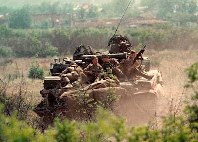
The two photos below show the two-layered engine deck opened up to expose the engine, ready to be serviced.


The T-72 was a true main battle tank, having successfully achieved an excellent compromise of the three principle attributes that govern basic tank design: firepower, protection and mobility. Throughout its career during the Cold War, the T-72 had one of the world's most powerful tank guns, had excellent armour protection, and was reasonably agile compared to its peers. In terms of average travelling speed, the off-road performance of the T-72 was broadly comparable to peers such as the M60A1, Chieftain and Leopard 1 but the T-72 had better acceleration characteristics. However, the T-72 was by no means the best in this category as the T-80 entered service only a few years later, followed by the Leopard 2 and then the M1 Abrams. All of these tanks surpassed the T-72 in acceleration characteristics and top speed by a significant margin, although it should be pointed out that "mobility" is an umbrella term that covers more than just these two aspects.
Compared to the T-64A from which it was created, the T-72 Ural is a heavier tank. This is despite having the same gun, a very similar weight of armour for both the hull and turret and virtually identical internal equipment. The culprit of this added weight is the running gear, which weighed a total of 6.2 tons in the T-64A but weighed 8.47 tons in the T-72. The difference of 2.27 tons is due to the heavier roadwheels, heavier tracks, heavier cooling system, and the enlarged volume of the engine compartment which required more armour to be added to the tank due to the increased surface area. These factors were counterbalanced by the installation of a more powerful V-shaped engine, thus placing the mobility of the T-72 on a marginally higher level than the T-64A.

Despite being heavier than the T-64A, the T-72 was still small and lightweight for a tank of its type. This simplified rail transportation and allowed it to safely cross low-capacity bridges and make good use of the large fleet of tactical bridge layers in Soviet army service, including the ones derived from the then-already-antiquated T-54.
Swedish mobility trials of T-72M1s (and MTLBs) in Northern Norrland between 1992 and 1994 yielded positive results. The tanks in question displayed good performance over snow as deep as 0.8 meters although it still failed at times to reliably traverse frozen ice banks.
Trenches with a width of 2.6-2.8 meters can be crossed either by driving slowly or at high speed. With the mud guards on, the T-72 can only climb vertical obstacles measuring at least 0.85 meters in height. When they are removed, the tank can scale obstacles at least as tall as 1.2 meters or more. This is despite such obstacles being not only taller than the idler, but also the top run of the tracks. For comparison, the M60A1 is only able to climb a 36" (914mm) vertical obstacle despite the much taller location of its idler wheel.
The engine deck consists of two panels - the engine access panel, and the radiator panel. The engine access panel is just a simple stamped steel plate, while the radiator panel is made as part of the intake ducting for the radiator packs held within. These two panels are hinged on a crossbar that spans the width of the engine compartment. Both panels are bolted to the hull structure along their perimeter, securing them tightly against unintended water ingress. If needed, the radiator access panel can be opened on its own, without also lifting the radiator pack. This may be done to clean the radiator pack of debris, leaves, etc.

Having the engine deck panels bolt firmly to the hull is inconvenient in terms of tedium when the panels need to be lifted for access, but in addition to water sealing, this type of engine deck enclosure allows the thick panels to serve as structural members of the hull. This provides the hull with better rigidity when subjected to a mine blast, nuclear explosion, and other similar stresses. Sectioned intake panels, as found on tanks such as the Centurion and Patton series, normally have only one of the panels screwed in place, while the others are secured by an overhanging lip from their neighbouring panel. This makes it much less tedious to open up large areas of the engine deck, but the lack of spring-loaded hinges to support the weight, and the lack of positive fastening, creating loose tolerances, are issues that are not to be neglected.
Each panel can be hinged open on its own, or both panels can be opened together. The minimum angle between the panels is 100 degrees, and as such, only one panel can be fully opened at any one time. To minimize the need for opening the access panels as much as possible, the engine oil, transmission oil and coolant filler ports have their own, separate access ports for oil and coolant checks. The entire engine deck can only be removed as part of an involved process, which involves unbolting not only the deck panels but also the crossbeam between them, and draining the cooling and lubrication systems to empty out the radiator packs, since quick-disconnect couplings were not used.


Removal of the entire engine deck is done only when it is necessary to replace major internal assemblies such as the engine, the intermediate power transfer gearbox, or the cooling fan mechanism, among others. Otherwise, all other components can be accessed and replaced after opening one of the two access panels. In the case of major powertrain repair or replacement, coupling the two access panels and the radiator pack together into a single unit speeds up the overall process to some extent, as this allows a 1.5-ton crane to remove all three units in one go.
An interesting feature of the tank is that when driving in peacetime, the external indicator lights of the T-72 can function as a road signalling system, including features such as a turn signal and brake light. An emergency signal can also be given, whereby all marker lights begin flashing. The road signalling system includes marker lights, the KDS 1-2C road signalling system box, an internal warning lamp and switches to activate the signals. The KDS 1-2C box houses the switches to turn the marker lights on and off, as well as activating the left and right turn signals, whereby the left and right marker lights flash until the switch is reset. It also activates the marker lights when the brake pedal is depressed, thus providing a brake light.
The T-72 has been host to several variations of the same type of engine over the years, starting with the V-46, evolving into the V-84, and finally the V-92. All of the T-72 engines to date are V-12 four-stroke diesels with a multifuel capability. They are able to consume low octane gasoline (A-66 and A-72), standard Soviet military-grade diesels, kerosene (TS-1, T-1 and T-2), and petroleum naphta (paint thinner). At temperatures of above 0°C, referred to as "summertime", the DL grade is used. At temperatures of between 0°C and -30°C, the DZ grade is used. At temperatures of between -30°C and -50°C, the special DA grade is used. The engine power falls by up to 20% when using petrol or kerosene.
The driver can switch the type of fuel between gasoline, diesel and jet fuel by simply setting a rotary selector located next to his seat. The engine does not need to be further modified beyond that, but it is inefficient when using petrol. All engines were fitted with the typical complement of accessories such as an oil preheater system, oil filters, and an ST-10-1S starter-generator. The ST-10-1S is a starter motor that doubles as the generator to power the electrical systems of the tank, using the principle of reversing a motor to use it as a generator. The operating speed of the ST-10-1S in the generator mode is between 3,600-6,250 RPM. The generator begins to output its rated power at the nominal electrical load at an engine speed of 900 RPM, and full operating power is achieved at 1,200 RPM. A fluid coupling was used to drive the device in the generator mode, requiring the crankshaft speed to be at least 80 RPM to produce enough oil pressure for the generator to begin producing electricity. When used as a starter motor, the electrical system boosts the input voltage to 48 V to provide the necessary starting power of 14.7 kW while keeping the current low, and thereby reduce the heat stress of the device. Because the ST-10-1s starter-generator is a DC generator, push-starting or tow-starting the T-72 is possible. The weight of all accessories is taken into account in the published weighs of the various engines fitted to T-72 models.
During the creation of the T-72 (Object 172M), the design and tuning of the V-46 engine was made so that the level of mobility would nominally correspond to that of the T-64A. The initial model Object 172 models designed by the UKBTM design bureau were made by converting existing T-64A hulls delivered from Kharkov, and were fitted with the V-45K engine with a power of 730 hp. Compared to the 5TDF engine of the T-64A, the power output was 30 hp higher, which was needed to compensate for the slightly increased weight of the tank (39 tons vs 38 tons) from the enlarged engine compartment. Following this, drastic changes made in the hull and suspension in the Object 172M design caused the weight of the tank to rise further from 39 tons to 41 tons, and to compensate for this, the V-46 engine was created, rated for 780 hp at 2,000 RPM. If viewed purely in terms of the power to weight ratio from the gross power of the engine, the T-72 was directly equivalent to the T-64A.
Due to a mandate by the government to standardize the T-72 transmission with the existing T-64A transmission, there was an inherent incompatibility between the engine speed of the engine and the gear ratios of the gearboxes, which would not have allowed the same top speed of 60 km/h to be achieved if the engine were directly connected to the gearboxes, as it was on the T-64A. To solve this issue, the input speed at the gearboxes was increased by a step-down gear in an intermediate power transfer gearbox between the engine and the gearboxes. This raised the input speed at the gearboxes from 2,000 RPM to 2,800 RPM, the same as in the T-64A. Even the powerband of the V-46 was matched to the 5TDF (at the gearbox input). In spite of this, the actual outcome of the switch to the V-46 resulted in a net gain in acceleration performance, because unlike the 5TDF, the V-46 moves from idle to its power band almost immediately due to the lower crankshaft speed of the engine itself.
The main method of starting the engine is via compressed air, with the possibility of electric starting or tow-starting as the auxiliary. Electric starting was not preferred as it added wear and tear to the starter-generator, which could lead to earlier electrical failure. In exceptionally cold weather conditions, the most dependable method of starting is a combination of compressed air and the electric starter. It takes around 20 minutes to start the engine in extremely cold weather, which is much longer than the 3 minutes needed by the GTD-1000T gas turbine engine used on the T-80, but diesel piston engines have their own advantages.
The compressed air is stored in a pair of 5-liter bottles installed in the nose of the hull glacis which are continuously maintained at the rated pressure by the AK-150SV compressor. The AK-150SV is a three-stage reciprocating compressor with air cooling. The compressor is powered via a power takeoff shaft from the intermediate power transfer gearbox ("Гитара"), so that it continues to run even if the tank is parked and the gearboxes are shifted to neutral. The gear ratio in the intermediate power transfer gearbox for the air compressor is 0.934. During normal operation, the compressor uses 1.1 to 2.2 kilowatts of power (1.47-2.95 hp) depending on the engine speed. As such, the compressor would reduce the net power delivered through the transmission by an average of around 2 hp when it is running. It has an operating pressure of 150 kg/sq.cm and a capacity of 2,400 liters per hour.
The compressed air bottles provide a reservoir of air for the engine starting system and serve as a source of air if the engine is not running. The pneumatic system of the tank is not only used to start the engine, but also to clean the driver's periscope, clean the gunner's primary sight, to evacuate the moisture and oil separator of the air compressor intake oil, clean the engine preheater by purging residue with a jet of compressed air, and for actuating electropneumatic valves to operate the filter-ventilator unit in the crew compartment. It is not known if the compressed air cylinders pose a tangible hazard if the tank armour is struck but not pierced. There is no doubt that the cylinders will explode if penetrated by a shaped charge jet or by heavy metal fragments, but the small size of the cylinders make that unlikely unless a very specific part of the front hull armour is hit.
In all T-72 models, the engine draws air from the engine compartment itself rather than from any particular intake. The main source of air in the engine compartment is sourced from the engine deck intake, but it is also possible for air to enter the engine compartment from the crew compartment. In this way, the air within the engine compartment always flows from the front to the back, i.e. in through the engine deck intake and the radiator intake, and out through the cooling fan. To minimize the amount of heat permeating around the air cleaner due to its close proximity to the radiator packs, there is an internal partition that separates the air cleaner unit from the cooling system airflow pathway. During winter, the engine deck intake is closed with a cover, thus making the engine air cleaner system induct heated air from the radiators instead. Cooling efficiency is also reduced somewhat, because some amount of heated air recirculates around the engine rather than exiting directly via the cooling fan, but this is desirable as it can help to warm up the auxiliary components.
The photo on the left below shows the engine access panel intake for T-72 models with a V-46 engine. The photo on the right below shows the intake for T-72 models with a V-84 engine. Unlike the intake at the same location on the preceding T-62, T-55 and T-54 tanks, this intake is nothing more than a hole in the engine access panel which permits air to enter the engine compartment. Because the cooling fan evacuates air inside the engine compartment, the engine compartment is constantly held at a negative temperature, and the resulting pressure differential serves as the main driving force for atmoshpheric air to enter the engine compartment via the engine deck intake, supplemented by the negative pressure from the air cleaner itself due to engine induction. Unlike the preceding T-62, T-55 and T-54 tanks, where all or almost all of the air needed by the engine is sourced from the radiator intakes, no air is taken from the radiator intakes on the T-72.
The air supply of the engine is processed by a two-stage air cleaner system with automatic dust ejection. It is virtually identical to the VTI-4 previously used on the T-54, T-55 and T-62, but features a number of modifications to support the nuances of the V-46 engine. According to V.S. Dubov, writing in the collection of memoirs "Life Given to Tanks", the increase in the air consumption of the engine in the Object 172 compared to the T-62 led to the need to develop a new air cleaner and required the development of a new dust extraction ejector. Before the new air cleaner was designed, deterioration was observed in the original air cleaner and dust ejection system after tests of the Object 172. When creating a new version of the dust ejector, the task was to find the required intake area of the nozzle and position it in the ejector body so that it minimally increased the hydrostatic pressure at the inlet and at the exhaust outflow. Hydrostatic pressure creates resistance, which must be overcome with the energy of the engine itself via its exhaust gasses. In this case, a higher resistance leads to a higher exhaust backpressure, which introduces a power loss.
The VTI-4 was developed at the VNII-100 research institute for medium tanks, with its first use being in the T-54 from 1953 and onwards. The only difference is that the purified air outlet is a single wide duct that connects to the supercharger intake of the V-46, rather than being two smaller ducts that feed into the engine cylinders as on preceding tanks.
A multi-cyclone cleaner is used as the first stage of the air filtration system, functioning as the main filtration unit. It consists of 96 micro-cyclones, with the collected dust falling into an ejection duct where it is carried away by the engine exhaust.

The dust ejection system uses the negative pressure of the engine exhaust to induce airflow in the dust collection pan, thereby sweeping the dust into the ehxaust outflow. This was done by having the engine exhaust manifolds routed to an exhaust duct where the high velocity exhaust creates a low pressure zone downstream of the exhaust. Each exhaust duct is also narrowed ahead of the exhaust stream to further increase exhaust velociy via the Venturi effect. The air in the dust collector underneath the cyclones, which is upstream of the exhaust, has a high static pressure. The pressure differential results in a flow of air from the dust collector into the exhaust ducts where the cool dusty air is mixed with the engine exhaust. The mixture then flows out of the exhaust port. This evacuates the dust within the dust collector and simultaneously cools down the exhaust gasses. The drawing below shows the exhaust ducts for both sides of the engine, linked to the two exhaust manifolds.

Specific details on the strength of the exhaust cooling effect are not known. If exploited properly, the induced airflow from engine exhaust via the Bernoulli principle tends to be very strong, and indeed, this was leveraged by the ejection-type cooling system of the PT-76, T-10 and T-64 series tanks, which lacked cooling fans, instead relying solely on the engine exhaust to induce a flow of air through their radiator packs at a sufficient rate for satisfactory driving performance. However, to use the energy of the exhaust for this purpose would incur power losses due to backpressure, which is the source of the cooling system losses in the aforementioned tanks. And indeed, the VTI-4 air cleaner generates an exhaust resistance of 11.8 kPa, more than twice as high as foreign tank engine exhaust systems (~5 kPa). Due to intense efforts made in reducing power losses, the exhaust resistance of the T-72 is less than that of preceding medium tanks, but still remains higher than foreign tanks. This is, however, largely unavoidable, and would be encountered by any tank equipped with an exhaust cooler for thermal signature suppression purposes. The most common form of exhaust cooler is a venturi ejector, as shown in the drawing below, taken from the "Engineering Design Handbook: Military Vehicle Power-plant Cooling".
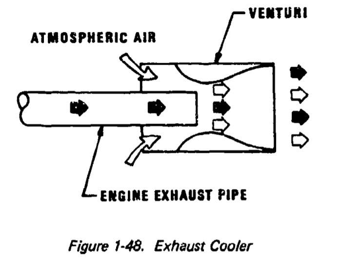
The dust ejection system may also promote better engine aspiration because it generates a flow of air towards the air cleaner. The intensity of the airflow changes dynamically with the exhaust output, which is dependent on the engine speed. As such, when the engine load rises and falls, both the exhaust cooling and intake airflow will rise and fall accordingly.
An additional nuance to note regarding the exhaust cooling effect is that because the exhaust is cooled after leaving the manifolds and entering the exhaust ducts, the duct surfaces and the exhaust gasses themselves are too cool to evaporate fuel for the engine smokescreening system. As such, the fuel injectors had to be placed at the end of the manifolds, so that the diesel can be evaporated into an aerosol and then cooled as it enters the exhaust ducts, where it condenses and becomes smoke.
Due to the lack of moving parts in cyclone filters, and the use of gas suction from the engine exhaust to continuously extract the collected dust, the cyclone system has very low maintenance demands. Even as a pre-filter, the cyclone system handles the bulk of the filtration workload, providing an air purity of at least 99.4% on its own. The second stage is a fine filtration system comprised of three steel mesh filter cassettes of progressively finer meshes. These cassettes are oil filters, with the meshes being coated with a thin layer of engine oil by soaking before being loaded into the air cleaner unit. After passing through the second filter stage, an air purity of no less than 99.8% is achieved. The nominal dust transmission rate through the specific air cleaner model used in the T-72 is unknown, the nominal dust transmission rate through the VTI-4 is 0.078%, with an airflow rate of 472 liters per second.
After passing through the last filter cassette, the main flow of air enters the supercharger of the engine via a large outlet duct, and some air is diverted out via a secondary air hose into the AK-150 air compressor, where it is used to refill the pneumatic reservoirs of the tank.
When the air intake resistance crosses a certain threshold, indicating clogged filter elements, a sensor is tripped and the driver is notified by a warning light on his instrument panel. After the warning light comes on, the tank is allowed to be driven for an additional 5 hours under conditions of medium air dustiness or 2 hours under conditions of high air dustiness. The nominal time between servicing under a standard air dust density of 2.5 grams per cubic meter (high dustiness in desert environment) is 400 km according to the research paper "Высокоэффективная система очистки воздуха для военных гусеничных машин" by M.D Borisyuk et al.. According to Sergey Suvorov in "Танки Т-72: Вчера, Сегодня, Завтра", the air cleaner requires cleaning every 1,000 km in winter, and every 500 km in the summer.
Before cleaning the filter elements, the engine access panel is first opened, then the filter unit top cover is opened, and the retaining brackets are removed. Each of these steps involves unscrewing bolts, which is rather tedious. The elements can then be removed.


Cleaning of the filter elements in field conditions is done by hosing them down with a jet of diesel, which is made possible by the inclusion of an MZA-3 fuel filler device in the accessories kit of the T-72. The MZA-3 is a powerful, compact device that can pump out diesel at 60 liters per minute. By connecting it to the fuel of the tank, and connecting its power cable to the external ShR-51 electrical socket on the left rear corner of the T-72 hull, the crew can set up a washing station next to the tank. The elements are then coated with engine oil before being reinstalled.
The engine deck is cool enough that people can ride on top of it.

The two photos below show the two-layered engine deck opened up to expose the engine, ready to be serviced.


V-46 (V-46-4, V-46-6)
 The
V-46 is a liquid-cooled supercharged diesel engine. It is a V12 engine with a 60-degree V-angle. The V-46 was developed in Chelyabinsk by the Chelyabinsk Tractor Plant (ChTZ) as a modern derivative of the classic V-2 which once powered the iconic T-34 and KV-1, but is otherwise a completely new design. In general, the V-46 and all its descendants are robust and dependable multifuel diesel engines that offer good performance for a tank in the weight class of the T-72. The V-46 produces 780 hp (574 kW) at a rated speed of 2,000 RPM. The engine is rated for a temperature range of -40°C to +50°C. Without preheating, the minimum starting temperature is +5°C.
The
V-46 is a liquid-cooled supercharged diesel engine. It is a V12 engine with a 60-degree V-angle. The V-46 was developed in Chelyabinsk by the Chelyabinsk Tractor Plant (ChTZ) as a modern derivative of the classic V-2 which once powered the iconic T-34 and KV-1, but is otherwise a completely new design. In general, the V-46 and all its descendants are robust and dependable multifuel diesel engines that offer good performance for a tank in the weight class of the T-72. The V-46 produces 780 hp (574 kW) at a rated speed of 2,000 RPM. The engine is rated for a temperature range of -40°C to +50°C. Without preheating, the minimum starting temperature is +5°C.
The V-46-4 model was used on the T-72 Ural and most other T-72 variants, and the V-46-6, which was first tested in 1976 in the Object 176 experimental tank, was used in the T-72A. Overall, seven modifications of the V-46 engine were made with a range of power ratings from 650 hp to 780 hp. They were installed in T-72 tanks, engineering vehicles based on it, modernized T-55AM and T-62M tanks, self-propelled artillery vehicles, SHORAD systems, and other military tracked vehicles totaling 20 types. The main downside of the V-46 is that it has a high specific oil consumption rate of 8 g/hp.h, which is a trait shared with other V-2 derivatives. This is mainly due to the relatively large clearances in the cylinder group, which is an indication of the state of manufacturing technologies available in the Soviet Union.
It has a large bore diameter of 150mm and a piston stroke length of 180mm (left cylinder group) and 186mm (right cylinder group), which is the same as the V-2. The right cylinder bank has a capacity of 19.8 liters and the left bank has a capacity of 19.092 liters, and the total capacity is 38.89 liters. This is usually abbreviated to 38.8 l. The asymmetric cylinder banks was a result of using master-and-slave connecting rods, with the right piston having the slave, or articulated, connecting rod. This allowed the engine length to be minimized, which was not only beneficial in terms of compactness, but also reduced its weight, as the material savings from having a shorter engine block meant less weight. This is in contrast to conventional automotive V-engines which usually have side-by-side connecting rods, which generally increases engine length by 11-14% and introduces additional bending moments that bend the crankpin due to the longitudinal offset between the connecting rods in each pair, increasing stress.
All of the basic features of the V-46 were inherited directly from the original V-2, including its dual overhead camshaft and variable speed mechanical governor. At the time the V-2 was introduced, these were modern features, but by the time the T-72 was introduced, both features had long become standard among tank engines. The firing order of the engine is 1-12-5-8-3-10-6-7-2-11-4-9, or 1L-6R-5L-2R-3L-4R-6L-1R-2L-5R-4L-5R. The camshaft pairs on both cylinder banks are identical and provide symmetrical valve timing. Injection timing is also symmetrically matched on both sides. Although the right groups of pistons has a longer stroke, the torque delivered is equal between the two piston groups. Altogether, the V-46 corresponds to an ideal even-firing 60-degree V12 engine, with full dynamic balance without needing balancing shafts.
The V-46 was designed with a large valve overlap of 75 degrees, which provides a strong scavenging effect as the negative pressure from the leaving exhaust gasses are used to accelerate the entry of fresh air into the cylinder. This was an important design change from earlier V-2 engine derivatives, which had a small valve overlap of less than 20 degrees. It functions as a means of completely purging exhaust gasses from the cylinder, and it also provides significant air cooling to the piston head and injector nozzle. The large valve overlap works in tandem with the supercharger to increase engine power, at the expense of creating excessive gaps at idling speeds which reduces fuel economy, owing to the fixed valve timing. According to operational guidelines, the engine should idle at a speed of 800-900 RPM (no less than 800 RPM), and the minimum idle speed is 600 RPM, which is the minimum stable crankshaft speed, but idling at 600 RPM is not recommended. On previous V-2 derivatives, the recommended idle speed was 600 RPM due to the lack of a significant valve overlap.
A variable speed mechanical governor is capable of setting a variable idle speed, to enforce a fixed maximum speed, and to maintain any constant speed between idle and maximum. The driver is provided with two controls to regulate fuel - the hand accelerator, used to set the idle speed which is then automatically maintained by the governor, and the accelerator pedal, which is used to manually increase the engine speed, which the governor will maintain under fluctuating loads by increasing or decreasing the fuel flow in response. If, for example, the driver is keeping his foot on the accelerator pedal at a steady position to maintain an engine speed of 1,900 RPM, then as the tank travels across undulating terrain, the governor will maintain the same engine speed even as the engine load rises when the tank is climbing a mound and then falls as the tank rolls down the opposite side of the mound. Because the engine speed is constant, the tank speed also remains constant, making it easier for the driver to control the tank and increasing the average speed of the tank during cross-country operation.
Setting the idle speed is done before starting the engine by pushing the hand accelerator to the idle position. The hand accelerator handle knob is shown in the photo below, next to the steering handle and behind the GPK-59 gyrocompass.
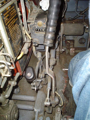
Idling at the 600 RPM minimum speed is possible with the hand accelerator, but not recommended. Idling at an excessively low speed is not conducive to fuel economy, and promotes soot buildup. The recommended idling speed of at least 800 RPM is set by the driver during engine startup by pushing the hand accelerator until resistance is felt, which will be around the middle of the accelerator handle pawl. The handle can be pushed forward beyond the felt resistance to increase the idling speed of the engine to charge the batteries at a quicker rate, when preheating the engine and to keep the engine warm in cold weather, when running the engine on a fuel other than diesel, when the stabilizer needs to be fully powered, and so on. The driver has to observe the tachometer while pushing the handle forward until he observes that the desired speed has been reached, or if a certain voltage is needed, he needs to observe the voltmeter. For example, to reach and sustain 26 V to supply the nominal rated power to the stabilizer, the engine speed should be 1,500-1,600 RPM. When shutting off the engine, the hand accelerator is pulled to the full rear position to cut off the fuel supply.
The N-46 centrifugal supercharger is used on all models of the V-46 series. The air intake of the supercharger is above the end of the crank shaft. It is connected to the air intake filtration unit by a duct. On the opposite end of the engine is the exhaust manifold exit ducts and the air distributor hub of the pneumatic starting system.

The compression ratio is 14. This ratio is relatively low, but remained within permissible limits for a compression ignition engine because the N-46 supercharger generates a sufficiently high boost pressure of 0.68 bar (0.7 kgf/sq.cm). The total overpressure within the cylinder is 0.804 bar (0.82 kgf/sq.cm) - higher than the supercharger boost pressure alone thanks to the scavenging provided by the valve overlap. The overall pressure, which is inclusive of atmospheric pressure, is therefore 1.817 bar at sea level. The air temperature inside the cylinder at the end of the intake stroke is 128°C. It is because of the high boost provided by the supercharger and scavenging that the fuel efficiency remains relatively high, despite the somewhat low compression ratio. The specific fuel consumption is 180 g/hp.h at the rated speed, which is the same as the V-55 and AVDS-1790-2 series engines, and lower than the 185 g/hp.h of the MB 838 CaM-500. The minimum specific fuel consumption is around 172 g/hp.h.
Thanks to the use of a cast aluminium engine block, the engine weighs just 980 kg. Its compactness gives the V-46 an exceptionally high specific power of 653 hp/cu.m. Its mean effective pressure (MEP) is 8.8 bar (9 kgf/sq.cm).
As the capacity of the engine is 38.8 liters, which is quite large relative to the power output of the V-46, the engine has a power density of 20.1 hp/l. This is considerably lower than the MB 838 CaM-500 powering the Leopard 1 (22.2 hp/l) and the AVDS-1790-2C powering the M60A1 (25.5 hp/l), but the large displacement of the engine - primarily the long stroke length of the pistons - is responsible for the favourable torque output of the engine and its competitive specific torque. The operating speed range of the engine is 1,300-2,000 RPM, and the maximum crankshaft speed is 2,300 RPM.
The idle speed of the V-46 is the same as the 5TDF, but because to the step-up gear in the intermediate power transfer gearbox, the idle speed at the BKP input is actually around 1,100-1,200 RPM. The maximum torque output is 3,090 Nm at an engine speed of 1,300 RPM, dropping to 2,745 Nm at 2,000 RPM. Based on the known torque curve of the Polish S-1000 engine, an uprated derivative of the V-46-6, it can be calculated that the torque of the engine at a speed of just 1,000 RPM is only 2.5% below the peak torque. Thus, the torque curve should be as follows:

As the graph shows, the low end of the torque curve is extremely flat, and an enormous amount of torque is obtained even at 1,000 RPM, just marginally higher than the idle speed. In practical terms, this means that the driver of a T-72 has a great deal of power delivered immediately upon stepping on the accelerator pedal, which translates to exceptional driving response. This is not only significant as a measure of responsiveness, but it shows that lowering the speed at which the engine develops peak torque was utilized as the method of improving engine flexibility.
To quantify the qualities of the engine dynamics, two metrics are used - engine flexibility (adaptability) and engine elasticity. The engine flexibility (adaptability) coefficient is 1.125, which is otherwise known as the torque backup, torque reserve or torque rise when expressed as a percentage. In this case it is 12.5%. Strangely enough, officially, the torque backup of the V-46 is rated as 9-18%, which is obviously not achieved with the given maximum torque and torque at maximum power. This places the V-46 between the MB 838 CaM-500, the 5TDF, and the MB 873 Ka-501 engine in terms of engine flexibility. The MB 838 CaM-500 has a mere coefficient of 1.058 (5.8% torque backup) while the 5TDF engine reaches a more respectable coefficient of 1.095 (9.5% torque backup), whereas the MB 873 has an engine flexibility coefficient of 1.159 (15.9% torque backup). The AVDS-1790-2 series is by far the worst, with a coefficient of just 1.041 (4.1% torque backup). High engine flexibility is important for negotiating terrain that imposes high fluctuating engine loads rather than constant loads, and is therefore responsible for providing a high cross-country speed.
Additionally, to quantify the characteristics of the power band, the engine elasticity coefficient is used. The wider the power band, the lower (better) the coefficient. For the V-46, the coefficient is 0.65, slightly lower (better) than the MB 838 CaM-500 of the Leopard 1 (0.68) substantially lower than the 5TDF (0.73) but slightly higher (worse) than the MB 873 Ka-501 of the Leopard 2 (0.61). Again, the AVDS-1790-2 series performs the worst by far, with an elasticity coefficient of 0.75 (using peak torque speed of 1,800 RPM from Hunnicutt) or 0.79 (using peak torque speed of 1,900 RPM from Teledyne). But even this was already better than the earlier AV-1790-7 series gasoline engine that powered the later M47s and M48s, as that had a ghastly elasticity coefficient of 0.857. A wide power band contributes to the ease of driving the tank in various types of terrain, because it means that downshifting is often not necessary when the tank slows down as the engine produces a large amount of power at a wide range of speeds.
It is worth noting that the peak torque speeds in the chart differ slightly from the official rating, as it shows that peak torque begins at 1,200 and it is maintaned up to 1,400 RPM. This is excellent as the high peak torque is available at a wide range of low engine speeds, so the engine is able to provide a large amount of tractive force to overcome resistances which is necessary for accelerating a heavy vehicle like a tank from a standstill, while the flatness of the torque curve translates to a large amount of power available even at a low engine speed, which ensures that high acceleration performance is achieved and maintained across the power curve. Compared to the 5TDF, the fact that the peak torque of the V-46 is achieved at a much lower engine speed of 1,300 RPM rather than 2,050 RPM gives an advantage in load-bearing characteristics and in acceleration performance, given that both engines idle at 800 RPM. Taking into account the step-up gear, the input speed at the BKPs from the V-46 engine is 1,183 RPM at idle and 1,840 RPM at peak torque. The 5TDF, on the other hand, must accelerate from 800 RPM to 2,050 RPM. Proportionately speaking, the power band of the V-46 starts at a lower engine speed, and the power band is correspondingly wider.

In the power curve illustrated above, it can be seen that the engine develops 605 hp at 1,400 RPM. For comparison, the AVDS-1790-2 engine series for the M60A1 and M60A3 (among others) manages an output of 486 hp (480 bhp) at the same speed. The difference in low end power is 119 hp - much greater than the difference in the peak powers developed by the two engines, 780 hp compared to the 760 hp (750 bhp) of the AVDS-1790-2 series. This is due to the large deficiency in engine elasticity that the AVDS-1790-2 series suffers from, and it means that despite having a higher rated power output, an AVDS-1790-2 series engine needs to be driven harder under most circumstances to produce the same amount of power as the V-46. Furthermore, when measured by sprocket power, the power developed by the V-46 is actually at the same level as the MB 838 CaM-500 engine of the Leopard 1 which has a much higher rated power output of 830 hp, even exceeding it at lower engine speeds thanks to the high torque developed by the V-46. And finally, although the V-46 does not surpass these two engines in power and torque density to a noteworthy degree, its light weight and small overall size give it favourable power and torque density characteristics.
However, the V-46 is soundly beaten by the advanced MB 873 Ka-501 of the Leopard 2 which has a maximum power output of 1,500 hp and generates a maximum torque of 4,700 Nm at 1,600 RPM. Of course, this is not particularly surprising because the MB 873 is a larger 47.6-liter engine. The light weight of the T-72 only compensates for this to some extent. In terms of handling torque overloads during steady driving, such as when maintaining a cruising speed over rough terrain, when operating a mine plough, when driving over obstacles, up a hill, towing another tank, and so on, the V-46 performs well thanks to a large torque backup of 12.5% and therefore, a good engine flexibility. Having a low peak torque speed of 1,300 RPM and a high torque backup allows the V-46 to provide good acceleration characteristics and retain driving performance when moving in difficult terain.
Officially, the maximum permissible operating altitude of the V-46 is 3,000 meters. However, Indian forces deployed in the icy mountainous regions of Eastern Ladakh have been successfully operating their T-72M1 tanks at altitudes in excess of 4,500 meters.
V-46 engines delivered to the Soviet Army had a warranty service life of 500 engine hours. The actual service life regularly exceeded the warranty service life. After going through an overhaul, the factory guaranteed an additional 300 engine hours of operation, providing a total warrantied service life of 800 hours, with the service life defined as the 90% exhaustion of its total life. According to a large-scale East German study of the reliability of East German and Czechoslovak T-72M tanks, the useful lifetime of the engine reaches 800 engine hours. Officially, 800 engine hours is considered equivalent to 9,000-10,000 km of travel. For comparison, Simon Dunstan states in "Chieftain Main Battle Tank 1965-2003" that the planned engine service life of the Leyland L60 engine targeted by the "Sundance" reliability improvement programme (1976-1979) was 4,000 miles (~6,400 km), but even this modest goal was rarely achieved despite the maturity of the engine and the tank itself by the time of the "Sundance" programme. This was equivalent to the average lifespan of a V-2 engine (T-34-85) produced in 1944-1945 and would have been considered blatantly unacceptable in the postwar era.
The exhaust port for this engine is characteristically long and narrow, because the exhaust manifolds from both sides of the engine were joined together just before exiting the exhaust port. It has very rudimentary sheet steel cooling fins on top. The fins are arranged so that as the tank drives forward, cool air rushes from one side of the fins to the other, drawing away some heat along the way.


The exhaust port connects to the exhaust manifold via a simple duct. The exhaust port is secured onto the duct via a pair of bolts and nuts on either side.

The V-46-4 is the variant which the T-72 Ural uses, while the V-46-6 is used in the T-72A. The only difference between the V-46-4 and the V-46-6 is a change in the placement of oil containers. With the V-46, both the T-72 Ural and T-72A can achieve a nominal top speed of 60 km/h on asphalt and set an average speed of 35 to 40 km/h on dirt roads.
The
V-46 is a liquid-cooled supercharged diesel engine. It is a V12 engine with a 60-degree V-angle. The V-46 was developed in Chelyabinsk by the Chelyabinsk Tractor Plant (ChTZ) as a modern derivative of the classic V-2 which once powered the iconic T-34 and KV-1, but is otherwise a completely new design. In general, the V-46 and all its descendants are robust and dependable multifuel diesel engines that offer good performance for a tank in the weight class of the T-72. The V-46 produces 780 hp (574 kW) at a rated speed of 2,000 RPM. The engine is rated for a temperature range of -40°C to +50°C. Without preheating, the minimum starting temperature is +5°C.The V-46-4 model was used on the T-72 Ural and most other T-72 variants, and the V-46-6, which was first tested in 1976 in the Object 176 experimental tank, was used in the T-72A. Overall, seven modifications of the V-46 engine were made with a range of power ratings from 650 hp to 780 hp. They were installed in T-72 tanks, engineering vehicles based on it, modernized T-55AM and T-62M tanks, self-propelled artillery vehicles, SHORAD systems, and other military tracked vehicles totaling 20 types. The main downside of the V-46 is that it has a high specific oil consumption rate of 8 g/hp.h, which is a trait shared with other V-2 derivatives. This is mainly due to the relatively large clearances in the cylinder group, which is an indication of the state of manufacturing technologies available in the Soviet Union.
It has a large bore diameter of 150mm and a piston stroke length of 180mm (left cylinder group) and 186mm (right cylinder group), which is the same as the V-2. The right cylinder bank has a capacity of 19.8 liters and the left bank has a capacity of 19.092 liters, and the total capacity is 38.89 liters. This is usually abbreviated to 38.8 l. The asymmetric cylinder banks was a result of using master-and-slave connecting rods, with the right piston having the slave, or articulated, connecting rod. This allowed the engine length to be minimized, which was not only beneficial in terms of compactness, but also reduced its weight, as the material savings from having a shorter engine block meant less weight. This is in contrast to conventional automotive V-engines which usually have side-by-side connecting rods, which generally increases engine length by 11-14% and introduces additional bending moments that bend the crankpin due to the longitudinal offset between the connecting rods in each pair, increasing stress.
All of the basic features of the V-46 were inherited directly from the original V-2, including its dual overhead camshaft and variable speed mechanical governor. At the time the V-2 was introduced, these were modern features, but by the time the T-72 was introduced, both features had long become standard among tank engines. The firing order of the engine is 1-12-5-8-3-10-6-7-2-11-4-9, or 1L-6R-5L-2R-3L-4R-6L-1R-2L-5R-4L-5R. The camshaft pairs on both cylinder banks are identical and provide symmetrical valve timing. Injection timing is also symmetrically matched on both sides. Although the right groups of pistons has a longer stroke, the torque delivered is equal between the two piston groups. Altogether, the V-46 corresponds to an ideal even-firing 60-degree V12 engine, with full dynamic balance without needing balancing shafts.
The V-46 was designed with a large valve overlap of 75 degrees, which provides a strong scavenging effect as the negative pressure from the leaving exhaust gasses are used to accelerate the entry of fresh air into the cylinder. This was an important design change from earlier V-2 engine derivatives, which had a small valve overlap of less than 20 degrees. It functions as a means of completely purging exhaust gasses from the cylinder, and it also provides significant air cooling to the piston head and injector nozzle. The large valve overlap works in tandem with the supercharger to increase engine power, at the expense of creating excessive gaps at idling speeds which reduces fuel economy, owing to the fixed valve timing. According to operational guidelines, the engine should idle at a speed of 800-900 RPM (no less than 800 RPM), and the minimum idle speed is 600 RPM, which is the minimum stable crankshaft speed, but idling at 600 RPM is not recommended. On previous V-2 derivatives, the recommended idle speed was 600 RPM due to the lack of a significant valve overlap.
A variable speed mechanical governor is capable of setting a variable idle speed, to enforce a fixed maximum speed, and to maintain any constant speed between idle and maximum. The driver is provided with two controls to regulate fuel - the hand accelerator, used to set the idle speed which is then automatically maintained by the governor, and the accelerator pedal, which is used to manually increase the engine speed, which the governor will maintain under fluctuating loads by increasing or decreasing the fuel flow in response. If, for example, the driver is keeping his foot on the accelerator pedal at a steady position to maintain an engine speed of 1,900 RPM, then as the tank travels across undulating terrain, the governor will maintain the same engine speed even as the engine load rises when the tank is climbing a mound and then falls as the tank rolls down the opposite side of the mound. Because the engine speed is constant, the tank speed also remains constant, making it easier for the driver to control the tank and increasing the average speed of the tank during cross-country operation.
Setting the idle speed is done before starting the engine by pushing the hand accelerator to the idle position. The hand accelerator handle knob is shown in the photo below, next to the steering handle and behind the GPK-59 gyrocompass.

Idling at the 600 RPM minimum speed is possible with the hand accelerator, but not recommended. Idling at an excessively low speed is not conducive to fuel economy, and promotes soot buildup. The recommended idling speed of at least 800 RPM is set by the driver during engine startup by pushing the hand accelerator until resistance is felt, which will be around the middle of the accelerator handle pawl. The handle can be pushed forward beyond the felt resistance to increase the idling speed of the engine to charge the batteries at a quicker rate, when preheating the engine and to keep the engine warm in cold weather, when running the engine on a fuel other than diesel, when the stabilizer needs to be fully powered, and so on. The driver has to observe the tachometer while pushing the handle forward until he observes that the desired speed has been reached, or if a certain voltage is needed, he needs to observe the voltmeter. For example, to reach and sustain 26 V to supply the nominal rated power to the stabilizer, the engine speed should be 1,500-1,600 RPM. When shutting off the engine, the hand accelerator is pulled to the full rear position to cut off the fuel supply.
The N-46 centrifugal supercharger is used on all models of the V-46 series. The air intake of the supercharger is above the end of the crank shaft. It is connected to the air intake filtration unit by a duct. On the opposite end of the engine is the exhaust manifold exit ducts and the air distributor hub of the pneumatic starting system.

The compression ratio is 14. This ratio is relatively low, but remained within permissible limits for a compression ignition engine because the N-46 supercharger generates a sufficiently high boost pressure of 0.68 bar (0.7 kgf/sq.cm). The total overpressure within the cylinder is 0.804 bar (0.82 kgf/sq.cm) - higher than the supercharger boost pressure alone thanks to the scavenging provided by the valve overlap. The overall pressure, which is inclusive of atmospheric pressure, is therefore 1.817 bar at sea level. The air temperature inside the cylinder at the end of the intake stroke is 128°C. It is because of the high boost provided by the supercharger and scavenging that the fuel efficiency remains relatively high, despite the somewhat low compression ratio. The specific fuel consumption is 180 g/hp.h at the rated speed, which is the same as the V-55 and AVDS-1790-2 series engines, and lower than the 185 g/hp.h of the MB 838 CaM-500. The minimum specific fuel consumption is around 172 g/hp.h.
Thanks to the use of a cast aluminium engine block, the engine weighs just 980 kg. Its compactness gives the V-46 an exceptionally high specific power of 653 hp/cu.m. Its mean effective pressure (MEP) is 8.8 bar (9 kgf/sq.cm).
As the capacity of the engine is 38.8 liters, which is quite large relative to the power output of the V-46, the engine has a power density of 20.1 hp/l. This is considerably lower than the MB 838 CaM-500 powering the Leopard 1 (22.2 hp/l) and the AVDS-1790-2C powering the M60A1 (25.5 hp/l), but the large displacement of the engine - primarily the long stroke length of the pistons - is responsible for the favourable torque output of the engine and its competitive specific torque. The operating speed range of the engine is 1,300-2,000 RPM, and the maximum crankshaft speed is 2,300 RPM.
The idle speed of the V-46 is the same as the 5TDF, but because to the step-up gear in the intermediate power transfer gearbox, the idle speed at the BKP input is actually around 1,100-1,200 RPM. The maximum torque output is 3,090 Nm at an engine speed of 1,300 RPM, dropping to 2,745 Nm at 2,000 RPM. Based on the known torque curve of the Polish S-1000 engine, an uprated derivative of the V-46-6, it can be calculated that the torque of the engine at a speed of just 1,000 RPM is only 2.5% below the peak torque. Thus, the torque curve should be as follows:

As the graph shows, the low end of the torque curve is extremely flat, and an enormous amount of torque is obtained even at 1,000 RPM, just marginally higher than the idle speed. In practical terms, this means that the driver of a T-72 has a great deal of power delivered immediately upon stepping on the accelerator pedal, which translates to exceptional driving response. This is not only significant as a measure of responsiveness, but it shows that lowering the speed at which the engine develops peak torque was utilized as the method of improving engine flexibility.
To quantify the qualities of the engine dynamics, two metrics are used - engine flexibility (adaptability) and engine elasticity. The engine flexibility (adaptability) coefficient is 1.125, which is otherwise known as the torque backup, torque reserve or torque rise when expressed as a percentage. In this case it is 12.5%. Strangely enough, officially, the torque backup of the V-46 is rated as 9-18%, which is obviously not achieved with the given maximum torque and torque at maximum power. This places the V-46 between the MB 838 CaM-500, the 5TDF, and the MB 873 Ka-501 engine in terms of engine flexibility. The MB 838 CaM-500 has a mere coefficient of 1.058 (5.8% torque backup) while the 5TDF engine reaches a more respectable coefficient of 1.095 (9.5% torque backup), whereas the MB 873 has an engine flexibility coefficient of 1.159 (15.9% torque backup). The AVDS-1790-2 series is by far the worst, with a coefficient of just 1.041 (4.1% torque backup). High engine flexibility is important for negotiating terrain that imposes high fluctuating engine loads rather than constant loads, and is therefore responsible for providing a high cross-country speed.
Additionally, to quantify the characteristics of the power band, the engine elasticity coefficient is used. The wider the power band, the lower (better) the coefficient. For the V-46, the coefficient is 0.65, slightly lower (better) than the MB 838 CaM-500 of the Leopard 1 (0.68) substantially lower than the 5TDF (0.73) but slightly higher (worse) than the MB 873 Ka-501 of the Leopard 2 (0.61). Again, the AVDS-1790-2 series performs the worst by far, with an elasticity coefficient of 0.75 (using peak torque speed of 1,800 RPM from Hunnicutt) or 0.79 (using peak torque speed of 1,900 RPM from Teledyne). But even this was already better than the earlier AV-1790-7 series gasoline engine that powered the later M47s and M48s, as that had a ghastly elasticity coefficient of 0.857. A wide power band contributes to the ease of driving the tank in various types of terrain, because it means that downshifting is often not necessary when the tank slows down as the engine produces a large amount of power at a wide range of speeds.
It is worth noting that the peak torque speeds in the chart differ slightly from the official rating, as it shows that peak torque begins at 1,200 and it is maintaned up to 1,400 RPM. This is excellent as the high peak torque is available at a wide range of low engine speeds, so the engine is able to provide a large amount of tractive force to overcome resistances which is necessary for accelerating a heavy vehicle like a tank from a standstill, while the flatness of the torque curve translates to a large amount of power available even at a low engine speed, which ensures that high acceleration performance is achieved and maintained across the power curve. Compared to the 5TDF, the fact that the peak torque of the V-46 is achieved at a much lower engine speed of 1,300 RPM rather than 2,050 RPM gives an advantage in load-bearing characteristics and in acceleration performance, given that both engines idle at 800 RPM. Taking into account the step-up gear, the input speed at the BKPs from the V-46 engine is 1,183 RPM at idle and 1,840 RPM at peak torque. The 5TDF, on the other hand, must accelerate from 800 RPM to 2,050 RPM. Proportionately speaking, the power band of the V-46 starts at a lower engine speed, and the power band is correspondingly wider.

In the power curve illustrated above, it can be seen that the engine develops 605 hp at 1,400 RPM. For comparison, the AVDS-1790-2 engine series for the M60A1 and M60A3 (among others) manages an output of 486 hp (480 bhp) at the same speed. The difference in low end power is 119 hp - much greater than the difference in the peak powers developed by the two engines, 780 hp compared to the 760 hp (750 bhp) of the AVDS-1790-2 series. This is due to the large deficiency in engine elasticity that the AVDS-1790-2 series suffers from, and it means that despite having a higher rated power output, an AVDS-1790-2 series engine needs to be driven harder under most circumstances to produce the same amount of power as the V-46. Furthermore, when measured by sprocket power, the power developed by the V-46 is actually at the same level as the MB 838 CaM-500 engine of the Leopard 1 which has a much higher rated power output of 830 hp, even exceeding it at lower engine speeds thanks to the high torque developed by the V-46. And finally, although the V-46 does not surpass these two engines in power and torque density to a noteworthy degree, its light weight and small overall size give it favourable power and torque density characteristics.
However, the V-46 is soundly beaten by the advanced MB 873 Ka-501 of the Leopard 2 which has a maximum power output of 1,500 hp and generates a maximum torque of 4,700 Nm at 1,600 RPM. Of course, this is not particularly surprising because the MB 873 is a larger 47.6-liter engine. The light weight of the T-72 only compensates for this to some extent. In terms of handling torque overloads during steady driving, such as when maintaining a cruising speed over rough terrain, when operating a mine plough, when driving over obstacles, up a hill, towing another tank, and so on, the V-46 performs well thanks to a large torque backup of 12.5% and therefore, a good engine flexibility. Having a low peak torque speed of 1,300 RPM and a high torque backup allows the V-46 to provide good acceleration characteristics and retain driving performance when moving in difficult terain.
Officially, the maximum permissible operating altitude of the V-46 is 3,000 meters. However, Indian forces deployed in the icy mountainous regions of Eastern Ladakh have been successfully operating their T-72M1 tanks at altitudes in excess of 4,500 meters.
V-46 engines delivered to the Soviet Army had a warranty service life of 500 engine hours. The actual service life regularly exceeded the warranty service life. After going through an overhaul, the factory guaranteed an additional 300 engine hours of operation, providing a total warrantied service life of 800 hours, with the service life defined as the 90% exhaustion of its total life. According to a large-scale East German study of the reliability of East German and Czechoslovak T-72M tanks, the useful lifetime of the engine reaches 800 engine hours. Officially, 800 engine hours is considered equivalent to 9,000-10,000 km of travel. For comparison, Simon Dunstan states in "Chieftain Main Battle Tank 1965-2003" that the planned engine service life of the Leyland L60 engine targeted by the "Sundance" reliability improvement programme (1976-1979) was 4,000 miles (~6,400 km), but even this modest goal was rarely achieved despite the maturity of the engine and the tank itself by the time of the "Sundance" programme. This was equivalent to the average lifespan of a V-2 engine (T-34-85) produced in 1944-1945 and would have been considered blatantly unacceptable in the postwar era.
The exhaust port for this engine is characteristically long and narrow, because the exhaust manifolds from both sides of the engine were joined together just before exiting the exhaust port. It has very rudimentary sheet steel cooling fins on top. The fins are arranged so that as the tank drives forward, cool air rushes from one side of the fins to the other, drawing away some heat along the way.


The exhaust port connects to the exhaust manifold via a simple duct. The exhaust port is secured onto the duct via a pair of bolts and nuts on either side.

The V-46-4 is the variant which the T-72 Ural uses, while the V-46-6 is used in the T-72A. The only difference between the V-46-4 and the V-46-6 is a change in the placement of oil containers. With the V-46, both the T-72 Ural and T-72A can achieve a nominal top speed of 60 km/h on asphalt and set an average speed of 35 to 40 km/h on dirt roads.
V-84 (V-84-1, V-84M, V-84MS)
 The V-84 engine represented the limit of the growth potential provided by superchargers for the engine design. Its power output of 840 hp lay on the boundary of diminishing returns, as further increasing the power also drove up the power losses to the supercharger to an exorbitant degree. The V-84 engine series began mass production in 1984 at the ChTZ motor plant. It differs from its predecessor
mainly by an increase in torque output within the same operating engine speed range, thus producing more power. The basic V-84 was not used in the T-72 models preceding the T-72B, though there is some evidence that "Improved T-72A" tanks built in 1984 were fitted with the new engine. The V-84-1, featuring an air intake heating system for winter starting, was the most numerous version of the engine, being used in the T-72B obr. 1985, and the improved V-84M was used in later T-72B models at the end of the 1980's. The V-84MS was used in T-72B models built or modernized in the 1990's, including T-72BA tanks. The V-84MS was also installed in the T-90 obr. 1992. The V-84 was completely interchangeable with the V-46 and shared a large number of parts, being a derivative of the V-46-6.
The V-84 engine represented the limit of the growth potential provided by superchargers for the engine design. Its power output of 840 hp lay on the boundary of diminishing returns, as further increasing the power also drove up the power losses to the supercharger to an exorbitant degree. The V-84 engine series began mass production in 1984 at the ChTZ motor plant. It differs from its predecessor
mainly by an increase in torque output within the same operating engine speed range, thus producing more power. The basic V-84 was not used in the T-72 models preceding the T-72B, though there is some evidence that "Improved T-72A" tanks built in 1984 were fitted with the new engine. The V-84-1, featuring an air intake heating system for winter starting, was the most numerous version of the engine, being used in the T-72B obr. 1985, and the improved V-84M was used in later T-72B models at the end of the 1980's. The V-84MS was used in T-72B models built or modernized in the 1990's, including T-72BA tanks. The V-84MS was also installed in the T-90 obr. 1992. The V-84 was completely interchangeable with the V-46 and shared a large number of parts, being a derivative of the V-46-6.
With the installation of the V-84-1 in the T-72B, a rise in the losses of net power available to propel the tank had to be solved by imroving the efficiency of the powertrain. M. L. Naumov, who worked as a research engineer in the UKBTM automotive department, states in the collection of memoirs "Life Given to Tanks" that during testing, it was found that after installing the V-84 engine in the T-72A tank for testing, the engine power was reduced by 13-14% and its fuel efficiency was reduced by 15% due to the additional power losses arising from the overloading of the powertrain, which was not designed to handle the increased power. To improve the net power available to the tank, a comprehensive study was made to reduce power losses from inducted air heating, air intake resistance, exhaust backpressure, and the efficiency of the cooling system. As a result, improved assemblies - fully interchangeable with the original models - were developed, thanks to which the net power rose by an additional 50-55 hp.
The V-84 series produces 840 hp at an engine speed of 2,000 RPM, and the maximum torque developed by the engine reaches 3,335 Nm at a speed of 1,300 RPM. The engine elasticity coefficient is 0.65. Thanks to the retention of the original V-46 engine dimensions, the specific power was increased from 653 hp/cu.m to 700 hp/cu.m. The same N-46-6 centrifugal supercharger from the V-46-6 engine was used. It provides a boost pressure of 0.68 bar (0.7 kgf/sq.cm).
The increased power offsets the added weight of the tanks that have it installed, namely Object 184 tanks which includes "Improved T-72A" tanks produced in 1984 and all T-72B models, allowing it to remain as nimble as its predecessors. There was no improvement in the peak sprocket power-to-weight ratio, however. One side effect of the added power is the increased heat output. Since the cooling fan for the radiator draws power directly from the engine, the increased heat is mostly eliminated, but more heat escapes from the exhaust manifolds. For the upgraded V-84-1 and V-84M models, an intake air heating device was included to facilitate the starting of the engine in cold weather conditions. This device, combined with the use of special low-viscosity oil, made it possible to start the engine at a temperature of -20°C without needing to be preheated first.
The specific fuel consumption of the V-84 is 182 g/hph at the rated speed. This is marginally more than the V-46 and marginally less than 184 g/hph and 185 g/hph consumption rate of the MB 873 Ka-501 and MB 838 CaM-500 respectively.
Output at rated speed: 840 hp
Rated speed: 2,000 rpm
Idle speed: 800 rpm
Fuel Consumption: 247 g/kWh or 182 g/hph
Torque backup: 6-18%
Weight: 1,020 kg
The dynamic characteristics of the V-84 is shown in the chart below, taken from a V-84 technical manual. The power output of the engine rises sharply from around 610 hp to 840 hp as the engine speed increases from 1,300 RPM to 2,000 RPM. At the same time, the relative fuel consumption rate drops to the lowest point of 171 g/hp.h at 1,600 RPM and rises to the highest point of 182 g/hp.h at the rated speed of 2,000 RPM.

As mentioned earlier, the maximum torque output of the V-84-1 is 3,335 Nm at an engine speed of 1,300 RPM. This is much more than 1,922 Nm produced by the 5TDF of the T-64BV but much less than the 4,395 Nm produced by the GTD-1250 of the T-80U and the 5,170 Nm of the AGT-1500 of the M1 Abrams. The increased weight of the T-72B compared to the T-72A was offset (with a surplus) by the higher torque output and better overall dynamic running characteristics of the V-84 engine such that the acceleration characteristics probably increased to the level of the T-72 Ural. When using TS-1, T-1 and T-2 jet fuel or A-72 gasoline, the maximum torque output of the V-84 engine is only 900 Nm at 1,300 RPM. As such, the tank accelerates very slowly and cannot climb steep slopes or overcome most natural obstacles, so it is not feasible to operate a T-72B (or any T-72) with non-diesel fuels during combat. As a rule, non-diesel fuels can only be used in emergencies when diesel is completely unavailable.
When running under normal conditions, the V-84 engine has excellent running characteristics like the V-46, which can be seen in its power curve, producing a very flat torque curve throughout its speed range, almost as flat as the V-46. To illustrate this, the graph on the left shows the torque curve of the V-84, taken from a technical manual. The graphs show that the torque output of the V-84 is at the maximum of 3,334 Nm at 1,300 RPM and steadily drops to 2,940 Nm at 2,000 RPM, which gives an engine flexibility (adaptability) coefficient of 1.13. In other words, the high torque generated by the engine is largely retained throughout a wide range of engine speeds, to almost the exact same extent as the V-46, albeit with a larger dropoff at the rated engine speed for peak power. The torque reserve of 11.8% is slightly higher (worse) than the V-46, again owing to the larger dropoff at peak power.

Thanks to its flat torque curve, the resulting power curve delivered by the V-84 was also flattened, gaining a more linear rise with engine speed, matching the V-46 power curve in shape. This is shown in the graph on the left below, produced using the power curves for both engines. Though the overall performance across the power curve was still largely the same, there is a slight difference in the sprocket power-to-weight ratio due to the V-84 power curve. The V-84 is able to maintain an identical sprocket power-to-weight ratio on the T-72B only on the lower half of the operating speed range, but because the torque curve has a larger gradient at the tail end of the range, the peak sprocket power-to-weight ratio actually worsened slightly.


Nevertheless, this is not unsurprising given that the engine is functionally the same aside from the increased torque. When compared to an equivalent diesel engine of a similar power, the flatness of the torque curve still gives the V-84 a great advantage in that it produces a stronger and more uniform acceleration from a standstill, as illustrated in the two graphs below - the top graph shows the power curve of the V-84, and the bottom graph shows the power curve of the MB-838, the engine of the Leopard 1. At an engine speed of 1,300 RPM, the V-84 puts out just a little over 441 kW (600 hp) of power, whereas the MB-838 generates around 380 kW (516 hp). In this case, the difference in low end power is nearly 100 hp, an important gap which would be missed if the two engines were compared purely in terms of peak power output (840 hp vs 830 hp). This gap of 100 hp is still maintained at an engine speed of 1,500 RPM, which is the point where the MB 838 develops its maximum torque. From there, the gap gradually diminishes as the engine speeds increase, narrowing to 65 hp at 2,000 RPM where the MB-838 reaches 570 kW (775 hp) while the V-84 puts out 618 kW (840 hp), but even so, it is apparent that despite what the peak power suggests, the actual advantage of the V-84 in power output far exceeds 10 hp.
The exhaust outlet for a V-84 type engine is identical in appearance to that of the V-46.

Like previous variants, the T-72B had a nominal top speed of 60 km/h on asphalt roads and an average speed of 35 to 40 km/h on dirt roads.
The V-84 engine represented the limit of the growth potential provided by superchargers for the engine design. Its power output of 840 hp lay on the boundary of diminishing returns, as further increasing the power also drove up the power losses to the supercharger to an exorbitant degree. The V-84 engine series began mass production in 1984 at the ChTZ motor plant. It differs from its predecessor
mainly by an increase in torque output within the same operating engine speed range, thus producing more power. The basic V-84 was not used in the T-72 models preceding the T-72B, though there is some evidence that "Improved T-72A" tanks built in 1984 were fitted with the new engine. The V-84-1, featuring an air intake heating system for winter starting, was the most numerous version of the engine, being used in the T-72B obr. 1985, and the improved V-84M was used in later T-72B models at the end of the 1980's. The V-84MS was used in T-72B models built or modernized in the 1990's, including T-72BA tanks. The V-84MS was also installed in the T-90 obr. 1992. The V-84 was completely interchangeable with the V-46 and shared a large number of parts, being a derivative of the V-46-6. With the installation of the V-84-1 in the T-72B, a rise in the losses of net power available to propel the tank had to be solved by imroving the efficiency of the powertrain. M. L. Naumov, who worked as a research engineer in the UKBTM automotive department, states in the collection of memoirs "Life Given to Tanks" that during testing, it was found that after installing the V-84 engine in the T-72A tank for testing, the engine power was reduced by 13-14% and its fuel efficiency was reduced by 15% due to the additional power losses arising from the overloading of the powertrain, which was not designed to handle the increased power. To improve the net power available to the tank, a comprehensive study was made to reduce power losses from inducted air heating, air intake resistance, exhaust backpressure, and the efficiency of the cooling system. As a result, improved assemblies - fully interchangeable with the original models - were developed, thanks to which the net power rose by an additional 50-55 hp.
The V-84 series produces 840 hp at an engine speed of 2,000 RPM, and the maximum torque developed by the engine reaches 3,335 Nm at a speed of 1,300 RPM. The engine elasticity coefficient is 0.65. Thanks to the retention of the original V-46 engine dimensions, the specific power was increased from 653 hp/cu.m to 700 hp/cu.m. The same N-46-6 centrifugal supercharger from the V-46-6 engine was used. It provides a boost pressure of 0.68 bar (0.7 kgf/sq.cm).
The increased power offsets the added weight of the tanks that have it installed, namely Object 184 tanks which includes "Improved T-72A" tanks produced in 1984 and all T-72B models, allowing it to remain as nimble as its predecessors. There was no improvement in the peak sprocket power-to-weight ratio, however. One side effect of the added power is the increased heat output. Since the cooling fan for the radiator draws power directly from the engine, the increased heat is mostly eliminated, but more heat escapes from the exhaust manifolds. For the upgraded V-84-1 and V-84M models, an intake air heating device was included to facilitate the starting of the engine in cold weather conditions. This device, combined with the use of special low-viscosity oil, made it possible to start the engine at a temperature of -20°C without needing to be preheated first.
The specific fuel consumption of the V-84 is 182 g/hph at the rated speed. This is marginally more than the V-46 and marginally less than 184 g/hph and 185 g/hph consumption rate of the MB 873 Ka-501 and MB 838 CaM-500 respectively.
Output at rated speed: 840 hp
Rated speed: 2,000 rpm
Idle speed: 800 rpm
Fuel Consumption: 247 g/kWh or 182 g/hph
Torque backup: 6-18%
Weight: 1,020 kg
The dynamic characteristics of the V-84 is shown in the chart below, taken from a V-84 technical manual. The power output of the engine rises sharply from around 610 hp to 840 hp as the engine speed increases from 1,300 RPM to 2,000 RPM. At the same time, the relative fuel consumption rate drops to the lowest point of 171 g/hp.h at 1,600 RPM and rises to the highest point of 182 g/hp.h at the rated speed of 2,000 RPM.

As mentioned earlier, the maximum torque output of the V-84-1 is 3,335 Nm at an engine speed of 1,300 RPM. This is much more than 1,922 Nm produced by the 5TDF of the T-64BV but much less than the 4,395 Nm produced by the GTD-1250 of the T-80U and the 5,170 Nm of the AGT-1500 of the M1 Abrams. The increased weight of the T-72B compared to the T-72A was offset (with a surplus) by the higher torque output and better overall dynamic running characteristics of the V-84 engine such that the acceleration characteristics probably increased to the level of the T-72 Ural. When using TS-1, T-1 and T-2 jet fuel or A-72 gasoline, the maximum torque output of the V-84 engine is only 900 Nm at 1,300 RPM. As such, the tank accelerates very slowly and cannot climb steep slopes or overcome most natural obstacles, so it is not feasible to operate a T-72B (or any T-72) with non-diesel fuels during combat. As a rule, non-diesel fuels can only be used in emergencies when diesel is completely unavailable.
When running under normal conditions, the V-84 engine has excellent running characteristics like the V-46, which can be seen in its power curve, producing a very flat torque curve throughout its speed range, almost as flat as the V-46. To illustrate this, the graph on the left shows the torque curve of the V-84, taken from a technical manual. The graphs show that the torque output of the V-84 is at the maximum of 3,334 Nm at 1,300 RPM and steadily drops to 2,940 Nm at 2,000 RPM, which gives an engine flexibility (adaptability) coefficient of 1.13. In other words, the high torque generated by the engine is largely retained throughout a wide range of engine speeds, to almost the exact same extent as the V-46, albeit with a larger dropoff at the rated engine speed for peak power. The torque reserve of 11.8% is slightly higher (worse) than the V-46, again owing to the larger dropoff at peak power.

Thanks to its flat torque curve, the resulting power curve delivered by the V-84 was also flattened, gaining a more linear rise with engine speed, matching the V-46 power curve in shape. This is shown in the graph on the left below, produced using the power curves for both engines. Though the overall performance across the power curve was still largely the same, there is a slight difference in the sprocket power-to-weight ratio due to the V-84 power curve. The V-84 is able to maintain an identical sprocket power-to-weight ratio on the T-72B only on the lower half of the operating speed range, but because the torque curve has a larger gradient at the tail end of the range, the peak sprocket power-to-weight ratio actually worsened slightly.


Nevertheless, this is not unsurprising given that the engine is functionally the same aside from the increased torque. When compared to an equivalent diesel engine of a similar power, the flatness of the torque curve still gives the V-84 a great advantage in that it produces a stronger and more uniform acceleration from a standstill, as illustrated in the two graphs below - the top graph shows the power curve of the V-84, and the bottom graph shows the power curve of the MB-838, the engine of the Leopard 1. At an engine speed of 1,300 RPM, the V-84 puts out just a little over 441 kW (600 hp) of power, whereas the MB-838 generates around 380 kW (516 hp). In this case, the difference in low end power is nearly 100 hp, an important gap which would be missed if the two engines were compared purely in terms of peak power output (840 hp vs 830 hp). This gap of 100 hp is still maintained at an engine speed of 1,500 RPM, which is the point where the MB 838 develops its maximum torque. From there, the gap gradually diminishes as the engine speeds increase, narrowing to 65 hp at 2,000 RPM where the MB-838 reaches 570 kW (775 hp) while the V-84 puts out 618 kW (840 hp), but even so, it is apparent that despite what the peak power suggests, the actual advantage of the V-84 in power output far exceeds 10 hp.


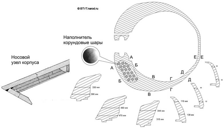
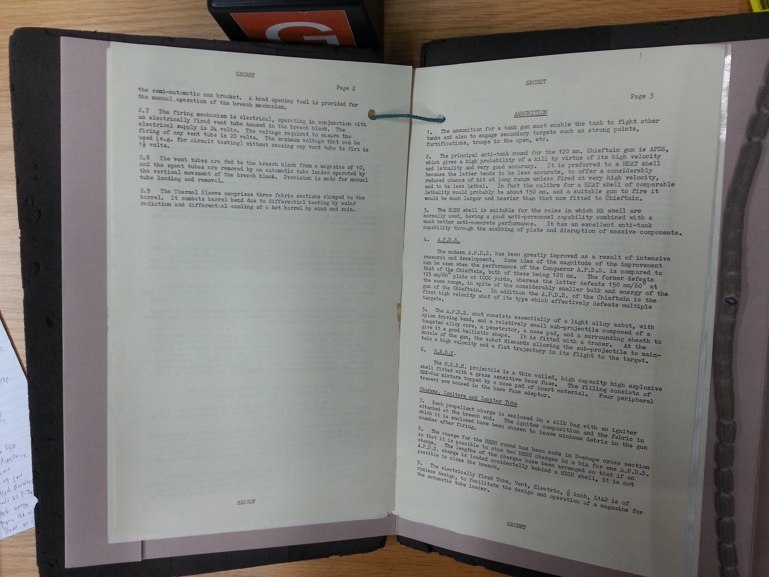
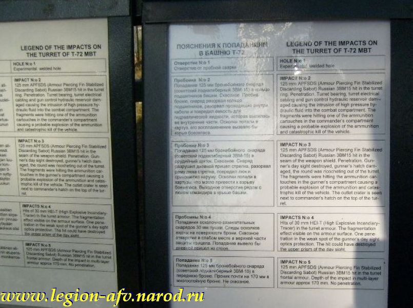
The exhaust outlet for a V-84 type engine is identical in appearance to that of the V-46.

Like previous variants, the T-72B had a nominal top speed of 60 km/h on asphalt roads and an average speed of 35 to 40 km/h on dirt roads.
V-92 (V-92S2F)
 The V-92S2F turbocharged engine boasts an
impressive power density combined with higher standards of reliability and fuel economy. Due to the use of a relatively compact turbocharger instead of the N-46 supercharger, the total length of the engine decreased marginally compared to the V-46 and V-84 series, but the weight of the engine increased marginally to 1,100 kg. The main feature of the engine is that it produces a rated power of 1,130 hp at 2,000 RPM. The warrantied service life of the V-92S2F is unknown, but the warranty service life of the less powerful V-92S2 from which it was derived is 650 engine hours.
The V-92S2F turbocharged engine boasts an
impressive power density combined with higher standards of reliability and fuel economy. Due to the use of a relatively compact turbocharger instead of the N-46 supercharger, the total length of the engine decreased marginally compared to the V-46 and V-84 series, but the weight of the engine increased marginally to 1,100 kg. The main feature of the engine is that it produces a rated power of 1,130 hp at 2,000 RPM. The warrantied service life of the V-92S2F is unknown, but the warranty service life of the less powerful V-92S2 from which it was derived is 650 engine hours.
To drive the turbocharger, new exhaust manifolds were implemented. After passing through the turbine, the exhaust gasses are routed through a duct sitting between the rocker covers. Due to the changes in the exhaust, T-72 tanks equipped with V-46 or V-84 engines require minor modifications to fit the V-92S2F.
The maximum torque output is 4,521 Nm which is a huge improvement over the V-84 engine and nominally exceeds the GTD-1250 gas turbine engine of late production T-80U tanks. It is close to the MB 873 Ka-501. The increased torque output and torque backup greatly improves driving characteristics
across rough terrain and aids in steering, as the torque backup is used to overcome the increased resistance during a turn to ensure that the vehicle does not lose speed compared to straight-line driving. The fuel
efficiency has been substantially improved to just 158 g/hph, fully compensating for the greatly increased power output compared to previous engines, yielding a net increase in driving range without an increase in the fuel capacity of the tank.
The cylinders and pistons were updated and are more robust compared to previous engines to cope with the added power. The T-72B3 UBKh has the V-92S2F installed along with a new transmission and new dual-pin tracks with improved traction on broken terrain. The new transmission was presumably needed because the original transmission had insufficient safety margins for an engine with the power of the V-92S2F, and the gearing ratios also had to be different to allow a higher top speed to be achieved with the new engine. The specific power of the V-92S2F engine is 950 hp/cu.m.
The desired combination of a flat torque curve at the low end, behind the point of peak torque, followed by a downward curve with a large gradient, is naturally provided by electric motors, but in the case of turbocharged engines, can be provided by a smaller and lighter turbocharger which is able to supply its rated boost at the low end of the torque curve.
For the V-92S2F, the torque at the rated power is 3,967 Nm. From this, it can be calculated that the engine flexibility coefficient (torque backup) is 1.14 (14%). This is only a small improvement over the V-84 and V-46, and still does not reach the same level as the MB 873 Ka-501.
Variants of the T-72 outfitted with the V-92S2F can be identified by the heavily modified exhaust unit, now much narrower but taller, and with different cooling fins. A new exhaust unit was needed because of the new narrower exhaust duct that combined the exhaust flow from the turbocharger. It appears that two variations of this exhaust unit exist. The T-72B3 UBKh uses a different exhaust than other tanks using the same engine.


With the cooling fins and muffler removed, the exhaust duct itself is just a simple metal duct.


The use of the V-92S2F on the T-72B3M and T-72B3 UBKh coupled with the new transmission boosts its top speed to a blistering 84 km/h on paved roads and allows it to cruise cross-country at a speed of up to 60 km/h on dirt roads. This elevates the tank's mobility to the level of the T-80BV in terms of speed, and gives it something close to parity when moving cross country thanks to the high torque backup.
ENGINE REMOVAL
To prepare the engine for removal, it is necessary to remove the engine deck by unbolting it and then lifting it off the tank using a crane. From there, the air cleaner unit is removed, then the engine is disconnected from the cooling, lubrication and fuel systems. The engine is then disengaged from the intermediate power transfer gearbox ("Гитара") of the transmission. Following this, the engine is detached from its floor mount which requires the engine compartment firewall to be opened to access the front side of the mount. The engine can then be removed using the same light crane.

According to the book "Основной боевой танк России. Откровенный разговор о проблемах танкостроения" (Main Battle Tanks of Russia. Frank Discussions on the Problems of Tank Building) authored by E.B Vavilonskiy et al., the T-90S, which can be considered a surrogate of any T-72 due to the near-identical design of its powertrain, required a total of 8.5 hours to replace its engine (removal and reinstallment to running condition) during a 2006 demonstration in Saudi Arabia. A well designed quick-replace powerpack is far quicker to replace, although they invariably require special resources such as a crane with a high load capacity, and in practice, an ARV like the Bergepanzer 2 is needed to carry out the task. The engine of the T-90S required 3.5 hours to 4.0 hours to remove and requires nothing more than a workhorse truck equipped with a light crane. The TRM-A-70 or TRM-80 mobile workshop based on the ZIL-131 truck was widely used in this role, since it had a boom crane with a capacity of 1.5 tons. ARVs like the BREM-1 are practically never needed to carry out powertrain field repairs, and are instead used much more often for tank recovery in danger zones, which is the primary role of ARVs.
The average time needed to replace all units installed in the engine compartment is unclear, but it has sometimes been quoted as 3 days. For comparison, the M60A1 needed just 4 hours to have its powerpack replaced. Compared to the Leopard 1 and Leopard 2, the time needed to replace the engine and transmission of a T-72 is is exceptionally long as these two German tanks require only around 35 minutes or less. Well-trained maintenance teams can even replace the powerpack of a Leopard 2 in less than 20 minutes in ideal conditions. The caveat to this is that this restricts all powerpack repairs to be done exclusively by an ARV, as there is no way to access the powerpack components without removing it from the tank, and the only crane with the required load capacity is found on ARVs. It also means that the failure of minor powertrain accessories cannot be solved in the field by the crew, but must involve an ARV and the atention of the maintenance unit personnel. This is the most common form of breakdown, as opposed to a critical engine malfunction or the malfunction of some other major powertrain component, which cannot be repaired rapidly in the field without needing to dispatch a repair team from the maintenance unit. Overall, in practice, the speed advantage of tanks with quickly replaceable powerpacks exists, but is a nuanced compromise.
The V-92S2F turbocharged engine boasts an
impressive power density combined with higher standards of reliability and fuel economy. Due to the use of a relatively compact turbocharger instead of the N-46 supercharger, the total length of the engine decreased marginally compared to the V-46 and V-84 series, but the weight of the engine increased marginally to 1,100 kg. The main feature of the engine is that it produces a rated power of 1,130 hp at 2,000 RPM. The warrantied service life of the V-92S2F is unknown, but the warranty service life of the less powerful V-92S2 from which it was derived is 650 engine hours.To drive the turbocharger, new exhaust manifolds were implemented. After passing through the turbine, the exhaust gasses are routed through a duct sitting between the rocker covers. Due to the changes in the exhaust, T-72 tanks equipped with V-46 or V-84 engines require minor modifications to fit the V-92S2F.
The maximum torque output is 4,521 Nm which is a huge improvement over the V-84 engine and nominally exceeds the GTD-1250 gas turbine engine of late production T-80U tanks. It is close to the MB 873 Ka-501. The increased torque output and torque backup greatly improves driving characteristics
across rough terrain and aids in steering, as the torque backup is used to overcome the increased resistance during a turn to ensure that the vehicle does not lose speed compared to straight-line driving. The fuel
efficiency has been substantially improved to just 158 g/hph, fully compensating for the greatly increased power output compared to previous engines, yielding a net increase in driving range without an increase in the fuel capacity of the tank.
The cylinders and pistons were updated and are more robust compared to previous engines to cope with the added power. The T-72B3 UBKh has the V-92S2F installed along with a new transmission and new dual-pin tracks with improved traction on broken terrain. The new transmission was presumably needed because the original transmission had insufficient safety margins for an engine with the power of the V-92S2F, and the gearing ratios also had to be different to allow a higher top speed to be achieved with the new engine. The specific power of the V-92S2F engine is 950 hp/cu.m.
The desired combination of a flat torque curve at the low end, behind the point of peak torque, followed by a downward curve with a large gradient, is naturally provided by electric motors, but in the case of turbocharged engines, can be provided by a smaller and lighter turbocharger which is able to supply its rated boost at the low end of the torque curve.
For the V-92S2F, the torque at the rated power is 3,967 Nm. From this, it can be calculated that the engine flexibility coefficient (torque backup) is 1.14 (14%). This is only a small improvement over the V-84 and V-46, and still does not reach the same level as the MB 873 Ka-501.
Variants of the T-72 outfitted with the V-92S2F can be identified by the heavily modified exhaust unit, now much narrower but taller, and with different cooling fins. A new exhaust unit was needed because of the new narrower exhaust duct that combined the exhaust flow from the turbocharger. It appears that two variations of this exhaust unit exist. The T-72B3 UBKh uses a different exhaust than other tanks using the same engine.


With the cooling fins and muffler removed, the exhaust duct itself is just a simple metal duct.


The use of the V-92S2F on the T-72B3M and T-72B3 UBKh coupled with the new transmission boosts its top speed to a blistering 84 km/h on paved roads and allows it to cruise cross-country at a speed of up to 60 km/h on dirt roads. This elevates the tank's mobility to the level of the T-80BV in terms of speed, and gives it something close to parity when moving cross country thanks to the high torque backup.
ENGINE REMOVAL
To prepare the engine for removal, it is necessary to remove the engine deck by unbolting it and then lifting it off the tank using a crane. From there, the air cleaner unit is removed, then the engine is disconnected from the cooling, lubrication and fuel systems. The engine is then disengaged from the intermediate power transfer gearbox ("Гитара") of the transmission. Following this, the engine is detached from its floor mount which requires the engine compartment firewall to be opened to access the front side of the mount. The engine can then be removed using the same light crane.

According to the book "Основной боевой танк России. Откровенный разговор о проблемах танкостроения" (Main Battle Tanks of Russia. Frank Discussions on the Problems of Tank Building) authored by E.B Vavilonskiy et al., the T-90S, which can be considered a surrogate of any T-72 due to the near-identical design of its powertrain, required a total of 8.5 hours to replace its engine (removal and reinstallment to running condition) during a 2006 demonstration in Saudi Arabia. A well designed quick-replace powerpack is far quicker to replace, although they invariably require special resources such as a crane with a high load capacity, and in practice, an ARV like the Bergepanzer 2 is needed to carry out the task. The engine of the T-90S required 3.5 hours to 4.0 hours to remove and requires nothing more than a workhorse truck equipped with a light crane. The TRM-A-70 or TRM-80 mobile workshop based on the ZIL-131 truck was widely used in this role, since it had a boom crane with a capacity of 1.5 tons. ARVs like the BREM-1 are practically never needed to carry out powertrain field repairs, and are instead used much more often for tank recovery in danger zones, which is the primary role of ARVs.
The average time needed to replace all units installed in the engine compartment is unclear, but it has sometimes been quoted as 3 days. For comparison, the M60A1 needed just 4 hours to have its powerpack replaced. Compared to the Leopard 1 and Leopard 2, the time needed to replace the engine and transmission of a T-72 is is exceptionally long as these two German tanks require only around 35 minutes or less. Well-trained maintenance teams can even replace the powerpack of a Leopard 2 in less than 20 minutes in ideal conditions. The caveat to this is that this restricts all powerpack repairs to be done exclusively by an ARV, as there is no way to access the powerpack components without removing it from the tank, and the only crane with the required load capacity is found on ARVs. It also means that the failure of minor powertrain accessories cannot be solved in the field by the crew, but must involve an ARV and the atention of the maintenance unit personnel. This is the most common form of breakdown, as opposed to a critical engine malfunction or the malfunction of some other major powertrain component, which cannot be repaired rapidly in the field without needing to dispatch a repair team from the maintenance unit. Overall, in practice, the speed advantage of tanks with quickly replaceable powerpacks exists, but is a nuanced compromise.
COOLING SYSTEM

The cooling system is a closed-circuit, liquid cooling system with forced circulation of the coolant. It has a capacity of 90 liters. The cooling system, depicted in the drawing above, is comprised of a cooling fan, a coolant reservoir, an expansion tank, a water radiator and the radiator water pump. The engine preheater is linked to the cooling circuit. The pump is mounted on the engine itself. The cooling system operates within a moderate temperature range, with a normal (reecommended) coolant temperature of 70-100°C when running on diesel, naphta and kerosene, or 80-100°C when running on gasoline.. The maximum permissible operating temperature is 115°C. When antifreeze is added for cold weather operations, the normal coolant temperature range is 70-90°C when running on diesel, naphta and kerosene, or 80-90°C when running on gasoline. With antifreeze, the maximum operating temperature is 95°C, but driving with a coolant temperature of 105°C is permitted for short periods. The minimum coolant temperature in all cases is 65°C.
Coolant temperatures are sensed by either a critical temperature sensor with a response threshold of 112-118°C, which is used when the tank is operating in conditions of +5°C and above, or another critical temperature sensor with a response threshold of 104-109°C, to be used at temperatures lower than +5°C. The sensors are connected to warning lamps on the PV-82 control panel, located in the driver's station. However, it is important to note that the cooling system is not automatically regulated, and the PV-82 control panel is not capable of initiating an automatic engine shutdown if the critical temperatures are exceeded. Corrective actions must be carried out with the personal intervention of the driver.
The coolant capacity of 90 liters is only a small increase over the 77-liter capacity of the T-62 cooling system and the 80-liter capacity of the T-55 cooling system, both of which coped with the lighter thermal load of the less powerful V-55 engine. Though the slightly larger capacity is beneficial to the extent that it constitutes additional thermal mass to contain more heat energy and thus regulate the rise in temperature, the cooling system of the T-72 was not a direct copy of the existing designs, instead featuring a number of design changes. The much larger amount of waste heat produced by the engine was handled by the higher efficiency of the cooling fan, a redesigned radiator inlet with no bypass vent to supply air to the engine, and the larger surface area of the radiator packs, made possible by the wider hull of the T-72 compared to preceding medium tanks.
Water is pumped around the engine and pumped up to the dual radiator packs where it is cooled. Inside the dual-pass radiator packs, water flows in winding aluminium tubes with cooling fins and heat is removed by air sucked in by an engine-driven centrifugal fan at the rear of the engine compartment. Internal turbulators increase the efficiency of heat transfer by inducing turbulence in the flowing water. At ambient temperatures of +5°C and above, the coolant is water with a three-component anticorrosion additive. Although pure water has a higher heat transfer rate and performs better as a heat transfer fluid, pure water poses the threat of serious long-term corrosion for aluminium engines, and on top of this, the vast majority of accessible water sources contain minerals which can lead to scale formation in the cooling pipework, so the use of an anticorrosion additive or antifreeze is mandatory. Between -35°C to +5°C, grade 40 antifreeze is added to the coolant. At temperatures below -35°C, grade 65 antifreeze is used.
Engine oil is also cooled with two similar single-pass radiator packs installed above the water radiators. The waste heat extracted from the radiator by the air is pulled into the radiator fan and ejected out of the radiator fan outlet at the rear of the hull in an upward direction. Because the radiator pack is located directly beneath the intake grilles, the inlet air temperature for the radiator is exactly equal to the ambient air temperature. Heating of the inlet air, which reduces the heat transfer efficiency, does not occur. Within the airflow path of the cooling system, shown below, the only potential cause for increased inlet temperature is the recirculation of the hot air exiting upwards through the air outlet. When the tank is driven forwards, the formation of a turbulent wake behind the turret, directly over the engine deck, has the potential to circulate the heated air from the cooling fan outlet back towards the radiator inlet. This was mainly addressed by the sloped design of the hull rear and the slanted positioning of the cooling fan, which allows it to blow the waste air to the rear at a 30-degree angle, the same angle as the slope of the rear armour plate. This is in contrast to the T-54/55 and T-62, which had vertically mounted fans that relied on curved outlet vanes to direct the outflow of hot air slightly rearward, though the air stream was still predominantly in an upward direction due to the shape of the duct.

The rotational speed of the fan is determined by the gearing system in the intermediate power transfer gearbox connecting the fan drive to the engine. As engine speed increases, the rotational speed of the fan increases proportionately. The gearbox for the cooling fan can be adjusted only by moving a selector on the intermediate gearbox manually, after lifting open the radiators. The fan drive has three positions: neutral, low and high. The gear ratios for the fan provided by the intermediate power transfer gearbox are 0.647 (high gear) and 0.773 (low gear). For the most part, the choice of the fan speed is tied to the region and season. The fan is set to the "low" mode as the standard setting for most situations, but the driver can switch to the "high" mode if the ambient temperature is higher than 25°C or if the temperature of the coolant and engine oil is observed to be above the critical temperature during operation. For example, during summer, a driver could set the fan to run on "high" and leave it for the entire season, unless he notices that the coolant temperature is excessively low during routine driving. The fan drive must not be left on neutral if the tank is driven. According to Russian patent No. 2199017, the power consumption of the cooling fan consumption is 29 kW (38.9 hp) in the "low" mode and 50 kW (67 hp) in the "high" mode. In the "low" mode, the power consumption of the fan is 4.9% of the gross engine power. In the "high" mode, it is 8.6%. Due to the fact that the fan speed is tied to engine speed, these figures represent the maximum power consumption.
In order to prevent the fan speed from changing abruptly with an abrupt change in engine speed, which could cause damage to the fan, the fan drive is connected to the intermediate power transfer gearbox via a clutch, which transmits a torque of 18-50 kgf (176-490 N). A sudden change in engine speed would cause the clutch disc to slip until the fan speed has equalized with the engine speed, thus ensuring that the light aluminium structure of the fan does not deform under the torque overload.
Aside from the mechanical fan drive, the intensity of the airflow is also regulated by the position of the fan outlet vanes, which is mechanically controlled by the driver via a selector with a pushrod mechanism. The driver can select between six positions, from fully open, where the vanes are completely parallel to the outlet duct, to fully closed.

However, the lack of an automatic coolant temperature regulation system limits the efficiency of the cooling system and limits the potential lifespan of the engine in practice. Beginning with the V-92S2F engine, which can be found in the latest versions of the T-72B3 tank, a built-in detuning mechanism is installed. It automatically limits the power output when the engine temperature becomes excessive. This limits the potential for damage from engine overheating if the driver fails to take corrective actions when warned by the temperature sensors.
Due to the short path between the radiator pack and the cooling fan, aided by the slanted positioning of the cooling fan, the heating of the other units in the engine compartment by the hot air from the radiator is minimalized, while the open airflow within the compartment promotes the cooling of the transmission and especially the brakes, which are located inside the side gearboxes.
The oil radiator is shown in the drawing below on the left, and the water radiator is shown on the right. Both radiators are coupled together to form the radiator pack.


This cooling system was previously used in the same configuration on the T-54 and T-62 and was proven to be sound by over two decades of use, experimentation and refinement by the time the T-72 entered service. One drawback is that dust particles kicked up into the air from driving at high speed may be sucked up by the high velocity air stream from the cooling fan, creating a distinctive "rooster tail" dust cloud behind the tank. The radiator pack, opened for access to the engine compartment, is shown in the two photos below.


Reports indicate that this system may be somewhat limited in extreme hot weather and only sufficient for European summers. The cooling system is designed for maximum cooling efficiency at an ambient temperature of up to 25°C, as higher temperatures increase the load on the system, meaning that the cooling fan requires a larger share of engine power. The normal operating range is defined as 5-25°C, within which the cooling fan is set to the "slow" mode unless the coolant and oil temperature reach the critical threshold when driving. At an ambient temperature of 25°C, the engine is expected to work with no loss in power, but it will begin to experience marginal reductions in performance at higher temperatures. Overheating becomes a major issue in ambient temperatures of up to 50° C, which is sometimes recorded at the Thar desert in India. At temperatures of 45° C and above, the engine will experience a steep reduction in power (up to 33% loss). At such temperatures, the tank must be stopped every 25 kilometers to allow the engine to cool to prevent excessive fatigue.
According to the report "Пути Снижения Затрат Мощности В Системах Танкового Дизеля" ("Ways to Reduce The Power Costs in Tank Diesel Systems") by S.P Baranov and V.T Nikitin, the power consumption of the cooling system of the T-72 is 7.7% when the ambient temperature is higher than the typical operating range of 4°C to 30°C. However, when the system is running within the operating temperature range, the power consumption is only 4.9% which is less than the ejection-type cooling system of the T-64A. This is consistent with the known power consumption of the cooling fan. Even when operating above optimal temperatures, the cooling system of the T-72 is more efficient than the fan-type cooling systems of foreign tanks like the M60A1, Leopard 1 and Leopard 2 which consume 14.4%, 14.7% and 14.5% of engine power respectively.
In total, the net engine power of the V-46 is 11.5% lower than the gross engine power after adding up the costs of the ambient heating of the inducted air. the air cleaning system, and the cooling system. Aside from that, it is stated in the book "Основной боевой танк России: Откровенный разговор о проблемах танкостроения" (Russian main battle tank: A frank conversation about the problems of tank building) that the net engine power of the V-84 is about 11% lower than its gross power (840 hp). In cold weather, the net engine power can be higher due to the higher density of cold air but it could also be somewhat less, as the air intake heater may be used when running the engine at temperatures from 0 to -20°C. The rarefaction of the air reduces the oxygen density in the air delivered to the combustion chamber, and the power of the engine worsens as a result, but the combustion efficiency of the engine is maintained. If fuel efficiency is less of a concern, intake heating can be ignored.
Apparently, the V-92 engine series and its accompanying modifications have partially solved the overheating issue at very high ambient temperatures. Specific details are not known to the author, but it could only either be an increase in the power of the centrifugal fan, or a simple modification of the water flow channels in the radiator, as Indian T-90S tanks apparently have.
The photos below show the radiator covers opened and closed, exposing the protective louvers within.

The cooling system is a closed-circuit, liquid cooling system with forced circulation of the coolant. It has a capacity of 90 liters. The cooling system, depicted in the drawing above, is comprised of a cooling fan, a coolant reservoir, an expansion tank, a water radiator and the radiator water pump. The engine preheater is linked to the cooling circuit. The pump is mounted on the engine itself. The cooling system operates within a moderate temperature range, with a normal (reecommended) coolant temperature of 70-100°C when running on diesel, naphta and kerosene, or 80-100°C when running on gasoline.. The maximum permissible operating temperature is 115°C. When antifreeze is added for cold weather operations, the normal coolant temperature range is 70-90°C when running on diesel, naphta and kerosene, or 80-90°C when running on gasoline. With antifreeze, the maximum operating temperature is 95°C, but driving with a coolant temperature of 105°C is permitted for short periods. The minimum coolant temperature in all cases is 65°C.
Coolant temperatures are sensed by either a critical temperature sensor with a response threshold of 112-118°C, which is used when the tank is operating in conditions of +5°C and above, or another critical temperature sensor with a response threshold of 104-109°C, to be used at temperatures lower than +5°C. The sensors are connected to warning lamps on the PV-82 control panel, located in the driver's station. However, it is important to note that the cooling system is not automatically regulated, and the PV-82 control panel is not capable of initiating an automatic engine shutdown if the critical temperatures are exceeded. Corrective actions must be carried out with the personal intervention of the driver.
The coolant capacity of 90 liters is only a small increase over the 77-liter capacity of the T-62 cooling system and the 80-liter capacity of the T-55 cooling system, both of which coped with the lighter thermal load of the less powerful V-55 engine. Though the slightly larger capacity is beneficial to the extent that it constitutes additional thermal mass to contain more heat energy and thus regulate the rise in temperature, the cooling system of the T-72 was not a direct copy of the existing designs, instead featuring a number of design changes. The much larger amount of waste heat produced by the engine was handled by the higher efficiency of the cooling fan, a redesigned radiator inlet with no bypass vent to supply air to the engine, and the larger surface area of the radiator packs, made possible by the wider hull of the T-72 compared to preceding medium tanks.
Water is pumped around the engine and pumped up to the dual radiator packs where it is cooled. Inside the dual-pass radiator packs, water flows in winding aluminium tubes with cooling fins and heat is removed by air sucked in by an engine-driven centrifugal fan at the rear of the engine compartment. Internal turbulators increase the efficiency of heat transfer by inducing turbulence in the flowing water. At ambient temperatures of +5°C and above, the coolant is water with a three-component anticorrosion additive. Although pure water has a higher heat transfer rate and performs better as a heat transfer fluid, pure water poses the threat of serious long-term corrosion for aluminium engines, and on top of this, the vast majority of accessible water sources contain minerals which can lead to scale formation in the cooling pipework, so the use of an anticorrosion additive or antifreeze is mandatory. Between -35°C to +5°C, grade 40 antifreeze is added to the coolant. At temperatures below -35°C, grade 65 antifreeze is used.
Engine oil is also cooled with two similar single-pass radiator packs installed above the water radiators. The waste heat extracted from the radiator by the air is pulled into the radiator fan and ejected out of the radiator fan outlet at the rear of the hull in an upward direction. Because the radiator pack is located directly beneath the intake grilles, the inlet air temperature for the radiator is exactly equal to the ambient air temperature. Heating of the inlet air, which reduces the heat transfer efficiency, does not occur. Within the airflow path of the cooling system, shown below, the only potential cause for increased inlet temperature is the recirculation of the hot air exiting upwards through the air outlet. When the tank is driven forwards, the formation of a turbulent wake behind the turret, directly over the engine deck, has the potential to circulate the heated air from the cooling fan outlet back towards the radiator inlet. This was mainly addressed by the sloped design of the hull rear and the slanted positioning of the cooling fan, which allows it to blow the waste air to the rear at a 30-degree angle, the same angle as the slope of the rear armour plate. This is in contrast to the T-54/55 and T-62, which had vertically mounted fans that relied on curved outlet vanes to direct the outflow of hot air slightly rearward, though the air stream was still predominantly in an upward direction due to the shape of the duct.
The rotational speed of the fan is determined by the gearing system in the intermediate power transfer gearbox connecting the fan drive to the engine. As engine speed increases, the rotational speed of the fan increases proportionately. The gearbox for the cooling fan can be adjusted only by moving a selector on the intermediate gearbox manually, after lifting open the radiators. The fan drive has three positions: neutral, low and high. The gear ratios for the fan provided by the intermediate power transfer gearbox are 0.647 (high gear) and 0.773 (low gear). For the most part, the choice of the fan speed is tied to the region and season. The fan is set to the "low" mode as the standard setting for most situations, but the driver can switch to the "high" mode if the ambient temperature is higher than 25°C or if the temperature of the coolant and engine oil is observed to be above the critical temperature during operation. For example, during summer, a driver could set the fan to run on "high" and leave it for the entire season, unless he notices that the coolant temperature is excessively low during routine driving. The fan drive must not be left on neutral if the tank is driven. According to Russian patent No. 2199017, the power consumption of the cooling fan consumption is 29 kW (38.9 hp) in the "low" mode and 50 kW (67 hp) in the "high" mode. In the "low" mode, the power consumption of the fan is 4.9% of the gross engine power. In the "high" mode, it is 8.6%. Due to the fact that the fan speed is tied to engine speed, these figures represent the maximum power consumption.
In order to prevent the fan speed from changing abruptly with an abrupt change in engine speed, which could cause damage to the fan, the fan drive is connected to the intermediate power transfer gearbox via a clutch, which transmits a torque of 18-50 kgf (176-490 N). A sudden change in engine speed would cause the clutch disc to slip until the fan speed has equalized with the engine speed, thus ensuring that the light aluminium structure of the fan does not deform under the torque overload.
Aside from the mechanical fan drive, the intensity of the airflow is also regulated by the position of the fan outlet vanes, which is mechanically controlled by the driver via a selector with a pushrod mechanism. The driver can select between six positions, from fully open, where the vanes are completely parallel to the outlet duct, to fully closed.

However, the lack of an automatic coolant temperature regulation system limits the efficiency of the cooling system and limits the potential lifespan of the engine in practice. Beginning with the V-92S2F engine, which can be found in the latest versions of the T-72B3 tank, a built-in detuning mechanism is installed. It automatically limits the power output when the engine temperature becomes excessive. This limits the potential for damage from engine overheating if the driver fails to take corrective actions when warned by the temperature sensors.
Due to the short path between the radiator pack and the cooling fan, aided by the slanted positioning of the cooling fan, the heating of the other units in the engine compartment by the hot air from the radiator is minimalized, while the open airflow within the compartment promotes the cooling of the transmission and especially the brakes, which are located inside the side gearboxes.
The oil radiator is shown in the drawing below on the left, and the water radiator is shown on the right. Both radiators are coupled together to form the radiator pack.


This cooling system was previously used in the same configuration on the T-54 and T-62 and was proven to be sound by over two decades of use, experimentation and refinement by the time the T-72 entered service. One drawback is that dust particles kicked up into the air from driving at high speed may be sucked up by the high velocity air stream from the cooling fan, creating a distinctive "rooster tail" dust cloud behind the tank. The radiator pack, opened for access to the engine compartment, is shown in the two photos below.


Reports indicate that this system may be somewhat limited in extreme hot weather and only sufficient for European summers. The cooling system is designed for maximum cooling efficiency at an ambient temperature of up to 25°C, as higher temperatures increase the load on the system, meaning that the cooling fan requires a larger share of engine power. The normal operating range is defined as 5-25°C, within which the cooling fan is set to the "slow" mode unless the coolant and oil temperature reach the critical threshold when driving. At an ambient temperature of 25°C, the engine is expected to work with no loss in power, but it will begin to experience marginal reductions in performance at higher temperatures. Overheating becomes a major issue in ambient temperatures of up to 50° C, which is sometimes recorded at the Thar desert in India. At temperatures of 45° C and above, the engine will experience a steep reduction in power (up to 33% loss). At such temperatures, the tank must be stopped every 25 kilometers to allow the engine to cool to prevent excessive fatigue.
According to the report "Пути Снижения Затрат Мощности В Системах Танкового Дизеля" ("Ways to Reduce The Power Costs in Tank Diesel Systems") by S.P Baranov and V.T Nikitin, the power consumption of the cooling system of the T-72 is 7.7% when the ambient temperature is higher than the typical operating range of 4°C to 30°C. However, when the system is running within the operating temperature range, the power consumption is only 4.9% which is less than the ejection-type cooling system of the T-64A. This is consistent with the known power consumption of the cooling fan. Even when operating above optimal temperatures, the cooling system of the T-72 is more efficient than the fan-type cooling systems of foreign tanks like the M60A1, Leopard 1 and Leopard 2 which consume 14.4%, 14.7% and 14.5% of engine power respectively.
According to the report "Пути Снижения Затрат Мощности В Системах Танкового Дизеля" ("Ways to Reduce The Power Costs in Tank Diesel Systems") by S.P Baranov and V.T Nikitin, the power consumption of the cooling system of the T-72 is 7.7% when the ambient temperature is higher than the typical operating range of 4°C to 30°C. However, when the system is running within the operating temperature range, the power consumption is only 4.9% which is less than the ejection-type cooling system of the T-64A. This is consistent with the known power consumption of the cooling fan. Even when operating above optimal temperatures, the cooling system of the T-72 is more efficient than the fan-type cooling systems of foreign tanks like the M60A1, Leopard 1 and Leopard 2 which consume 14.4%, 14.7% and 14.5% of engine power respectively.
In total, the net engine power of the V-46 is 11.5% lower than the gross engine power after adding up the costs of the ambient heating of the inducted air. the air cleaning system, and the cooling system. Aside from that, it is stated in the book "Основной боевой танк России: Откровенный разговор о проблемах танкостроения" (Russian main battle tank: A frank conversation about the problems of tank building) that the net engine power of the V-84 is about 11% lower than its gross power (840 hp). In cold weather, the net engine power can be higher due to the higher density of cold air but it could also be somewhat less, as the air intake heater may be used when running the engine at temperatures from 0 to -20°C. The rarefaction of the air reduces the oxygen density in the air delivered to the combustion chamber, and the power of the engine worsens as a result, but the combustion efficiency of the engine is maintained. If fuel efficiency is less of a concern, intake heating can be ignored.
Apparently, the V-92 engine series and its accompanying modifications have partially solved the overheating issue at very high ambient temperatures. Specific details are not known to the author, but it could only either be an increase in the power of the centrifugal fan, or a simple modification of the water flow channels in the radiator, as Indian T-90S tanks apparently have.
The photos below show the radiator covers opened and closed, exposing the protective louvers within.


The photo below shows the engine compartment with cooling pack and engine access panel removed.
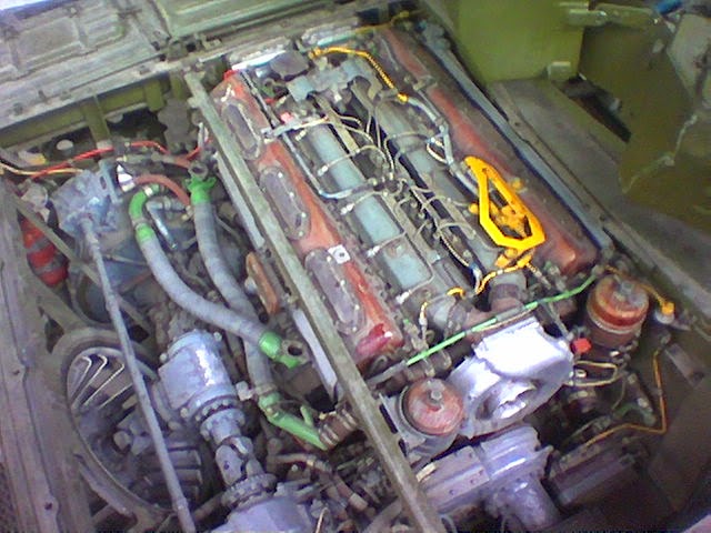
Note the crossbar to hinge both of the aforementioned accessories. Also note the centrifugal fan at the bottom left corner. It is a riveted aluminium fan with a diameter of 655mm and a width of 205mm, with twenty evenly spaced vanes. It is powered by a driveshaft connected to the gearbox so that it increases or decreases its power in accordance with the engine's mechanical output, thus adjusting for the engine's heat output as well. It is strong enough to throw water out of the engine compartment like a blowhole even while the engine is idling. The use of a mechanical power shaft to transmit power, unlike fan belts as used in some other tanks, eliminates the issue of fan belts snapping under the high stress of driving such a fan.


The use of a centrifugal cooling fan is one of the many conservative design features of the T-72, and in fact, the entire cooling system is fundamentally the same as the design used in the T-54. However, that does not mean that it was no longer viable by the 70's, as the design could still meet the cooling requirements of the V-46 engine in most weather conditions due to design refinements while remaining relatively compact, easy to maintain, and reasonably protected, although there are still a few drawbacks.
By placing the radiator on the engine deck and exposing a large surface area, it becomes more vulnerable to napalm attacks or molotov cocktails, as the cooling fan creates a suction force that can suck in burning gels and liquids through the radiator louvers. This is only marginally compensated by the presence of optional watertight covers. Keeping these watertight covers shut and configuring the tank to draw air through the fighting compartment prevents the ingress of burning liquids at the cost of accelerating the overheating of the engine. The cooling fan itself is well protected, since it is too small to be hit by aerial weapons and it can eject any burning liquid thrown inside it.
By contrast, the cooling system of the Leopard 1 may offer better protection against incendiary attack as only the cooling fan is exposed on the engine deck whereas the radiators are not, but the radiators are on the sides of the hull, making them more vulnerable to heavy machine gun fire and artillery shell splinters. The cooling fan itself is barely protected from ballistic attack, but does not need to be, since there is no coolant to leak and it may still function with minor damage.
In the event of damage from an air attack, maintaining or replacing the radiator is quite simple, since the entire unit can be hinged open. The radiator can be disconnected from the coolant pump quite easily, as the two components are only connected by inflow and outflow hoses.

The louvers that protect the radiator and cooling fan outlet can be shut or opened by turning a lever from the driver's station. Closing these louvers provide additional protection from aerial attack and napalm or makeshift weapons such as Molotov Cocktails.


The photo above shows the engine access panel and armoured cover hinged open. The radiator pack cover panel is stowed on top of the engine access panel when not in use. It may help increase the level of protection by acting as rudimentary spaced armour, although it is not particularly thick.

TRANSMISSION

The T-72 transmission consists of dual planetary gearboxes with integrated final drives, a type of transmission that is sometimes referred to as a geared dual transmission system, but more generically known as a transmission with side gearboxes, or BKPs. The two gearboxes are connected by a driveshaft which transmits power from the engine via the intermediate power transfer gearbox ("Гитара"), marked (5) in the drawing above. The transmission does not have a main clutch. This type of transmission was originally developed for the Object 430 by the Malyshev design bureau in Kharkov. The use of BKPs in the T-72 was for the unification of transmissions with the T-64, not only on the industrial level but also in terms of supply and institutional familiarity. A mechanic trained on T-64s would have been able to service the BKPs on a T-72, and the BKPs in T-72s were interchangeable with those in a T-64, simplifying logistics. Direct interchangeability was possible even though the 5TD series engines used in the T-64 ran at a rated speed of 2,800 RPM whereas the V-46 engine in the T-72 ran at a rated speed of 2,000 RPM, because the intermediate power transfer gearbox in the T-72 geared down the output speed by a factor of 0.706, raising the input speed at the BKPs to 2,832 RPM - equal to the rated speed of the 5TDF. The chosen ratio of 0.706 is slightly higher than the 0.7 gear ratio of the intermediate power transfer gearbox of the T-54, T-55 and T-62.
This type of transmission is extremely compact, extremely durable, extremely reliable, and has a very high mechanical efficiency due to its kinematic simplicity. Alone, the left gearbox weighs 710 kg, the right gearbox weighs 700 kg, and the intermediate power transfer gearbox located between the engine and the gearboxes weighs 320 kg. The intermediate power transfer gearbox is shown below. The mechanism acts as a step-up gear between the engine and the BKPs, with a ratio of 0.706. It also provides a power takeoff for the AK-150SV air compressor, SG-10-1S starter-generator and the cooling fan. The gear ratio to the fluid coupling of the starter-generator is 0.693. The gear ratio to the air compressor is 0.934.

The service life of the intermediate power transfer gearbox was 11,100 km, while the side gearboxes and the final drives had a service life of 10,800 km. Service life is defined as the 90% exhaustion of the total life of the unit. The long service life of these units ensured that failures were rare and tank availability rates could be kept consistently high.
The weight of the transmission including the intermediate power transfer gearbox for the radiator fan, pumps, and the ST-10-1S starter-generator is 1,635 kg. The total weight of the transmission assembly with all accessories, including the hydraulic control system and the lubrication system is 1,870 kg. The image below shows the hydraulic control system and the lubrication system, excluding the oil radiator. The hydraulic servo units on top of the gearboxes are used to actuate the clutches.

The total volume occupied by the transmission assembly is 0.43 cubic meters and the volume occupied by each individual gearbox is 0.09 cubic meters. The side gearboxes only occupy approximately the same space as the epicyclic steering units in a T-54 and the gearbox connecting the two steering units in a T-54 are absent in a T-54, so the difference in the occupied volume is tremendous. It is several times less than double or triple differential transmissions used in foreign tanks while offering all of the same features except neutral steering. When installed inside the engine compartment, each BKP is seated in their proper position by a drum-shaped steel case, which also provides mechanical protection. Once removed from their mounts, the BKPs can be readily disassembled.
According to technical reports from Sverdlovsk and Nizhny Tagil published in 1973-1974, the manufacture of the transmission of the T-72 requires 721 man-hours.
The gearboxes are each comprised of four planetary gear sets connected to two clutches and four braking clutches, or brakes. Each side gearbox has a range of 8 gears, 7 forward and 1 in reverse. The recommended engine speed range for shifting gears is 1,600-1,900 RPM. The gears are engaged by selectively applying a pair of clutches or brakes on sets of planetary gears, which produces the desired gearing ratio. In the gearbox, the clutches are wet multi-plate friction clutches that join two rotating assemblies together. The brakes are wet multi-plate friction disc brakes that stop a rotating assembly against the casing of the gearbox, which may be done to stop the ring gear of a planetary gear set to change its gear ratio. Fundamentally, the clutch and brake are essentially the same, only their purposes differ. Both use cermet discs on steel rotors (clutches) or stators (brakes). The plates are oil-cooled by a forced lubrication system, which lubricates and removes the heat generated by friction in both the multi-plate clutches and multi-disc brakes. The clutches and brakes are engaged hydraulically, with a hydraulic system that is pressurized via an engine power takeoff from the intermediate power transfer gearbox ("Гитара"). The gearshift mechanism is a rotary hydraulic valve key which changes the flow pathway of the hydraulic network. When a certain gear is selected, hydraulic pressure is routed to the power piston on the two corresponding clutches or brakes, engaging them and producing the desired gear ratio via the planetary gear sets. The hydraulic pressure on the other power pistons is zero.
In 1st and reverse, the clutches and brakes are engaged at a pressure of 16.5-1.80 kgf/sq.cm. In the normal driving gears, which are the 2nd to 7th gears, the clutches and brakes are engaged at a pressure of 10-11.5 kgf/sq.cm. To prevent the clutch from slipping, stronger thrust is provided by the hydraulic clutch pack pistons, as, with a given coefficient of friction, the torque capacity of a friction clutch increases with the normal force pressing the clutch discs together. In ordinary cars with a dry clutch, the normal force is provided by the springs of the pressure plate, so the torque capacity is fixed. In the BKPs, this force is supplied by the hydraulic system with variable pressure, allowing variable torque capacities.

The effectiveness of such clutches and brakes is proportional to their diameter; in this case, just over 600mm. Larger discs are needed for multi-plate disc brakes and clutches for heavy vehicles and other high-torque industrial applications due to the higher braking torque afforded by large-diameter discs (due to the increased distance from the axle to the disc) and better heat dissipation.
The clutch pedal in the driver's station is used to de-clutch both the gearboxes by de-clutching whatever clutches and brakes are currently engaged as the selected gear, and after the driver selects a new gear, releasing the clutch pedal will engage the clutches and brakes corresponding to the selected gear. The clutch mechanism is a hydraulic relay switch, functioning as a pressure release for the entire gearbox. Once the clutch pedal is fully depressed, hydraulic pressure in all clutches and brakes in the gearbox drop to zero, thus disconnecting the gearbox the from the power input shaft. Because the system is a relay for a powered hydraulic drive, the effort needed on the clutch pedal is minimal. The adjustable return spring of the clutch pedal control rod provides most of the resistance felt by the driver.

The following table shows the various combinations of clutches and brakes used to actuate the side gearboxes. The clutches are identified as (Ф) and brakes are identified as (Т). For instance, the 1st gear is engaged by activating clutch No. 3 and brake No. 4. The 3rd gear is engaged by clutch No. 3 and brake No. 6. Not shown is the combination of brake No. 4 and brake No. 5, which engages the brake in the gearbox and brakes the track. Only brake No. 4 and No.5 have both a hydraulic power piston and a mechanical drive, allowing control by the gear shift, clutch pedal and steering levers, which are hydraulic, as well as the brake pedal mechanism, which is fully mechanical. All other clutches and brakes have only a hydraulic drive and are controlled by the gear shift, clutch pedal and steering levers exclusively.

The planetary gears engaged by the aforementioned clutches and brakes are shown below. Note that this table does not differentiate between the clutches and brakes, labelling all of them interchangeable as clutches. Also note that the 6th gear is incorrectly labeled as using only planetary gear IV. It should be II and IV. Moreover, the table does not mention that the planetary gear engaged in neutral is the IV gear.

Normally, the tank is started on the 2nd gear unless the ground is particularly soft, in which case the tank starts on the 1st gear. Thanks to the large amount of torque available from the engine, the tank readily accelerates from a standstill in 2nd gear, as long as the tank is not on a steep slope or the ground is hard enough that it does not offer high resistance. Acceleration from a standstill is done like in any automobile with a manual transmission; according to the manual, bringing the tank into motion is done by releasing the clutch pedal and depressing the accelerator pedal simultaneously. As the engine idles at 800-900 RPM, its speed rises above 1,000 RPM very quickly and it should reach its operating speed of 1,300 RPM by the time the clutch pedal is fully released.
According to the book "Основной боевой танк России. Откровенный разговор о проблемах танкостроения" (Main Battle Tanks of Russia. Frank Discussions on the Problems of Tank Building) authored by E.B Vavilonskiy et al., the powertrain components in the T-72 and T-90 family of tanks was laid out with the idea of providing the maximum possibility of replacing most of the defective components in the field to expedite repairs in the field without the participation of special tools or resources, which may be unavailable for a variety of reasons.
Based on repair manuals for the T-72M and T-72B, it can also be concluded that the replacement and repair of components was designed to be achievable with minimal manpower in the repair team. Out of 149 replacement and repair operations, 81 can be done by 2 men and 66 can be done by a single man. Only a single operation requires 3 men, and only the replacement of the engine requires 4 men. Considering that the tank crew consists of 3 men, it can be seen that the operations on multiple components can be done in parallel on each tank, or individual operations can be done by a larger workforce very quickly. For labour-intensive procedures such as engine replacement, the crew assists the repair team assigned by the repair and maintenance battalion.

The side gearboxes are coupled to the final drive as a single module. To replace these modules from a T-72, it is necessary to break track, remove the drive sprocket, open the radiator pack on its hinges to disconnect the oil lines, then unbolt the final drive housing from the side hull plate, and finally pull out the entire module with a crane. In field conditions, the crane would normally be provided by a TRM-A-70 or TRM-A-80 mobile workshop based on the ZIL-131 truck with a crane capacity of 1.5 tons. Conceptually, this process is similar to the transmission replacement process of an M4 Sherman, but much less laborious and much less demanding on the load capacity of the crane. The simplicity of the replacement process makes it expedient to swap out broken down transmissions in field conditions. For comparison, the work of removing and reinstalling the transmission unit on a Sherman required no less than 64 man-hours. The same work on the left and right BKP units require just 21 and 16 man-hours respectively, so it is generally quite quick and convenient to carry out parts replacement even at lower levels of organization.


STEERING SYSTEM
As with the geared steering system of the T-54 and T-62 transmissions, the BKPs of the T-72 allow the tank to be steered by slowing down one track, or by de-clutching one track, or by de-clutching one track and braking it. Clutch-brake steering is used only in 1st gear and reverse. Steering in higher gears is regenerative, as power is delivered to both tracks. As with rectilinear motion, the transmission has one degree of freedom when the tank is turning. Unlike the T-54, T-55 and T-62 transmission which only offers a single turning radius of 8.91 meters regardless of the selected gear (with the additional option of a clutch-brake turn with a radius of 2.64 meters), the T-72 transmission provides multiple turn radii, with each gear providing its own unique turn radius. This is because the transmission is a classical twin-transmission system, whereby each track is provided with its own gearbox, mechanically identical to the other. By shifting one gearbox to the next lower gear in sequence, the inner track is slowed down and a turn is obtained. By giving every two gears in sequence a different relative ratio, one unique turn radius is obtained in each gear. This enabled smoother and more precise steering without the reduced efficiency of other steering mechanisms.
For example, if the tank enters a left turn when traveling in 2nd gear, the left BKP is shifted to 1st gear while the right BKP remains in 2nd gear. The ratio of the 2nd gear to 1st gear (4.4 ÷ 8.173) is 0.538, and so the left track will turn at 0.538 times the speed of the right track, which is a large difference. A tight turn is thereby obtained. If the tank enters a left turn when traveling in 3rd gear, the left BKP is shifted to 2nd gear while the right BKP remains in 3rd gear. The ratio of the 3rd gear to 2nd gear (3.485 ÷ 4.4) is 0.792, and so the left track will turn at 0.792 times the speed of the right track. The speed difference is much smaller, and the turn radius is expanded accordingly.
A simple formula can be used to calculate the turn radii at each gear. The turn radius formula is as follows, where the gear ratio difference is obtained by subtracting the current gear setting of the BKPs in rectilinear motion from the gear ratio of the next lower gear.

| Gear | Turn Radius (meters) |
| 1 | 2.79 |
| 2 | 6.04 |
| 3 | 13.42 |
| 4 | 13.93 |
| 5 | 10.23 |
| 6 | 10.1 |
| 7 | 8.76 |
| R | 2.79 |
It can be seen that the turn radius begins to tighten in 5th gear, which is counter-productive. It is desirable for a tracked vehicle to have progressively larger turn radii at higher speeds to allow effective steering without skidding and to facilitate gentler steering corrections, and in this regard, an unusual drawback of the BKP steering system is that the turn radius becomes progressively smaller beginning with the 5th gear owing to the decrease of the relative ratio between the 5th and 4th gears, 6th and 5th gears, and the 7th and 6th gears. This was due to the fact that the choice of gear ratios of the BKP transmission was primarily subordinated to ensuring high tractive properties in rectilinear motion, high acceleration by keeping the engine in its power band, and a high top speed, compromising the effectiveness of the turn radii at high speeds. Because of this, precise steering can become more difficult at higher speeds (30 km/h and above) and in conditions of low traction efficiency as an average driver cannot accurately predict how much the tank will skid when turning, and the tank tends to lose more speed with each turn.
However, the negative impact of this aspect of the BKP is greatly lessed by the fact that, in all gear settings, the turn radius can be increased by only pulling the steering lever part way between the full forward and full back positions. When the steering lever is initially pulled back from its full forward position, the hydraulic control system instantaneously drops the pressure in the clutches and brakes for the selected gear, disengaging it, while smoothly raising the pressure on the clutches for the lower gear, allowing it to slip. This is done by a modulating rotary spool valve which can vary the clutch pressure by controlling the inflow and outflow rates of the hydraulic fluid, thus controlling the rate of pressure rise from anywhere between a net zero change in pressure to a quick jump to 10-11.5 kgf/sq.cm, whereupon the clutches fully engage. In this way, the turn radius is controlled by hydraulic pressure on the clutch pistons, which in turn is controlled by the angle of the steering lever. The speed of the inner track during the turn will therefore not correspond to the speed in gear, but rather to an intermediate speed. At the same time this is occurring in the BKP of the inner track, the pressure in the clutches and brakes of the overtaking track is raised from 10-11.5 kgf/sq.cm to 16.5-18.0 kgf/sq.cm in a stepwise manner. This is because the regenerative action of the steering system recirculates power to the overtaking track in the form of torque (since the track speed is fixed), so the BKP of the overtaking track has its clutches and brakes engaged at a pressure equivalent to the 1st or reverse gears to prevent the clutches and brakes from slipping due to torque overload.
When steering by clutch slip, the turn radius will therefore be variable between a minimum, which will be fixed turn radius of the selected gear gear settings, and no turn, which is rectilinear motion. Thus, the turn radius will range from the tabular values to infinity. For example, if the tank is moving in 5th gear and the driver turns right by jerking the right steering lever, the tank will enter a turn with a radius of 10.23 meters with minimal delay. If, however, the driver chooses any arbitrary lever position between full forward and full back, the tank can turn in a radius ranging from 10.23 meters to infinity. Small and precise steering adjustments are done this way, and it is also less tiring as the levers are not repeatedly pulled back all the way. In high gears (5th to 7th), the low controllability of the tank when using the full minimum-radius turn makes it much more effective to steer within the intermediate range.
The downside to utilizing the precision steering feature is that it has a relatively low mechanical efficiency; when a clutch slips, the full sum of the torque arriving at the clutches is still delivered through the clutches even while they are slipping, but the full sum of power is not, due to the mismatch in speed between the engine and the drive sprocket (power is the product of torque and rotationanl speed). Some of the power is lost by conversion into heat. While inefficient, it is permissible to slip the clutches in the BKPs thanks to the fact that they are wet clutches with forced lubrication, and use cermet friction pads with high thermal stability. The film of transmission oil on each disc surface of the multi-disc clutch pack greatly limits mechanical wear and thermal wear is limited by the rejection of waste heat into the flowing transmission oil. Moreover, although it is characterized by much higher power loss compared to steering with engaged clutches, steering by clutch slippage is still regenerative. As the left and right tracks are connected via the transmission drive shaft, the power not transmitted to the inner track flows to the outer track.
It is worth noting that the use of slipping wet clutches with hydraulic pressure to obtain a variable turn radius is a technical solution that the BKP shares with the Allison Cross Drive (CD) series. Cross drive transmissions feature a double differential steering mechanism and lack a hydrostatic steering drive, but the turn radii was considered to range from pivot (neutral steer) to infinity, despite the fixed gearing ratio between the main drive and the steering drive. Instead, the cross drive transmission design simply uses the slipping of the left and right steering clutches when steering left and right respectively. As with the BKP design, this is controlled by having the pressure pistons of the clutches be controlled by a hydraulic modulating valve, but rather than steering levers, the driver's steering device is a wobble stick, steering wheel or T-bar, depending on the tank model.
The tank slows down during a turn because the inner track is slowed down but the outer track is not sped up. If a higher speed is desired, the driver has to increase fuel flow to the engine with the accelerator pedal to overcome the speed reduction and maintain the same vehicle speed as before entering the turn. The engine speed itself does not fall, because the governor can increase the fuel supply to compensate for the increase in the engine load if the rolling resistance exceeds the torque output of the engine. During a turn, the engine runs at the speed set by the operator via the accelerator pedal and the speed is maintained by the governor regardless of the load on the engine. It will continue to do so as long as the load applied has not reached or exceeded the engine's torque curve, but once a torque overload occurs occurs, the governor ceases to maintain engine speed. Instead, engine flexibility (adaptability), which is dependent on the flatness of the torque curve, plays the primary role in minimizing the fall in engine speed. The curvier (peakier) the torque curve, the less the engine speed needs to fall until equilibrium between torque and load is reached. When turning the tank at high speeds on unpaved surfaces, the overload caused by the turning resistance from both the inertia of the tank and the terrain will be handled by these characteristics.
Nevertheless, because of the fundamental limitations of this type of steering system as compared to a differential steering system, exacerbated by the tightening of the turn radii at gears above 4th gear, a tank with BKPs suffers a speed decrease of up to 50% during a turn relative to rectilinear motion. For comparison, the M60A1 with the CD-850-6 transmission experiences a speed decrease of only around 15%.
Clutch-brake steering is the only method of steering on the 1st and reverse gears. The clutch-brake turn produces a turn radius equal to the width of the tank between the centerline of the tracks, expressed as "B" in the table below, taken from the Polish textbook "Budowa pojazdów gąsienicowych" (Construction of Tracked Vehicles). The width of the tank between the centerline of the tracks is 2.79 meters, and so the turn radius is 2.79 meters. In the 1st and reverse gears, the turn radius is 1B, while in the 2nd gear it is 2.16B, and so on.


Theoretically, the turning rate of the tank when turning in 1st gear is around 41.75 degrees per second, allowing the tank to complete a full pivot turn in around 8.6 seconds if the engine ran at 2,000 RPM for the entire duration of the turn. In reverse, the tank would turn at around 23.8 degrees per second under the same circumstances, requiring 15 seconds for a full pivot turn. In practice, due to the need to accelerate from a standstill and then slow down to a stop at the end of the turn, a full pivot turn requires somewhat more time to complete, with real demonstrations showing that around 10 seconds is required. Broadly speaking, this turn rate is on par with tanks capable of neutral steering with on-the-spot turning, but it is nominally slower to tanks like the T-54, T-55 and T-62 which permitted a pivot turn in any gear setting, allowing the driven track to achieve a much higher angular speed, though the highest possible gear setting was still constrained by terrain resistance limitations.
On a final note - when the clutch pedal is depressed or when the gearshift is set to neutral, the steering system does not function. Another important nuance of the steering system is that if a T-72 is being towed, the steering system will not work, because the engine is off and there is no hydraulic pressure in the BKPs.
SPEED AND ACCELERATION
According to the manuals for the T-72A and T-72B and the book "Main Battle Tank" (Основные Боевые Танки) published by Arsenal Press in 1993, the tank speeds (at 2,000 RPM) and gear ratios are presented in the table below. Note that the gearbox has a geometric progression from gears 2 to 4, which are the most commonly used gears, allowing the optimum engine speed range to be maintained within these gears. Gears 5 to 7 have no mathematical progression, serving only to increase the speed of the tank on roads, with the 7th gear present only for the sake of providing the desired top speed. The 1st gear is a high reduction gear for circumstances that demand high tractive force.
The final drive gear ratio is 5.454. The overall gear ratio can be found by multiplying the 0.706 gear ratio of the intermediate power transfer gearbox with the selected transmission gear ratio and the final drive gear ratio. Knowing these gear ratios, the tank speeds in each gear can be calculated quite easily. Taking the 1st gear as an example, it can be calculated that the torque is multiplied 31.47 times and the angular speed is reduced by 31.47 times. If the engine is running at 2,000 RPM, the sprocket speed will be 63.55 RPM, and given the drive sprocket radius of 0.313 meters, the speed can be calculated to be 7.32 km/h.
| Gears | Tank speeds (km/h) | Gear ratios | Overall gear ratios |
| 1 2 3 4 5 6 7 R |
7.32
13.59 17.16
21.47 29.51
40.81 60
4.18 |
8.173 4.400 3.485 2.787 2.027 1.467 1.0 14.3 |
31.47 16.94 13.42 10.73 7.80 5.64 3.85 55.06 |
Knowing the overall gear ratio at 7th gear, it can be calculated that the technical maximum speed of the T-72 is 68.8 km/h, achieved by running the engine at its maximum speed of 2,300 RPM. The engine cannot run faster than 2,300 RPM due to its governor. However, reaching the technical maximum speed requires a paved road, because the engine power drops off beyond its rated speed due to a steep decline in torque, making it difficult for the tank to overcome the resistance of rough terrain. The results of the tests of Object 172 tanks in the Turkestan Military District in 1968 showed that the average speed of the tanks on a paved road was 43.4 to 48.7 km/h, and the maximum speed recorded was 65 km/h, presumably achieved by driving down a straight stretch of highway.
With this in mind, it is important to note that a T-72B3 reached a speed of 77 km/h on the straight dirt road track during the 2018 Tank Biathlon held in Alabino proving grounds outside of Moscow, and during the 2020 Tank Biathlon, a T-72B3 reached 84 km/h, also on the dirt road track. Because it is known that the V-92S2F engine does not run at a higher speed than prior engines, it is evident that a new transmission with new gear ratios was installed to these participating tanks, and possibly serial T-72B3 tanks as well. This would not be particularly surprising given that the greatly increased torque from the new engine would most likely require gearboxes rated for a higher torque.
By examining the speeds permitted by these gear ratios, it can be seen that during the design of the BKP transmission, there are more gears than required to merely keep the engine running within its powerband of 1,300-2,000 RPM. Rather, the ratios were calculated so that when upshifting at an engine speed of 1,900-2,000 RPM from the 2nd gear to a higher gear, up to the 4th gear, the engine speed will not fall below 1,600 RPM. This means that when accelerating while the tank is already in motion (not from a standstill) for short dashes from cover to cover in off-road conditions, the engine will always be in the upper end of its powerband, and it will always be delivering close to its peak power. From the 5th gear to the 7th gear, the spacing between the gears is expanded so that the when upshifting at an engine speed of 1,900-2,000 RPM, the engine speed will fall to 1,300-1,400 RPM. This was done to make use of a wider engine speed range to gain a higher top speed, at a small expense to acceleration, as it is important to note that when shifting from 6th to 7th gear, the engine will still be within its powerband, though only by a small margin. This is in stark contrast to the 4HP 250 transmission of the Leopard 1, which has a 4-speed gearbox. Because the Leopard 1 was designed to achieve a top speed of 62 km/h at its rated engine speed of 2,200 RPM (65 km/h when the engine is at its max speed), it is immediately apparent that the gearbox had to be designed to make use of a much wider engine speed range than the 7-speed BKPs. In fact, due to the wide spacing between the gears in the 4HP 250, the engine speed will fall from 2,200 RPM to 1,200 RPM after shifting from 1st to 2nd (a wide gear spacing exists due to the high gearing ratio of the 1st gear, like all other tanks), and then to 1,400 RPM after shifting from 2nd to 3rd, and 3rd to 4th. Because the peak torque of the MB 838 CaM-500 engine is developed at 1,550 RPM, it is evident that the gear ratios were calculated so that upshifting would push the engine well below its power band for the sake of a higher top speed.
Ideally, the driver should upshift close to 2,300 RPM in order to maximize the acceleration period in each gear, especially in the first few gears, but this may not be desirable during routine maneuvers for wear and tear reasons. This can be seen in torque-speed chart below, which shows the torque curves of the V-46 in each gear of the transmission at an engine speed of 1,000-2,000 RPM against vehicle speed. The chart also shows the close and uniform spacing between the 2nd, 3rd and 4th gears, where acceleration is highest. The spacing between the 5th, 6th and 7th gears is also quite uniform but noticeably wider, which is responsible for the high top speed, achieved with at the expense of acceleration performance.

As the chart shows, the crossover point between each gear in sequence from the 2nd to the 7th does not occur at 2,000 RPM, but rather at a speed that, when extrapolated, lies around 2,300 RPM. The chart also shows that there is a steep drop off when shifting from the 1st to the 2nd gear even when the curve is extrapolated out to 2,300 RPM, so a smooth transition is not possible at all. Some acceleration potential will naturally be lost during the upshift. This could be solved by reducing the gearing ratio to a much smaller figure so that the overall ratio would only be around 20, but this was accepted as a calculated loss, which is a design compromise shared with the majority of other tank transmissions, as the 1st gear is usually designated as a special low range gear for bearing heavy loads. On the T-72, the 1st gear is primarily meant for low speed maneuvering in restricted terrain, towing heavy loads, turning sharp corners in tight spaces, climbing obstacles, crossing trenches, climbing very steep hills, getting the tank to move if it is stuck, and any other situation where a great deal of torque is needed.
The gear shifting mechanism has an interlocker that is designed to prevent the driver from downshifting in the 7th to 5th gear settings (7th to 6th, 6th to 5th, 5th to 4th) unless the engine speed is below 1,500 RPM. This is accomplished by an electronically controlled actuator on the gear shift lever which mechanically locks the lever against the selector frame until the engine speed is below the minimum threshold. When the lock is active, a red warning light on the left of the driver's TNPO-168V periscope is illuminated to warn the driver. The interlocker was needed because shifting down at an engine speed of above 1,500 RPM in these gears causes the engine to overspeed, exceeding its governed maximum speed of 2,300 RPM. This causes premature wear. Ideally, the driver should downshift at 1,300 RPM or less. Switching off the interlocker is prohibited except in case of emergencies. No interlocker is present when downshifting at the 4th to 1st gears, as the close spacing in the gears makes it very hard to overspeed the engine. In this regard, the 7-speed transmission has a positive effect on the ease of driving, as the speed margins for upshifting and even downshifting (up to the 5th gear) are very flexible. For instance, the driver could safely downshift from the 4th gear to the 3rd gear at a speed of as high as 1,800 RPM without overspeeding the engine, or upshift from the 3rd gear to the 4th gear at a speed of only 1,550-1,600 RPM and still end up at 1,300 RPM in 4th gear - just within the power band.
Another merit of the 7-speed transmission is that it provides the driver with enough gearing options to run the engine at its most efficient speed of ~1,600 RPM (where its specific fuel consumption is lowest) when the tank must be driven at a steady speed, such as in convoys.
The unusually slow reverse speed of the T-72 is explained by the immense gearing ratio, enabling a T-72 to extricate itself if it gets stuck in a ditch. It can also be used when towing another tank if success cannot be achieved with the 1st forward gear. No explanation for the slow reverse speed on the T-72 is given in the technical manual, operator's manual or any textbooks, but such a slow speed was not uncommon for tanks of WWII vintage.
The gear shift is the same one used in the T-64 and is shared with that of the T-10 heavy tank. Only sequential upshifting and downshifting is allowed by the gearboxes. Only sequential upshifting and downshifting is permitted, with a mechanical interlock to prevent the driver from skipping gears.


A new electronic control system was reportedly installed for the transmission in the T-72B3 UBKh. Very little information is available on the new system.
The steering levers control the hydraulic servo units, which greatly reduces driver fatigue. The amount of force needed to pull the steering levers is around 16 kgf.

The steering levers have two positions, forward and back. To steer, the driver pulls the right or left steering lever back. This causes the side gearbox on the corresponding side of the hull to downshift instantaneously and thus reduce the track speed, or brake if the transmission is in the 1st gear or reverse gear setting. The speed difference between the two tracks causes the tank to turn around the slower track.
The brake, which is mechanically assisted by a spring, is operated with the brake pedal, or the steering tillers when in the 1st gear, neutral and reverse gears. Slowing down the tank with engine braking is also practical in the T-72 due to its manual transmission, and is the main braking method when moving down a steep descent with the intermittent application of the brake to prevent the engine from overshooting its maximum speed. As in a normal automobile with a manual transmission, engine braking is applied by shifting to a lower gear. This can be done with the gear shift or by pulling both steering levers back and holding them in place until the tank has reached the bottom of the slope. Engine braking also serves as a means of slowing down from high speed on level ground.
The effort needed on the pedal is mechanically reduced by a pair of coil springs and a reduction mechanism with a variable gear ratio, shown in the image below. When depressed, the brake pedal actuates a pushrod which turns an input cam against an output cam in the reduction mechanism, creating a two-stage multiplication of the driver's pushing force on the control rods for the No. 4 and No. 5 brakes in the BKPs, thereby activating the brake. The reduction mechanism provides a more modest driver pedal force multiplication in the first stage, and the second stage provides a much higher multiplication factor, needed to fully lock up the brakes when the brake pedal is fully depressed.
The use of multi-disc brakes for this purpose is particularly appropriate owing to the high braking forces needed to stop a moving tank. To engage the parking brake, the pedal is held in place with a hook and rack mechanism. The brake pedal mechanism is fully mechanical and is not linked to the hydraulic units of the transmission, and is therefore not boosted by the engine power, unlike the braking mechanism which is engaged by the steering lever (in 1st gear and reverse). This makes the brake pedal a redundant system that can function regardless of the condition of the engine or hydraulic systems, which is an important safety feature for bringing the tank to a stop during emergencies, keeping the tank parked when the engine is off, and braking a broken-down tank while being towed with a towing cable. On the other hand, the lack of a powered booster of any kind could make the brake pedal very heavy to depress when the tank is travelling at high speed and a high braking force is needed to stop it. According to a report on the capabilities of a testbed T-64A equipped with a new hydromechanical transmission, the basic T-64A requires a brake pedal force of 50-100 kgf (490-980 N) to depress. Because it weighs more than a T-64A, a T-72 should be more difficult to stop and thus require more effort on the brake pedal.

Another way to activate the brakes is to shift into 1st gear, and then pull both steering levers back simultaneously, activating the brake on both BKPs hydraulically. Because the hydraulic system directly acts upon the multi-disc brake packs, no force is transmitted into the mechanical brake linkages, and all resistance except the force of the return spring is removed from the brake pedal because the brake packs are already compressed. This can be done to quickly control the brakes without stopping the tank while traversing obstacles at low speed. It is the recommended way of bringing the tank to a full stop on a slope. The engine does not stall when both steering levers are used for braking in 1st gear or reverse gear, because the BKPs are automatically de-clutched. Once the tank is fully stopped, the driver steps on the brake and clutch pedals, releases the steering levers, and shifts into neutral.
Beginning on January 1, 1978, a pneumatic braking system was installed to the T-72. The mechanism, and the associated modifications to the pneumatic network of the tank, was also installed in all subsequent models of the T-72 series. It is analogous to the pneumatic brake used in heavy trucks and buses, but it is more powerful and provides no fine control over the braking force, as it is either turned on or off. The work is done by a pneumatic cylinder located in the engine compartment, connected to the brake linkages via the input cam of the reduction mechanism. Air enters the piston chamber via the inlet indicated by the red arrow in the drawing below, and the piston rod (14) is pushed out of the cylinder, turning a lever arm on the casing of the mechanism that turns the input cam. Because the brake pedal linkage is splined into the input cam, the activation of the pneumatic cylinder also causes the brake pedal to be depressed. In this way, the driver receives physical feedback on the magnitude of the braking force by sensing how far the pedal is depressed.

The mechanism was designed to brake the tank without using the brake pedal, and it also moves the brake pedal to a more convenient position for later use, after the tank has slowed down. The driver activates the system while the tank is in motion by pressing and holding the brake button on the end of the left steering lever, shown in the image on the right below. This sends an electric signal to two EK-48 electro-pneumatic valves connected in series, releasing a flow of pressurized air to the pneumatic cylinder, turning the linkage for the brake control rods and thus engaging the brakes. The tank is then fully braked, only without any physical effort from the driver. The recommended pressure in the tank's pneumatic system for using the brake is 6.8 MPa (69 kg/sq.cm or 986.2 psi), which is - quite appropriately - vastly higher than pneumatic brakes for commercial heavy veicles, almost 10 times higher. However, because the bore diameter of the pneumatic cylinder is relatively small compared to truck brakes for the sake of compactness, a high braking force is obtained from a relatively low actuator force by having a longer piston stroke to produce more work, which goes through the input cam (1) to the output cam (9) in the reduction mechanism, shown in the image on the left below, to reduce the linkage displacement and thus amplify the actuator force. Under normal conditions, the pressure in the pneumatic system should be no less than 7.4 MPa to ensure that pneumatic starting of the engine is possible, so the pneumatic brake should always be ready to use, and the presence of the AK-150SV air compressor allows the brake to be used in perpetuity.


Before releasing the braking button, the driver places his foot on the brake pedal, which will be depressed. Once the braking button is released, the air is evacuated from the system by a release valve and control of the pedal is returned to the driver, so he must step on it to ensure the tank continues to remain braked. If there is no force on the pedal, it will return to its original position under its spring. The addition of this pneumatic braking system was presumably done to ensure that the tank could be forcefully braked while travelling at high speed without requiring excessive effort on the driver's part.
The use of wet multi-plate disc brakes was an exceptionally modern feature at the time. The Patton series used dry multi-plate disc brakes, while most other tanks used more familiar automotive braking technologies such as the T-54/55 and T-62 which used band brakes, or the Leopard 1 and Chieftain which used a single-plate dry friction disc brake with twin calipers. All of these offered acceptable performance but were a suboptimal choice for a hot, enclosed engine compartments compared to a multi-plate brake with forced oil cooling. Moreover, the combination of a hydraulic control system with a mechanical control system, supplemented by a pneumatic actuator, made the T-72 braking system completely unique in the automotive world.
When starting a tank from a standstill, the driver can shift to the 2nd or 3rd gear and have both steering levers pulled back, thus setting the BKPs to the 1st or 2nd gear. Then, when the driver releases the clutch pedal and accelerates, he can rapidly shift up a gear by returning both steering levers to the forward position without needing to use the clutch pedal. In effect, this essentially duplicates the function of a semi-automatic transmission for one upshift or downshift, and it can be done at any gear setting. It may be exploited to maximize the acceleration of the tank on hard ground, but it is particularly favourable to do this when setting the tank in motion in 1st gear on a slope and in bad terrain because upshifting with this method is faster, reducing the period in which the tank can decelerate while engine power is no longer delivered to the tracks.
Due to the use of a manual transmission with a high mechanical efficiency, the net power at the drive sprockets of the T-72 is actually slightly higher than the Leopard 1, and the higher low end torque output of the V-46 engine allows the tank to accelerate very quickly. However, the T-72 generally falls short of the Leopard 1 in terms of steering precision, as its 4HP 250 double differential transmission provides two turn radii per gear, giving the tank a total of 8 turn radii as opposed to the 7 radii available on the T-72. The T-72 can only achieve more than one turn radius in each gear by partially downshifting one track, to make minute steering adjustments. The hydrostatic double differential transmission of the Leopard 2 is even more sophisticated as it provides an infinitely variable turning radius.
The T-72 is not capable of neutral steering. When the gearshift is set to neutral, the steering system does not function; pulling the steering levers has no effect. The T-72 can only perform a pivot turn, that is, turn by locking one of the two tracks in place while the other drives the tank around it. This method of steering is mechanically simple, but inferior to turning in place whereby both of the tracks receive power and one of the tracks is run at the desired speed while the other is run in the opposite direction. Besides being slower, pivot steering induces strain on the inactive track and pushes soil between it and the road wheels, creating more tension that may cause the track to be dislocated from the suspension if not alleviated by running the track, either by momentarily making the tank go forward or in reverse. This is not an issue on dirt, sand, snow or paved surfaces, but is a possibility if the tank is turned in thick clay.

Driving the T-72 is a pleasant experience - at least compared to a T-54 - according to people with firsthand experience. A few of the reasons, besides the fully hydraulic control of the steering system, are the low center of gravity of the tank and the uniform weight distribution on the roadwheels, and indeed, the tank was designed so that the weight distribution is most uniform when the turret is facing forwards. By having all these positive features, oscillations are less pronounced and the handling is easier. The tank is also more stable when moving at high speeds, particularly on harsh terrain. Nevertheless, the tiller system is perhaps inherently less ergonomic than a steering bar or wheel in terms of steering effort. The technical advantages of the tiller system over the slightly more complex steering bar system are that tillers are mechanically simple, durable, provide a great deal of leverage to reduce steering effort, and frees up space for the driver's legs.
Though the tiller steering system can be considered one of the more antiquated aspects of the T-72, it's worth noting that many of its rivals like the AMX-30, Chieftain and Challenger used the same system as well.
With a total power loss of 11-11.5% before the power is transmitted to the gear boxes of the transmission, the T-72 retains a larger share of its engine power than the M60A1, Leopard 1 and Leopard 2. Thus, the net engine power of the T-72 Ural and T-72A is 682 hp, and the net engine power of the T-72B is 712 hp. This is slightly more than the 642 hp of the M60A1, 630 hp of the M48A3, and only slightly less than the 710 hp of the Leopard 1 but much less than the 1,260 hp of the Leopard 2. It is closely equivalent to the Challenger 1 which has a net engine power of 871 hp.
However, the modest engine power compared to tanks like the Leopard 2 is somewhat counterbalanced by the lower weight of the T-72, which is lower than both the M60A1 and Leopard 2 for all T-72 variants. Astonishingly, the weight of a combat loaded T-72 Ural (41 tons) is even slightly lower than a combat loaded Leopard 1A1 (41.5). Of course, these power deductions are only for the engine related subsystems. The deductions from the electrical systems of the tank are not yet considered. For example, the ST-10-1S generator on the T-72 generates 10 kW, and this power comes from the engine. The electrical systems of foreign tanks are typically more power-hungry which is often reflected in better performance in certain aspects (quicker turret rotation speed, more powerful infrared spotlights), but also results in slightly lower net power. Transmission losses may also reduce the power available to drive the tracks. A manual transmission with friction side clutches like the type installed in the T-72 has lower parasitic power losses compared to automatic transmissions. The maximum power loss to the transmission in a T-72 at peak engine power is 70 hp, compared to an estimated 200-250 hp in a Leopard 2. The high power losses suffered by the Leopard 2 are due to the low efficiency of hydrostatic double differential transmissions, particularly when steering.
With a power loss of 11.5% to auxiliary systems and another 8.9% (70 hp) to the transmission, the sprocket power of a T-72 is 620 hp. For comparison, the sprocket powers of the Leopard 2, Leopard 1, Challenger 1, M60A1 and Chieftain Mk. 5 at peak engine power are 1,000 hp, 572 hp, 871 hp, 520 hp and 585 hp respectively. As a result, the actual power-to-weight ratios of these five tanks are quite different than what the net engine powers imply. Additional losses to the electric generator are substantially less for the T-72 - its generator has an output of 10 kW, whereas the generator of the M1 Abrams produces 15.6 kW and the generator of the Leopard 2 produces 20 kW. However, for this comparison, they are omitted.
| Tank | Gross engine power-to-weight ratio (hp/ton) | Sprocket power-to-weight ratio (hp/ton) |
| Leopard 2 | 27.20 | 18.13 |
| T-72 Ural | 19.00 | 15.12 |
| Leopard 1 | 20.75 | 14.30 |
| Challenger 1 | 19.35 | 14.05 |
| Chieftain Mk. 5 | 13.64 | 10.63 |
| M60A1 | 15.76 | 10.5 |
During the evolution of the T-72, the sprocket power-to-weight ratio remained at the same approximate level despite the gradual increase in weight of each new model. For instance, the T-72B obr. 1985 and T-72B obr. 1989 both weighed 44.5 tons, but the sprocket P:W ratio actually increased marginally to 15.22 hp/ton due to the 840 hp engine. The much more recent T-72B3 model weighs 45.6 tons and has the V-84M engine with the same output of 840 hp, so the P:W ratio declined to 14.86 hp/ton. On the most recent T-72 model, the T-72B3 UBKh, the gross P:W ratio increased drastically to 24.3 hp/ton, but the exact sprocket P:W ratio is not known because the losses have not been disclosed. Under the reasonable assumption that the same transmission is still used, the sprocket power is around 900 hp. With a combat weight of 46.5 tons, the sprocket P:W ratio of the T-72B3 UBKh is around 19.35 hp/ton.
ACCELERATION
Acceleration data for the T-72 is somewhat difficult to find. According to the report "Propozycja Poprawy Manewrowości Czołgu Twardy" (Proposal to Improve Maneuverability of the "Twardy" Tank) from the University of Technology in Szczecin, the T-72M1 accelerates to 32 km/h in 10.5 seconds on a paved road. Data for the T-72B from empirical data is available in a journal article "Теплоинерционное кратковременное форсирование мощности танкового двигателя и его технические возможности" by B. I. Vasiliev, S. V. Dorogin, et al. The relevant table is presented below. The time taken for a T-72B with a V-84 engine operating under normal power (840 hp) to accelerate to 30 km/h (T1) is 8.5 seconds on concrete, and 12 seconds on a dirt road. Accelerating to its top speed of 60 km/h (T2) takes 27.6 seconds on concrete, and 38 seconds on a dirt road. Note that the use of a concrete track instead of a paved road may degrade acceleration performance due to higher track slippage, particularly since only metal tracks were available for T-72 tanks.
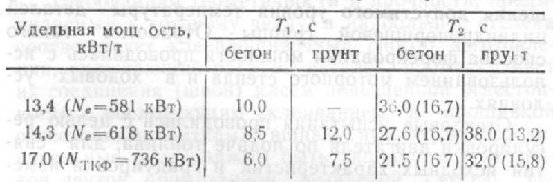
The acceleration figures for the T-72 are supported by original technical documentation on the acceleration of the T-64 with the 5TDF opposed-piston engine (700 hp). The chart below (taken from Andrei Tarasenko) shows the drop in engine performance when jet fuel (grey line, ТС) and low octane gasoline (white line, A-72) is used instead of diesel (black line, ДЛ), but more importantly, the chart shows that a T-64 (Object 432) running under normal conditions on diesel fuel accelerates from 0 to 32 km/h in 10 seconds, although this was because the BKP transmission was optimized to reach 30 km/h. Reaching 32 km/h required an additional gear shift from 5th to 6th, which misrepresents the tank's acceleration performance. The T-72 Ural with the V-46 engine has a marginally higher power-to-weight ratio, better running characteristics, and identical gearboxes, only counterbalanced to some extent by the larger rotating mass in its suspension, so it must have similar acceleration characteristics as the T-64 at the very least, and likely noticeably better.

By cross-referencing data for the T-64 and the T-72B, there is a strong indication that the acceleration of a T-72 Ural to 32 km/h should be between 8.5 and 10.5 seconds, with 4 gear shifts to bring it from 2nd to 6th gear. If the acceleration time is measured to 30 km/h, a T-72 Ural will likely take around 7 seconds. The performance of a T-72 can be expected to outshine that of a T-64A at all speeds, as the T-64A had the same acceleration dynamics as the T-64, but was slower due to its added weight. For the T-64A, acceleration to 40kph is 16-17 seconds
The report "Propozycja Poprawy Manewrowości Czołgu Twardy" also states that a "Leopard 2" accelerates to 32 km/h this in 9.5 seconds and the M1A1 Abrams achieves this in 7 seconds. The acceleration figure for the "Leopard 2" presented in the study is most likely erroneous, as the Leopard 2A0 model is known to be capable of accelerating to 32 km/h in 6 seconds. More contemporary sources repeat that the acceleration of the M1 Abrams to 32 km/h as 6.2 seconds. Paul-Werner Krapke states in "Leopard 2: Sein Werden und seine Leistung" that the Leopard 1 accelerates to 32 km/h in 10 seconds on a paved street. Additionally, according to Soviet tests and data sheets from various U.S sources, the M60A1 with the T97E2 track reaches 32 km/h in 15 seconds and reaches 40 km/h in 25 seconds. It is also stated on page 12 of the May-June 1977 issue of "ARMOR" magazine that the M60A3 reaches 32 km/h in 16 seconds, presumably also with T97E2 tracks. With T142 tracks, which began replacing the T97E2 in 1974, the acceleration to 32 km/h and 40 km/h worsened to 17.5 seconds and 30 seconds respectively. For comparison, the XM-1 reaches 32 km/h in 6.2 seconds.
Interestingly enough, measuring the acceleration to 32 km/h makes for an informative comparison between the T-72 and the Leopard 1. The T-72 may start from 2nd or 3rd gear, and then shift up a few times to reach the 6th gear and hit a speed of 32 km/h. On the other hand, a Leopard 1 has a torque converter that provides enhanced starting authority, which is promptly locked once the tank is in motion, and the driver only has to upshift twice, to the 3rd gear, but due to the wide spacing between the gears in the 4-speed transmission, the engine speed will fall well below the power band after each shift. Delivery of engine power to the tracks is therefore interrupted up to half as many times as in the T-72, but the engine is forced to work back up to its power band from a much lower speed after each gear shift, where it operates at a low efficiency due to the negative influence of turbolag. Evidently, the non-optimal circumstances faced by these two tanks balance each other out, with the outcome being that both tanks share virtually the same acceleration time to 32 km/h, with the T-72 likely beating the Leopard 1 by a small margin.
In terms of acceleration, the T-72 was clearly superior to tanks like the M60A1/M60A3 and was at least on par with the Leopard 1, but was undoubtedly inferior to the new generation of NATO tanks, i.e, the Leopard 2 and M1 Abrams. As a side note, the Polish study also includes figures for the PT-91 "Twardy" which weighs 45.3 tons and has a modern Polish S-12U engine with a power output of 850 hp. The PT-91 reportedly accelerates to 32 km/h in 11.0 seconds, which is congruent with the acceleration figure of the lighter T-72M1 with a less powerful V-46 engine. The acceleration of all four of these modern tanks far outpaces tanks like the T-54 and others of its generation; a basic T-54 requires 18 seconds to reach 32 km/h on a paved road, placing it in the same class as the M48 and M60A1 in this category.
However, it is worth noting that there is a possibility for some doubt to arise regarding these acceleration figures for the T-72 as the acceleration of a generic T-72 model from 0 to 32 km/h is claimed to be 14 seconds in this promotional webpage for the PP1000 powerpack upgrade for the T-72. It is quite likely that the numbers given in the Yugoimport page are for acceleration on a dirt road instead of an asphalt road, or for a tank that weighs substantially more than a basic T-72 model. This may be a T-72M1, as it was likely used as a reference point. This would also match very well with the known acceleration data for a T-72B on a dirt road.
With the available set of data on the acceleration of various tanks on concrete or paved roads, it can be seen that the sprocket power-to-weight ratios offer a more accurate reflection of the comparative acceleration performances of tanks, and indeed, it is a far better point of comparison than the gross power-to-weight ratios. It is worth noting that some small discrepancies in the sprocket P:W ratio and the acceleration time in the table can be explained by the presence of a torque converter, which improves acceleration smoothness from a standstill, but at the expense of additional power losses. In the case of the T-72, despite having a marginally higher sprocket P:W ratio than a Leopard 1 and almost the same amount of suspension rolling resistance, it does not possess a quicker acceleration time to 32 km/h. It can be assumed that this is partly because of the number of upshifts needed, and partly because its steel tracks experience slip on concrete, whereas rubber padded tracks experience negligible slip. Based on the data presented previously, a T-72 Ural is likely to reach 30 km/h in around 7 seconds, while a Leopard 1 would require 7-8 seconds, but this would be achieved solely due to a wider gap in sprocket P:W ratio of 15.12 hp/ton against 14.30 hp/ton.
| Tank | Sprocket P:W ratio (hp/ton) | Acceleration to 32 km/h (s) |
| Leopard 2 | 18.13 | 6.0 |
| Leopard 1 | 14.30 | 10.0 |
| T-72M1 | 14.95 | 10.5 |
| M60A1 | 10.5 | 17.5 |
| T-54 | 10.75 | 18.0 |
| Chieftain Mk. 5 | 10.63 | 19.0 |
SUSPENSION

The T-72 has independent suspension using full-length torsion bars, with each bar running across the full width of the hull. The front two wheel housings are affixed to the hull with reinforced bolts to withstand additional stresses when the tank is driven on uneven ground or into ditches. According to Vasily Chobitok in "Ходовая Часть Танков" (The Running Gear of Tanks), the torsion bars of the T-72 are made from 45KhN2MFASh steel alloy. They are coated with a layer of varnish and then wrapped in a protective insulating tape for scratch protection and to prevent corrosion. Though the composition of the alloy is the same as the 45KhN2MFA alloy used in the torsion bars of the previous generation of medium and heavy tanks, 45KhN2MFASh was processed by electroslag remelting, marked by the "Sh" suffix. The bars are 2,310mm long and 47mm in diameter, and each weighs 31.7 kg.
Both the idler wheel and drive sprocket are cast steel components. The idler wheel weighs 197 kg and the drive sprocket weighs 193 kg. The idler wheel has a diameter of 520mm, and the drive sprocket has a diameter of 611mm as measured along its rim (not the tips of the teeth), which defines the point where its circumference is measured to calculate track speed. There are three support rollers on each side, each having a single tyre on the inner side of the track center guides. As such, they function purely as support rollers, and do not assist in retaining the track. Each roller weighs 31 kg. They have a diameter of 204mm.
The nominal ground clearance of the T-72 Ural and T-72A is 470mm and was increased to 490mm on the T-72B for improved mobility. The ground clearance is measured from the hull belly, and not the driver's "tub" which protrudes below it and is level with the roadwheel swing arm housings. The minimum ground clearance as measured to the "tub" is 406 mm, or 426 mm on the T-72B.
This suspension, inherited from the Object 167, was a departure from the unsupported tracks of the preceding T-54 and T-62 tanks. It consists of six evenly-spaced roadwheels, 750mm in diameter, with three return rollers on each side of the hull. As a rule, return rollers increase the rolling resistance of a suspension, but in this case, the use of a supported track layout provided the roadwheels with much a larger range of dynamic motion, which was presumably too large for the wheels to accommodate unsupported tracks. Like the roadwheels of the preceding T-54, T-55 and T-62 tanks, forged aluminium stampings are used in their construction, helping to save weight and reduce roling resistance. By the time the T-72 entered service, this had become a standard practice among major tank builders, with the U.S first using aluminium tank roadwheels beginning with the M60, and both Germany and France followed suit with the Leopard 1 and AMX-30. Only the Chieftain continued using steel roadwheels (inherited from the Centurion), with aluminium roadwheels appearing only beginning with the Challenger 1.
This suspension, inherited from the Object 167, was a departure from the unsupported tracks of the preceding T-54 and T-62 tanks. It consists of six evenly-spaced roadwheels, 750mm in diameter, with three return rollers on each side of the hull. As a rule, return rollers increase the rolling resistance of a suspension, but in this case, the use of a supported track layout provided the roadwheels with much a larger range of dynamic motion, which was presumably too large for the wheels to accommodate unsupported tracks. Like the roadwheels of the preceding T-54, T-55 and T-62 tanks, forged aluminium stampings are used in their construction, helping to save weight and reduce roling resistance. By the time the T-72 entered service, this had become a standard practice among major tank builders, with the U.S first using aluminium tank roadwheels beginning with the M60, and both Germany and France followed suit with the Leopard 1 and AMX-30. Only the Chieftain continued using steel roadwheels (inherited from the Centurion), with aluminium roadwheels appearing only beginning with the Challenger 1.
The structure of each wheel consists of two stamped aluminium discs bolted together and fastened to a steel hub. Inside the steel hub, a 142220 roller bearing and a 371 ball bearing are fitted. Thick rubberized rims are fitted to the discs, and steel wear plates protect the inner rims of the wheel from the friction of the track center guides. Officially, each wheel is listed as having a weight of 177 kg, presumably representing the complete wheel unit with the hubcap installed. The first wheel on each side of the hull is reinforced with an additional roller bearing.
The T-72 Ural used the 172.50.002sb-A wheel, an 8-spoked design weighing 164.15 kg. Subsequent models with increased weight used the reinforced 172.50.001sb-A wheel with 6 spokes, featuring a different, reinforced roller bearing. The 001sb-A wheel weighs 169.28 kg. On top of that, the swing arm for each roadwheel weighs 87.87 kg. For comparison, the smaller, 660mm-diameter wheels of an M60A1 weighed 125 kg.


The 1st, 2nd and 6th swing arm pairs are reinforced to withstand stronger dynamic loads, and thus weigh 59 kg instead of 55 kg like the 3rd, 4th and 5th swing arm pairs. Together with the swing arm and torsion bar, the complete wheel unit has a nominal weight of 265 kg, similar to the individual wheel weight of a T-54, T-55 and T-62. The large weight of the wheel increases the rotating mass of the suspension, which has a negative influence on the dynamic characteristics of the tank, namely in terms of acceleration and the suspension reaction when steering. Having a larger unsprung mass also makes the tank itself heavier, which is undesirable as well. The main advantage of larger diameter wheels is that rolling resistance is reduced, but due to the heavier powertrain and reduced traction from the RMSh track design compared to the dual-pin RMSh track of the T-64, the advantage is small.
The photos below give a good view of the wheels.

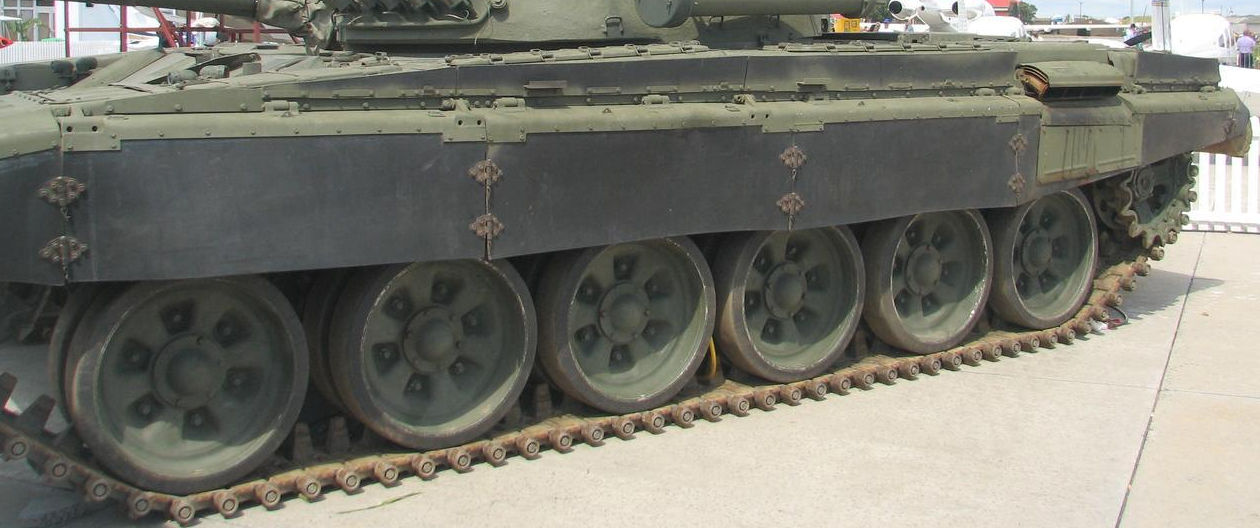
Due to the close similarity in dimensions between the 810mm roadwheels of the T-54 and the 750mm roadwheels of the T-72 and the fact that the RMSh tracks used by the T-72 were designed to work with both types of wheels, it is ostensibly possible to convert a T-72 to use the older type. The main modification would be to add a few more track links to accommodate the larger diameter. The axle socket of the T-54 wheel has the same diameter of 85mm as the axle socket of the T-72 wheel, and in fact, the wheels of the T-72 share the same internal axle sleeve (54.12.022-2А) as T-54 wheels which ensures cross-compatibility. T-54 wheels are sometimes seen on T-72s in repair depots. However, the suspension interchangeability between the T-72 and older medium tanks was not total, because the tank cannot use old OMSh tracks. The drive sprocket does not work with the OMSh track, and there is no pin retention ramp built into the sides of the hull to hammer the track pins back into place as they work themselves out.


The first, second and last roadwheel on both sides are augmented with hydraulic rotary shock absorbers. The front two shock absorbers are highly beneficial as the tank crosses rough terrain, while the rearmost shock absorber is intended to assist recovery when driving through dips and bumps. Simple bump stops are affixed to the sides of the hull for each swing arm to prevent the arm from overextending beyond the deflection limit of the torsion bar and shock absorber. This type of bump stop simply blocks the further motion of the swing arm without damping the shock forces as a hydraulic or volute spring bump stop would. As such, the cross-country ride would tend to be harder at high speeds compared to a suspension system with damping bump stops.

A cross section of the shock absorber is illustrated below. The device is compact and relatively light, each filled shock absorber assembly having a weight of 66.6 kg. It is a vane type shock absorber with the vanes splitting the body into two pairs of opposing chambers, with a regulator valve in each vane opening. Vertical motion of the roadwheel swing arm deflects the lever arm of the shock absorber, transforming linear force into torque which is applied to the vane rotor. The rotary motion of the vanes displaces the hydraulic fluid from the high-pressure chamber to the opposing low-pressure chamber via the vane opening. The restriction of fluid flow through a small opening creates a resistance to motion, converting kinetic energy into thermal energy, thus damping the force applied by the roadwheel. The large amount of heat produced by the interaction is absorbed by the tank hull and removed by the flow of cool air.


This type of shock absorber was previously used on the T54 and T-62 series, but the shock absorbers of the T-72 have a much greater range of travel so that the load is absorbed progressively over a longer distance. This greatly softens the oscillation of the hull, making it a much smoother ride compared to a T-54/55 or T-62. The larger range of travel is depicted in the drawing below by the dotted lines. Drawing taken from the book "Kampfpanzer: Die Entwicklungen der Nachkriegszeit" by Rolf Hilmes.

The ranges of travel are listed in the drawing below. Altogether, the bump travel varies from 254-315mm and the rebound travel varies from 43-116mm for an overall travel range of 358-370mm. This was a large improvement compared to the 224mm of overall travel offered by the T-54/55 or T-62 suspensions, and it was achieved by producing the torsion bars using a new steel alloy alongside the increased length of the torsion bars (2,310mm vs 2,180mm). It was also good compared to all foreign tanks of the 1970's, with the closest counterpart in terms of performance being the Leopard 1. The Leopard 1 had a bump travel of 227-279mm and a rebound travel of 128-156mm, giving a larger overall travel range of 383-407mm. However, the relative importance of bump travel with regard to ride quality at high speeds over bumpy terrain far outweighs that of rebound travel, and because of this, the T-72 suspension is not inferior to that of the Leopard 1.

Compared to the suspensions of the M60A1, AMX-30 and the Chieftain, the difference in performance is very stark. An interesting exception is the Strv 103 as its hydropneumatic suspension offered an exceptionally large overall wheel travel range of 379-543mm, but gave an unusually bumpy ride (likened to that of a camel ride in a British evaluation) as the vehicle was unstable due to its short track base and the fact that it had just four roadwheels on each side. However, the three next-generation NATO tanks all surpassed the T-72 in ride quality. The M1 Abrams and Leopard 2 both offered excellent damping with much larger overall travel ranges of 481mm and 470mm respectively, though it is important to keep in mind that the difference in rebound travel is disproportionately higher than the bump travel. The bump travel of the M1 Abrams and Leopard 2 suspensions is 381mm and 325-331mm respectively. The Challenger 1 had a hydrogas (hydropneumatic) suspension that offered an overall travel range of 450mm with 350mm of bump travel at a nominal temperature of 20°C.
In terms of ease of accessibility such as routine maintenance (such as lubrication, as shown below) or the replacement of damaged wheels, the design of the roadwheels and idler wheels of the T-72 is not different than any other type.


TRACKS
Track tension was adjusted in a manner that is familiar to most tankers; a large wrench (the "tanker bar") is fitted onto the protruding nut of a worm gear in the idler wheel housing, marked in the photo below with a white arrow.

The nut is then twisted to turn the worm gear inside the housing which rotates the idler wheel around its axle, thus shifting it forwards or backwards.

RMSh
In 1964, the RMSh track (613.44.22sb) began replacing the older OMSh track for T-54, T-55 and T-62 tanks. It is a live track. Existing tanks would be converted over to the new track during scheduled maintenance at repair facilities by having their drive sprockets replaced. By the 1970's, the RMSh track was the most common type in the Soviet Army. The design of the RMSh was continuously refined, and in 1972 an improved RMSh track was adopted by the Soviet Army. It had a service life of up to 10,000 km. The T-72 used the improved track from the beginning of its service in the Soviet Army, and the improved track was also issued as the new standard for T-55 and T-62 tanks. This was achieved by using a new and improved steel grade with greater wear resistance and strength. Some structural changes were also made to the design of the track itself. As a result, the mine resistance of the new RMSh track was 1.5 times better than the old OMSh track.
During mine tests in the late 1970's, it was found that the single-pin RMSh track was more resistant to mine blasting compared to the tracks of the T-64 and Object 219 (T-80). It was determined that 1.4 kg of TNT or its equivalent is required to sever the RMSh track on a T-72. This difference was largely meaningless against most anti-tank mines, including most track-breaker mines with a small explosive mass, but against very light, rocket or helicopter-delivered scatterable track breaker mines of the same class as the domestic PTM-1, a resistance limit of 1.4 kg of TNT provided the tank with a margin of safety. In the event that such a mine is encountered, the tank may retain some mobility to withdraw from the minefield under its own power, keeping the crew out of risk.
Each side of the T-72 requires a set of 97 RMSh track links which may be reduced as the track is worn and eventually stretches. The T-72 uses the same number of RMSh track links as the T-62. The track measures 580mm in width and 137mm in pitch. A rubber bushing is fitted between the pin and the pinhole, both of which are hexagonal. The bushings reduce vibrations, reduce wear and tear and also dampen the noise levels compared to all-metal tracks. The track links are made of G13LA Mangalloy (Hadfield steel). It has a hardness of 170-217 BHN. Each track pin has a diameter of 30mm, and the eyelets for the pins have an external diameter of 38mm.


The ground contact length is 4,270mm, as opposed to 4,242mm of the T-64 tracks. A full set of 97 links weighs just over 1,723 kg for one side, and 3,446 kg for a pair of two tracks. These tracks were simpler than the dual-pin tracks of the T-64A and had better traction on rocky and sandy terrain, but had worse traction in mud and other types of terrain and were not as durable. The RMSh tracks compare unfavourably to the T142 tracks of the M60A1. These tracks are also heavier than the T-64A tracks which weighed just 1,450 kg.
 |
| Old drive sprocket |
Rubber track pads were not used during the career of the T-72 in the Soviet Army as such pads were found to increase the track mass by approximately 40% and are ineffective when driving over rough terrain. Of course, that is not to say that they do not come with any benefits. On the contrary, it was experimentally established that rubber track pads increased traction on concrete by 40%, and on dry soil by 7%. When moving on roads, the average speed of a tank column can be increased by 10-15%. However, in practice, metal grousers provide better performance when driving cross-country across a variety of surfaces, including mud, snow, sand and soil.
UMSh
Newer UMSh dual-pin tracks are available, also measuring 580mm in width. UMSh tracks were specially developed for the T-80 as a necessity because of the uniquely high stresses on the suspension from the high torque from its gas turbine engine and also because of the tank's high average speed across rough terrain. As such, these tracks were the smoothest and most durable of the three types used by the Soviet Union's three main battle tanks. Installation of the newer tracks requires modified drive sprockets, so only the newer modifications of the T-72 have this installed, including some late production T-72B variants.
The interior surface of the track pads are rubber-lined so that the rubber rims of the roadwheels roll on a rubber surface rather than a metal one. This prolongs the life of the roadwheels and also helps to reduce the vibrations transmitted to the tank from driving over rough ground. The reduction in vibrations increases the comfort of the crew and improves the accuracy of the weapons while firing on the move, at the expense of slightly increasing the rolling resistance. An entire set of tracks weighs 1,760 kg and the combined weight of a pair of tracks is just under 3,520 kg. There are 80 track links per side.

Because the weight increase is negligible - less than 80 kg - the installation of UMSh tracks did not noticeably increase the weight of the tank. Overall, the effect of replacing the RMSh track with the UMSh track was purely beneficial.
The ground contact length with the UMSh tracks is very slightly longer than on the RMSh tracks - 4,290mm instead of 4,270mm. The photo below (courtesy of Vitaly Kuzmin) shows a T-72B3 with UMSh tracks and rubber track pads installed for driving on paved roads.

There is a simple mud scraper bolted on to the side of the hull in every T-72, just above the drive sprocket. The scraper helps to prevent loss of traction from excess soil on the tracks, especially sticky mud like clay.

The T-72 continued to use the same sheet metal mudguard design until the T-72B variant, when it was replaced by a T-80-style rubber mudguard design. The two mudguard types are interchangeable between all T-72 variants, and indeed, many examples had the new mudguards retrofitted during regular scheduled overhauls. The photo below on the left shows the original sheet metal mudguards on a T-72 Ural and the photo below on the right shows the new mudguard on a modernized T-72 Ural.


The reason for the switch is not entirely clear, but it is very likely that the main impetus was the greater durability of a rubber mudguard. It is likely that unlike sheet metal, the rubber flap of the new design could flex and deform elastically under adverse conditions while still maintaining enough rigidity to perform its primary function as a mudguard. The T-90 and T-90A continue to use the new rubberized mudguards to this day.
The T-72 Ural and T-72A exert 0.83 kg/sq.cm of nominal ground pressure, while the T-72B, being heavier due to its thicker armour and incorporation of ERA, put in 0.898 kg/sq.cm of ground pressure. Compared to its immediate foreign counterparts, the T-72 had little to no advantage in soft terrain, despite being a great deal lighter than all of its adversaries. Against the Chieftain, Leopard 1 and M60A1, the T-72 Ural and T-72A fared slightly better in this respect, but the T-72B was neither better nor worse than its more modern rivals like the Leopard 2, Challenger 1, M60A3 and the M1 Abrams. The weight discrepancy doesn't manifest in this regard, but it becomes much more apparent when we consider the infrastructure of Eastern Europe at the time, especially the bridges - both permanent and temporary ones - which had stricter weight restrictions. Another advantage of the light weight of the T-72 is that it is light enough to be transported on existing rail platforms (the maximum cargo load limit was 55 tons), and also light enough to be compatible with the weight limit of the old MTU-55 bridge layers and TMM truck-based bridge layers, both of which were and still are present in large numbers in the Russian Army Engineers.
When parked or moving on a hard surface, where the weight of the tank is applied over the single track link directly underneath each roadwheel, the mean maximum ground pressure (MMP) is obtained instead of the nominal ground pressure. Given a fixed vehicle weight, the mean maximum ground pressure is governed by the area of a track link and the number of roadwheels over which the weight is divided rather than the entire track contact area, with the number of roadwheels being the dominant factor. By this metric, the T-72 is significantly inferior to its foreign counterparts, as shown in the table below, with a T-72 having an MMP of 430 kPa as compared to the M60A1 (335 kPa), Leopard 1 (344 kPa), and so on. All tanks are combat-loaded in this comparison. This is not very surprising, as the T-72 has one fewer roadwheel pair, and it uses a single-pin track with a short pitch, unlike the longer-pitched double-pin tracks found on all four foreign tanks compared in the table.

Broadly speaking, this is indicative of the difference in the design priorities of these opposing tank designs, as a low mean maximum ground pressure is most relevant for tanks that must drive on paved roads, as a high MMP translates to a high load on rubber track pads, and thus strongly affects the lifespan of track pads, and a high MMP is responsible for more intense damage to roads. Soviet tanks did not use track pads, and did not rely on road networks for long-distance travel, which apparently gave the suspension designers far a much larger allowance in the permissible MMP limit compared to their NATO counterparts.
There are, however, mitigating factors which are not addressed by direct comparisons, which are the wheel diameter and the track surface itself. The latter factor is perhaps the most obvious, as on asphalt or concrete, the surface of a metal track, which is grousered, does not distribute the load onto a surface that is directly equal to the surface area of a single track link, but onto the ends of the grouser protrusions, which naturally translates to a very high mean maximum pressure. For this reason, metal tracks penetrate into asphalt and concrete and cause severe damage. The use of rubber track pads for driving on paved roads also has a similar effect, as the contact patch of the rubber pad(s) on a track link are also invariably smaller than the surface area of the track link itself. Indeed, for tracks that were designed to use rubber track pads for both on-road and off-road driving, the dependence on using the protruding track pad as a grouser can mean that the pad contact patch is only half as large as the track link itself, as exemplified by the American T97E1 and T142 tracks for the M60A1.
The factor of wheel diameter is largely irrelevant when driving on paved roads, but on deforming terrain, the diameter of the roadwheels is responsible for distributing the load more evenly when the track is flexed in following the contours of the terrain. This is shown in the diagram below, from the engineering textbook "Расчет И Конструирование Гусеничных Машин", edited by Professor N. A. Nosov. The extent of track flexion is exaggerated in the drawing to illustrate the effect. Compared to the case of the suspension on terrain, the suspension on hard ground exerts a high mean maximum pressure because the track tension has little effect when the track is laid flat on the ground. On deforming terrain, the track redistributes a significant proportion of the load between the wheels, partly due to the terrain conforming to the circumference of the roadwheels and partly via track tension. Due to this, when compared to the nominal ground pressure (dashed line), the MMP is only somewhat larger.

For a given amount of space between roadwheels, track tension and track pitch, increasing the diameter of the roadwheels can reduce the MMP. With highly tensioned tracks, the tracks deform less and can hold the wheels in compression excessively, which negatively affects off-road mobility. Thus, assuming that track tension is equal between tanks with supported track suspension (unsupported track suspensions generally require slightly less track tension), the other major factor in reducing MMP is the roadwheel diameter. When normalized to a generalized pressure parameter (labeled pressure 'Q' in Table 20 above) which takes into account the flex of the track such that the area through which the load is transmitted to the ground is dependent on the ratio of the diameter of the roadwheel and the pitch of the track, the pressure is much closer to foreign tanks, reaching 183 kPa compared to a pressure of 170-171 kPa for all four foreign tanks. The disadvantage in nominal MPP, which is between 25-38%, translates to a real difference of only 7.6% on terrain when this parameter is considered. This is only a fraction (20-30%) of the difference in nominal MPP. Keeping this in mind, along with the nominal ground pressure, it can be seen that the T-72 may not be significantly inferior to foreign tanks in the most relevant parameters for cross-country travel when using RMSh tracks, depending on the terrain. A T-72B3 with a nominal combat weight of 45.6 tons will have an MMP of 391.7 kPa with its dual-pin tracks, due to the longer track pitch of 164mm.
Thus, it can be seen that there is a great deal of complexity involved in the subject, and that direct comparisons of nominal figures are usually not valid as comparisons of capability. Secondary merits also deserve consideration, as, for instance, the use of tracks with a shorter pitch provides advantages in track noise, vibration, and track life.
Finally, it is worth noting that if the T-72 were trapped in swamps, bogs or in deep snow, it may escape with the help of an unditching log.

By tying the log to track pins on both right and left tracks as illustrated below, the tracks will drag the log along and under them, thus forcing that section of the track to rise above the mud while simultaneously giving the track something more solid to drive over. This allows the tank to get out of the hairiest situations.

The unditching log was demonstrated in Sweden by an ex-GDR T-72M1 in 1991 as part of a series of tests. Colour photo available on the ointres.se website.
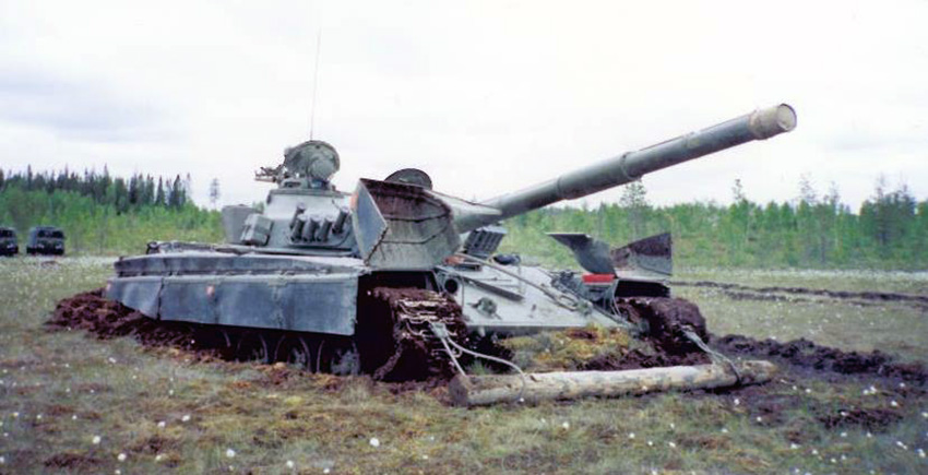

Here is a video (link) demonstrating a tank unditching itself using the log.
WATER OBSTACLES


The T-72 is equipped with the OPVT fording system which includes a snorkel. The system allows the T-72 to cross deep water obstacles in the same manner as the T-64, which also uses the OPVT system. It is possible for the tank to ford streams with a depth of 1.2 meters without any preparations, but crossing water obstacles with a depth of 1.8 m or more requires additional preparation: the fighting compartment ventilation system must be turned off, the driver's hatch must be closed, the blower valves in the ventilation system must be checked, the water drainage port plug in the belly of the tank must be removed, an outlet valve must be installed in the drainage port, the air pressure valve for the driver's periscope cleaning system must be closed, the engine exhaust outlet must be replaced with a special outlet with valves (shown below on the right), and all open ports on the engine deck must be shut with their respective sealing covers.

The deck is taken up by the engine access panel, the engine access panel intake, the radiator louvres and the cooling system air outlets. All of them are provided with watertight covers integral to the OPVT kit to seal the engine compartment during snorkelling operations.

Fording a 1.8 meter-deep river can be done with the turret hatches open, although water may splash into the turret as the tank is only 2.23 meters tall. The engine draws in air through the fighting compartment, so if the turret hatches are closed, the circular port in the gunner's hatch (shown below) must be opened to ensure that the engine is sufficiently aspirated and to prevent the asphyxiation of the crew.

The commander directs the driver when crossing such obstacles as the driver has no way of seeing out of the tank when the hull is completely submerged. The tank is driven in 1st gear.
When the OPVT system is fully activated and the snorkel is mounted, fording up to a depth of 5 meters is possible, but thorough preparations are necessary in order to do so. The same preparations for crossing an 1.8 meter-deep stream must be followed, and the additional preparations include sealing the edges of all hatches and various openings and periscopes with a thick resinous waterproofing paste, as the water pressure at such depths is simply too much for rubber seals to handle.

The driver must then turn on the bilge pump and remove the bilge pump plug. The pump is located to his left side. The bilge pump expels water from the tank through drainage ports in the belly of the hull at a rate of 100 liters per minute when operating with a back pressure of 4 meters of water, which ensures that the tank is not flooded by minor leaks when snorkelling at a depth of 5 meters.
Crew members are each given a closed-circuit IP-5 rebreather and a life jacket. The crew must put on the life jacket before beginning the snorkeling operation as a precautionary measure, but the IP-5 may or may not need to be worn prior to entering water. In most cases, the rebreather is worn inside the tank when the commander gives the order to bail out of the tank while the tank is already underwater.

It comprises a watertight, form fitting gas mask, a chemical respirator chamber containing potassium superoxide (KO2), and a flotation collar. The rebreather uses the chemical reaction between potassium superoxide and carbon dioxide, activated by water from the user's breath reduce the former two to oxygen and potassium carbonate. The freshly produced oxygen gas is mixed into the previously exhaled breath to replenish its oxygen content for rebreathing.
 |
| IP-5 |
To cross water obstacles deeper than 1.8 meters, the snorkel included in the OPVT kit is needed to supply air to the engine as the entire tank would be submerged. The long telescoping snorkel, which is made from steel, is broken down into three sections for stowage. The total length of the assembled snorkel is 3,712mm. It is also possible to fit only one or two snorkel sections rather than all three if the depth of the water obstacle does not warrant the installation of the full snorkel. When installed, it provides ventilation for all three crew members as well as the engine. Air is sucked into the fighting compartment of the tank and into the engine via an air intake fan duct which draws air from the crew compartment. The T-72 can snorkel to a maximum depth of 5 meters.

The ventilation scheme is shown in the drawing below. Due to the very large flow rate of the air sucked through the snorkel to aspirate the engine, the crew compartment is well ventilated. The main disadvantage is that the snorkel has no filtration system, and the normal filtered ventilation system is inoperable while snorkeling. However, even with this downside, the crew is not necessarily vulnerable to such dangers while snorkeling as each crew member must don a closed cycle rebreather system before entering water. This means that the crew never has to breathe contaminated air, although the interior of the tank will be unavoidably contaminated. As such, the short term survival of the crew is at least assured.

Because the hatch can be simply swung open, installing the snorkel is not difficult. The snorkel is fitted with two floating markers during training exercises to indicate the tank's position underwater to help rescue teams locate the tank if it has stopped underwater.
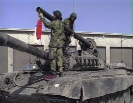

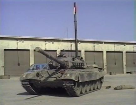
The two photos below shows the snorkel being installed during a river crossing exercise.


The maximum distance that can be traveled underwater by snorkeling is 1,000 meters. Needless to say, the further the distance, the greater the danger of the operation. Operationally, however, the capability to cross large water obstacles was indispensable.

Only crews that have passed a water obstacle crossing training programme and have taken part in exercises are allowed to undertake such maneuvers. If radio communication between the tank crew and ground units is interrupted while the tank is snorkeling, it is possible to communicate by passing an antenna up the snorkel. Depending on the situation, the crew may have to bail out of the tank while it is underwater. To do this, the bilge pump is deactivated and the TKN-3 periscope and the TNPO-168V periscope are both pulled out of their respective ports to allow water to flood the tank. Flooding the tank this way takes 1.5 minutes, and after the tank is completely flooded, each members exit the tank through their own hatches. Prior to this, the crew must perform a few safety tasks, like switching on the emergency lighting in the tank, switching off the battery system, releasing the parking brake, or disconnecting their communications devices from the intercom system and taking off their helmets (if IP-5 is not already worn prior to entering the water).

FUEL TANKS

Different grades of diesel may be used depending on the weather conditions. In non-winter weather conditions where the ambient temperature is above 0°C, the DL grade "summer" diesel fuel is used. It has a density of 0.86 kg/liter at a nominal temperature of 20°C and has a flash point of 62°C. In winter conditions where the ambient temperature is -30°C and above, the DZ grade "winter" diesel fuel is used. It has a density of 0.84 kg/liter and has a flash point of 40°C. In arctic conditions where the ambient temperature is -50°C and above, the DA grade "arctic" diesel fuel is used. It has a density of 0.83 kg/liter and has a flash point of 35°C. The DA grade is essentially a slightly heavier form of kerosene. If the temperature drops below 0°C during the course of an operation and DZ grade fuel is not immediately available to a tank unit, it was possible to adapt DL grade fuel for winter use in field conditions by adding kerosene. Alternatively, it is also possible to switch from diesel to TS-1 kerosene (jet fuel) as all T-72 engines have a multifuel capability.
All T-72 variants have a total internal fuel capacity of 705 liters spread across several fuel tanks. Two fuel tanks are located on the two front corners of the hull (flanking the driver). The port side fuel tank (17) extends from the nose of the glacis up to the turret ring and the starboard side fuel tank (18) extends from the nose of the glacis up to the driver's station. Though it has a cutout for the driver's instrument panel, it has a voluminous capacity of 475 liters. The starboard side fuel tank has a capacity of only 158 liters due to the deep cutout for the firefighting system control units, detection and control units for the NBC protection system, and a power supply unit. The fuel level, as displayed to the driver on his instrument panel, is measured by from these two fuel tanks, each equipped with an electronic fuel meter. Behind the starboard side fuel tank is another fuel tank (3) with slots for ammunition. It has a capacity of 237 liters. The crescent-shaped conformal fuel tank directly behind the autoloader carousel, which holds 12 propellant charges, has a capacity of 75 liters. These internal fuel tanks are made from stamped sheet steel with a bakelite coating.

Another 495 liters of fuel is stored in conformal fuel tanks located externally on the starboard side fenders above the tracks. As the diagram above shows, the external and internal fuel systems are not interconnected. They each have their own separate fuel lines, but both connect to the same fuel pump.
These fuel tanks are made from stamped aluminium with an internal bakelite coating and have internal partitions to reduce sloshing. Fuel from the sponson tanks are drained sequentially, beginning with the front tank and ending with the last tank from, as the fuel line is connected to the last tank while the first tank is connected to an air line. With this arrangement, the puncturing of the front tanks does not drain the tanks behind, so that the loss of the entire bank of fuel tanks on the sponson from combat damage is unlikely. The fuel hose between two external fuel tanks can be seen in the photo below.


The total fuel capacity of the T-72 is 1,200 liters. In the summer, the 1,200 liters of fuel carried in a T-72 weighs 1,032 kg.
Due to the radiation absorbing properties of fuel, it was found that the frontal fuel tanks gave the driver considerable protection from gamma radiation. As such, the front fuel tanks were designed to be drained last. This also has the added bonus of providing additional protection from spall and secondary fragments during combat, especially in conjunction with the 45mm of anti-radiation lining on the hull sides, as it is generally quite unlikely for the tank to be nearly running out of fuel during combat. In an emergency, if any other tank is damaged, 90-100 liters of diesel in the left front fuel tank is sufficient for 1 hour of continuous driving.
Being entirely separated from each other, the driver is able to shut off and isolate the internal and external fuel tanks from his station. Isolated fuel tanks will be disconnected from both the fuel pump and the air return lines, so the fuel within the tank will be left to sit. This can be beneficial in some circumstances, such as when there is an imminent threat of an internal fire spreading. By shutting off all of the internal fuel tanks, the fuel will not leak out as energetically as it is no longer being drawn by the fuel pump or maybe even stop leaking entirely, depending on the specific location of the damage to the tanks. Without an air return line, a fire in the fuel tanks will extinguish itself rapidly as it consumes the limited volume of oxygen available.
It is also possible for the driver to shut off all internal fuel tanks, and rely on external fuel only if the situation allows it. This keeps the internal fuel tanks full and prevents the tanks from being filled with air, so that the chances of an internal fire or explosion are minimized.
The video below shows a T-72B in Grozny retreating with some of its external sponson fuel cells alight. As you can see, the tank is not disabled by the fire and is perfectly capable of moving under its own power to a safe location where the crew can put out the fire with the fire extinguishers carried inside the tank.
Two externally mounted auxiliary fuel drums can be carried on special mounts at the rear of the tank. The auxiliary fuel tank holders are hinged, and may be folded flush to the hull rear when not in use. The standard drums fitted to each T-72 have a capacity of 275 liters and are connected directly to the fuel system, and both can be disconnected by the driver at the same time by the push of a button. With these drums fitted, the maximum fuel capacity of the T-72 is increased to a total of 1,750 liters. Alternatively, it is also possible to use generic 200-liter capacity drums, giving a smaller total capacity of 1,600 liters.
.jpg)
On highways, the T-72 Ural and T-72A can travel 480-500 km on internal fuel alone or around 700 km with additional fuel drums. With the standard 275-l drums, a range of 730 km is possible. With 200-l drums, the range is around 670 km. It is stated in the book "Боевые Машины Уралвагонзавода: Танк Т-72" published by the Uralvagonzavod Production Association, that when using petrol (A-72), the driving range is reduced by 20%. The fuel consumption of a T-72 Ural is 2.4 l/km when driving on paved roads, higher than the T-64A with the less powerful 5TDF engine; a fuel consumption of only 2.0 l/km was recorded during the same tests. However, the T-72 achieved better performance during offroad driving - the fuel consumption was 2.6-4.5 l/km, whereas a figure of 3.0-4.5 l/km was recorded for the T-64A.
Thanks to improvements in fuel efficiency on the
T-72B3, it can travel 550 km on internal fuel alone or 800 km with
external fuel drums despite having the same fuel capacity as older models. As with all automobiles, fuel efficiency decreases significantly while driving cross-country because the amount of engine power needed to overcome dynamic resistance increases as the harshness of the terrain increases, and so does fuel consumption.
Because of the T-72's relatively large fuel capacity and high fuel efficiency, refueling the T-72 isn't even necessary for short continuous operations. This greatly eases the logistical burden on the frontlines.
Because of the T-72's relatively large fuel capacity and high fuel efficiency, refueling the T-72 isn't even necessary for short continuous operations. This greatly eases the logistical burden on the frontlines.