ZETs11-3

The firefighting equipment of the T-72, or "PPO" (ППО - Противопожарное Оборудование), consists of the ZETs11-3 automatic system and one or more portable fire extinguishers. The ZETs11-3 system was the firefighting system of the T-72 tank series throughout its entire career in the ground forces of the Soviet army from 1973 until 1992, when the Soviet army was disbanded. It continued to be used in legacy tanks operated by the Russian army. It is an automatic firefighting system protecting both the crew and engine compartments, with the option of manual control by any of the three crew members. In most respects, the ZETs11-3 system does not differ from the original ZETs11 system previously fitted on the T-64, with the only exception that Composition "3.5" was used as the fire extinguishing agent in the ZETs11 system, whereas Freon 114B2 is used in ZETs11-3. The same change was implemented on the T-64 series, with the T-64A being fitted with the ZETs11-2 system featuring Freon 114B2 beginning in July 1973, and the T-80 also having the ZETs11-2 system when it entered service in 1976.
The system is waterproof, and it functions within an environmental temperature range of -50°C to +50°C. The system operates at a nominal voltage of 27 V, consumes no more than 35 W of power, and is wired to the batteries of the tank with two-wire cabling, grounded via the tank hull itself.
The ZETs11-3 system consists of:
- B11-5-2S1 control unit
- P11-5 control and display panel
- KUV11-6-1S ventilation control unit
- TD-1 thermal sensors
- Halon extinguisher bottles
- Spares and accessories kit
Fundamentally, the function of the system is to detect a fire and automatically provide the total flooding of the affected compartment with the extinguishing agent to extinguish any fire detected within, and suppress the start of any additional fires that may potentially occur.
One of the main difficulties with combating fires in tanks with an automated system is that the interior is filled with people and equipment, and the shape of the vehicle structure itself interferes with the line of sight between a fire and the extinguisher dispensers, which are fixed. This essentially limits automated systems to the total flooding method, which means that the agent fills the entire three-dimensional volume and can enter all nooks and crannies. However, it is worth noting that total flooding is only partially achieved in the system, as the spray nozzles that dispense the extinguishing agent are all placed in the hull, and given that the extinguishing agent is heavier than air, this can lead to uneven concentration levels between the hull and turret sections of the crew compartment. In the fire protection industry, total flooding is normally achieved with ceiling nozzles to allow the extinguishing agent to traverse the entire height of the room or compartment, even if the probability of a fire near the ceiling is drastically lower than on ground level, which is also true in the case of tanks.
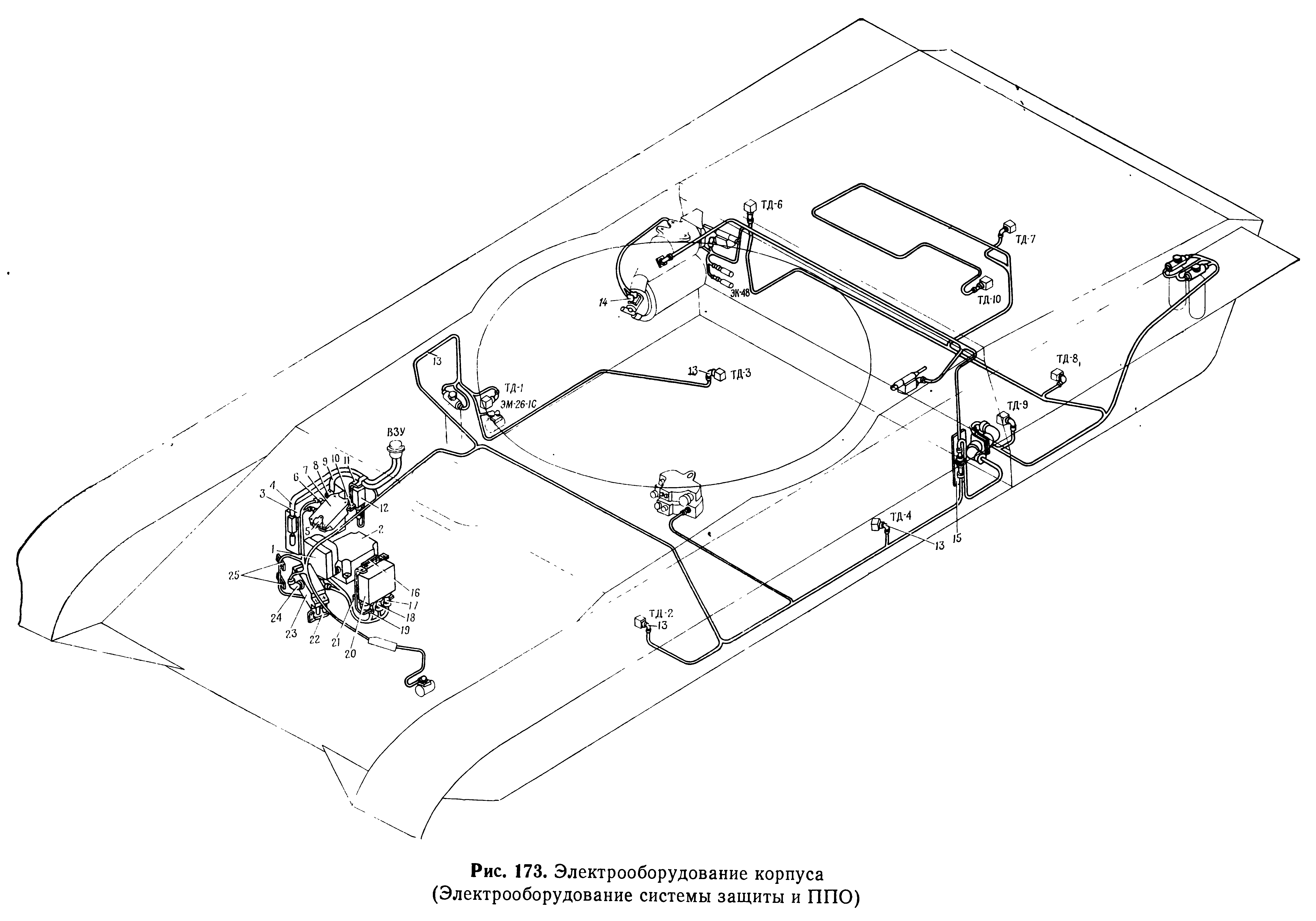
In addition, the tank is provided with a portable fire extinguisher to fight small fires which may have gone undetected by the thermal sensors. The portable fire extinguisher may also be used to handle fires outside the tank, and it remains a backup option for fighting internal fires after the bottles integral to the automatic firefighting system have all been spent. In most T-72 models, including Soviet T-72, T-72A, export or licence-produced T-72M, T-72M1 and Yugoslavian T-72 (M-84) tanks, one OU-2 carbon dioxide fire extinguisher is carried in the tank. It is stowed on the side guard of the autoloader carousel, behind the driver's seat and escape hatch. This is mentioned in various manuals and texts, and is depicted in a technical drawing valid for the T-72 as of 1.1.1978, shown below. It is worth noting that there is a bottle stowed on the rear right fuel tank-ammunition rack that looks like a fire extinguisher, but is actually a decontamination sprayer. It is painted in a dark olive colour, while all fire extinguishers are red.

At some point, this was changed to two OKh-2 halon fire extinguishers, containing either Freon 114B2 or Freon 13B1. The bottle contains 2.0-2.1 kg of the halon agent. There is a high-pressure nitrogen chamber inside the bottle, containing nitrogen pressurized to 45 kgf/sq.cm. One of the halon extinguishers is carried internally, replacing the CO2 fire extinguisher, but the location of the other is unclear. Judging by the stowage layout used in later tanks, it may be stowed in the left small compartment in the center rear turret bin. It is possible that this change was made in the early 1980's as part of the implementation of the "Soda" anti-napalm suite. The additional fire extinguisher may have been stowed outside the tank with the main goal of extinguishing external fires, allowing the internal extinguisher to be reserved for internal fires.
The portable fire extinguishers are not considered to be part of the ZETs11-3 system, but rather, are part of the spare parts and accessories kit (ЗИП) of the tank.
The firefighting system is hard-wired to the reserve power supply network, so it is turned on when the master power switch is pressed. As such, when the master power switch is pressed to start the engine in a T-72, the ZETs11-3 system will already be turned on. Although the ZETs11-3 system is wired to the reserve power network, it also works when the tank batteries are discharged because the reserve power network is also connected to the alternator. As such, it is quite likely for the fire extinguishing system to be operational at virtually all times. In combat, the physical isolation of the batteries from the engine by a large distance may be considered to be a safety measure of sorts, as it makes it unlikely for both power sources to be knocked out simultaneously by a single attack on the tank.
The system can work two modes: automatically or manually. The default mode is automatic, with the option of manual activation at all times by any of the crew members. The driver controls the firefighting system via the P11-5 control and display panel. The commander and gunner both have an emergency extinguisher activation button on their master control panels. There is no way to turn the ZETs11-3 system off other than to turn off the master power to the tank. However, the firefighting system can be switched to the OPVT mode (underwater mode) via the P11-5 control panel by flipping the toggle switch from "PPO" to "OPVT". The OPVT mode blocks the engine stopping system, and prevents the fire extinguisher bottles from discharging when a fire is detected in either the crew or engine compartment. Only the visual fire alarm system is permitted to function. Technically, nothing prevents the driver from switching back to the PPO mode while the tank is underwater, and activate the firefighting system, but doing so will violate snorkelling safety protocols.
The P11-5 control and display panel serves as the main interface for controlling and self-testing the firefighting system. The panel has seven indicator lights. The three lights on the top row (3, 5, 6) are to inform the driver of the serviceability of the pyrotechnic fire extinguisher valves, the left light on the second row (2) indicates the presence of a fire in the fighting compartment, the center light on the second row (4) indicates the presence of a fire in the engine compartment, the light on the right (7) indicates the status of the overpressure system (on or off), and the light on the third row (12) indicates if the OPVT mode is activated. By referring to indicator lights (2) and (4), the driver can manually discharge the fire extinguishers for either the fighting compartment or the engine compartment by pressing the buttons (1) and (15), which are located behind a hinged metal cover.

The P11-5 has two fuses, a 10 A fuse (13) and a 2 A fuse (11). These fuses block the circuit for the third extinguisher bottle from activation. It is only when one of the fuses is burned out by the activation of one of the other two extinguisher bottles that the circuit of the third bottle is opened, allowing its use. When the 10 A and 2 A fuses are in good condition, power is supplied to a relay which keeps the emergency activation circuit of the third cylinder disconnected. When one of the fuses burns out, the relay releases its contacts, closing the switch of the emergency circuit, allowing the driver to discharge the bottle in either the crew or engine compartment manually by pressing the corresponding button on the P11-5 panel.
The location of the P11-5 can be seen in the image on the left below.


Besides its independent role as the firefighting system, ZETs11-3 is also integrated into the NBC protection suite of the tank, as there are a number of control devices shared between the two systems. In this application, the B11-5-2S1 control unit is subordinated to the GD-1M gamma sensor of the NBC protection system, serving as the control module for sealing the tank, shutting down the engine, and turning on the filtered overpressure system via the KUV11-6-1S ventilation system control unit. ZETs11-3 is also connected to the tank intercom system, to broadcast alarms when a fire or NBC threat is detected.
When a fire protection protocol and an NBC lockdown protocol with conflicting procedures are active at the same time, the firefighting system takes priority; the control flow of the firefighting system must conclude before the NBC procedure control begins.
The TD-1 sensor used for fire detection was inherited from the "Rosa" standardized firefighting set implemented in Soviet tanks in 1958. The sensor works using fifteen chromel-copel thermocouples wired in series. The hot junction of a thermocouple is exposed to the internal environment of the tank and is seen as a protruding triangle. The cold junction is embedded inside a white epoxy-based insulator block. The thermocouples in the TD-1 can be heated via direct flame, thermal radiation, or by convection, and the response time is essentially dictated by the speed at which the critical threshold is reached. This, in turn, will depend on the heat and distance of the flame.


Because it can sense a fire by both direct and indirect heating, the TD-1 functions in relatively wide detection arc, but the timeliness of detection can vary greatly.
Nine TD-1 sensors are arranged in the crew compartment, and five TD-1 sensors are arranged in the engine compartment. Most of these are shown in the diagram below. The placement of each sensor was chosen based on the zones with the largest fire hazard; over half of the sensors in the crew compartment are concentrated around the rear fuel tank-ammunition rack. Although this fuel tank is not particularly likely to be a fire hazard, the consequences of a fuel fire in this region are probably the most serious, because the fuel tank holds 12 propellant charges and there is a large quantity of ammunition near it. In the engine compartment, the sensors are placed to monitor oil, hydraulic and fuel lines.

Seven of the TD-1 sensors in the crew compartment can be seen in the photo below. There are three around the rear hull fuel tank-ammunition rack, one next to the heater, one under the autoloader carousel, one next to the front right fuel tank-ammunition rack, and one next to the hydraulic turret traverse drive.

The fire fighting system reacts regionally when a temperature difference of at least 150°C (cumulative 98 mV) is detected by at least one TD-1 in the crew compartment or engine compartment. Once a fire is detected by any of the TD-1 sensors, the maximum response time of the rest of the system is 50 milliseconds.
One of the reasons for the use of thermocouple technology in this application is their ability to self-adapt to wildly varying operating temperatures; depending on the location of the sensors and the local environment that the tank is operating in, the hot and cold junctions of the thermocouple will eventually equalize in temperature according to the ambient temperature inside the tank. For example, in winter, a TD-1 sensor monitoring the tank heater will be slowly warmed up by the boiler and convection from the heater fan, so both the hot and cold ends of its thermocouples will have time to equalize, and the temperature difference between the hot and cold ends will still be the same as another TD-1 sensor on the far end of the tank which is barely heated by the heater. Because of this, the TD-1 sensors also ensure reliable fire sensing in the engine compartment, where the ambient temperature can be very low but eventually rise to a very high temperature after a period of driving. The sensor only registers a fire if there is a sudden, rapid rise in temperature, characteristic of an open flame.
The functioning of other types of thermal sensors in the engine compartment, such as the bimetallic strip sensors used in the earliest T-54 tanks, can be complicated by this severe operating environment, as each sensor may need to be calibrated to account for their specific environment, and at the same time, increasing tolerance decreases sensitivity and therefore, the timeliness of fire detection.
In the event of a fire in the crew compartment, the thermocouples of the nearest TD-1 sensor are heated until the voltage threshold is crossed, signalling the presence of a fire. The TD-1 sensor then delivers an activation signal to the B11-5-2S1 control unit. If the ZETs11-3 system was set to work in the automatic mode, then the following sequence of events will occur:
- The tank engine stops
- The ventilation intake is closed, and if it was turned on, the supercharger is stopped
- The release squib of cylinder No. 1 is triggered, releasing the fire extinguishing agent into the crew compartment pipelines
- The fire alarm in the crew compartment is activated*
- Expended bottle is marked as empty (corresponding lamp on the P11-5 unit goes out).
*The alarm consists of a sound alarm transmitted to the headphones of all crew members and an indicator light for the compartment being turned on
If the system fails to extinguish the fire, the thermal sensor continues to heat up, triggering the system to discharge cylinder No. 2 (lamp 2B goes out on the P11-5 panel), and if it continues, then cylinder No. 3 is discharged (lamp 3B goes out on the P11-5 panel). If the fire is extinguished, then after 30-50 seconds, the ventilation supercharger is automatically turned on and the fire alert lamp for the crew compartment on the P11-5 panel goes out. At this point, the firefighting system cycle is concluded. After ventilation, the supercharger is turned off, or if it was previously turned on, then it remains on. If the first fire was successfully extinguished, but a fire occurs again, the process repeats itself from the beginning.
The delay of 30-50 seconds is also referred to as the cycle time of the system. It could be surmised that the reasons for a built-in delay of 30-50 seconds may be to ensure that the extinguishing agent has propagated adequately to properly extinguish a fire and to suppress any further fires, and also to leave a monitoring period for the sensors to confirm if the fire was extinguished or if there is another fire.
According to the guidelines, when extinguishing a fire in the crew compartment, the crew can remain in their places, hold their breath, open their hatches and breathe through them, or hold their breath and put on their gas masks. The last option is to be done in a combat situation. If the situation permits, the crew should leave the tank and close the hatches behind them, and wait until the crew compartment is completely ventilated before re-entering the tank. The crew should not stay in the tank while keeping the hatches open, as this allows the fire extinguishing agent to vent out to the atmosphere, reducing the effectiveness of the extinguishing agent and potentially allowing the fire to reignite. If the crew chooses to stay inside the tank, they can continue to take part in combat; aside from the stopped engine, all other systems in the tank are fully operable.
In the case of a fire in the engine compartment, the system works in the same way, but the fire extinguisher is discharged only after the engine and the cooling fan are completely stopped, and the cooling fan vent louvers are sealed. The partial sealing of the engine compartment helps to starve the fire of oxygen from the environment and prevents the loss of the extinguishing agent into the atmosphere, which would reduce its concentration and thus its effectiveness. Nothing needs to be done by the crew when the system is extinguishing a fire in the engine compartment.
It is worth noting that some of these subroutines are also used by the NBC protection system. For example, the same subroutine of turning on the supercharger after 30-50 seconds is also used in the nuclear protection protocol of the NBC protection system.
The large variance in the delay periods is likely because analogue time delay circuits are used. Such circuits use the charging time of a capacitor(s) to create a time delay. Charging time can be affected by changes in capacitance and the resistance of resistors in the circuit due to widely differing operating temperatures, which can be seen as a byproduct of the severe operating temperature range of -50°C to +50°C dictated by military requirements. In practice, delay times should be fairly consistent for a single given environmental temperature.
EXTINGUISHING SYSTEM
There are a total of 26 spray nozzles, 14 of which are in the crew compartment and 12 are in the engine compartment. Most of the nozzles are close to the floor.

Each Freon 114B2 bottle has a 2-liter capacity, and the content of the fire extinguishing compound weighs 1.2-1.3 kg. To increase the flow rate of the extinguishing agent, there is a high-pressure nitrogen chamber inside the bottle, containing nitrogen pressurized to 70 kgf/sq.cm. The first two bottles are always used first. The third fire extinguisher bottle is an emergency reserve, which only becomes available if one of the other two bottles has been spent.


The fire extinguisher bottle is discharged by means of a pyrotechnic squib, which propels a striker into the sealing membrane of the bottle vent. The striker pierces the membrane, and is subsequently blown back by the release of the pressurized fire extinguishing agent, which flows into the pipelines of either the crew compartment or engine compartment. Any of the three fire extinguisher bottles can be switched to discharge into either the crew compartment of the engine compartment. This is done by having a double-ended top, with one port connected to the crew compartment pipeline and the other connected to the engine compartment pipeline. The selection of the pipelines is done by simply selecting which membrane is pierced.

Freon 114B2, also known as Halon 2402, is capable of handling class A, B, C and electrical fires. It leaves no residue and does not affect electrical equipment. Like other halon extinguisher compounds, it is ideally used as a total flooding agent in confined spaces with poor ventilation. Prior to its use in tank firefighting systems, it was used in other high-value military assets, including buildings, ships, submarines, and aircraft. It is reported in UNEP Technology and Economic Assessment Panel (1994) that Russia was, and still is, the largest user of Halon 2402, and that its use has by far been in critical military applications, including top-priority premises. In this context, the choice to use Halon 2402 in tanks such as the T-72 was a fairly conservative one.
According to information cited in a study by Humphrey, Smith & Skaggs (1990, pp. 2-3), Halon 2402 is a particularly effective fire extinguishing agent, surpassing Halon 1301 (Freon 13B1) and Halon 1211 (Freon 12B1, also known as BCF).
A number of studies have shown that Halon 2402 is more effective than either Halon 1301 or Halon 1211 in extinguishment of most types of fire. The higher effectiveness of Halon 2402 is due to both physical and chemical properties. Its higher boiling point, lower vapor pressure, and higher density permit a longer throw range, less dispersion during delivery, lower buoyant losses owing to fire updrafting, and improved securing ability. These characteristics make Halon 2402 particularly effective against deepseated fires, outdoor fires in unfavorable ambient conditions, large buoyant fires, and Class B fires, where there is danger of burnback. The larger bromine content per molecule (compared to Halons 1301 and 1211) gives Halon 2402 an improved extinguishment capability since hydrogen bromide, formed during agent use, is the primary free radical terminator effecting suppression.
However, a glaring issue with the use of this gas in the crew compartment of a confined space, such as that of a tank, is its high acute toxicity. Although the health effects of Halon 2402 inhalation exposure over a standard 4-hour period has been ascertained in toxicity studies with various animal test subjects, case studies on the effects of very-short term Halon 2402 inhalation exposure on humans in the context of a tank firefighting system are not available to the public. It is known from at least one conference paper (Dodd & Vinegar 1999, p. 234) that the 50% lethal concentration is approximately 120,000 ppm for a 15-minute inhalation exposure period, with rats as the subjects. This is drastically lower (more toxic) than Halon 1301 (800,000 ppm), but only somewhat lower than Halon 1211 (200,000 ppm). The same data was used in a research paper (Dodd, Jepson & Macko 2000, p. 18) for the Next-Generation Fire Suppression Technology Program (NGP). Considering that the mass of free air inside the tank is under 7.53 kg (given standard air density of 1.225 kg/cu.m, empty volume of 7.9 cu.m, 705 liter capacity of internal fuel tanks, and 500 liters occupied by 125mm ammunition), 1.2-1.3 kg of Halon 2402 discharged into the crew compartment results in a nominal concentration of no less than 160,000-170,000 ppm. The mass of the nitrogen discharged into the crew compartment is considered negligible.
From this, it is easy to infer that it is an extreme health hazard to be sealed inside the tank for any duration, but due to the forced ventilation of the crew compartment less than a minute after the extinguisher discharge, it seems unlikely for a death to occur, particularly for the crew members in the turret, but severe nervous and respiratory incapacitation can be expected for the driver, who is likely to inhale a substantially larger dose than the other two crew members. It is known from experiments by the National Institute of Standards and Technology (1990) in the U.S that human exposure to even a low concentration of 2,200 ppm for 2 minutes causes disorientation, dizziness, and the inability to maintain balance.
On the other hand, the very high effectiveness of Halon 2402 is not counterbalanced by any toxicity issues when it is used in the engine compartment. Moreover, due to the use of a standard set of fire extinguisher bottles for both the crew compartment and engine compartment, the concentration of the Halon 2402 agent in the engine compartment will be exceptionally high, owing to the much smaller volume of air. For reference, the empty volumes of the crew compartment and engine compartment are 7.9 cubic meters and 3.1 cubic meters respectively, but the engine compartment is much more tightly packed, such that the mass of free air inside the engine compartment will be 5-10 times smaller than in the crew compartment.
ZETs13-1

Introduced to the T-72 series with the T-72BA modification, which began deliveries to the army in 1999-2000, the ZETs13-1 system was a Soviet era system previously fitted to the T-80U, and then T-90. It is also fitted to the T-72B3. From 1999 to 2011, T-72B tanks brought in for a total overhaul may be modernized to the T-72BA standard, whereupon its firefighting system would be upgraded to the ZETs13-1. From 2011 to the present, T-72B tanks may be modernized to the T-72B3 standard instead, and receive the ZETs13-1 system as part of that process.
The ZETs13-1 functions as a conventional firefighting system in the engine compartment, and as an explosion suppression system in the crew compartment. To that end, the design of the sensing system, the fire extinguisher bottles, and the dispensers in the ZETs13 system differs considerably from the ZETs11. The interface was also improved. The firefighting system, consisting of both the integrated system and the portable fire extinguishers carried in the tank, is intended for combating fires inside and outside the tank. In addition, to extinguish a fire inside and outside the tank, including napalm-type fire mixtures, there are two portable fire extinguishers.
The system is waterproof, and it functions within an environmental temperature range of -50°C to +50°C. The system operates at a nominal voltage of 27 V, consumes no more than 35 W of power, and is wired to the batteries of the tank with two-wire cabling, grounded via the tank hull itself.
It can function in three modes: automatic, semi-automatic and emergency. The automatic mode, which is the default mode, is active when the master power switch of the tank is turned on and operates without human intervention. It functions identically to the ZETs11-3 system. The semi-automatic mode is effectively the same as the automatic mode, except that the discharge button for a fire extinguisher bottle is manually pressed before the system discharges it, or if the system has failed to do so automatically. The emergency mode is the same as the semi-automatic mode, except that it is characterised by the failure of the system to issue a fire warning, or if one of the two fuses have burned out.
The ZETs13-1 system consists of:
- B13 control box
- P13 control and display unit
- Ventilation control box KUV11-6-1S
- Dynamic braking box K11
- Halon extinguisher bottles
- Spares and accessories kit
The B13 control unit fulfills the same role as the B11-5-2S1 control unit, and the P13 control and display unit fulfills the same role as the P11-5. The P13 is shown in the image below. P13 replaces the simple incandescent indicator light bulbs on the P11-5 with a backlit display, but other than this, the new panel is functionally the same as the P11-5. A close look shows that besides the new display, the buttons, toggles and other interactive components are exactly the same as in the P11-5. A P13 control panel can be seen tucked away at the right side of the photo below. Photo taken from Popular Mechanics Russia.


The visual alarm system was also improved - now, the driver is also alerted by all of the indicator lights next to his TNPO-168V periscope being turned on, in addition to the alarm light on the P13 display and the audio alarm. Another additional feature is that the tank commander is also provided with a visual alarm unit in his station to indicate if the fire is in the crew compartment or the engine compartment. Previously, he only had the audio alarm in his headset.
One of the crucial upgrades introduced by the ZETs13-1 system was the use of OD1 optical sensors. The OD1 sensor is comprised of two optical IR photodetectors oriented to cover an arc of 120 degrees. The photodetectors are sensitive to short-wave IR emissions produced by an open flame. The same optical layout is used in the explosion suppression systems in the M1 Abrams and Leopard 2. The use of optical sensors was neccesitated by the need to detect and identify the flame of a fuel explosion in its incipient phase, so that the fire extinguishing agent can be discharged into the fuel mist cloud before the cloud can be detonated by the flame front, thus suppressing the explosion. It is important to note, however, that ammunition fires and explosions still cannot be suppressed and are not extinguishable.

The sensor set consists of ten OD1 optical IR sensors in the crew compartment, and five TD-1 thermal sensors in the engine compartment. The TD-1 sensors in the engine compartment are in the same locations as they were in the ZETs11-3, and the layout of the engine compartment itself is unchanged in the various T-72 and T-90 models. The layout of the OD1 sensors is shown in the image below. The location of the sensors is very different compared to the ZETs11-3, as there is a larger emphasis on using the optical sensors to monitor the large free spaces where a fuel mist cloud can propagate and detonate, with fewer sensors tucked away in less accessible locations where a pool fire might develop; there are only two sensors in front of the rear fuel tank-ammunition rack and underneath the autoloader carousel.

The response time of the OD1 optical sensor between the eruption of a fire and its detection does not exceed 2 ms. For comparison, the detection period of the optical sensors in a Leopard 2A4 is 2.5-5 ms (Kowalski 2018, p. 33).
EXTINGUISHING SYSTEM
The 114B2 fire extinguishing agent was replaced by Freon 13B1, also known as Halon 1301. Four fire extinguisher bottles are provided in the system. Two of these are quick-discharge bottles designed to supress explosions and extinguish fires in the crew compartment, shown on the right below. The other two are ordinary bottles designed to extinguish fires in the engine compartment, shown on the left below. All bottles use Halon 1301 as the primary extinguishing agent. Unlike the ZETs11-3, the pipelines of the fire extinguisher bottles in the crew compartment and engine compartment are not interlinked. The bottles in the crew compartment service only the crew compartment, and vice versa.


Both of the two quick-discharge bottles are located in the crew compartment; cylinder No. 1 is placed behind the front right fuel tank-ammunition rack, and cylinder No. 2 is placed behind the driver's seat, on the side guard of the autoloader carousel. Each bottle contains 1.9-2.0 kg of Halon 1301. To increase the flow rate of the extinguishing agent, there is a high-pressure nitrogen chamber inside the bottle, containing nitrogen pressurized to 75 kgf/sq.cm. The nitrogen has a supplementary extinguishing effect, as it displaces oxygen.
The system is rated to discharge 90% of one quick-discharge fire extinguisher bottle within 100 milliseconds upon detection of a fire. According to one Polish document (Kowalski 2018), the required reaction time for explosion suppression is 150 milliseconds. It is also known from other sources (Booz, Allen & Hamilton Inc. 2003, p. 17) that the U.S Army considered it necessary to extinguish a fuel explosion within 250 milliseconds on the basis that doing so will effectively suppress it.
The Army has determined that if the mist fireball explosion can be suppressed within 250 ms from the time the weapon strikes the vehicle, there will not only be no sustained fire, but personnel present in the compartment will receive no worse than first degree burns (comparable to a mild sunburn) on exposed skin. Therefore, the requirement is that the mist fireball explosion be extinguished within 250 ms. Current halon 1301 automatic fire extinguishing systems can meet this requirement, often exceeding it by 100 ms.
The ordinary extinguisher bottles used in the engine compartment are placed on the left rear corner of the engine compartment, in the same location as their counterparts in the ZETs11 system. These bottles hold 0.58-0.62 kg of Freon 13B1 and also contain a high-pressure nitrogen chamber, with nitrogen pressurized to 70 kgf/sq.cm.
Based on the weights of the fire extinguishing agent in the two types of extinguisher bottle, it can be seen that the volume of Halon 1301 used to extinguish fires in the crew and engine compartments is closely proportional to the amount of free air in these spaces. The crew compartment has a volume of 7.9 cubic meters while the engine compartment has 3.1 cubic meters of volume, within which there is only a small amount of free space, as approximately 1.2 cubic meters is occupied by the engine, and 0.43 cubic meters is occupied by the transmission. Other devices such as the air compressor, air cleaner, the radiators, the coolant reservoir, oil reservoir, etc. reduce the free space in the engine compartment to an absolute minimum. From this, it can be estimated that proportionately, the concentration of Halon 1301 discharged into the engine compartment will be at least comparable to the concentration in the crew compartment, and likely higher.
Assuming a free air volume of approximately 0.6-0.8 cubic meters in the engine compartment, the concentration of Halon 1301 alone (excluding the nitrogen) will be 60-80% by weight, or 11-14% by volume, given vapour density of 5 (OSHA c. 2001). For perspective, it is important to note that only a little over 3% by volume is required to extinguish a fire (Meserve & Parsons).
Lastly, the two portable fire extinguishers each contain 2.0-2.1 kg of Halon 1301. There is a high-pressure nitrogen chamber inside the bottle, containing nitrogen pressurized to 45 kgf/sq.cm. One portable extinguisher is secured to the autoloader carousel side guard, next to cylinder No. 2 of the ZETs13-1 system. The other portable extinguisher is stowed outside the tank, in one of the small compartments of the center rear stowage bin on the turret rear. The main purpose of the external extinguisher is for extinguishing external fires.
Studies on the effectiveness of Halon 1301 as a fire extinguishing agent in the T-72 are not available. As a point of reference, the effectiveness of the firefighting system in the M1 and M1A1 Abrams was found to be rather underwhelming; in the study by Booz, Allen & Hamilton Inc (2003, p. 13), peacetime fire incident data for the years 1988, 1989, 1990 and the first half of 1991 showed that the AFES system was only activated 71 percent of the time for M1/M1A1 fires and it was adequate to extinguish the fire by itself only 34 percent of the time. This data cannot serve as a direct proxy for the T-72 or T-90, as it was noted in the study that the fire extinguishing system of the Abrams is ineffective at combating V-pack (dry element, fiber-based air cleaner for the engine) fires, which is a type of air cleaner that is not present in the T-72 or T-90.
REFERENCES
Макаренко А & Кузнецов Ю, Электроспецоборудование танка Т-72: Учебное пособие 1999, Военная кафедра Омский Государственный Технический Университет, Омск
Министерства обороны СССР, Каталог деталей и сборочных единиц Танк Т-72 1980, Военно Издательство, Москва
Министерства обороны СССР, Танк Т-72М1 Техническое Описание И Инструкция По Эксплуатации (Часть I), Военно Издательство, Москва
Министерства обороны СССР, Танк Т-72А Техническое описание и инструкция по эксплуатации 1988, Военно Издательство, Москва
Министерства обороны СССР, Танк Т-72B Техническое описание 2002, Военно Издательство, Москва
Янковский, ИН, Ильющенко, Д. Н, Гладкий, ДВ, Рябинин, СА, Ячник, АН & Андрукович, СН, Учебное пособие по дисциплине «Устройство бронетанкового вооружения» для курсантов, обучающихся по специальности 1-37 01 04 Многоцелевые гусеничные и колесные машины (по направлениям) направления специальности 1-37 01 04-02 Многоцелевые гусеничные и колесные машины (эксплуатация и ремонт бронетанкового вооружения и техники) 2019, Белорусский Национальный Технический Университет, Минск
Kowalski, K, Automatyczne systemy przeciwpożarowe w wojskowych pojazdach bojowych 2018, Zeszyty Naukowe SGSP 2018, Nr 65 (TOM 2)
Humphrey, BJ, Smith, BR & Skaggs, SR, Toxicity of Halon 2402, ESL-TR-88-59
Dodd, DE & Vinegar, A, 'Toxicity Data Comparison of Cf3i With Currently Used Fire-Extinguishing Agents And Refrigerants Of Interest To The Military', Halon Options Technical Working Conference, New Mexico, p. 234.
Dodd, DE, Jepson, GW & Macko Jr, JA, Human Health Safety Evaluation of Halon Replacement Candidates: Final Report – Section II of II.
United States Department of Commerce 1990, Preliminary Screening Procedures and Criteria for Replacements for Halons 1211 and 1301, NIST Technical Note 1278, viewed 21 March 2022 <https://www.govinfo.gov/content/pkg/GOVPUB-C13-8ed5cce9f9b0b7a510074b0e84774a58/pdf/GOVPUB-C13-8ed5cce9f9b0b7a510074b0e84774a58.pdf>.
Meserve, W & Parsons, M, Aircraft Fire Protection: A Critical Halon Application, Pacific Scientific
OSHA Office of Training and Education c. 2001, Common Fire Extinguishing Agents, U.S. Department of Labor, booklet
НПО «Электромашина», Система противопожарного оборудования 3ЭЦ11-3, viewed 20 March 2022, <https://www.npoelm.ru/product/spetsproduktsiya/sistemy-pozharotusheniya-ppo/sistema-protivopozharnogo-oborudovaniya-3ets11-3/>
НПО «Электромашина», Система противопожарного оборудования 3ЭЦ13, viewed 20 March 2022, <https://www.npoelm.ru/product/spetsproduktsiya/sistemy-pozharotusheniya-ppo/sistema-protivopozharnogo-oborudovaniya-3ets13/>
Booz, Allen & Hamilton Inc., Final Technical Report Fires Experienced and Halon 1301 Fire Suppression Systems in Current Weapon Systems 2003, Strategic Environmental Research and Development Program, The Department of Defense, Washington
Учебная дисциплина: Устройство базовыз Машин - Тема 12: Противопожарное оборудование базовых машин, ЮУрГУ Факультет военного обучения, Кафедра Танковых Войск
Лепешинский, ИЮ, Чикирев, ОИ, Варлаков, ПМ, Ануфриев, ЕВ, Мунин, ВА & Колобов, АА, Практикум по дисциплине «Устройство электроспецоборудования бронетанковой техники»: Учебное пособие 2012, Омск, Издательство ОмГТУ
When I saw this was separated out, I thought it would have some analysis of their use in the current conflict or is that still to come?
ReplyDeleteBecause we have a lot of videos despite selective editing showing the fire extinguishing systems activating and preventing catastrophic fires that blows the ammo, and what appear to be ERAs going off.
We also see Tanks taking multiple ATGM hits. And tanks eating an artillery round and dying horrifically.
Like I said, lots of selective editing, overclaims by Oryx who upon auditing of his work has overclaims of 30% on equipment where no Misattribution is possible and 50% where misattribution is possible, and on his claims of Russian T-64BV losses (scrapped or sold a decade ago), they clearly have Ukrainian Markings.
Makes it hard to sift fact from all the nonsense, but enough is coming out. Any plans to incorporate the revelations or are you going to wait till the shooting stops and we can get raw unedited footage to sift through?