
At present, the T-54 remains history's most enduring tank, and this is largely due to the sheer quantity of tanks used outside of the USSR. Besides the vast numbers of T-54 tanks fielded by the Soviet Army, thousands of tanks were exported and thousands more were produced by China. Dozens of variants of the basic model have been produced, most of them used by the Soviet Army. Production of the T-55 series for the Soviet Army continued until 1967 when it was fully replaced by T-64 and T-64A tanks, but it continued to be built for export clients until 1979, outlasting the T-62 which did not have the same level of export success.
As usual, we will only be covering the models used in the USSR but not abroad. We will be examining the most relevant variants of the T-54 except the models designed to fulfill supporting roles like firefighting and bridge laying.

There were a few prototype models, but the only one that made it to low rate production and small scale issuance was the T-54 obr. 1947, also known as the T-54-1. T-54-1 was first deployed to units in the Belorussian military district for crew familiarization and exercises, and it was there that a myriad of design flaws were discovered. As they were unfit for frontline use, most, if not all T-54-1s were relegated to reserves or storage soon after its more evolved brothers appeared. In the mid 60's, many T-54-1s and T-54-2s were taken apart and their turrets used as static pillboxes along the Chinese border and as coastal defence guns in the Far East.
Here are T-54-1 turrets installed on reinforced concrete pillboxes for coastal defence.


And here are T-54-2 turrets, one used for coastal defence and one on the border. Note the extremely small size and low height of the turret compared to the man.


The T-54 is a descendant of the legendary but obsolescent T-34, but after numerous revisions, the technical similarities between the two medium tank eroded away and the relationship between the two tanks had become purely historical by the early 1950's. Practically speaking, there was very little in common between the T-34 and the T-54 save that they both share roadwheels of the same diameter and the same track pin retention system (T-34-85 tanks stored in reserves were later modernized with T-54 roadwheels in the 1950's and 1960's). The noteworthy use of a transverse mounting scheme for the engine resulted in an enormous reduction in the volume of the engine compartment, leading to a cascading effect where the reduced volume also resulted in a reduced surface area that required armour protection, and the weight of the tank was consequently reduced. This freed up a considerably surplus of weight that could be distributed to other parts of the tank as additional armour thickness.

ERGONOMICS
Being smaller yet roomier and more thickly armoured than a T-34, the T-54 is excellent evidence that smaller tanks are not necessarily more cramped than a larger one. The main parameter is volumetric efficiency, in which the T-54 is rated highly. The total internal volume of the T-54 measured in at 11.4 cubic meters, of which 8.05 cubic meters forms the fighting compartment at the front and middle of the tank and the remainder forms the engine compartment. The share of the fighting compartment volume from the total volume is 71.25%, which is much higher than the 60.4% of the M47, 59.2% of the M48 and 60.7% of the M60A1. Of course, the volume of the T-54 fighting compartment is undoubtedly smaller than the aforementioned tanks in real terms: the M47 which is considered somewhat cramped compared to other Cold War era American tanks has a larger fighting compartment with a volume of 9.06 cubic meters. The roomy M48 has a fighting compartment volume of 10.48 cubic meters and the M60A1 is simply luxurious by comparison, having a fighting compartment volume of 11.17 cubic meters. Of course, one cannot ignore the fact that the M47 had five crew members and carried 71 rounds of 90mm ammunition as opposed to the four crew members of the T-54 and 34 rounds of 100mm ammunition, but the M48 and M60A1 have a clear and overwhelming advantage in terms of the volume allocated to each crew member. With this in mind, it can be said that the T-54 has a remarkably efficient allocation of volume and armour but with relatively little actual room due to the small overall size of the tank. Ideally, the efficient layout of the T-54 could have been scaled up, but the small silhouette of the tank was a serious advantage in terms of survivability at the time as it made the tank harder to hit, especially when it is moving.
Besides the volume allocated to the crew, it is also important to evaluate the furniture inside the tank as its design influences the comfort of the crew. In all T-54 and T-55 models, the turret occupants were seated on seats suspended from the turret ring. The gunner was separated from the D-10T gun by the built-in recoil guard of the gun itself, and a removable fence was attached to the recoil guard to keep the commander away from the recoil of the gun. The gunner's seat did not have a backrest.

Beginning with the T-55, a new recoil guard was added to the turret that separated the commander from the recoil path of the gun, and the gunner's seat received a backrest. The backrest was mounted to the seat cushion with a pole and it could be removed as the gunner moves from the commander's hatch to his station. However, it is often absent because it can impede a quick exit in an emergency.

The T-54 has a turret ring diameter of 1,825mm. In all incarnations of the turret design, the structure of the front half of the turret lies close to the turret ring but the structure rear half of the turret lies on top of a shelf. On the commander's side of the turret, this shelf space is taken up by the radio and control boxes, thus making up for the lack of a bustle. By right, the amount of room available in a T-54 turret should be at least comparable to a tank like, say, the Centurion MK. 2 and all subsequent models which shared the same cast turret, which had a 1.88 m turret ring, but as we know from actual comparison, that is not the case. This is at least partially due to the rather large breech of the D-10T gun and the lack of a turret bustle which was used to mount the radio (on the loader's side of the turret) in the Centurion, and more significantly, the commander in a Centurion is seated on top of the turret ring on the first step of the two-stepped turret bustle. This can be seen in the photo below.

With the commander seated this way, more space was created between the commander and gunner. This also allowed the gunner to have his own backrest - a luxury that the T-54 does not have. However, by placing the commander's seat in the turret bustle, the turret also had to be much taller to accommodate him; according to official drawings it is 959mm tall. This increased the overall height of the tank to 2,635mm when measured up to the turret roof, and the total height was 2,972mm. This also added weight; a combat-loaded Centurion Mk.3 weighed a whopping 50.8 tons - equal to a Soviet T-10 heavy tank and weighing 14 tons more than a T-54, yet having less armour than its Soviet medium tank counterpart, a less powerful gun, worse automotive performance, and a much worse travelling range. It was also not as roomy as an M48 Patton which still managed to weigh 5 tons less. Needless to say, there was no chance that such characteristics would have been acceptable for a Soviet medium tank.
The T-54 turret is slightly wider than the turret of an M46 which had a turret ring of only 1.75 m in diameter, and comparable with the M47, which had a turret ring that measures 1.85 m in diameter. A comparison between these tanks is fitting because they all have a similar needle-nose ballistic shaping with sloped turret sides, unlike the Centurion, which does not have significantly sloped plating on any facet of its turret. All of these tanks had rather narrow turret rings compared to the M48, as that had a 2,160mm diameter turret ring. In a comparison between the T-54 and its closest counterpart, the M48, the T-54 loses out in the amount of internal space available to the crew by a wide margin.

The low profile of the tank is advantageous when concealing the tank in prepared positions and it is also helpful if the tank is driving across open terrain as it reduces the likelihood of being hit, especially since tanks of that period had poor rangefinding capabilities, but the low profile is not so conducive for the loader. With a maximum internal height of only 1,600mm from the crew compartment floor to the turret ceiling, it was not possible for any of the crew members to stand upright in the turret unless they were particularly short. Nevertheless, the available internal height of the tank was considered enough for a loader by Soviet standards and the D-10T gun was designed with a horizontally-sliding breech as opposed to a vertically-sliding breech with this in mind. From this perspective, the T-54 is directly comparable to the M26 Pershing, M46 and M47 Pattons, but not the Centurion or the M48 Patton.
According to factory drawings, the Centurion has a total internal height of 2,057mm, but the tank stows a large quantity of ammunition on the floor of the hull underneath a rotating floor which the loader stands on. As such, the actual internal height from the rotating floor to the turret ceiling is 1,816mm - more than enough for an average man to stand up straight inside the tank. This is partly thanks to the fact that the Centurion uses an externally-mounted Horstmann suspension system which conserves the internal space of the tank, although there is no volumetric miracle as the Centurion is a very tall tank in the first place.
In the case of the M26, M46 and M47, the immense external height of the tanks did not translate into an equally immense internal height in the crew compartment because the turret basket was suspended far above the floor of the hull. For the M26, the floor was suspended more than halfway above the hull itself because a large quantity of ammunition was stored on the floor of the hull. It was the same for the M46 and the M47, both of which stored ammunition on the floor of the hull. Because of this, a large quantity of ammunition could be carried relatively safely in these tanks but the internal height was actually less than the T-54. Furthermore, ammunition was also stowed in vertical racks next to the loader in all of the aforementioned Western tanks, which is convenient for the loader but also takes up a large amount of space as shown in this photo of an M47. As such, the horizontal space for the loaders of these tanks is far less than the turret ring diameter suggests, and the cramped conditions for T-54 loaders are perhaps not so cramped in this context.
VENTILATION

Like all tanks of its era, the T-54 had a ventilation system that supplied airflow globally throughout the tank rather than locally towards each individual crew member. Beginning with the first T-54 model up to the T-54B, crew ventilation was provided by a large exhaust fan installed in the partition between the fighting compartment and the engine compartment. A ventilator intake fan was installed in the turret roof just in front of the loader's hatch to ensure a large supply of air above the gun breech. Both the ventilator intake and exhaust fans were powered by electric motors.
The dome surrounding the ventilator intake fan is a thick armoured steel casting that is welded to the turret. The heavy steel walls of the dome and the S-shaped ducting enables the dome to protect the motor from machine gun fire and artillery fragments. The drawing on the left below shows a winter cover for the ventilator dome and the drawing on the right below shows a cross section of the dome.


During combat, the ventilation intake fan on the turret roof acts as a blower that circulates fresh air through the loader's station and also serves to clear the air of some propellant fumes after each shot is fired, blowing the fumes downward where they are sucked out of the fighting compartment by the exhaust fan. This is shown in the drawing below. When the hatches on the tank are opened, the exhaust fan ensures that the crew experiences a continuous rush of air, but when the hatches are closed, air can only enter the tank through a few intakes: the gaps in the gun mask, the gun bore (if it is not loaded), the ventilation intake fan on the turret roof, small gaps in the turret ring between the turret and the hull, gaps in the periscope mountings, and gaps from the imperfect seals of the hatches.

The ventilation exhaust fan blew air from the crew compartment into the engine compartment. When fording deep bodies of water, this fan also serves as the only source of air for the engine and cooling system as the external air intake had to be shut off to prevent the engine from being flooded. The hole in the engine compartment bulkhead for the exhaust fan is shown in the drawing on the right below, and the drawings on the right below show the exhaust fan with the covers closed and the covers opened.


The loader receives the most airflow thanks to his close proximity to the ventilator intake fan, which is appropriate given his physically demanding duties. In combat, the driver can ensure that he is well ventilated by opening the ventilation porthole in his hatch, and in non-combat situations, it is better for him to drive with an open hatch. The commander's hatch also has a small ventilation porthole that can be opened to allow air to enter and blow down on the commander's shoulders under the suction force of the exhaust fan. Overall, this ventilation system was adequate for most situations, but it was not sufficiently effective at evacuating propellant fumes and it created some potential vulnerabilities. The reliance on small ventilation ports to supply air to the crew members may not have been a problem when the tank was hit by machine gun fire and armour piercing shells, but it presented an entryway for blast overpressure to reach the crew members directly. For instance, a medium caliber explosive shell detonating on the frontal turret armour would not be able to deal significant damage to the tank, but if the driver's ventilation port was open, the blast wave would reach him and some fragments may even find their way through the port. As such, only the commander could safely have the ventilation port in his hatch open during combat. This ventilation system was also incompatible with a collective NBC protection system.


In cold weather conditions, using the ventilation system in its normal operating mode is undesirable because it simply takes cold air and circulates it in the tank when warmth is needed instead. It can simply be deactivated and the vents for the exhaust fan can be left open to allow heat from the running engine to radiate into the fighting compartment, but the downside is that there is no airflow to remove propellant fumes. Also, the driver would not be able to experience much heat as he is seated quite far away from the exhaust fan. There is no dedicated heater for the crew, but heat for the fighting compartment may be supplied by the nozzle-type engine and oil preheater placed in the rear left corner fighting compartment, clearly visible in the photo below (credit to Jim Chandler and the Warwickshire Armour Modellers for the photo). The exhaust of this heater is located on the belly of the hull. This heater can only be used if the tank is not in combat or conducting maneuvers.

The heater had to be moved slightly when a rotating floor was introduced in the T-54B in order to enable a floor of maximum diameter to be installed, although the floor was still somewhat narrow as it had a diameter of only 1,370mm. This was slightly narrower than the rotating floor of the Centurion Mk.7 which had a diameter of 1,549mm. The difference cannot be considered large because even though the total difference in diameter is 179mm, the actual difference on each half of the turret is only 90mm and Centurion tank loaders were separated from the hull by a turret basket wheras T-54 and T-55 loaders were not. It is the same for other NATO tanks as well.
The majority of surfaces of the fighting compartment floor was covered with textured rubber matting to prevent slipping. Unlike contemporary Western tanks, the T-54 lacked a turret basket and only had the rotating floor, although the turret basket floor of tanks like the M47 was also quite narrow because the turret basket tapers inward from the turret ring.

The lack of a turret basket allowed the gunner to stretch his legs into the driver's compartment when the turret was facing forward, but more importantly, it eliminated the need to store the tank's ammunition supply within the boundaries of a turret basket. In the Centurion, Leopard 1 and M48 (to list only a few), a large quantity of ammunition is stored next to the loader in vertical racks or bins which greatly reduces the available space in the loader's side of the turret. In the case of the M48A5, the loader has only half the space that the turret ring diameter alone suggests, as you can see in the photo on the left below. It is more or less the same for the Leopard 1, as shown in the photo on the right below. A T-54 loader is provided with a similar amount of headroom as its Western counterparts and he has more room in other respects.


On a side note regarding the rotating floor of the T-54, it seems rather improbable that the loader or anybody else will get his foot ripped off by the heater when the turret turns. It overhangs the rotating floor by only an inch or two and it is in the left rear corner of the fighting compartment, so the loader will only be in its vicinity in a narrow range of turret azimuths. Also, the loader will often be working with ammunition from the hull, so he should be very much aware of anything that might be dangerous.
Besides the general crampedness of the tank, a minor weakness of the T-54 is the scarcity of storage space. Besides the containers on the track fenders for storing tools and spare parts, there is no dedicated container for the personal effects of the crew. The abundance of external handrails and hooks for camouflage netting made it convenient for the crew to secure their canvas bags around the circumference of the turret (this is standard procedure taught to recruits), but it is not as convenient nor as secure as having proper stowage bins. One of the most common modifications of exported T-54s is the addition of external baskets and bins for stowage.

The handrails (two large ones on either side of the turret, and two small ones at the base of the rear of the turret. See photo above) make for great footholds to help the crew mount the turret.
COMMANDER'S STATION


The commander is seated on a padded triangular seat with a padded backrest, and there is also a cushion attached to the turret ring for him to rest his left knee upon. A fold-out footrest is provided. On earlier T-54 models, the lack of a rotating turret floor made this feature mandatory like on older tanks such as the T-34-85. The commander has access to the turret traverse lock, which is placed next to the radio transceiver on the turret shelf. Aside from that, he does not have any direct control over the turret or the weapons other than the target designation system as the T-54 does not provide duplicated controls for the commander. However, the extremely close proximity of the commander to the gunner's controls may allow him to override the gunner in a somewhat more direct way by simply leaning over and using the gunner's turret traverse controls.

In terms of space, the commander is severely restricted in his ability to move forwards and backwards as well as side to side. The small length of his station is because he is seated very close to the gunner in front of him, and the main culprit of the limited width of the commander's station is the location of the radio set. Being placed on the turret shelf just next to the commander, he can access it more easily than if it were installed behind his backrest, but this comes at the cost of restricting his working space above waist level. The narrow width of the commander's station can be seen in the two screenshots below, taken from the video "Танк Т 55 – снаружи, внутри, на ходу" from Ivan Zenkevich's channel.


The shoulder guard on the commander's right side isolates him from the recoil path of the D-10T cannon. It is possible to remove the arm guard. This gives the commander some much needed breathing space, but this can only be done in non-combat situations, for obvious reasons. This is also done to enable the commander to move to the loader's station, or vice versa, but to do that, the recoil guard behind the cannon breech assembly must be folded down as well. This is all shown in the two screenshots below, again taken from the video "Танк Т 55 – снаружи, внутри, на ходу" from Ivan Zenkevich's channel.


The commander and the loader can move over to each others' positions with relative ease once the deflector shield is folded down, although the keyword here is "relative". Furthermore, the commander's seat can be folded up for better access to equipment located below the turret ring and for maintenance and stowage purposes.
In terms of comfort, the commander gets a somewhat better deal than the gunner, who does not have a real backrest. Still, even though the commander has a footrest he has practically no legroom, forcing him to wrap his legs around the gunner. The advantage is that it is easy to nudge the gunner and give him quick orders. The disadvantage is that it quickly becomes very uncomfortable especially in hot weather, but perhaps it would be the opposite in cold weather. Nevertheless, the high level of physical intimacy between the two crew members is not particularly desirable.


COMMUNICATIONS
Originally, the T-54 was provided with a 10RT-26E radio transceiver mounted to the turret wall next to him. The radio is designed to operate in the 3.75-6.00 MHz frequency range. All Soviet armoured vehicles from the later half of WWII and the immediate postwar period featured a 10RT series radio, but by the early 50's, the series was rendered obsolete by a new government decree allocating the 20.0-22.4 MHz frequency range for the exclusive use of tank radios.
The production of the venerable 10RT series ceased entirely in 1956, having been replaced by the R-113 radio set in 1955. Beginning in 1955, all new production T-54s were equipped with the R-113 radio transceiver set. A video of an R-113 radio in operation can be found here (link). The R-113 belonged to the first generation of Soviet tank radios designed in the post-war era. It is a standard VHF radio operating in the 20-22.375 MHz frequency range with a maximum range of 20 km with the whip antenna extended, reduced to 8-12 km in the presence of noise and 10 km in the presence of jamming. For regular tanks in tank platoons, the radio is usually kept in the simplex receiving mode to receive orders from the platoon leader, while the platoon leader operates his radio in the half duplex mode, although he is forbidden from transmitting except in emergencies. In general, all tanks mainly operate in the receiving mode to receive orders from the company commander. The R-113 radio and the BP-2A power supply unit are shown in the photo below.


The T-54K command tank variant was created in 1959 and came with an additional R-112 radio mounted on the back of the turret. The R-112 operates in the 2.8 - 4.99 MHz frequency range, and has a range of 6 km with a whip antenna and 25 km with a mast antenna. The tank must be stationary to deploy the mast antenna. The R-112 radio allows the T-54K to communicate with the tank commanders of other tank companies as well as battalion commanders. The large size and mass (90 kg) of the radio made it impossible to install it inside the tank without removing something else. In this case, the ammunition rack holding five rounds at the back of the turret behind the deflector shield was removed and the radio is mounted there instead, as shown in the drawing on the right. The single round stored at the back of the hull was also deleted which led to a reduction in the total ammunition capacity from 34 rounds to 28 rounds in the T-54K.


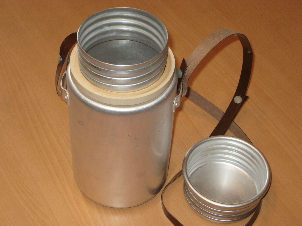
Communication between crew members was facilitated by the their headsets and laryngophones which were connected to the TPU-47 intercom system. The components of the intercom system can be seen on the wall of the turret at the left side of the photo below. The tank in the photo below does not have a radio. The turret traverse lock can also be seen attached to the turret ring, and the metal loops for personal stowage can be seen on the wall of the hull at the bottom of the photo. Each crew member in the T-54 was allotted some space of personal equipment and each crew member was provided with a two-liter aluminium bottle which would be stowed in a special holder near their respective stations. Two clips for stowing two rounds of ammunition can also be seen at the bottom right corner of the photo.

CUPOLAS
Following the precedent set by the T-34-85 and T-44, it was quite natural that the T-54 series would also have this essential design feature. Every variant of the T-54 had a rotating commander's cupola mounted on a separate cast substructure that is bolted onto the turret and multiple cupola designs were implemented throughout the evolution of the tank, ending with the introduction of the T-54A in 1954.T-54 obr. 1947


On the T-54 obr. 1947, the commander's cupola protruded very slightly from the turret roof and the roof of the cupola is almost completely flat as shown in the two photos above, taken from the Net-Maquettes scale modelers' website. There was a single MK-4S periscope (also known as a Gundlach periscope) installed centrally on the cupola roof, supplemented by two viewing prisms that were slightly offset to the left and right. The hatch opens forward and can be locked in an upright position to provide frontal protection for the commander. As one would expect, there was a rubber lining on the underside of the hatch to protect the commander's head. This layout was borrowed from the commander's cupola of the T-44, which in turn was taken directly from the T-34-85, but unlike this older design, the cupola of the T-54 obr. 1947 had a much lower profile and omitted direct vision devices entirely in order to enhance the protection of the commander and reduce the overall height of the tank. However, even though it was certainly an improvement in terms of protection, the T-54 obr. 1947 cupola was not a comprehensive upgrade as it suffered from reduced visibility. Keeping its drawbacks in mind, the cupola of the T-34-85 could at least ensure all-round visibility with five viewing slits arranged around the fixed cupola at equidistant intervals to supplement the single MK-4 periscope in the rotating cupola roof. The photo on the left below shows the cupola of a T-34-85 as seen from below, and the photo on the right shows the cupola of a T-54 obr. 1947 from a similar perspective (photo from the urban3r website).


Each viewing prism in the T-54 obr. 1947 cupola offered a horizontal field of view of 80 degrees and the full viewing arc from the cupola to the front of the turret was only around 100 degrees. In truth, the full viewing arc could have been wider but the commander's view to the right was partly blocked by the ventilation dome on the turret roof. With just three viewing devices available, the commander was forced to rotate his cupola in order to look towards the side and rear of the turret, but the ability to rotate the cupola does not completely solve the issue of reduced all-round visibility as it would take more time for the commander to scan his surroundings and the commander would not be able to notice his surroundings through his peripheral vision. When not in use, armoured covers could be closed to protect the windows of the fixed viewing prisms from gunfire.

The central MK-4S periscope was similar to the other two viewing prisms in that it gave an unmagnified view, but it was adjustable in the vertical axis. Unlike the MK-4 periscope in the T-34-85 or T-44 cupola, it was not possible to look backwards from the periscope by using its reverse view feature due to the non-rotating mount and the armoured hood around the periscope head. This distinguishes the MK-4S variant from the original MK-4. The rear view feature of the MK-4 could be used by pulling down a sliding glass prism over the eyepiece window and then turning the periscope to face the rear.

The MK-4S was obsolete as a primary observation device as it did not provide magnified vision. This limited the commander's viewing range and restricted his ability to conduct fire correction for the gunner. Beginning in 1948, the MK-4S periscope was replaced by the TPK-1 fire correction periscope.
MK-4S
The MK-4S differed from the basic MK-4 by not having a rotating mount with an armoured collar and tin hood.

The MK-4 was a copy of the British AFV Periscope No.1 Mk.1, also known as the Vickers Mk. 4 periscope, which was actually the Polish Gundlach periscope produced under licence. The Soviet designation of MK-4 was taken directly from the Vickers designation, but of course, the Soviet government did not deem it necessary to pay licencing fees for using the design. However, Soviet engineers introduced a handful of improvements over the original design such as simplifying the overly complex handle and modifying the mounting flange to include a rubber seal. As such, the MK-4 was simpler to produce, more durable, and did not leak when it rained. Interestingly enough, the MK-4 was compatible with the No.1 periscope mounting point on British tanks like the Churchill and Cromwell.

The periscope can be elevated by 18 degrees and depressed by -12 degrees for a total elevation range of 30 degrees, but to have an all-round view, the T-54 obr. 1947 commander must rotate his entire cupola as the periscope is fixed in traverse. As the MK-4S is a unity periscope with no magnifying power, the early T-54 obr. 1947 suffers from a bad case of short sightedness.
According to Soviet studies (supported by foreign studies), an optical device with no magnification would allow the gunner to see a tank from a maximum distance of 1.0-1.5 kilometers. This is corroborated by actual combat experience during WWII which showed that users could identify tanks up to a distance of 1,000-1,200 meters. This is the same as viewing with the naked eye. Although this seems adequate, it is too limited to permit the commander to perform fire corrections for the gunner and it does not allow the commander to differentiate between different tank models as he simply cannot discern such details. This was sufficient at the time due to the rather short median tank engagement distances during the war, but it was no longer enough in the postwar era. The inadequacy of the MK-4S meant that it was only ever a stopgap solution before the TPK-1 was ready for production.

The TPK-1 periscope began development in the first half of 1944, but it was only ready for mass production after the conclusion of the war and it first entered service in 1948. The TPK-1 was completely interchangeable with the MK-4S as they both shared the same mount, so it was easy to introduce the TPK-1 to tanks that were originally equipped with the older type.
The TPK-1 was a notable improvement over the old MK-4S for observation at longer distances as it provided a 2.5x magnification power. The requirement set by the GBTU (Directorate of Armoured Forces) was for an effective viewing range of 1,500 meters and easier fire correction than from the venerable MK-4S, and the TPK-1 periscope met those requirements. An internal mirror could be unfolded above the binocular optics to display an unmagnified image through the viewing window above the binocular eyepieces, thus duplicating the function of the MK-4S. This gave the commander the luxury of both a wide-vision 1x periscope and a 2.5x magnified optic in the same device. The photo below shows a T-54 commander looking through this viewing window.

Although the modest 2.5x magnification of the device is totally inadequate for long range observation in a modern context, studies and records showed that tank combat distances during WWII generally did not exceed a kilometer. In fact, combat data from the Aberdeen Proving Ground showed that 80% of all encounters between tanks and other tanks or anti-tank weapons occurred at a distance of less than 1,000 yards. There were practically no encounters beyond 2,000 yards. From this perspective, the device is quite adequate, although not entirely ideal since a higher magnification would certainly have been appreciated for easier target identification at the upper boundaries of expected combat distances. For long range observation, the commander would have to rely more on his personal 8x30 field binoculars, which were usually of superb quality, as most examples of this line of binoculars made in the USSR were built using tooling plundered from the German Zeiss-Jena factory at the climax of WWII.
What a pair of 8x30 field binoculars doesn't have, though, is a stadiametric rangefinder. The stadia markings in the TPK-1 viewfinder allowed the commander to rapidly estimate the distance to a typical tank-type target with a height of 2.7 meters, and the additional markings allowed him to estimate lead for the target to a limited extent. These modest features were not insignificant, considering the fact that the MK-4S periscope lacked any mil markings whatsoever and did not permit even basic range estimations.

That, however, is not the biggest breakthrough from this new device. The most significant feature of the TPK-1 is its ability to designate targets for the gunner. This is done by simply aiming the device at the target and pressing the left thumb button. An electric signal is sent to the turret traverse motor, and by referring to a deflection sensor attached to the cupola ring, the turret is automatically rotated to meet the target. The deflection sensor detects if the cupola is turned away from the 12 o'clock position relative to the turret but does not record the actual azimuth of the cupola. If the sensor detects that the cupola is rotated counter-clockwise relative to the turret, the turret will be rotated counter-clockwise and vice versa. Once the commander has designated a target, the turret will turn until the cupola is once again at the 12 o'clock position relative to the turret - indicating that the turret is facing the same direction as the commander - and the turret traverse motor is halted.
Turret traverse is only conducted at maximum speed in order to minimize the reaction time of the system. As the gun elevation mechanism lacked power controls, it was still up to the gunner to adjust in elevation. The commander does not need to hold the button to slew the turret all the way to the target. A single click will do. Holding the button will prompt the turret to slew to meet the target and remain slaved to the periscope, thus allowing the commander to commandeer the turret as its movement would then depend on the commander rotating his cupola. Small corrections made by rotating the cupola slightly will not cause the turret to jerk onto the new aiming point even though turret traverse is done at maximum speed by default. This is because the traverse motor will need time to accelerate the turret to its maximum speed (due to inertia), so the turret will turn quite slowly if the arc of rotation is very small. The effect is that the commander can guide the gunner onto target quite gently if he turns the cupola slowly enough.
This arrangement can be described as a hunter-killer system, making the T-54 the first tank ever to implement such a system, followed by the British Conqueror heavy tank in 1955. The commander of a T-54 is not provided with duplicated firing controls so he cannot override the gunner completely, but this has little bearing on the definition of a hunter killer system. During the early 1950's, the TPK-1 periscope and the associated fire control modifications was retrofitted to IS-2 and IS-3 tanks to modernize them to the IS-2M and IS-3M standard, thus bringing the hunter-killer feature to the Soviet Army's workhorse heavy tanks as well.

To solve the visibility issues of the earlier cupola design, the T-54 obr. 1949 cupola had five viewing prisms of a new design arranged around the circumference of the cupola roof, thus guaranteeing that the commander could easily survey his surroundings without needing to rotate the cupola. Including the central TPK-1 periscope, there were six viewing devices in total, putting it directly on par with the T-34-85 or T-44 cupola design. Moreover, the viewing prisms also had a larger horizontal field of view of 86 degrees instead of 80 degrees.
However, the diameter of the cupola was not decreased and there was no additional space left for the viewing prisms around the rear half of the cupola, so the commander's hatch was shrunk to accommodate them. The exact dimensions of the hatch are currently not available, but needless to say, the resulting design was far from optimal. The other details of the cupola design such as the periscope mount and the hatch locking mechanism remained largely identical.
The photos below, taken by Vladimir Yakubov, shows a T-54 obr. 1949 housed in the Kubinka Armor Museum. The positions of the viewing prisms on the sides and rear of the cupola can be seen.


Strangely enough, the cupola is shown to be slightly tilted in some drawings, but not in others. If it was really tilted, the small angle probably did not massively affect the balance of the cupola to make it harder to rotate, but it most likely had a minor negative effect on the commander's view of the battlefield through the periscopes.


The cupola design was changed yet again in the T-54 obr. 1951 model to correct the drawbacks of the earlier design. The viewing prisms used in all of the previous T-54 models were replaced with periscopes, and the cupola layout returned to the same style as the T-54 obr. 1947. The height of the cupola was increased, and the commander's hatch gained a dome shape. This greatly increased the amount of headroom in his station and also made it possible to embed the side and rear view periscopes in the hatch itself. By relocating all of the five general vision periscopes to the rotating cupola with three embedded into the hatch itself, it was possible to increase the size of the hatch back to the same dimensions as the T-54 obr. 1947 without increasing the size of the cupola or compromising on the commander's circular visibility. Furthermore, it was level unlike the cupola of the T-54 obr. 1949.
The increased height of the cupola had the beneficial side effect of giving the periscopes more clearance from the turret roof, giving the commander a better view over the loader's cupola and the ventilation dome in front of it. This improved the commander's all-round visibility towards the right side of the turret, but came at the expense of making the cupola a slightly more prominent target.
TPK-1
The TPK-1 periscope began development in the first half of 1944, but it was only ready for mass production after the conclusion of the war and it first entered service in 1948. The TPK-1 was completely interchangeable with the MK-4S as they both shared the same mount, so it was easy to introduce the TPK-1 to tanks that were originally equipped with the older type.
The TPK-1 was a notable improvement over the old MK-4S for observation at longer distances as it provided a 2.5x magnification power. The requirement set by the GBTU (Directorate of Armoured Forces) was for an effective viewing range of 1,500 meters and easier fire correction than from the venerable MK-4S, and the TPK-1 periscope met those requirements. An internal mirror could be unfolded above the binocular optics to display an unmagnified image through the viewing window above the binocular eyepieces, thus duplicating the function of the MK-4S. This gave the commander the luxury of both a wide-vision 1x periscope and a 2.5x magnified optic in the same device. The photo below shows a T-54 commander looking through this viewing window.
Although the modest 2.5x magnification of the device is totally inadequate for long range observation in a modern context, studies and records showed that tank combat distances during WWII generally did not exceed a kilometer. In fact, combat data from the Aberdeen Proving Ground showed that 80% of all encounters between tanks and other tanks or anti-tank weapons occurred at a distance of less than 1,000 yards. There were practically no encounters beyond 2,000 yards. From this perspective, the device is quite adequate, although not entirely ideal since a higher magnification would certainly have been appreciated for easier target identification at the upper boundaries of expected combat distances. For long range observation, the commander would have to rely more on his personal 8x30 field binoculars, which were usually of superb quality, as most examples of this line of binoculars made in the USSR were built using tooling plundered from the German Zeiss-Jena factory at the climax of WWII.
What a pair of 8x30 field binoculars doesn't have, though, is a stadiametric rangefinder. The stadia markings in the TPK-1 viewfinder allowed the commander to rapidly estimate the distance to a typical tank-type target with a height of 2.7 meters, and the additional markings allowed him to estimate lead for the target to a limited extent. These modest features were not insignificant, considering the fact that the MK-4S periscope lacked any mil markings whatsoever and did not permit even basic range estimations.

That, however, is not the biggest breakthrough from this new device. The most significant feature of the TPK-1 is its ability to designate targets for the gunner. This is done by simply aiming the device at the target and pressing the left thumb button. An electric signal is sent to the turret traverse motor, and by referring to a deflection sensor attached to the cupola ring, the turret is automatically rotated to meet the target. The deflection sensor detects if the cupola is turned away from the 12 o'clock position relative to the turret but does not record the actual azimuth of the cupola. If the sensor detects that the cupola is rotated counter-clockwise relative to the turret, the turret will be rotated counter-clockwise and vice versa. Once the commander has designated a target, the turret will turn until the cupola is once again at the 12 o'clock position relative to the turret - indicating that the turret is facing the same direction as the commander - and the turret traverse motor is halted.
Turret traverse is only conducted at maximum speed in order to minimize the reaction time of the system. As the gun elevation mechanism lacked power controls, it was still up to the gunner to adjust in elevation. The commander does not need to hold the button to slew the turret all the way to the target. A single click will do. Holding the button will prompt the turret to slew to meet the target and remain slaved to the periscope, thus allowing the commander to commandeer the turret as its movement would then depend on the commander rotating his cupola. Small corrections made by rotating the cupola slightly will not cause the turret to jerk onto the new aiming point even though turret traverse is done at maximum speed by default. This is because the traverse motor will need time to accelerate the turret to its maximum speed (due to inertia), so the turret will turn quite slowly if the arc of rotation is very small. The effect is that the commander can guide the gunner onto target quite gently if he turns the cupola slowly enough.
This arrangement can be described as a hunter-killer system, making the T-54 the first tank ever to implement such a system, followed by the British Conqueror heavy tank in 1955. The commander of a T-54 is not provided with duplicated firing controls so he cannot override the gunner completely, but this has little bearing on the definition of a hunter killer system. During the early 1950's, the TPK-1 periscope and the associated fire control modifications was retrofitted to IS-2 and IS-3 tanks to modernize them to the IS-2M and IS-3M standard, thus bringing the hunter-killer feature to the Soviet Army's workhorse heavy tanks as well.
T-54 obr. 1949

To solve the visibility issues of the earlier cupola design, the T-54 obr. 1949 cupola had five viewing prisms of a new design arranged around the circumference of the cupola roof, thus guaranteeing that the commander could easily survey his surroundings without needing to rotate the cupola. Including the central TPK-1 periscope, there were six viewing devices in total, putting it directly on par with the T-34-85 or T-44 cupola design. Moreover, the viewing prisms also had a larger horizontal field of view of 86 degrees instead of 80 degrees.
However, the diameter of the cupola was not decreased and there was no additional space left for the viewing prisms around the rear half of the cupola, so the commander's hatch was shrunk to accommodate them. The exact dimensions of the hatch are currently not available, but needless to say, the resulting design was far from optimal. The other details of the cupola design such as the periscope mount and the hatch locking mechanism remained largely identical.
The photos below, taken by Vladimir Yakubov, shows a T-54 obr. 1949 housed in the Kubinka Armor Museum. The positions of the viewing prisms on the sides and rear of the cupola can be seen.


Strangely enough, the cupola is shown to be slightly tilted in some drawings, but not in others. If it was really tilted, the small angle probably did not massively affect the balance of the cupola to make it harder to rotate, but it most likely had a minor negative effect on the commander's view of the battlefield through the periscopes.

T-54 obr. 1951

The cupola design was changed yet again in the T-54 obr. 1951 model to correct the drawbacks of the earlier design. The viewing prisms used in all of the previous T-54 models were replaced with periscopes, and the cupola layout returned to the same style as the T-54 obr. 1947. The height of the cupola was increased, and the commander's hatch gained a dome shape. This greatly increased the amount of headroom in his station and also made it possible to embed the side and rear view periscopes in the hatch itself. By relocating all of the five general vision periscopes to the rotating cupola with three embedded into the hatch itself, it was possible to increase the size of the hatch back to the same dimensions as the T-54 obr. 1947 without increasing the size of the cupola or compromising on the commander's circular visibility. Furthermore, it was level unlike the cupola of the T-54 obr. 1949.
The increased height of the cupola had the beneficial side effect of giving the periscopes more clearance from the turret roof, giving the commander a better view over the loader's cupola and the ventilation dome in front of it. This improved the commander's all-round visibility towards the right side of the turret, but came at the expense of making the cupola a slightly more prominent target.

One drawback of this periscope layout was that the rear view periscope prevented the hatch from being opened unless it was removed. This made it impossible to open the hatch from outside the tank if the periscope was installed. If the commander was already at his station, the need to remove the periscope was an obstacle that complicated a speedy exit through the hatch. There was no real solution for bypassing this issue other than to keep the rear view periscope permanently stowed away.
T-54A (and later)
When the T-54A was created, it was given a new cupola design that remained the final variation to be found on any serial T-54 model and was later used on the T-54B and T-55 series, before also being adopted for the T-62 series and then becoming the template for the commander's cupola of the T-64, T-72 and T-80 main battle tanks.
The cupola was largely identical to the T-54 obr. 1951 design with modifications made to accommodate the new "Uzor" night vision system consisting of an OU-3 infrared spotlight and the TKN-1 night vision periscope. The modifications included the addition of a mounting point for the OU-3 spotlight above the central periscope hood, a hole in the cupola roof for the actuating rod that joins the TKN-1 periscope to the OU-3 spotlight, and the removal of the rear view periscope in the hatch due to the inconvenience it caused.


As the photo below shows, the rear periscope in the hatch that could be found on the T-54 obr. 1951 was replaced with a simple steel handlebar.

The T-54A retained the TPK-1 periscope for fire correction and general observation, but later tanks like the T-54B had the improved TPKUB periscope and later, the TPKU-2B.
The bolt-on substructure on which the cupola is mounted has a minimum internal race ring diameter of 570mm and the substructure itself has an external diameter of 624mm. The rotating cupola itself fits inside this substructure. As shown in the drawing, the substructure is horizontally slanted by 17 degrees to offset the slope of the T-54 turret roof. This creates a level plane for the cupola to be mounted on, which is important because a tilted cupola makes it extremely difficult for the commander to use the viewing devices and the cupola itself would require more force to rotate.

The cupola and the cupola hatch are shown in the two drawings below. The hatch itself has a total length and total width of 497mm and 670mm respectively, but the actual opening in the cupola through which the commander can ingress and egress is much smaller as the length of the hatch includes the hinge where it attaches to the cupola and the edge where it overlaps with the lip of the cupola race ring. The actual size of the opening is only approximately 400mm long and the width is 570mm as indicated by the minimum internal diameter of the cupola substructure.
The height of the exposed cupola excluding the race ring which fits into the cupola substructure is 131mm and the entire cupola is thickly armoured and sloped.


TPKUB, TPKU-2B
The commander of an early issue T-54B was equipped with the TPKUB binocular periscope. This was a binocular magnified periscope like the TPK-1, but it lacked the wide vision feature of its predecessor. The TPKUB had a single left handle for the commander to grasp, but the much more common TPKU-2B model that came later had two handles. The left handle on both models contains the target designation button for the tank's hunter-killer system. The new periscope was a step forward over the TPK-1 in the observation range thanks to the increased magnification. Many older T-54 models were retrofitted with the TPKU-2B to bring it up to the same level of technology as the T-54B.


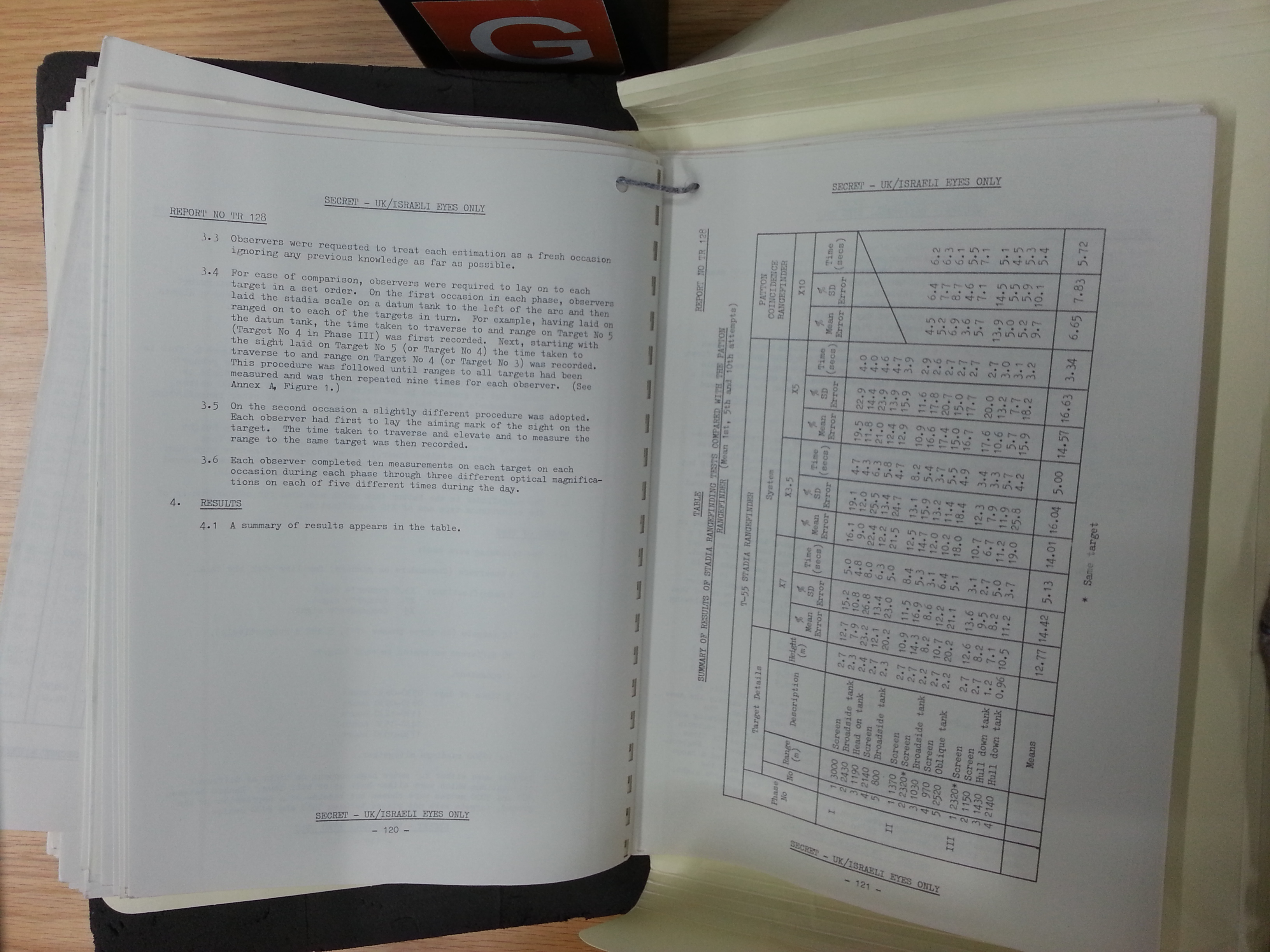
The sight has two adjustable magnification settings of either 1x or 5x. Under 1x magnification, the field of view from the sight is 17.5 degrees. This is reduced to 7.5 degrees under 5x magnification. The general layout of the viewfinder and the reticle is the same as in previous periscopes. The viewing distance is improved by the higher magnification factor, but the rangefinding capabilities of the periscope are probably not improved at all. A British-Israeli report made available on the tankandafvnews website reveals some interesting information on the precision of rangefinding through the TPKU-2B: from the table in page 121 (page 64 of the photo album), the mean error in ranging tank-shaped screens, broadside tanks, oblique tanks (meaning: angled hull) and head-on tanks is 14.57%. The results of an analysis of the data were somewhat counter-intuitive.
Page 122 of the report (page 65 of the photo album) mentions that the precision of rangefinding against hull-down tanks was surprisingly unaffected by the fact that half of the target was out of sight. The report does not say why, but we can conjecture that it is because stadia rangefinding is partly technique and partly guesswork. The full report on tankandafvnews is worth reading in its entirety as it is very enlightening.
The tests show that the commander is able to range the target in an average time of 3.3 seconds, and this section of the report concludes that the short time required to obtain a range estimate is unobtrusive to the loading and laying of the gun. This means that by the time the gunner has visually acquired the target, he will already know the range, and can open fire without delay.
Like the TPK-1, the TPKU-2B has a target designation function. The target designation system is a rather simple one; A direction sensor is installed in the 5 o'clock position of the cupola. The direction sensor consists of a roller placed in permanent contact with the cupola race ring, a cam attached to the roller and two switches. The roller is recessed into a notch in the cupola race ring when the cupola is turned to the 0 o'clock position relative to the turret. When the cupola is turned to the right, the motion of the cupola race ring dislodges the roller from the notch and causes the roller to be deflected to the left by friction. The cam attached to the roller also rotates left, causing it to touch the switch on the right (see diagram on the top right, below). The right switch triggers the turret rotation motor to turn the turret to the right until the roller returns to the notch, which would mean that the gun is now facing the same direction as the commander's cupola. The same mechanism is repeated in reverse when the cupola turns to the left. Since the direction sensor is composed of two switches which can only be either on or off, the command to initiate turret rotation is binary. This means that the turret is either turning, or it is not. For that reason, the turret always rotates at maximum speed when the target designation system is activated.

The binary system also does not allow the commander to precisely lay the gun on target, because precision gun laying is done at the minimum turret rotation speed, which would be 0.07 degrees per second in the case of the T-55. Potentiometers would be needed in order to have a variable speed of turret rotation. However, as mentioned before, small corrections made by rotating the cupola slightly will not cause the turret to jerk onto the new aiming point, even though turret traverse is done at maximum speed by default. This is because the somewhat underpowered traverse motor will need time to accelerate the turret to its maximum speed. There is no vertical deflection sensor attached to the TPKU-2B periscope, so it is not possible for the commander to raise the cannon onto the target from his station.
TKN-1, TKN-1S

The TKN-1 periscope was a monocular night vision surveillance device, and it was the first serially produced device of its kind to be used in the Soviet Army. As the TPK-1 and TPKU-2B periscopes lacked any provisions for effective nighttime use, it was necessary to swap it out for the TKN-1 before commencing night operations. The TKN-1 was introduced in 1954, and was used on the T-54A, T-54B, and later on in the T-55 as the TKN-1S.


TKN-1 has a fixed 2.75x magnification. This is insufficient for long range observation, but due to the short range provided by the TKN-1. The angular field of vision is 10 degrees. TKN-1 fits in the same slot as the TPKU-2B. Older model T-54s can also use TKN-1, but only if they have been modernized to include the BT-2-26 power supply system.

The TKN-1 required a source of near infrared light for illumination. This is provided by an OU-3 infrared spotlight that is directed in elevation by a mechanical rod linked to the TKN-1. When the periscope is adjusted to look up and down, the spotlight is rotated around its hinge to follow the commander's line of sight.

The infrared light from the spotlight illuminates the target, and the reflected light entering the objective lens of the periscope is then amplified by an image intensifier tube operating on 17 kV. The power cable connecting the periscope to the tank's electrical system can be seen on the left side of the periscope, as seen in the photos below (Photo credit to ancientpieces from ebay). The power cable supplies power to the transformer housed in the box on top of the eyepiece, and another cable runs from the transformer to the image intensifier installed inside the optic.


Using the TKN-1 with the illumination from the OU-3 will enable the commander to identify tank-type targets at a distance of only 250-300 meters. Due to the short viewing distance, the TKN-1 is generally only suitable for spotting enemy tanks that are also using active infrared illumination, for following the fall of tracers, for observing the impact of shots and for spotting the muzzle flash of enemy tanks. The view through the eyepiece of the TKN-1S is shown in the two photos below (image credit to kmshik from the GAZ 69 forums).


Like the TPKU-2B, the TKN-1 can be used to designate targets by pressing the left thumb button. On the right handgrip is a thumb button to activate the OU-3 infrared searchlight on the cupola. It is not only possible for the sight to be turned to the active infrared imaging mode without turning on the searchlight, it is highly recommended. If enemy tanks have infrared searchlights as well, then the commander will be able to spot them easily without needing to turn on his own, thus remaining hidden. Use of infrared illumination is usually only tactically viable with good coordination and fire control, or when enemy tanks have absolutely no night vision equipment at all.
GUNNER'S STATION
The T-54 gunner sat directly in front of the commander. The gunner's seat was mounted to a frame bolted to the turret wall to the left of the gun cradle and he was provided with a foot rest. His seat could be folded up and to the right and locked flush against the recoil guard of the D-10T gun to permit freer access to the hull, particularly if the gunner wants to crawl out through the escape hatch behind the driver's seat.
The gunner could determine the orientation of the turret in azimuth by referring to an azimuth ring marked on the turret ring. This was quite typical for many tanks of that era, although some already had more sophisticated clock-type azimuth indicator mechanisms that offered higher measuring precision.
In all T-54 models up to the T-54A, the gunner was provided with a single MK-4 periscope for general surveillance. It was installed in the turret roof and was positioned to the left of the telescopic primary sight as shown in the photo above. As mentioned before, the MK-4 has a rear view feature, can be rotated independently, and can be elevated by 18 degrees and depressed by -12 degrees. For T-54 gunners, the main benefit of having the MK-4 was the fact that it had a fixed handle and could be elevated and depressed independently of the turret, so when the tank moved over rough ground, the gunner could grasp the handle of the MK-4 firmly and press his forehead against the brow pad to keep a relatively stable view of the terrain. Keeping in mind that early T-54 models lacked a gun stabilizer, this provided the gunner with the ability to continue contributing to the surveillance capabilities of the tank to some degree while most other tanks did not.


However, the independent rotation and the rear view capability of the MK-4 were not useful for the gunner because of the location of the periscope. The commander's cupola obstructed the gunner's view to the rear, the telescopic primary sight made it difficult for the gunner to look to the left, and the turret wall itself made it difficult to look to the right. As such, the gunner's field of view was not as good as the design of the MK-4 itself implied.

Nevertheless, the MK-4 gave the gunner unusually good situational awareness compared to many other tanks, but in practice, it was somewhat flawed. After numerous field exercises were conducted by units equipped with the T-54 in the late 40's and early 1950's, it was found out that the MK-4 could not be used for too long when the tank was driving over rough ground as the pitching of the tank could give the gunner motion sickness. It was far more profitable to focus on the operating the main sight instead and leave the MK-4 be until it was needed, like when the tank enters a turret defilade position. The gunner would then use the periscope to observe targets without needing the turret to be exposed and without needing to turn the turret, since the MK-4 could rotate independently.
On the T-54B model, the MK .4 was replaced by the TPN-1 night vision sight, so its role was taken over by a single fixed forward-facing periscope installed above the TSh2-22 primary sight. This configuration was kept in the T-55 and T-55A. As a result of the loss in the ability to independently rotate the periscope, the gunner's vision deteriorated slightly. However, the T-54A and T-54B already featured gun stabilizers so the gunner had a stable view of the battlefield through his primary sight when the tank was in motion, so the gunner's ability to scan for targets did not decline but instead increased considerably, and the essential ability to scan for targets when in a turret defilade position was maintained. Overall, the gunner was well-equipped for his duties and the T-54 must be considered excellent in this regard.
Laying the gun in elevation was done using a spirit level affixed next to the gun, and laying the gun in the horizontal plane was facilitated by a turret azimuth indicator, as seen below. The indicator works like a clock with two hands. The indicator can be seen next to the manual turret traverse handwheel in T-54 models beginning from the T-54A (1954).


The azimuth indicator measures the orientation of the turret according to the Soviet mil definition where a full circle is divided into 6,000 mils and the azimuth reading is divided into tens and hundreds with the 3,000 mil position (30-00) being the 12 o'clock position. For example, if the turret is oriented 180 mils to the left, it is in the 28-20 position, and if the turret is oriented 340 mils to the right, then it is in the 33-40 position. The 00-00 and 60-00 positions are equivalent.
The ventilation porthole in the commander's cupola allows a panoramic periscope for indirect fire to be installed.
TSh-20

The TSh-20 was an articulated telescopic sight. Most telescopic sights from the WWII era including the TMFD-7 and TOD sights of the T-34 were fixed to the cannon so that if the cannon elevated, the telescope went up and down along with it. This meant that the eyepiece would never be in the same spot as the gunner fiddled around trying to get a firing solution for his target. In the TSh-20, the telescopic aperture is joined to the telescope body with a hinge, optically connected by cleverly placed mirrors. With an articulated telescopic sight, the eyepiece and the main telescope body could stay fixed while only the aperture moved. This eliminated the problem of gunner fatigue and improved firing accuracy, as the gunner will always maintain optimum eye relief. This arrangement was first used in the Soviet weapons industry in the TSh-16, which was installed in the T-34-85.
The T-34's PT-4-7 sight (below, left) featured a similar system of range adjustment. The horizontal line can be moved while the vertical line remains static, unless lead is applied. The intersection point between the two lines forms the crosshair. As the horizontal line is moved down the range scales to the appropriate distance to the target for a given ammunition type, the crosshair is moved down by the same amount.


The newer TSh-16 (above, right) offered an improved viewfinder arrangement. The viewfinders on the TSh series of telescopic sights generally have a better layout as all of the "clutter" is concentrated in the top half of the sight picture where there is nothing but sky. This means that the gunner's view of everything from the ground up to the horizon is perfect, but his view of the sky is not, which is obviously not important. Insufficient magnification power of the TSh-16 aside (only 2.5x), the design of the viewfinder was considered sound, so it was carried over to the TSh-20.
One excellent feature of the TSh-20 sight is the large rubber brow pad. It is large enough to fit around the gunner's forehead and temples - even if he is wearing his helmet - and stiff enough to hold his head in place, so that even if the gunner's body is rocking about, his head will be held firm and his eyes can be glued onto the eyepiece. This is a traditional feature of almost all gun sights on Soviet and Russian tanks, including later sights present on the T-54, which we will discuss later, all the way up to the Sosna-U on the latest T-90MS.
TSh-20 offers a fixed 4x magnification with a 16° field of view. This is horrible by modern standards, but arguably within acceptable limits for a 1945 product. For example, the M71C for the Pershing had a fixed 5x magnification with a 13° field of view. The extra wide vision arc offered by the TSh-20 enabled the gunner to survey for targets at short to medium distances more easily, but severely handicapped the long range viability of the tank. Whether high magnification was necessary during that particular stage of global tank evolution is not too clear. U.S research showed that the average tank duel in the Korean war occurred at an average distance of only 450 yards (411 m) due to the abundance of natural obstacles and obscurants. In addition to that, Soviet experience and research during WWII showed that almost all tank duels fought by Red Army tanks occurred under 1 kilometer in distance. With heavy, hours-long artillery barrages usually preceding breakthrough assaults, smoke and dust in the air often reduced tank engagement distances to just a few hundred meters, with many tanks only meeting each other at "knife fight" distances (also making head-on collisions, accidental and non-accidental, surprisingly common).
If the T-54 obr. 1947 came early enough to fight in WWII, or if its sequel was conducted in much the same way, then perhaps TSh-20 is good enough. However, it was impossible not to recognize that tank warfare was evolving and that the requirements for sight magnification had become more demanding.
TSh2-22, TSh2B-22

TSh2-22 was introduced with the T-54 obr. 1949. Continual field trials of the T-54 obr. 1947 throughout 1948 had shown that one of the chief complaints was the limited magnification of the TSh-20. Consequently, TSh2-22 features variable magnification settings of 3.5x and 7x. By implementing variable magnification in the gun sight, the gunner could enjoy both wide vision and high power magnification, though obviously not at the same time. For an even wider field of view, the MK-4 rotating periscope would more than suffice. The TSh2B-22 sight was a modification of the basic model with new design features that gave it compatibility with the STP-1 gun stabilizer of the T-54A respectively.
TSh2-22 is directly comparable to the Centurion's No.1 sight which had a variable magnification of 1x or 6x and the M47 Patton's M20 sight, which also had a variable magnification of 1x or 6x. The M20 sight was shared by the M48 as well.
There are multiple variations of the TSh2-22 viewfinder. An early versions (a) has four scales; three for main gun rounds and one for the coaxial machine gun. Listed from left to right, they are: HE-Frag with a full charge (53-UOF-412), APBC (53-UBR-412B), HE with a reduced charge (53-UOF-412U) and finally, the coaxial machine gun. A late version (b) has just two scales for main gun ammunition: HE with a full charge and APBC, plus one for the coaxial machine gun.

Moreover, the later version included additional horizontal lead markings and a stadia rangefinder scale to allow the gunner to quickly measure the range in case the commander is preoccupied or if the tank is running in a degraded state with a 3-man crew. It allows the gunner to switch from battlesight gunnery to precision gunnery, which is necessary to ensure a reasonable probability of hit on targets that are beyond the point blank range of the tank's 100mm armour-piercing ammunition. The stadia rangefinder markings start at 1,220 meters, which is the point blank range for the BR-412B and BR-412D rounds against a target with a height of 2.7 meters.

Another difference is the removal of the range markings on the vertical line below the center chevron. These range markings are meant to be convenient aiming points for common combat distances using APBC shells to aid the gunner if he decides to use the bracketing gunnery technique to engage a target. It is reasonable to assume that with the addition of a stadia rangefinder scale, it became superfluous as it would be slower, less accurate, and more wasteful of ammunition compared to stadia rangefinding. At least, this was the case in other contemporary sights. Multiple viewfinder configurations with various combinations of markings existed and small changes were implemented over time, making it rather difficult to classify the TSh2-22 this way. The markings were etched on a special viewfinder glass disc that could be removed relatively easily and replaced with updated markings when new ammunition became available.


The sight is ordinarily zeroed to a distance of 1,200 meters or more. The drawing below depicts a method of zeroing the sight in field conditions by using a landmark.

By displaying all of the range scales in the viewfinder and not on an external dial, the gunner can conduct the entire target acquisition procedure without removing himself from the sight and losing visual contact with the target. This problem was solved in the Centurion in a rather creative way; a mirror was placed in front of the gunner's left eye at such an angle that the gunner could see the range drum with his left eye as he adjusted it, and then - by just moving his eyes - return to the sight and resume targeting.
To use the rangefinder, the gunner only needs to bracket the target tank between the stadia lines and read the figure corresponding to the height of the target, and then turn the range adjustment dial until the horizontal line is on the correct range scale mark for the desired ammunition type. It is also possible for the gunner to use the multitude of chevrons and lines that form the reticle of the sight viewfinder and combine them with his own memorized information of tank widths and lengths to obtain a range estimate.
The sight aperture port cut into the turret was protected by a pane of glass. This was merely a thin barrier to prevent external debris and water from entering the turret through the aperture. It had no ballistic protection whatsoever.


While Soviet-built tanks had a stadium-shaped glass cover that was affixed to a raised lip that is shaped accordingly, Polish-built T-54 tanks used an oval-shaped glass cover. This can be used to identify the origin of the tank regardless of its markings.


TSh2B-32 was first implemented in the T-54B. The sight was practically identical to the previous articulated telescopic sights with the main difference being that it was designed to connect to the new STP-2 gun stabilizer. This sight continued to be used in the T-55 series as the fire control system did not change. The configuration of the viewfinder markings follows the latest variant of the TSh2B-22. As shown in the photo below, there were range scales for HE-Frag with a full charge, APCBC, HEAT and the coaxial machine gun. Additionally, the markings for HE ammunition with a reduced charge were permanently removed as this type of ammunition had become obsolete.

In January 1965, the TSh2B-32P was installed in the T-54B and T-55. The only difference between it and the TSh2B-32 is the new range scale for 3UBM6 APDS ammunition. The "P" in "TSh2B-32P" stands for "subcaliber". Tanks that had the TSh2B-32 equipped were modified by swapping out the viewfinder glass disc with a new disc with the additional markings to transform them into the TSh2B-32P.


Besides the range scale for subcaliber rounds, there are no other notable differences. It is worth noting that the scale for subcaliber rounds can be used for both APDS (3BM8) rounds and APFSDS (3BM19, 3BM20, 3BM25) rounds due to the very similar ballistic trajectories of both types of ammunition and the low precision of this type of range scale. For instance, the 3BM20 APFSDS shell had a point blank range of 1,690 meters against a target with a height of two meters and a point blank range of 2,040 meters against a target with a height of three meters while the 3BM8 APDS shell had a point blank range of 1,680 meters against a target with a height of two meters and a point blank range of 2,020 meters against a target with a height of three meters. In realistic conditions, this small difference is practically imperceptible.


In the year 1957, the T-54 entered its tenth year of formal service in the Soviet Army and also the tenth year of its continuous evolution, becoming the T-54B. The T-54B became capable of night fighting with the installation of the TPN-1-22-11 active infrared imaging sight and the accompanying L-2 "Luna" infrared spotlight. Although the performance of the night vision system is far from impressive by modern standards, it was a modern product for its time and the inclusion of a night vision sighting system in the T-54B together with a night vision TKN-1 optic for the commander gave it a distinct edge over the contemporary M48A2 which lacked any form of night vision sighting equipment whatsoever. Only the M60A1 from 1962 was equipped with a night vision sight (M32) and a night vision optic for the commander (M36). The armoured hood for the TPN-1 night sight on the T-54B can be seen in the photo below in front of the commander's cupola.

TPN-1-22-11 can operate in either the active infrared imaging mode or the passive light intensification mode. In the active infrared imaging mode, the infrared light supplied by the L-2 "Luna" spotlight mounted coaxially to the main gun is visible through the sight, allowing the gunner to identify a tank-type target at a maximum distance of 750-800 meters. This was quite good for night vision equipment from the 50's. The L-2 "Luna" spotlight uses an incandescent bulb and consumes only 200 W, which is quite weak for a spotlight. In the passive mode, the sight employs a 1st Generation light intensifier tube to amplify ambient light, providing a nominal maximum identification distance of 400 meters for a tank-type target under lighting conditions of no less than 0.005 lux. The sight has an adjustable sensitivity to allow the gunner to obtain the best image under different lighting conditions.

TPN-1-22-11 has fixed 5.5x magnification, and a narrow field of view of 6 degrees. The magnification is quite reasonable for a night vision device, as the IR sight for the Chieftain only had a 3x magnification. The viewfinder is extremely simple, as you can see below. The tip of the chevron is sighted for BR-412D AP rounds for a distance of 200 m, going down to 400 m at the upper tip of the vertical reticle line below the chevron. A more comprehensive adjustment system was not included as the short range of the TPN-1-22-11 night vision system limited engagement distances to 800 meters or less anyway.

The TPN-1-22-11 has an internal lightbulb to facilitate aiming at night. It is either on or off without the option of dimming, but it can be turned on in either the day mode or the night mode as the gunner wishes. It is preferable to remain in the day mode with an illuminated reticle when operating during sunset or twilight hours.
TPN-1-22-11 is similar to the telescopic primary sight in that it is not independently stabilized. It is only connected to the main gun by a mechanical linkage as shown in the drawing below. Disregarding its night vision capabilities, the sight is mechanically and optically quite simple.

During the late 50's, nearly all T-54 obr. 1949 tanks (built and issued from 1949 to 1951) and T-54 obr. 1951 tanks (built and issued from 1952 to 1954) underwent a modernization program to improve its combat capabilities to the level of the T-54B, which was the latest iteration at the time. The technical details for the modernization of older tanks - excluding the troublesome obr. 1947 model - to the standard of the T-54B model was prepared simultaneously with the development of the T-54B itself, thus ensuring that a large part of the Soviet Army's T-54 fleet would be kept up to date at the highest available level of technology. One of the upgrades was the addition of night fighting capabilities via the installation of the TPN-1-22-11 night vision sight and the associated equipment, including the L-2 "Luna" spotlight and a new power supply system to handle the new equipment. The T-54-2 in the two photos below is an example of a tank modernized to T-54B standards. Note the counterweight at the muzzle of the cannon. This will be examined further in the article.


The addition of a night fighting capability to the vast majority of the T-54 tanks in the Soviet Army represented a significant tactical advantage, considering that the M60A1 was only being produced in relatively small numbers during the early 60's and the M48A2 modernization in 1956 did not grant the U.S Army's large fleet of M48 Patton tanks a night fighting capability. Even when the M48 gained a xenon spotlight and the M32 periscope in 1963 as part of the M48A3 upgrade, the T-54 retained an advantage because its night sight had a passive image intensifier mode that made it possible for the gunner to engage targets without turning on its infrared spotlight, whereas the enemy M48A3 and M60A1 tanks were forced to rely entirely on active IR or white light illumination.
The night vision equipment was tested in a British/Israeli assessment of the T-55, among other things. The full report is available in the Tanks and AFV News site. The relevant page of the report can be viewed here (link). According to the test, TPN-1-22-11 allowed the gunner to see:
However, the report notes that the equipment was "suspect in nature" and that too much significance should not be attached to the results. This is possible evidence that the night vision equipment was downgraded for export. It is also possible that the sight was somehow damaged or defective. The problem does not lie in insufficient illumination (200 W spotlight), as the TPN-1-22-11 was also tested using the Chieftain's 2 kW infrared spotlight, but this only marginally improved the maximum identification distance to 500 meters when used to identify a Chieftain target tank.
Another explanation is that the TPN-1-22-11 has lackluster performance simply because it is older than whatever the Chieftain uses by almost a decade, but then, why did the report mention that the equipment was "suspect in nature"?
The T-55AM deep modernization programme of 1983 involved a total overhaul of the fire control system as well as a base overhaul of the engine and other essential components.


Introduced as a complement to the Volna fire control system, TShSM-32PV is substantially more advanced than the previous telescopic sights used in the T-54 series. TShSM-32PV features a viewfinder that is very similar to the TPD-K1 in layout, especially with the removal of the range scales and its substitution with a more space efficient dial-type range indicator at the top.

The magnification of TShSM-32PV is practically identical to its predecessors; either 3.5x power magnification or 6.9x. The sight offers a field of view of 18 degrees in the low magnification setting and 9 degrees in the high magnification setting. The sight is independently stabilized in the vertical plane with a maximum accuracy of 0.3 mils, which is quite good. At 1000 m, the sight will have a maximum deviation of 0.3 meters from the point of aim.
Now that the sight is linked to an analogue ballistic computer, additional features had to be implemented in order to add more functionality. An LED tab at the bottom of the viewfinder displays the ammunition type and the range. The range dial at the top of the viewfinder spins (different dial rings spin at different rates via a differential mechanism) to display the range equivalent for different types of ammunition. In the right hand side drawing of the viewfinder above, you can see that the number "140" displayed in the range display tab, and the range dial for BK (HEAT ammunition) set to "14". This means that the target is 1400 meters away, and HEAT is selected. Switching the ammunition type will reset the range dial accordingly.
The same reticle design was retained in the TShSM-32PV, as was the method of gun laying. Once the range was automatically inputted into the sight via the BV-55 ballistic computer, the reticle drops a certain amount. The gunner must then manually raise the reticle and lay it on target. This is not as convenient as having the cannon raise automatically while the reticle remains static, as was the usual in digitized Western FCS appearing in the late 70's and early 80's.

By outfitting the T-55 with the 1K13-2 sight, the tank instantly gained a missile-firing capability. 1K13-2 is significantly TPN-1-22-11 in target engagements capabilities; With a fixed 8x magnification in the daytime channel and 5.5x magnification in the nighttime channel, its effectiveness as a long range daytime observation device rose slightly above the gunner's main telescopic sight, but because 1K13-2 is not integrated with the Volna FCS, its usefulness for long range fire is limited somewhat.
The sight has a field of view of 5 degrees in the daylight setting or 6°4' in the nighttime setting. It is independently stabilized in the vertical plane, with +20° elevation -7° depression.
The sight's active infrared imaging system is slightly improved over the TPN-1-22-11. Now, the viewing range in the active mode is increased to 1200 m, though the light intensification unit has not been improved, meaning that the 1K13-2 sight still has a viewing distance of only 800 m under ambient lighting conditions of no less than 0.005 lux. The identification distance and image clarity improves with increasingly brighter lighting conditions, but excessive brightness can oversaturate the image, and overwhelming brightness can overload and possibly damage the sight.
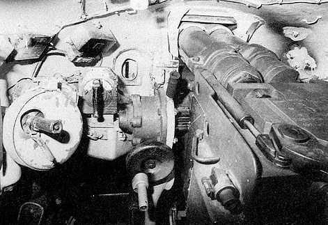
The first model of the T-54 was principally equivalent to late WWII tanks in that it featured powered turret traverse and manual gun elevation, but lacked gun stabilization or a powered gun elevation mechanism. The T-54 obr. 1946 pre-production model and T-54 obr. 1947 both used the EPB-1 electromechanical turret rotation system, also used in the IS-4 heavy tank. Beginning in 1948, it was replaced by the EPB-4 which remained standard until 1954 when it was replaced by the much more advanced stabilized STP-1 system.
On all T-54 models, the main gun has an elevation and depression limit of +18 to -5 degrees respectively. This is the hard limit, as stoppers prevent the gun from moving further. With a stabilizer installed and turned on, the limits may differ.

The EPB-1 system provided powered turret traverse at a variable speed, and unlike older powered traverse systems, it permitted relatively precise gun laying thanks to a sufficiently low minimum traverse speed. For maximum precision, the final gun lay could be carried out using the manual controls. Moreover, unlike the powered turret traverse mechanisms of earlier tanks like the T-34, the turret would not continue to rotate after the cessation of input on the control handle due to inertia, as an electric brake was installed to automatically stop the turret when the control handle is in the neutral position or if the gunner releases his grip on it. The brake will also activate to adjust the speed of the turret when the gunner changes the degree of deflection applied on the control handle.

Control of turret rotation was done with the KB-3A control unit which took the form of a spade grip with a bakelite paddle. The gunner squeezes the paddle and turns the grip clockwise or counter-clockwise to turn the turret to the right or left respectively. The control unit is essentially a rotary rheostat that registered the angle of deflection of the handle and transmitted a signal to an amplidyne amplifier. The amplidyne amplifier would then generate a high voltage proportional to the angle of deflection of the spade grip to power the turret traverse motor, which would then spin the turret at the desired speed. To switch from powered traverse to manual traverse, the powered traverse drive clutch had to be disengaged and the manual drive clutch had to be engaged.

The KB-3A control unit is located at midriff level of the gunner, close to the gun elevation drive which is just next to the cannon. The gunner's left hand would be on the traverse control grip and his right hand would adjust the elevation of the cannon. A manual turret traverse handwheel was located on the turret ring next to the power traverse control. The triggers for firing the cannon and the coaxial machine gun were both on the elevation handwheel handle. Overall, the layout of the gunner's controls was quite rational and was ergonomic enough that prolonged use was not fatiguing to the gunner, which cannot be said for the layout of the gunner's controls in some other tanks of the same era. The most major drawback to the system was the lack of powered gun elevation, forcing the gunner to elevate the gun manually via the gun elevation handwheel. Despite the ease of using the manual gun elevation drive, this still meant that gun laying was slower when compared to tanks like the M47 and Centurion Mk. 3, although did not mean that the T-54 was imprecise as manual gun elevation was still the most precise method of gun laying available in any tank at the time.
The turret could be driven by the MPB-52 electric motor at a minimum speed of 0.1 degrees per second and at a maximum speed of 13 degrees per second. For comparison, the MB-20G electric turret traverse motor of the T-34-85 allowed a maximum traverse speed of 25-30 degrees per second or a minimum speed of 12 degrees per second, with the option of a reduction to 1.5-2.0 degrees per second.
Maximum Traverse Speed: 13 deg/sec
Unlike a modern electric or hydraulic system, it took some time for the MPB-52 motor to accelerate the turret to its maximum speed.
Beginning in 1948, the T-54 used the improved EPB-4 electromechanical turret traverse system. The EPB-4 improved upon the EPB-1 in several aspects, but worked on the same operating principles and had the same control scheme. Control of the turret was done using the KB-4 control unit which had the same appearance as the KB-3A and was operated in an identical manner.
Maximum Traverse Speed: 13 deg/sec
The main improvement of the EPB-4 drive was the addition of an electronic link to a deflection sensor on the commander's cupola which allowed the commander to rotate the turret using the target designator button on his TPK-1 periscope. Additionally, the maximum turret rotation speed was increased to 11-12 degrees per second while the minimum speed remained at 0.1 degrees per second. When the commander designates a target using his TPK-1 periscope, the drive motor of the EPB-4 system is overcharged and rotates the turret at an increased speed of 13 degrees per second
The photo below, taken from the K-W Surplus store website, shows the turret traverse handwheel with its clutch control handle. To turn the turret, the clutch handle must be depressed or the handwheel will not engage with the gearing connected to the toothed turret race ring. This was designed so that when the turret was turned with the powered system, the handwheel would not spin as that could injure the gunner because it would spin quite fast due to the gearing ratio. It is worth noting that this configuration took up more space than in the T-34, because the powered traverse system of the T-34 elegantly incorporated the powered traverse control handle and the manual traverse handle into one mechanism so that the handle was automatically disconnected from the manual traverse mechanism when the gunner switched to the powered traverse mode.


Introduced on the T-54A which arrived in 1954, the STP-1 stabilizer complex for the D-10TG made the T-54 the second postwar tank to receive a gun stabilizer, albeit without full two-plane stabilization. The Centurion Mk. 3 was the first as it already featured a two-plane stabilization system in 1948. The gunner's sight is coaxially linked to the trunnion pin of the cannon to ensure its stabilization.
In April 1952, at the TsNII-173 the STP-1 "Gorizont" stabilizer was created for the D-10T gun. In May 1952, the STP-1 "Gorizont" stabilizer was installed in three experimental T-54 tanks that underwent acceptance tests in August of the same year, and in September two of them were used for field tests which they passed.
The stabilizer system is composed of multiple elements working in concert, but the focal point of our attention is the electric gun elevation control system. The minimum elevation speed is 0.07 degrees per second and the maximum elevation speed is 4.5 degrees per second.
STP-1 included the new TAEN-3 electromechanical turret rotation drive, but did not include horizontal stabilization. A new EMU-5PM amplidyne amplifier was implemented, which solved the problem of excessively high power consumption. The TAEN-3 electric drive for turret traverse is located above the manual traverse handwheel. The electric motor is mounted horizontally, as opposed to the vertical mounting of the electric motor seen in the STP-2, which we will examine later. The TAEN-3 motor was quite compact.
The gun lacked horizontal stabilization, meaning that firing on the move could only be done if the tank was travelling in a straight line. The handgrip controllers were updated to the KB-4, pictured below. KB-4 is colloquially known as "Cheburashka", in reference to the large ears of the beloved Russian cartoon mouse. Having a single controller with a pair of handgrips to control the orientation of the tank turret and gun is objectively superior to a separated layout like on the Centurion Mk.5 from an ergonomic point of view.

Modernized versions of the tank like the T-54A, T-54B, T-55, the T-62 and even the BMP-1, all used the basic design of this controller in some form or another. along with the fire control systems of many other military vehicles.
Maximum Traverse Speed: 15 deg/sec
Minimum Gun Elevation Speed: 0.07 deg/sec
Maximum Gun Elevation Speed: 4.5 deg/sec
STP-1 was decent enough, but partially by virtue of its presence alone. After all, stabilization is better than no stabilization. Various useful safety features were also implemented, including a safety device to keep the cannon under control as the tank hurdles over undulating terrain, so as to prevent the cannon from wildly swinging up and down and potentially damaging itself as well as anybody close by. A feedback system was also installed. By monitoring the load on the stabilizer motor, the stabilization system can detect if the cannon is being pushed up or down by an external force. The stabilization system will then depress or elevate the cannon in the opposite direction until the extraneous load is removed. This prevented the cannon from digging into hard objects like large rocks and concrete walls when the stabilizer was turned on.

The STP-2 "Tsyklon" stabilizer was designed by the TsNII-173 research institute from 1952-1955 and the D-10T2S variant of the D-10T gun was created with the necessary modifications for the new stabilizer. STP-2 featured a new electric turret drive and featured stabilization in the horizontal plane, which was an big improvement over the STP-1. Small batches of T-54B tanks were built in 1955 and 1956 for field trials and troubleshooting, and the tank officially entered service in 1956. Mass production of the T-54B with its new "Tsyklon" stabilizer began in 1957.
The presence of two-plane stabilization improved the chance of a hit on the first shot by 2 times compared to a single-plane stabilization system and the overall practical rate of fire reportedly rose by 1.5 times.

If you happen to be inside a T-54B or a T-55, it may be useful to know that the STP-2 can be distinguished from the STP-1 by the vertically placed electric motor on the turret ring, next to the manual turret traverse handwheel.
The turret traverse motor can be seen again in the photo below. It is the green cylinder in the same position as before.
The vertical stabilization system was carried over from the STP-1, but with some differences. Components such as the gyrostabilizer box, amplidyne amplifier and the mounting system for the electronics were modified and rearranged.
Maximum Traverse Speed: 15 deg/sec
Minimum Gun Elevation Speed: 0.07 deg/sec
Maximum Gun Elevation Speed: 4.5 deg/sec
Unfortunately, powered traverse was still quite slow even with the improved turret drive, which was not very powerful compared to the hydraulic systems being used in Patton tanks at that time. According to a T-54B manual, the turret could spin at 15 degrees per second, meaning that it would take 24 seconds to complete a full rotation. This is marginally faster than the Centurion Mk. 7, which took 25 seconds to complete a full 360 degrees, but the M47 tank (no stabilizer) was faster by 14 seconds. A U.S Armor School document on the T-54B claims that the turret could complete a full rotation in 21 seconds.
The slow turret traverse speed can be an issue for the tank if it is caught in an ambush, as the crew will not be able to react quickly enough. On the upside, the lack of flammable hydraulic fluid being circulated inside the turret was beneficial towards the survival of the crew and the tank as a whole if it was hit.
The slow traverse speed can also be a handicap when the tank is turning on the spot or zigzagging at a low speed, because the hull can turn faster than the turret. If this happens, the turret might not be able to catch up, making it jerky. This concern also exists with the vertical stabilization drive, and the ability of the gun stabilizer to maintain a fixed aiming angle is determined by its ability to cope with the oscillations of the hull when it moves over uneven ground. The faster the horizontal and vertical drives, the better the stabilization quality when quick changes of direction are involved, and consequently, the ability of the suspension to absorb vertical displacement is also a factor in stabilization quality. An increase in the speed of the tank would also necessitate faster stabilization drives.
The minimum speed of both gun elevation and turret traverse is 0.07 degrees per second. The maximum speed of gun elevation is 4.5 degrees per second. The vertical stabilizer is designed to suspend turret traverse and lift the cannon by about 3.5 degrees immediately after firing in order to improve loader access to the breech. This is part of the loader's assist function of the stabilizer, designed to ensure that the loader can load the cannon quickly and safely using ammunition from the hull. The side effect is that the gunner's primary and secondary sights will follow, thus making it impossible for the gunner to observe the effect on the target in certain situations. If the gunner wishes to maintain visual contact with the target at all times, he can request the loader to turns off the loader's assist function of the stabilizer by pressing the loader's safety button before loading a round. This returns full control to the gunner but disables the safety systems built into the D-10T2S that prevent it from firing electrically or mechanically, so the gunner must take more care to ensure that his finger is off the trigger while the gunner is loading.
A captured T-55 tested by the Israelis in 1969 yielded interesting results. The T-55 was tested on a flat sandy track at a steady speed of 15 km/h. Out of 35 shots, only 3 hit the target - a success rate of only 8.5%. This is better than the quoted value of "3% and below", but still extremely poor. Photos of the report are available on tankandafvnews. The relevant pages are Page 52 (photo), Page 53 (photo), Page 54 (photo).
The report mentions that STP-2 is only suitable for stabilizing the gunner's line of sight, not firing on the move. The poor performance of STP-2 is most likely due to the lack of range data, but the limits suspension itself definitely has an impact as well, as a hard ground was chosen to induce vibrations to the tank as detailed in Page 52. As a rule, vibrations cannot be eliminated by a gun stabilizer, but are largely handled by the suspension of the tank itself.
Six of the targets presented a broadside profile (side profile), two of the targets presented a head-on profile, and two of the targets presented an oblique broadside profile (angled profile). All of the targets were paper targets. The visible height of the target ranged from 1.45 meters to 2.45 meters, which would be representative of an average Soviet tank, but not a Western one; the Centurion is 3.01 meters tall, the M48 is 3.10 meters tall, and the M47 is an astonishing 3.35 meters tall.
At target distances averaging 1200 m with outlying targets at the unusually short distance of 600 m and the unusually long distance of 2140 m, the ratio of the number of hits to the number of rounds fired was obtained. The results are listed below:
This test was not to determine the accuracy of the gun and fire control system, unlike the test of the Centurion detailed above. This test was a simulation, with unknown and unexpected target positions, unknown distances to these targets, and so on. Another factor to consider is that these tests were held in the same extremely dusty conditions that so badly affected the crew's ability to sense the point of impact of shots. In Page 55 (Photo), it was noted that the obscuration after firing lasted for 4-5 seconds, preventing observation of the target (and the fall of the shot), making it nearly impossible to correct fire. In fact, if we scan the details of each shot as analysed and listed in the report, we can see that all of the misses (including the ones involving incorrect horizontal lay) either went high or low. Therefore, the gun was almost always laid correctly on the target, which is some credit to the horizontal stabilizer system of STP-2. The only issue was the ability of the crew to ascertain the range to the target and obtain a ballistic solution.
Out of 12 shots in phase A1, there was only one shot where the shell was off target in the horizontal plane. In phase A2, out of 11 shots, there was, again, only one shot where the shell was off target in the horizontal plane. In phase B1, out of 12 shots, we have two shots off target in the horizontal plane. In phase B2, out of 11 shots, we have one shot off target in the horizontal plane. All of the misses were due to the shot going high or low. It is very likely that in less dusty conditions, the T-55 could achieve much, much better accuracy. On a related note, the exclusive use of APDS ammunition for anti-tank purposes in the Centurion MK. 3 greatly contributed to good accuracy at all ranges, as the high velocity of APDS shells partially negated ranging errors.
From a statistics standpoint, relying on this report to generalize the performance of all T-55 tanks in all conditions will be erroneous. Therefore, I ask the reader not to take any of this data at face value. This test cannot be used to represent the majority of T-55 tanks in real battle, and certainly not T-55 tanks in Europe, where environmental conditions are very different. Take this little analysis as supplementary knowledge.
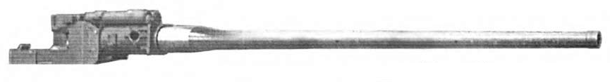
The total length of the gun is 5,608mm. The gun tube has a length of 5,350mm or 53.5 calibers, making the D10 an L/53.5 gun. It is worth noting that in the Soviet Army, the "L/" format is not used to denote lengths and there is no confusion between overall gun length and gun tube length. However, outside of the USSR, this format may be used for either overall gun lengths and gun tube lengths. For example, the German 8.8cm KwK 43 is officially listed as an L/71 gun. However, the master drawing for the KwK 43 shows that this is its full length, measured from the muzzle to the rear face of its breech, whereas the length of the gun tube alone is only 6,010mm, or 68.3 calibers.


In the T-54, the gun mount is slightly offset to the right. This offset appears to be intended to increase the working space for the commander and gunner as a significant amount of space is occupied by the equipment installed on the turret wall, whereas the loader's side of the turret is much less cluttered.


As mentioned before in this article in the section examining the TPN-1-22-11 night vision sight, nearly all T-54 obr. 1949 tanks (built and issued from 1949 to 1951) and T-54 obr. 1951 tanks (built and issued from 1952 to 1954) underwent a modernization program during the late 1950's to improve its combat capabilities to the level of the T-54B, which was the latest iteration at the time. However, the modernized tanks were not to be fitted with a fume extractor which was standard for the D10-TG and D10-T2S. Instead, a counterweight was added to the end of the barrel to simulate the load of a fume extractor to balance the cannon properly for the stabilizer to function. These unusual guns, adapted for the STP-2 "Tsyklon" but with a counterweight in lieu of a fume extractor, were designated D10-T2. The two photos below show two different T-54 models both upgraded to the standard of the T-54B. The photo on top shows a T-54 obr. 1951 and the photo on the bottom shows a T-54 obr. 1949.


The rationale behind the decision to use a counterweight instead of simply retrofitting a fume extractor to the gun barrels of modernized tanks is unclear. There is no conceivable advantage whatsoever in omitting a fume extractor other than expediency. Nevertheless, the widespread implementation of fully stabilized guns and the addition of a night fighting capability was not a trivial matter. The increase in overall combat capabilities was a large boost for the vast tank fleet of the Soviet Army.
The production of D10-T, D10-TG and D10-T2S guns at the No. 9 plant in Sverdlovsk and the No.172 plant in Perm is documented in the table below.

The basic D10-T has a weight of 1,950 kg, including the gun cradle and armoured gun mask of a T-54 obr. 1949 or any model thereafter. Together with the gun cradle and recoil system, it weighs 1,430 kg. On the M60A1, the M68 together with its gun cradle weighs 1,410 kg and the combined weight of the entire gun assembly with the gun mantlet weighs 3,260 kg. On the Leopard 1, the L7A3 with the gun cradle and gun mantlet weighs 2,900 kg. Alone, the breech and gun tube assembly of the M68 and the L7 weigh 1,122 kg and 1,282 kg respectively, but data for the D10-T is not known. From this, it can be seen that the decision to abandon a turret design with a gun mantlet as on the T-54 obr. 1947 in favour of a much more compact gun mask led to a large reduction in the mass of the cannon assembly and thus reduced the work needed to elevate or depress the cannon.
To replace the barrel, it is necessary to lift the turret off the turret ring and pull the entire cannon assembly out the back. The turret is designed to tilt forward and stay propped open to make this easier to do in the field, but it is still by no means a quick procedure.

Here's a scene of this procedure being carried out in the field. The gun is being lifted by an engineering vehicle.


The T-54 is rather short compared to the T-34, so it is quite surprising that the actual available vertical space inside the T-54 is actually quite similar to its predecessor. Measuring from floor to turret ceiling, the fighting compartment of a T-34-85 was 1.56 meters in height, or 1.585 meters, or 1.55 m, depending on the source. The T-54, on the other hand, had a maximum internal height of 1.6 meters, even though the T-54 is 2.32 meters tall while the T-34-85 is 2.7 meters tall. This wizardry was only possible because a large part of the floor of the T-34-85 is taken up by an ammunition box which stows the majority of the tank's ammunition supply. Being tall enough to stow 85mm shells three rounds deep, the box takes up a considerable portion of the tank's available vertical space. As the floor of a T-54 only needed to accommodate the torsion bars and the false floor, it could have the same internal height as the taller T-34-85. The length and width of the loader's station in the T-54 was also improved over the T-34-85 thanks to the wider turret ring, although any improvement in loading speed were probably cancelled out by the much larger bulk and weight of the 100mm rounds.


The requirement for at least 1.6 meters of vertical space was not arbitrary. According to an article published in the April 2004 issue of the "Tekhnika i Vooruzhenie" magazine titled "Основы теории и история развития компоновки танка" (Fundamentals of the Theory and History of the Development of Tank Layouts) by Vasily Chobitok, the height of the loader's station should be between 1.6-1.7 m tall and 0.5 m wide with a space of 1 cubic meter to accommodate the loader.
The commander and gunner can sit down with a reasonably comfortable allotment of headroom, but 1.6 meters is not nearly enough to let a man of average height stand upright, even with the infamous practice of choosing smaller servicemen for tank crews. According to "Foundations of Design of Armament for Self Propelled Guns and Tanks", the average height of a man is stated to be 1.7 meters, so a loader of average height would have to conduct his duties from a seated or half-standing position. As the loader's protruding cupola breaks the turret's sloping profile, he has room to stand a little straighter directly when he is directly underneath the hatch, which, conveniently, is where he needs to be in order to ram rounds into it, but otherwise, the turret is far too low to allow the loader to work with a straightened back. The low ceiling at the front part of the turret is not a problem, as there is no ammunition there that is stored above waist level at the front of the turret. The loader's seat can be unhooked from the turret and relocated to a new position near the rear of the turret, so there are two possible seated positions from which the loader can perform his duties. As usual, the seat can be folded up and out of the way for the loader to stand and move around freely in his station, but the seat can also be unhooked and stowed away for extra space. There are two fire extinguishers at the rear of the turret, directly underneath one of the possible positions for the loader's seat. The loader is also furnished with an MK-4 periscope for general visibility. The periscope is installed in front of the loader's hatch and its aperture window is surrounded by an armoured collar that is a part of its rotating mount.


The loader is drilled to return to the MK.4 periscope immediately after loading and readying the cannon to help observe the fall of every shot and help search for targets until he is called to load another round by the commander. However, in practice, if the loader is not servicing the cannon, he is either getting another cartridge ready or rearranging the ammunition into the ready racks. The periscope is marginally useful when under threat of imminent contact with the enemy as it grants the tank an extra pair of eyes, but attempting to use a non-magnified periscope to help spot targets is usually a waste of time. The greatest value of the periscope is in the psychological benefit of giving the loader a sense of his surroundings. The extra lighting may be helpful as well, since the loader's station has only one dome light.
When an IR night sight was installed beginning in 1957, the addition of an IR spotlight on the starboard side of the turret above the coaxial machine gun port had the unfortunate side effect of blocking the loader's view in the 12 o'clock sector. As such, the loader's view was restricted to the right side of the turret only, which limits his ability to assist in finding targets and completely prevents him from observing the fall of shots. However, granting forward vision to the loader is often considered superfluous given that both the gunner and commander would be looking forward and observing the target anyway. As such, the loader would be more helpful if he was focused on scanning the right side of the turret instead.
The T-54 generally had a relatively small ammunition capacity, but not all T-54 models carry the same load of ammunition. All T-54 variants created between 1947 and 1958 could only carry a measly 34 rounds - nearly half that of tanks like the M46 and the Centurion. To be fair, this was compensated by the significantly higher explosive and anti-armour performance of each 100mm shell compared to a 90mm or an 84mm one, but only to a certain extent. By having fewer rounds at their disposal, a T-54 crew must be more mindful of ammunition expenditure as the probability of obtaining a direct hit was low due to the simple fire control system and the lack of high velocity ammunition such as APDS or APFSDS.

Unlike American and British tanks and post-war German tanks, the loader in the T-54 is situated on the right side of the turret, to the right of the gun. Because of this, he loads with his left hand and not his right hand, which is the dominant side for 90% of the world's population. This has been criticized as an ergonomic failing point as it is thought that this would tire out loaders at a quicker rate, but contrary to this perception, it was never noted to be an issue during combat or during field exercises in the T-54, or in other tanks with left-handed loading including WWII-era German tanks. It is possible that the lack of any quantifiable difference is because neither of the two loading layouts are without flaws. For left-handed loading, the loader holds the base of the cartridge with his left hand and holds the nose of the cartridge with his right arm or cradles it in his right arm. Since unitary cartridges are invariably nose-heavy, this would be most comfortable for the loader. The downside is that the loader must ram the cartridge into the cannon with his left hand. For right-handed loading, the loader holds the heavier end of the cartridge with his left hand and rams it into the cannon with his right hand.

Rather than left-handed or right-handed loading, the main impediments to a T-54 loader are the length and mass of the 100mm cartridges. This was the main downside to having a more powerful gun than the American Pattons and the British Centurions during the 1950's. The base diameter of each cartridge case is 147.32mm and the length is 692mm. Naturally, the armour-piercing rounds have shorter projectiles and are therefore shorter overall compared to HE-Frag and HEAT rounds, but generally speaking, the cartridges were quite long. For comparison, the cartridges for the 105mm L7 cannon were noticeably more compact, having a base diameter of 147.3mm and a case length of 617mm. The reduced length makes them easier to handle inside the confines of a tank.

A drawing of ammunition placement in a T-54 obr. 1951 is shown below. As the arrangement of ammunition in a T-54 obr. 1949 is practically identical to that of the more historically relevant T-54 obr. 1951, we will only be discussing the latter.

The 1951 upgrade that brought the new egg-shaped turret also brought improvements in the ammunition stowage scheme. Most notably, the bevelled turret rear was filled out, and this allowed an additional five rounds to be carried. You can see these racks in the photo below.

The five rounds are stowed crosswise, tip to tail. Three rounds are stowed pointing towards the commander, and two are stowed pointing to the loader. Unfortunately, the turret bustle is too shallow for the loader to avoid the recoil stroke of the cannon when retrieving ammunition from these racks. As such, it is dangerous to extract ammunition from these racks immediately after the cannon has been loaded as the loader will not know when the gunner will decide to fire, making it impractical to lapload using these racks. These racks are deleted from the T-54K command tank variant as the space is taken up by an additional R-112 radio.

An additional two rounds are stowed on the turret wall next to the loader. The rounds are mounted facing forward. This was a rather odd design decision, since this forces the loader to hold the base of the shell with his right hand and hold the nose end with his left, even though he can only ram the round in with his left hand. This prevents the loader from extracting the round, turning around and loading the round in one fluid stroke.
Four rounds are stowed with clips at shin level on the wall of the hull, on the loader's side. These are not very convenient to use in battle if the turret is pointing forward, but they are still easier to access than the ammunition located at the very back of the fighting compartment. If the turret is pointed to the right relative to the hull, these racks will be convenient for the loader as they would then be situated directly in front of him. The presence of these four rounds decreases the available width of floor space available to the loader by 147mm (the base diameter of a 100mm cartridge case) which is somewhat inconvenient.

Twenty rounds are stowed in a metal skeleton frame rack at the front of the hull. The loader must squat down to access these racks, but the way they are placed is extremely convenient for him. These racks are placed underneath the flat part of the hull ceiling due to geometric incompatibility with the sloping front part of the hull. Underneath the 60 degree slope of the upper glacis plate, and in front of the ammo racks, is a large triangular fuel tank.


Here it is being used in an FSA-operated T-54.
Finally, there is a single cartridge stowed on the floor of the hull next to the engine compartment bulkhead. Five 250-round ammunition boxes for the coaxial machine gun are stowed on the floor of the turret, underneath the cannon, and another two boxes are placed next to the front hull ammunition racks, next to the driver's seat.
The front hull racks are the most convenient to access. They are considered the primary ready racks of the tank. Because the supply of ready rounds in a T-54 were not stowed in the turret bustle racks but were instead stowed in the front hull racks, the spring-loaded support tray featured on the 85mm ZiS-S-53 cannon of the T-34-85 was not implemented on the D10-T. Instead, the horizontally-sliding breech block was more convenient. According to Stefan Kotsch, a former T-55 tank commander in the NVA, the tank crew is trained to point the hull toward an enemy tank in a tank duel. This presents the most heavily armoured zone of the tank to the enemy and naturally makes the front hull racks a convenient source of ammunition to the loader. However, there are additional nuances with the stowage scheme, one of them being that the rounds stowed at the bottom rows of the front hull racks would be harder to access than the rounds stowed at the top rows. The loader would need to take every opportunity available to rearrange the ammunition in such a way that they are convenient to access.

The T-55 introduced new front hull racks. Instead of a simple metal skeleton frame, these racks are conformal fuel tanks with slots for ammunition. Two rounds had to be sacrificed to make the arrangement work, slashing the total number of rounds stowed in the racks from 20 to 18. The rear hull fuel tank next to the engine compartment bulkhead was removed, but the new conformal fuel tank held 300 liters of diesel which offset removal of the rear hull fuel tank and increased the total fuel capacity of the tank by 100 liters, giving the tank an extended driving range. This was a considerable performance boost, especially since no additional useful internal space was used by the new special fuel tank and a volume of 200 liters was freed up by the removal of the rear hull fuel tank. This was enough space for an additional 11 rounds, so despite losing two slots in the front hull racks, the T-55 could carry 43 rounds of ammunition, which is 9 more rounds than previous T-54 models. Contrary to the commonly held belief that the removal of the bow machine gun enabled more ammunition to be stowed, the extra ammunition was not stowed anywhere near the removed bow machine gun, and the larger ammunition capacity of the T-55 had nothing to do with it at all.
The photo below shows the front hull ammunition racks in a special T-55 training demonstrator as seen from outside its imitation turret.

The rear hull ammunition racks can be seen below (some space is being used in a non-historical manner for assorted machine gun ammunition boxes).
It is not as easy to extricate ammunition from these racks as it is from the front hull racks or from the turret racks due to the horizontal arrangement of the ammunition and the presence of the large casing deflector extending almost to the turret ring. Therefore, these racks are considered non-ready racks for reserve ammunition. As these are not ready racks, they are usually filled with HE-Frag rounds as opposed to AP or HEAT rounds which would be stowed in the front hull racks. In the event that the loader must load the cannon when the turret is turned to the right, the rear hull racks will become much easier to access and would become his primary source of ammunition besides the rounds stowed in the turret.
It is possible for the loader to load the gun from a seated position. To do this comfortably, the seat should be placed in the rear position (facing forward) as this would allow the loader to easily access the two ammunition racks in the turret without any real difficulty. If the loader carries out his duties while seated, there would be no problems with the limited vertical height of the tank and even people of above average height would be able to load the gun with ease, but the limited amount of ammunition stowed in the turret makes it impractical for the loader to remain seated for the entire length of an engagement as he would need to access the ammunition in the hull to replenish the turret ready racks. If the situation is very dire, it would be faster to simply begin taking ammunition from the front hull racks once the turret racks are depleted. The GIF below shows a loader in a T-55A loading an APDS round while seated.

Experiences in various conflicts throughout the Cold War era have indicated that it is rare for a tank to expend more than 20 rounds of ammunition in a single engagement. Most often, the tank only needs to fire around a dozen rounds before the enemy is either destroyed or routed, keeping in mind that tanks do not operate alone - the firepower of a tank platoon or tank company is very high indeed, especially if tactical numerical superiority is achieved. This knowledge is reflected in the designs of tanks like the Pershing, M46, Centurion, and all the rest. In all of these tanks, and in the tanks that came after, ammunition stowage is divided into two types; ready and non-ready. Ready rounds are stowed in racks close to the loader, so that he can load as quickly as possible during battle. During the lulls between battles, the loader refills the ready racks with ammunition from the non-ready racks. The T-54 is no worse than any of its counterparts in this sense. The total number of rounds available in the ready racks in a T-54 is 29, whereas in the T-55, it is 27 rounds. As you may recall, another four rounds are stowed by the loader's feet at shin level, but they are not necessarily ready rounds in the strictest sense.
By comparison, a 20-pdr-armed Centurion has 28 ready rounds, according to a U.S Army report posted in abridged form by Nicholas "The Chieftain" Moran on the World of Tanks forum. There are 8 rounds in the ready racks in front of the loader and 20 more rounds in the voluminous front hull racks next to the driver. A 105mm-armed Centurion, on the other hand, has only 24 ready rounds in two racks close to the loader. The front hull racks hold 20 rounds as they did before, but now the ready racks in front of the hull only contain 4 rounds. These racks can be seen in the picture below. It can be seen that the ready racks partly obstruct the loader's access to the front hull racks, making it quite difficult to extract ammunition from those racks. The T-54 is more ergonomic in this respect.

The loader in a T-54 or T-55 is able to reach virtually all of the ammunition in the tank in both ready and non-ready racks, with the insignificant exception of the single cartridge stowed on the floor next to the gunner's seat. That single round is only useful when the turret is pointed directly behind the tank, which would prevent the loader from accessing any of the other hull ammunition racks. Obviously this is a rather inappropriate position for the tank to fight in, so the lack of any ammunition in the hull in such a scenario is not a disadvantage in any way. Furthermore, the low ammunition capacity of the T-54 is not a disadvantage where modern tank combat is concerned, such as in a meeting engagement. However, it can be an issue when meeting engagements become pursuits as the Soviet Army (hypothetically) blitzes across Europe. An adequate stream of supplies must always be maintained in order to keep up the pace of combat operations, and higher dependency on ammunition resupply may prevent some tank units from exploiting gaps in the enemy's defence in certain situations, although it is rather difficult to quantify the effects of lower ammunition capacities.
A popular myth is that the Soviet Army was ambivalent towards the T-54's relatively low ammunition capacity as it was believed that the tank would be sent to its doom in massed frontal attacks against dug-in NATO tanks and anti-tank weapons, so it only needed enough ammunition for one battle as entire tank fleets could be replaced within hours of its loss. However, this was never mentioned as official policy in any documents or in any Soviet military literature and it was certainly not part of the design requirements of the T-54, or any other Soviet tank for that matter. It must be said that huge losses were expected if the Soviet Army were ever to push into Europe, but that was simply the reality of warfare on such a large scale. The only reason why the T-54 has such a small stock of ammunition compared to NATO tanks is because of the paradox of having a large gun and a small tank at the same time.
Official Soviet documentation of tank crew norms (battle drills) specifies that loading an Object 137 and Object 155 (a T-54 and T-55 respectively) from the ready racks should take no more than 13 seconds. The "minimum" grade, which is the minimal passing grade, is 13 seconds, and the "good" grade is 11 seconds, while the "excellent" grade is 10 seconds. The standards for loading speed from the other ammunition stores are more lax; when loading from any ammunition rack other than the ready racks, the "minimum" grade is 15 seconds, the "good" grade is 13 seconds, and the "excellent" grade is 12 seconds. However, these numbers are contradicted by the rate of fire figures from the manuals.
The manual for the T-55A tank states that the combat rate of fire when firing from a standstill is seven rounds per minute and that the expected rate of fire when on the move is four rounds per minute. A 1969 manual for the T-54 (T-54 obr. 1951 with no stabilizer) gives the same numbers - the combat rate of fire is seven rounds per minute when firing from a standstill and four rounds per minute when firing on the move. Considering that the very first prototype of the T-54 had a rate of fire of only 5-6 rounds per minute, and that the T-44 using the ZiS-S-53 along with the T-34-85 could attain a rate of fire of 7-8 rounds per minute, it appears that the newer turret design of the T-54 provided a more conducive working environment for the loader.
Seven rounds per minute can be considered quite average for a medium tank, albeit one with a 100mm cannon. This amounts to a nominal sustained loading speed of 8.5 seconds per shot, assuming that acquiring a target and aiming at it takes less time than that. However, keep in mind that there is a technicality in the testing procedure. The Soviet measuring criteria calls for the use of all of the ammunition in the tank, not only the rounds from the ready racks. Drawing from only the most convenient ammunition racks and containers, the loader could achieve a higher burst rate of fire.
However, it should be noted that the combat rate of fire figures given in the manual definitely does not represent the loading speed of the loader. Qualitative analyses of gunnery trials at firing ranges showed that the loading speed does not exceed 7 seconds even when firing on the move, but the actual time between shots was longer due to other factors.
Reloading while the tank is on the move is more difficult in most variants of the T-54 compared to some other tanks due to the lack of a rotating turret floor, even if that was counter balanced by the rather sluggish spinning speed of the turret. Nevertheless, four aimed shots per minute is not a bad result when compared to other tanks, as you can see in the table below.

Older models of the T-54 that lack a stabilizer may have a lower rate of aimed fire when firing on the move as the time taken to acquire the target is much longer due to the need to halt or slow to a crawl in between shots as opposed to the T-54B and T-55 where the gunner can scan for targets while on the move.
According to the September issue of the 2008 edition of the "Техника и вооружение" magazine, the ammunition loadout of a typical Soviet T-54 and T-54A consists of 12 HE-Frag rounds, 4 "Shrapnel" rounds, 6 HEAT rounds and 12 AP rounds. The loadout of a Soviet T-55 and T-55A consists of 18 HE-Frag rounds, 4 "Shrapnel" rounds, 6 HEAT rounds and 15 AP rounds. The "Shrapnel" rounds most likely refer to 3USh-1 rounds with the 3Sh5 Flechette shell which contains 1,800 steel flechettes packed in a special casing which is fuzed to break apart during flight to release the flechettes. Due to the rarity of this round, most tanks probably substituted them with standard HE-Frag rounds.
The standard loadout of a Yugoslavian T-54 consists of 17 HE, 11 AP and 6 HEAT.
Two types of ammunition casings are available; D-412 steel cases, and Kh-415 brass cases. D-412 weighs 8.50 kg, whereas Kh-415 weighs 6.0 kg. Brass cases are mostly used for AP, APDS, APFSDS and HEAT ammunition to improve firing consistency, while steel cases are mostly used for HE-Frag ammunition as accuracy is slightly less important.
A tank's target is not necessarily another tank. Most of the time, it isn't. And to that end, the average T-54 tends to have a larger number of HE-Frag ammunition in its loadout compared to its stock of anti-armour ammunition. Out of a total load of 34 rounds, a T-54 with a standard loadout can carry 10 HE rounds and 4 Frag rounds. When the ammunition capacity was increased to 43 rounds in the T-55 upgrade, the number of HE rounds increased to 18 rounds, but the number of Frag rounds remained the same. However, the implementation of HE-Frag rounds made Frag ammunition redundant. The number of HE-Frag rounds carried is the sum of HE and Frag rounds.

The UOF-412 cartridge weighs a total of 30.2 kg. The OF-412 shell itself weighs 15.6 kg while the propellant charge contained within the steel or brass casing weighs 5.5kg. The explosive charge is TNT. Though it was far from unusual to have a TNT filler, more brisant and powerful fillers such as various mixtures of Amatol and A-IX-1 existed, and it is not explained in any literature why TNT continued to be used. Perhaps the most plausible explanation is that TNT was simply easier to cast and much cheaper and the expenditure of HE-Frag shells in times of war was expected to be so high that the cost efficiency of using TNT outweighed all of the drawbacks.
A 20 pdr. HE shell, for instance, weighs 7.838 kg and contains an explosive charge of 0.6 to 0.75 kg of TNT or Composition B (60% RDX, 40% TNT), depending on the exact model of shell. The OF-412, on the other hand, weighs twice as much at 15.6 kg and contains twice as much explosives with a 1.46 kg TNT explosive charge. For every 100mm HE round that the T-54 carried, a Centurion Mk. 3 would need two 20 pdr. ones to match it in payload. The raw kinetic energy of OF-412 shells is also much higher, not only because it is of a larger caliber and weighs twice as much but also has a higher muzzle velocity of 892 m/s compared to just 602 m/s for a 20 pdr. HE shell. This makes OF-412 very useful against hardened structures as it is capable of penetrating reinforced concrete pillboxes and heavy field fortifications when the PD fuze is set to the "HE" mode for delayed detonation. The range of the shell is also extended, making the T-54 more useful for indirect fire.
Muzzle Velocity: 892 m/s
Cartridge Mass: 30.2 kg
Projectile Mass: 15.6 kg
Explosive Charge Mass: 1.46 kg
OF-412 is is topped off with an RGM-6 point detonating (PD) fuse. The fuze is armed only by centrifugal forces, thus making it inert until it has been fired through a rifled gun barrel. There are two fuze settings with three possible firing methods. The superquick setting is marked with an "O" and the delayed setting is marked with a "З" (a Cyrillic "Z").

The superquick setting detonates the shell 0.027 seconds after impact and the delayed setting detonates the shell 0.063 seconds after impact. Superquick action guarantees reliable detonation in snowy or swampy ground, and delayed action gives a small time allowance for the shell to penetrate its target before detonating. Keeping the (waterproof) safety cap on the fuze has a delaying effect on the fuze (refer to the table above) and switches the round from the "Frag" mode to the "HE" mode. Setting the fuze is the loader's job, but it is the commander who dictates which setting is used. The variety of fuzing possibilities gives OF-412 an added degree of flexibility against targets of all types, meaning that the T-54 has to use fewer rounds overall compared to an early Centurion equipped with the 20 pdr. gun. This offsets the difference in ammunition quantity.
The delayed fuzing feature is beneficial to overall efficiency when the T-54 is used in an indirect fire role. When RGM-6 fuze is set to the delayed mode, OF-412 can be very useful against underground or dug-in positions, as the shell assumes an arcing ballistic trajectory when shooting at long range.
The fuze slot at the tip of the shell is also compatible with the V-429 variable delay fuse designed in the 60's. The V-429 fuse is point-detonating and armed by centrifugal forces, like RGM-6. The V-429 fuse differs from the V-429E (used in the 115mm U-5TS and 125mm D-81T), which is armed by the braking effect from the unfolding of the stabilizer fins of the shell. Like the RGM-6, the V-429 has two possible settings: superquick and delayed. The main advantages of the V-429 are that it is waterproof even without a waterproofed safety cap, and it has additional safety features to prevent the detonation of the shell even if the fuze is accidentally set off.

3UOF10 is a more modern cartridge, incorporating the 3OF32 shell. This round was introduced in 1975. 3OF32 is designed to produce a more optimal pattern of fragmentation for increased casualties but also remain sturdy enough that it can penetrate reinforced concrete targets without breaking up. The 3OF32 shell is furnished with the V-429 fuze as standard.
Muzzle velocity: 900 m/s
Complete round mass: 30.36 kg
Propellant Charge Mass: 5.6 kg
Mass of Shell: 15.96 kg
Explosive Charge Mass: 1.7 kg
Explosive Type: A-IX-1
Number of Preformed Fragments and Their Mass:
With a mass of not less than 0.5 g: 1993
With a mass of 0.5 g to 2 g: 814
With a mass of 2 g to 15 g: 928
With a mass exceeding 15 g: 251
Statistical Average Mass of Fragments: 6.2 g (median is more important, but the statistic is not provided)
Velocity of Fragments and Ratio of Fragment Velocities:
100% - at least 1040 m/s
90% - 1060 m/s or more
80% - 1080 m/s or more
Interestingly, the 3OF32 was later used in the 2A70 low pressure cannon of the BMP-3. In that particular application, the low velocity of the shell further decreases the penetration of the shell into soil and snow, thus improving its fragmentation value, but the low velocity also reduced the energy of the shell and reduced the time allocation for it to penetrate hard obstacles, making it exceedingly unsuitable for bunker busting. It could, however, still be used to remove earth and log fortifications.
Throughout the 1950's, conventional full-caliber steel armour-piercing rounds were the only armour-piercing round available for the T-54, but even after reliable fin-stabilized HEAT shells became available in 1961, conventional full-caliber shells remained the standard ammunition type for dealing with tanks with the less numerous HEAT shell being reserved for more heavily armoured tanks. As a rule, this included heavy tanks like the M103 and the Conqueror or main battle tanks like the M60A1.
The typical example of this type of ammunition was cheap, reliably lethal, and tended to be more accurate than other types of ammunition. Out of a standard combat load of 34 rounds, a T-54 carried 12 armour piercing rounds and the remainder was taken up by HE-Frag rounds. The T-55 had an expanded ammunition capacity of 43 rounds and carried 15 armour piercing rounds in a standard combat load. When APDS officially became available in 1967, it replaced full caliber steel armour piercing ammunition entirely.
Throughout the military career of the T-54 series in the USSR and in most of its satellite states, AP shells were preferred over HEAT shells despite the obvious superiority of the latter in armour penetration power. When HEAT became available for the T-54, the ratio between AP and HEAT ammunition was 2:1, and when the T-55 tank was introduced with a larger ammunition capacity, it carried AP and HEAT ammunition in a 2.5:1 ratio. For example, according to ex-NVA tank commander Stefan Kotsch, a standard combat loadout for an NVA T-55 was comprised of 15 APDS rounds, 6 HEAT rounds and 22 HE-Frag rounds. It was the same in the Soviet Army.
The point blank range for BR-412B and BR-412D is 1,220 m for a target with a height of 2.7 meters, representing a NATO tank. This means that the gunner can set the sight at 1,220 m prior to an engagement, and when an enemy tank is spotted, the gunner simply aims for the center mass of the target. If the target is exactly 1,220 meters away, the shot will land on the turret ring. If the target is closer than 1,220 meters, the shot may land on the turret. If the target is slightly further than 1,220 meters, the shot may land on the hull. Either way, a hit is quite likely within the margin of error provided by the point blank distance. This is a faster method of engaging tank-type targets, and given the high threat posed by tanks, it is probably the preferred gunnery technique employed by most T-54 gunners. For precision gunnery, the range reading obtained by stadiametric rangefinding can be used to further enhance to probability of a hit.
When the T-54 entered service in the Soviet Army, there were only two types of armour piercing ammunition available for it. BR-412 AP, and BR-412B APBC. BR-412B was formally introduced sometime around 1946 (apparently, it was already in production by early 1945, but not issued) as a modified version of BR-412, featuring a blunt nose and a ballistic cap to maintain an aerodynamically pointed nose. The shape of the blunt nose is similar to the older 57mm BR-271 APHE-T shot in that it has a small bump on the tip, but the bump is completely flattened and not rounded. As the ballistic properties of the two rounds were different, chiefly due to this ballistic cap, it made little sense to keep the worst of the pair, so the early incarnations of the T-54 were stocked entirely with BR-412B.
When fired from the D-10T, the probable deviation of BR-412B at a distance of 1 km is 0.3 meters in the horizontal axis and 0.3 meters in the vertical axis. At a distance of 2 km, the probable deviation is 0.5 meters in the horizontal axis and 0.6 meters in the vertical axis.

The quality of the steel is considered high, and the hardness is respectably high as well. The hardening of the shell progresses uniformly - hardest at the tip and areas close to the surfaces, and slightly softer at the center. In contrast, wartime production 76mm BR-354B for the ZiS-3 gun ranges from 47 points Rockwell C to 38 points (451 BHN to 351 BHN) at the tip alone. Such shells were prone to shattering on impact with hard armour. A hardness of at least 600 BHN at the tip - which BR-412B achieves in excess - is necessary to prevent this from happening. The BR-412B shell is fired from the D-10 series of guns at a chamber pressure of 294.2 MPa.
Below are two different analyses on different BR-412B samples. Both were done by the Ministry of Munitions in the U.K, but at different times. The one on the right was done in 1963 with ammunition from an unspecified recent conflict, and the one of the left was done in 1958 with ammunition taken from a captured Egyptian SU-100 from the Suez Crisis.


According to a U.S army document analyzing the Soviet 76mm BR-354B, it was mentioned that American armour piercing shots are generally hardened to approximately Rockwell C 60 (654 BHN) at the nose. By this metric, BR-412B can be considered on par with U.S ammunition.
With successful armour perforation, the lethality of BR-412B will be high due to the larger mass of the projectile compared to 85mm and 90mm guns firing the same type of shell, and it is further augmented by the 65-gram explosive charge of A-IX-2 at the base of the shell which ensures the complete destruction of the projectile after armour perforation. A British evaluation states that the detonation of the explosive charge has the effect of shattering the rearmost portion of the shell into five to six pieces as the shell exits the rear of an armour plate, supplementing the large spray of secondary projectile fragments and spall from the armour plate itself. As such, the cone of fragmentation is increased in size and a larger number of internal components will be hit. These five to six large chunks of hard steel may also produce even more fragmentation as they impact the interior walls of the target. In addition to that, the high energy of these chunks has a much greater chance of detonating ammunition inside the tank compared to smaller fragments. Contrary to how AP shells with a base charge are often perceived, the explosion will not send fragments in all 360 degrees like a grenade. It must be remembered that the walls surrounding the cavity containing the explosive charge are very thick - too thick to act as an effective fragmentation casing.
Nevertheless, the killing power of the shell is augmented to some extent by the percussive effect of the blast, which has greater power than that of an F-1 fragmentation grenade (which holds 60 grams of TNT), even though most of it is spent in cracking the base of the shell into several pieces. Confined inside the small spaces of a tank, the effect of the blast is magnified and the incendiary effect of A-IX-2 increases the chance of igniting fuel and ammunition, not to mention burning the crew and internal equipment. While 65 grams may not seem like much, A-IX-2 is a particularly useful explosive-incendiary compound because it contains aluminium as a fuel additive. A-IX-2 consists of 73% RDX, 23% aluminium powder, and 4% phlegmatizing wax. The aluminium powder content produces an incendiary effect, because aluminium powder is used as a fuel additive to increase the heat of combustion (Türker 2016, p. 426).
The high aluminium content in A-IX-2 means that there will be some unburnt aluminium powder dispersed into the surrounding air, where it will burn at reduced rate due to the reduced oxygen level in the air (and also in the RDX itself, as RDX is oxygen deficient) and due to the increased concentration of gaseous byproducts from the explosion. Augmenting this effect is the fact that the burning of aluminium generates an alumina (aluminium oxide) coating over the surface of the aluminium particles. The alumina acts as an insulation layer, thus delaying the burning of the aluminium itself so that the efficiency of combustion is reduced. This has the effect of extending the duration of combustion and thus increasing the explosive impulse, extending the release of heat energy, increasing the explosive impulse, extending the radius of the incendiary effect, and increasing the probability of igniting other flammables in the vicinity of the explosion. Because of these factors, all HE-I shells for aviation cannons and APHE shells developed in the USSR after 1940 used A-IX-2 exclusively. On the other hand, medium to large caliber HE-Frag shells usually had an A-IX-1 or Trotyl filler, presumably for cost reasons.
Muzzle velocity: 895 m/s
Mass of Complete Round: 30.1 kg
Projectile Mass: 15.88 kg
Mass of Explosive Charge: 0.065 kg
Explosive Charge Type: A-IX-2
Chamber Pressure: 294.2 MPa
According to Yugoslavian tests, BR-412B could only defeat the front turret armour of a T-54A at a distance of 500 meters. This means (indirectly) that BR-412B can perforate 200mm of cast steel armour of medium hardness set at an angle of 0-30 degrees at 500 meters. This is well within the figures listed below.
Penetration at 0 Yards:
164mm at 30°
133mm at 45°
96mm at 60°
59mm at 70°
Penetration at 1,000 Yards:
140mm at 30°
115mm at 45°
82-85mm at 60°
51mm at 70°
Source: British test report: DEFE 15/1107 "The Performance of Russian SU 100 APHE/T Shot UBR-412B Against Armour Plate"
All values are for a 50% chance of penetration.
The British use the V50 standard instead of the Soviet/Russian V80 standard. If the document were Russian, the distance where the shell would be able to penetrate the armour of the tank would be listed as shorter. Besides that, the criteria for what constitutes armour penetration differs substantially from the Russian criteria. The British and American criteria dictates that at least 50% of the projectile mass must end up on the other side of the armour plate per a certain velocity, or in more practical terms, a certain distance (as the function of distance is the derivative of velocity). This forms the basis of the V50 standard. The Russian criteria as manifested in most firing tables dictates that at least 75% of projectile mass must be found on the other side of the armour plate. In actual certification testing, though, an 80% standard is used. This is responsible for the differences in penetration values of Russian ammunition in both military and civilian literature.
These figures are backed up by this page of the report:

Each vertical divider on the chart represents 250 meters.
All values are in V50 standard. The hardness of the target plates is listed below.

As usual, the ballistic arc of the shell is not significant enough to affect armour penetration on sloped targets by any significant amount. According to Soviet firing tables reproduced in the CIA report "Technical Information on the 100-mm Gun and Other Armament on the T-54 Tank" from 1960, the angle of descent of BR-412B and BR-412D is 0.4 degrees at a distance of 1 km and 1 degree at 2 km.
In terms of penetration power and post-penetration lethality, BR-412B is nominally superior to 90mm M318A1 APCBC. However, the T-54 did not have access to "premium" ammunition like M304 HVAP, though 100mm BR-412P HVAP ammunition was built in some small quantities and was considered for full issuance. Ultimately, regular steel rounds were considered adequate and BR-412P never saw the light of day. For situations where steel AP was inadequate, multipurpose HEAT ammunition could do the job better than tungsten cored HVAP ammunition while simultaneously offering a secondary anti-personnel function thanks to its explosive charge and thick steel casing.
Once full armour perforation is achieved, the results are utterly devastating. (The photo on the left is actually from a BR-412D penetration, but the effect is much the same).


As a rule of thumb, the entry channel in a thick armour plate is always larger than the actual caliber of the shell and the exit channel is typically equally large if not more so. A blast of armour fragments is ejected at extremely high speed into the tank, followed by shards of the shell, followed by the shell itself which may or may not be intact. If intact, the explosive filling at the base of the shell detonates and fragments the steel body, creating additional fragmentation and increasing the spray cone angle of fragmentation after clearing the armour plate. The MD-8 fuse embedded in the rear of the shell has a delay to ensure that the explosive charge detonates a certain distance inside the tank past the armour, making it more deadly than if it detonated immediately after perforating the armour plate, or during the penetration phase inside the armour plate.
Although it was originally intended for defeating increasingly thick German tank armour near the end of the Second World War, the intended targets for the BR-412B shell quickly changed to American tanks. The M26 Pershing, and by extension the M46, both have a 100mm-thick cast steel upper glacis angled at 46 degrees. Factoring in the lower efficiency of cast armour compared to rolled armour and the information from the British tests, it should be vulnerable to BR-412B at a distance in excess of 1.5 km. As for the M47, Yugoslavian ballistic testing found that the 100mm cast steel upper glacis with a slope of 60 degrees can be perforated by BR-412B at a distance of 750 meters. This would not have been an acceptable result by WWII standards as average tank combat distance was between 200-800 meters, but as tank optics improved, this became rather close for comfort. Nevertheless, the T-54 still nominally outranges the M47.
According to page 25 of WWII Ballistics: Armour and Gunnery, a 100mm cast armour plate within the 220-300 BHN hardness range is 93% as effective as rolled armour with a hardness of 240 BHN at a 0 degree impact angle against 100mm armour piercing projectiles. The book does not list the relative efficiency of cast armour when it is sloped, but this information agrees with the results of the Yugoslavian tests, implying that the efficiency does not change significantly with the angle of the plate.
The M47 became the mainstay of many European armies including the West German Bundeswehr, but the improved M48 was the backbone of the U.S Army for most of the Cold War. The upper glacis of the M48 is cast steel, 110mm thick sloped at 60 degrees, which is more somewhat formidable than the upper glacis of the M47. 110mm of cast steel should be equivalent to around 102mm of rolled steel, making the upper glacis of the M48 approximately on par with the T-54 itself. A detailed report on the performance of BR-412B against the M48 is detailed in this Tank Archives post, courtesy of Peter Samsonov. The original 1958 report is titled "Броневая Защита Американского Среднего Танка М-48". Soviet testing revealed that BR-412B was not capable of penetrating the upper glacis of the M48 even at point blank range, which should not be surprising as the Yugo test report mentions that BR-412B was not capable of perforating the upper glacis of a T-54A. However, the lower glacis of the M48 could be perforated at 2,500 meters. It is interesting to note that the Soviet report concluded that BR-412B needed an impact velocity of 940 m/s to defeat the upper glacis armour of the M48, which is substantially higher than the muzzle velocity achieved by firing BR-412B out of a D-10 or a BS-3 gun. Defeating the upper and lower side hull armour of the M48 from a side angle of 30 degrees (from the longitudinal axis of the tank) is possible from a distance of 500 meters.
The turret of the M48 is weaker than the upper glacis - mostly because it is not nearly as sloped as the upper glacis - but it is still very well rounded and quite formidable. The thickness of the front turret face at the gun mantlet region varies from 178mm to 100mm, with sloping that ranges from 14 degrees at the very bottom edge of the turret where it is thickest to 56 degrees near the turret roof, where it is much thinner, but no matter what the thickness or slope is, the thickness on the front turret face invariably measures up to exactly 7 inches, or 178mm. The thickness reduces considerably beyond the immediate front turret face, but this is somewhat compensated by additional horizontal slope, although the final LOS thickness is still less than the front turret face. By referring to the penetration values given earlier, we can see that the front turret face cannot be considered well protected against BR-412B.

The gun shield overlaps the front turret face slightly, but the area of overlap is very small and the gun shield itself is negligibly thin. The most significant portion of the gun shield is 110mm thick, sloped at 30 degrees, which comes out to 127mm in LOS thickness. This should be vulnerable to BR-412B at a distance of more than 1,200 meters.
Overall, BR-412B should be able to perforate the area near the base of the turret at distances in excess of 1,250 meters, and the area near the roof should be highly vulnerable at a distance of at least 800 meters. This was inexcusable, since BR-412B was by no means new by the time the M48 entered service. For this reason, the Soviet report "Броневая Защита Американского Среднего Танка М-48" concluded that 100mm rounds are generally effective against the M48, despite the inability to defeat the upper glacis armour. However, better ammunition in the form of BR-412D became available at the same time that the M48 entered service in the U.S Army.

Steel shell with a soft steel armour piercing cap. This shell formally replaced the BR-412B as the standard anti-armour round in 1953, but it came as early as 1951 as an component of the loadout of the T-54 obr. 1951 (the brand new TSh2-22 sight for the T-54 obr. 1951 had a range scale for BR-412D). Both BR-412B and BR-412D continued to be used side by side for some time, so in actuality, BR-412D supplanted the BR-412B rather than replaced it outright in Soviet service. Some former Soviet satellite states were still using BR-412B into the 2,000's until they eventually scrapped their T-54 tanks completely.

The armour piercing cap prevents the shell from breaking up when it impacts thick steel plate at high velocities. Controlled fracturing of the nose of the shell is beneficial towards penetration on sloped targets, but shattering of the shell will neutralize it completely. This shell is superior to the BR-412B on both low and high obliquity targets, but the difference is most noticeable at low obliquity. In page 10 of "Mechanisms of Armour Penetration" by Niko Holkko, it is shown that uncapped APBC and AP shells are more effective on thin plates (0.4 calibers) at all angles compared to APC and APCBC shells, but the inverse is true when the plate thickness reaches 0.45 calibers and above. On a thick plate (1.3 calibers), APC and APCBC rounds vastly outperform APBC at 60 degrees obliquity. In practical terms, the superior penetration on thick sloped armour makes BR-412D a favourable choice when engaging modern tanks of the era such as the M47 and M48.
Muzzle Velocity: 887 m/s
Complete Mass of Round: 30.4 kg
Projectile Mass: 15.88 kg
Mass of Explosive Charge: 0.061 kg
Explosive Charge Type: A-IX-2
Chamber Pressure: 294.2 MPa
Point-blank ranges:
For a target height of 2.0 m - 1,070 m
For a target height of 2.7 m - 1,220 m
For a target height of 3.0 m - 1,270 m
For armour penetration, Zaloga gives these figures (Link):
Penetration at 0°:
100 m: 200mm
500 m: 185mm
1000 m: 170mm
1500 m: 155mm
2000 m: 125mm
Penetration at 30°:
100 m: 150mm
500 m: 140mm
1000 m: 130mm
1500 m: 120mm
2000 m: 100mm
These values are in Soviet standard. Soviet target plates had a hardness of between 250 to 350 BHN.
Penetration at 0°:
100 m: 250mm
1.0 km: 185mm
1.5 km: 170mm
(Source unknown)
The CIA report "Technical Information on the 100-mm Gun and Other Armament on the T-54 Tank" has this penetration table for the BR-412D:

Comparing these figures to Zaloga's, we can see a significant discrepancy. The CIA's figures are much higher, especially when we go up to and beyond 2,000 meters. At 500 m and 1,000 m, the CIA's figures are 10mm higher for a 30-degree impact and 15mm higher for a 0 degree impact. At 2,000 meters, the CIA's figures are 20mm (!) higher for a 30-degree impact and a 30mm (!) higher for a 0-degree impact. The figures in the report are apparently taken from Soviet documents.
According to these figures, BR-412D should be more than capable of perforating the front hull armour of a Leopard 1 at distances in excess of 1,500 meters. The Panther's 82mm upper glacis sloped at 55 degrees was found to be penetrable at a distance of 1,500 meters. As for the M48, the BR-412D should have an effective range of several hundred meters more than the BR-412B when attacking the turret, but the most noticeable advantage is that BR-412D should be able to perforate the upper glacis of the M48 at a distance of around 500 meters, based on the difference in slope modifiers.


3BM8 is an APDS shell for the D-10T that officially entered service in 1967. However, mass production began some years prior to 1967, and the modified TSh2B-32P sight with markings for APDS rounds was introduced in 1965.


The sight is ordinarily zeroed to a distance of 1,200 meters or more. The drawing below depicts a method of zeroing the sight in field conditions by using a landmark.
By displaying all of the range scales in the viewfinder and not on an external dial, the gunner can conduct the entire target acquisition procedure without removing himself from the sight and losing visual contact with the target. This problem was solved in the Centurion in a rather creative way; a mirror was placed in front of the gunner's left eye at such an angle that the gunner could see the range drum with his left eye as he adjusted it, and then - by just moving his eyes - return to the sight and resume targeting.
To use the rangefinder, the gunner only needs to bracket the target tank between the stadia lines and read the figure corresponding to the height of the target, and then turn the range adjustment dial until the horizontal line is on the correct range scale mark for the desired ammunition type. It is also possible for the gunner to use the multitude of chevrons and lines that form the reticle of the sight viewfinder and combine them with his own memorized information of tank widths and lengths to obtain a range estimate.
The sight aperture port cut into the turret was protected by a pane of glass. This was merely a thin barrier to prevent external debris and water from entering the turret through the aperture. It had no ballistic protection whatsoever.


While Soviet-built tanks had a stadium-shaped glass cover that was affixed to a raised lip that is shaped accordingly, Polish-built T-54 tanks used an oval-shaped glass cover. This can be used to identify the origin of the tank regardless of its markings.

TSh2B-32
TSh2B-32 was first implemented in the T-54B. The sight was practically identical to the previous articulated telescopic sights with the main difference being that it was designed to connect to the new STP-2 gun stabilizer. This sight continued to be used in the T-55 series as the fire control system did not change. The configuration of the viewfinder markings follows the latest variant of the TSh2B-22. As shown in the photo below, there were range scales for HE-Frag with a full charge, APCBC, HEAT and the coaxial machine gun. Additionally, the markings for HE ammunition with a reduced charge were permanently removed as this type of ammunition had become obsolete.

TSh2B-32P
In January 1965, the TSh2B-32P was installed in the T-54B and T-55. The only difference between it and the TSh2B-32 is the new range scale for 3UBM6 APDS ammunition. The "P" in "TSh2B-32P" stands for "subcaliber". Tanks that had the TSh2B-32 equipped were modified by swapping out the viewfinder glass disc with a new disc with the additional markings to transform them into the TSh2B-32P.


Besides the range scale for subcaliber rounds, there are no other notable differences. It is worth noting that the scale for subcaliber rounds can be used for both APDS (3BM8) rounds and APFSDS (3BM19, 3BM20, 3BM25) rounds due to the very similar ballistic trajectories of both types of ammunition and the low precision of this type of range scale. For instance, the 3BM20 APFSDS shell had a point blank range of 1,690 meters against a target with a height of two meters and a point blank range of 2,040 meters against a target with a height of three meters while the 3BM8 APDS shell had a point blank range of 1,680 meters against a target with a height of two meters and a point blank range of 2,020 meters against a target with a height of three meters. In realistic conditions, this small difference is practically imperceptible.

TPN-1-22-11

In the year 1957, the T-54 entered its tenth year of formal service in the Soviet Army and also the tenth year of its continuous evolution, becoming the T-54B. The T-54B became capable of night fighting with the installation of the TPN-1-22-11 active infrared imaging sight and the accompanying L-2 "Luna" infrared spotlight. Although the performance of the night vision system is far from impressive by modern standards, it was a modern product for its time and the inclusion of a night vision sighting system in the T-54B together with a night vision TKN-1 optic for the commander gave it a distinct edge over the contemporary M48A2 which lacked any form of night vision sighting equipment whatsoever. Only the M60A1 from 1962 was equipped with a night vision sight (M32) and a night vision optic for the commander (M36). The armoured hood for the TPN-1 night sight on the T-54B can be seen in the photo below in front of the commander's cupola.

TPN-1-22-11 can operate in either the active infrared imaging mode or the passive light intensification mode. In the active infrared imaging mode, the infrared light supplied by the L-2 "Luna" spotlight mounted coaxially to the main gun is visible through the sight, allowing the gunner to identify a tank-type target at a maximum distance of 750-800 meters. This was quite good for night vision equipment from the 50's. The L-2 "Luna" spotlight uses an incandescent bulb and consumes only 200 W, which is quite weak for a spotlight. In the passive mode, the sight employs a 1st Generation light intensifier tube to amplify ambient light, providing a nominal maximum identification distance of 400 meters for a tank-type target under lighting conditions of no less than 0.005 lux. The sight has an adjustable sensitivity to allow the gunner to obtain the best image under different lighting conditions.

TPN-1-22-11 has fixed 5.5x magnification, and a narrow field of view of 6 degrees. The magnification is quite reasonable for a night vision device, as the IR sight for the Chieftain only had a 3x magnification. The viewfinder is extremely simple, as you can see below. The tip of the chevron is sighted for BR-412D AP rounds for a distance of 200 m, going down to 400 m at the upper tip of the vertical reticle line below the chevron. A more comprehensive adjustment system was not included as the short range of the TPN-1-22-11 night vision system limited engagement distances to 800 meters or less anyway.
The TPN-1-22-11 has an internal lightbulb to facilitate aiming at night. It is either on or off without the option of dimming, but it can be turned on in either the day mode or the night mode as the gunner wishes. It is preferable to remain in the day mode with an illuminated reticle when operating during sunset or twilight hours.
TPN-1-22-11 is similar to the telescopic primary sight in that it is not independently stabilized. It is only connected to the main gun by a mechanical linkage as shown in the drawing below. Disregarding its night vision capabilities, the sight is mechanically and optically quite simple.
During the late 50's, nearly all T-54 obr. 1949 tanks (built and issued from 1949 to 1951) and T-54 obr. 1951 tanks (built and issued from 1952 to 1954) underwent a modernization program to improve its combat capabilities to the level of the T-54B, which was the latest iteration at the time. The technical details for the modernization of older tanks - excluding the troublesome obr. 1947 model - to the standard of the T-54B model was prepared simultaneously with the development of the T-54B itself, thus ensuring that a large part of the Soviet Army's T-54 fleet would be kept up to date at the highest available level of technology. One of the upgrades was the addition of night fighting capabilities via the installation of the TPN-1-22-11 night vision sight and the associated equipment, including the L-2 "Luna" spotlight and a new power supply system to handle the new equipment. The T-54-2 in the two photos below is an example of a tank modernized to T-54B standards. Note the counterweight at the muzzle of the cannon. This will be examined further in the article.


The addition of a night fighting capability to the vast majority of the T-54 tanks in the Soviet Army represented a significant tactical advantage, considering that the M60A1 was only being produced in relatively small numbers during the early 60's and the M48A2 modernization in 1956 did not grant the U.S Army's large fleet of M48 Patton tanks a night fighting capability. Even when the M48 gained a xenon spotlight and the M32 periscope in 1963 as part of the M48A3 upgrade, the T-54 retained an advantage because its night sight had a passive image intensifier mode that made it possible for the gunner to engage targets without turning on its infrared spotlight, whereas the enemy M48A3 and M60A1 tanks were forced to rely entirely on active IR or white light illumination.
The night vision equipment was tested in a British/Israeli assessment of the T-55, among other things. The full report is available in the Tanks and AFV News site. The relevant page of the report can be viewed here (link). According to the test, TPN-1-22-11 allowed the gunner to see:
| Target | Distance (m) |
| Man | 200 |
| Topless Jeep | 400 |
| Chieftain (from behind) | 400 |
Another explanation is that the TPN-1-22-11 has lackluster performance simply because it is older than whatever the Chieftain uses by almost a decade, but then, why did the report mention that the equipment was "suspect in nature"?
Volna Fire Control System
The T-55AM deep modernization programme of 1983 involved a total overhaul of the fire control system as well as a base overhaul of the engine and other essential components.

TShSM-32PV

Introduced as a complement to the Volna fire control system, TShSM-32PV is substantially more advanced than the previous telescopic sights used in the T-54 series. TShSM-32PV features a viewfinder that is very similar to the TPD-K1 in layout, especially with the removal of the range scales and its substitution with a more space efficient dial-type range indicator at the top.
The magnification of TShSM-32PV is practically identical to its predecessors; either 3.5x power magnification or 6.9x. The sight offers a field of view of 18 degrees in the low magnification setting and 9 degrees in the high magnification setting. The sight is independently stabilized in the vertical plane with a maximum accuracy of 0.3 mils, which is quite good. At 1000 m, the sight will have a maximum deviation of 0.3 meters from the point of aim.
Now that the sight is linked to an analogue ballistic computer, additional features had to be implemented in order to add more functionality. An LED tab at the bottom of the viewfinder displays the ammunition type and the range. The range dial at the top of the viewfinder spins (different dial rings spin at different rates via a differential mechanism) to display the range equivalent for different types of ammunition. In the right hand side drawing of the viewfinder above, you can see that the number "140" displayed in the range display tab, and the range dial for BK (HEAT ammunition) set to "14". This means that the target is 1400 meters away, and HEAT is selected. Switching the ammunition type will reset the range dial accordingly.
The same reticle design was retained in the TShSM-32PV, as was the method of gun laying. Once the range was automatically inputted into the sight via the BV-55 ballistic computer, the reticle drops a certain amount. The gunner must then manually raise the reticle and lay it on target. This is not as convenient as having the cannon raise automatically while the reticle remains static, as was the usual in digitized Western FCS appearing in the late 70's and early 80's.
1K13-2

The sight has a field of view of 5 degrees in the daylight setting or 6°4' in the nighttime setting. It is independently stabilized in the vertical plane, with +20° elevation -7° depression.
 |
| Daytime mode |
The sight's active infrared imaging system is slightly improved over the TPN-1-22-11. Now, the viewing range in the active mode is increased to 1200 m, though the light intensification unit has not been improved, meaning that the 1K13-2 sight still has a viewing distance of only 800 m under ambient lighting conditions of no less than 0.005 lux. The identification distance and image clarity improves with increasingly brighter lighting conditions, but excessive brightness can oversaturate the image, and overwhelming brightness can overload and possibly damage the sight.
In accordance with the extended viewing distance in the active infrared mode, the sight is now equipped to adjust the superelevation of the reticle, just like the telescopic sights described before. This is to enhance firing accuracy at ranges above the reasonable range of distances for battlesighting.
 |
| 1K13-2 viewfinder in the passive light amplification mode, aimed at nothing in particular (Photo credit: Stefan Kotsch) |
POWER TRAVERSE, STABILIZERS

The first model of the T-54 was principally equivalent to late WWII tanks in that it featured powered turret traverse and manual gun elevation, but lacked gun stabilization or a powered gun elevation mechanism. The T-54 obr. 1946 pre-production model and T-54 obr. 1947 both used the EPB-1 electromechanical turret rotation system, also used in the IS-4 heavy tank. Beginning in 1948, it was replaced by the EPB-4 which remained standard until 1954 when it was replaced by the much more advanced stabilized STP-1 system.
On all T-54 models, the main gun has an elevation and depression limit of +18 to -5 degrees respectively. This is the hard limit, as stoppers prevent the gun from moving further. With a stabilizer installed and turned on, the limits may differ.
EPB-1

The EPB-1 system provided powered turret traverse at a variable speed, and unlike older powered traverse systems, it permitted relatively precise gun laying thanks to a sufficiently low minimum traverse speed. For maximum precision, the final gun lay could be carried out using the manual controls. Moreover, unlike the powered turret traverse mechanisms of earlier tanks like the T-34, the turret would not continue to rotate after the cessation of input on the control handle due to inertia, as an electric brake was installed to automatically stop the turret when the control handle is in the neutral position or if the gunner releases his grip on it. The brake will also activate to adjust the speed of the turret when the gunner changes the degree of deflection applied on the control handle.
Control of turret rotation was done with the KB-3A control unit which took the form of a spade grip with a bakelite paddle. The gunner squeezes the paddle and turns the grip clockwise or counter-clockwise to turn the turret to the right or left respectively. The control unit is essentially a rotary rheostat that registered the angle of deflection of the handle and transmitted a signal to an amplidyne amplifier. The amplidyne amplifier would then generate a high voltage proportional to the angle of deflection of the spade grip to power the turret traverse motor, which would then spin the turret at the desired speed. To switch from powered traverse to manual traverse, the powered traverse drive clutch had to be disengaged and the manual drive clutch had to be engaged.

The KB-3A control unit is located at midriff level of the gunner, close to the gun elevation drive which is just next to the cannon. The gunner's left hand would be on the traverse control grip and his right hand would adjust the elevation of the cannon. A manual turret traverse handwheel was located on the turret ring next to the power traverse control. The triggers for firing the cannon and the coaxial machine gun were both on the elevation handwheel handle. Overall, the layout of the gunner's controls was quite rational and was ergonomic enough that prolonged use was not fatiguing to the gunner, which cannot be said for the layout of the gunner's controls in some other tanks of the same era. The most major drawback to the system was the lack of powered gun elevation, forcing the gunner to elevate the gun manually via the gun elevation handwheel. Despite the ease of using the manual gun elevation drive, this still meant that gun laying was slower when compared to tanks like the M47 and Centurion Mk. 3, although did not mean that the T-54 was imprecise as manual gun elevation was still the most precise method of gun laying available in any tank at the time.
The turret could be driven by the MPB-52 electric motor at a minimum speed of 0.1 degrees per second and at a maximum speed of 13 degrees per second. For comparison, the MB-20G electric turret traverse motor of the T-34-85 allowed a maximum traverse speed of 25-30 degrees per second or a minimum speed of 12 degrees per second, with the option of a reduction to 1.5-2.0 degrees per second.
Traverse Speeds under Normal Operation
Minimum Traverse Speed: 0.1 deg/secMaximum Traverse Speed: 13 deg/sec
Unlike a modern electric or hydraulic system, it took some time for the MPB-52 motor to accelerate the turret to its maximum speed.
EPB-4
Beginning in 1948, the T-54 used the improved EPB-4 electromechanical turret traverse system. The EPB-4 improved upon the EPB-1 in several aspects, but worked on the same operating principles and had the same control scheme. Control of the turret was done using the KB-4 control unit which had the same appearance as the KB-3A and was operated in an identical manner.
Traverse Speeds under Normal Operation
Minimum Traverse Speed: 0.1 deg/secMaximum Traverse Speed: 13 deg/sec
The main improvement of the EPB-4 drive was the addition of an electronic link to a deflection sensor on the commander's cupola which allowed the commander to rotate the turret using the target designator button on his TPK-1 periscope. Additionally, the maximum turret rotation speed was increased to 11-12 degrees per second while the minimum speed remained at 0.1 degrees per second. When the commander designates a target using his TPK-1 periscope, the drive motor of the EPB-4 system is overcharged and rotates the turret at an increased speed of 13 degrees per second
MANUAL CONTROLS
The photo below, taken from the K-W Surplus store website, shows the turret traverse handwheel with its clutch control handle. To turn the turret, the clutch handle must be depressed or the handwheel will not engage with the gearing connected to the toothed turret race ring. This was designed so that when the turret was turned with the powered system, the handwheel would not spin as that could injure the gunner because it would spin quite fast due to the gearing ratio. It is worth noting that this configuration took up more space than in the T-34, because the powered traverse system of the T-34 elegantly incorporated the powered traverse control handle and the manual traverse handle into one mechanism so that the handle was automatically disconnected from the manual traverse mechanism when the gunner switched to the powered traverse mode.
STP-1 "Gorizont"
Introduced on the T-54A which arrived in 1954, the STP-1 stabilizer complex for the D-10TG made the T-54 the second postwar tank to receive a gun stabilizer, albeit without full two-plane stabilization. The Centurion Mk. 3 was the first as it already featured a two-plane stabilization system in 1948. The gunner's sight is coaxially linked to the trunnion pin of the cannon to ensure its stabilization.
In April 1952, at the TsNII-173 the STP-1 "Gorizont" stabilizer was created for the D-10T gun. In May 1952, the STP-1 "Gorizont" stabilizer was installed in three experimental T-54 tanks that underwent acceptance tests in August of the same year, and in September two of them were used for field tests which they passed.
The stabilizer system is composed of multiple elements working in concert, but the focal point of our attention is the electric gun elevation control system. The minimum elevation speed is 0.07 degrees per second and the maximum elevation speed is 4.5 degrees per second.
STP-1 included the new TAEN-3 electromechanical turret rotation drive, but did not include horizontal stabilization. A new EMU-5PM amplidyne amplifier was implemented, which solved the problem of excessively high power consumption. The TAEN-3 electric drive for turret traverse is located above the manual traverse handwheel. The electric motor is mounted horizontally, as opposed to the vertical mounting of the electric motor seen in the STP-2, which we will examine later. The TAEN-3 motor was quite compact.
The gun lacked horizontal stabilization, meaning that firing on the move could only be done if the tank was travelling in a straight line. The handgrip controllers were updated to the KB-4, pictured below. KB-4 is colloquially known as "Cheburashka", in reference to the large ears of the beloved Russian cartoon mouse. Having a single controller with a pair of handgrips to control the orientation of the tank turret and gun is objectively superior to a separated layout like on the Centurion Mk.5 from an ergonomic point of view.

Modernized versions of the tank like the T-54A, T-54B, T-55, the T-62 and even the BMP-1, all used the basic design of this controller in some form or another. along with the fire control systems of many other military vehicles.
Automatic Mode
Minimum Traverse Speed: 0.07 deg/secMaximum Traverse Speed: 15 deg/sec
Minimum Gun Elevation Speed: 0.07 deg/sec
Maximum Gun Elevation Speed: 4.5 deg/sec
STP-1 was decent enough, but partially by virtue of its presence alone. After all, stabilization is better than no stabilization. Various useful safety features were also implemented, including a safety device to keep the cannon under control as the tank hurdles over undulating terrain, so as to prevent the cannon from wildly swinging up and down and potentially damaging itself as well as anybody close by. A feedback system was also installed. By monitoring the load on the stabilizer motor, the stabilization system can detect if the cannon is being pushed up or down by an external force. The stabilization system will then depress or elevate the cannon in the opposite direction until the extraneous load is removed. This prevented the cannon from digging into hard objects like large rocks and concrete walls when the stabilizer was turned on.
STP-2 "Tsyklon"
The STP-2 "Tsyklon" stabilizer was designed by the TsNII-173 research institute from 1952-1955 and the D-10T2S variant of the D-10T gun was created with the necessary modifications for the new stabilizer. STP-2 featured a new electric turret drive and featured stabilization in the horizontal plane, which was an big improvement over the STP-1. Small batches of T-54B tanks were built in 1955 and 1956 for field trials and troubleshooting, and the tank officially entered service in 1956. Mass production of the T-54B with its new "Tsyklon" stabilizer began in 1957.
The presence of two-plane stabilization improved the chance of a hit on the first shot by 2 times compared to a single-plane stabilization system and the overall practical rate of fire reportedly rose by 1.5 times.

If you happen to be inside a T-54B or a T-55, it may be useful to know that the STP-2 can be distinguished from the STP-1 by the vertically placed electric motor on the turret ring, next to the manual turret traverse handwheel.
 |
| Photo credit belongs to Jim Chandler of the Warwickshire Armour Modellers |
The turret traverse motor can be seen again in the photo below. It is the green cylinder in the same position as before.
The vertical stabilization system was carried over from the STP-1, but with some differences. Components such as the gyrostabilizer box, amplidyne amplifier and the mounting system for the electronics were modified and rearranged.
Automatic Mode
Minimum Traverse Speed: 0.07 deg/secMaximum Traverse Speed: 15 deg/sec
Minimum Gun Elevation Speed: 0.07 deg/sec
Maximum Gun Elevation Speed: 4.5 deg/sec
Unfortunately, powered traverse was still quite slow even with the improved turret drive, which was not very powerful compared to the hydraulic systems being used in Patton tanks at that time. According to a T-54B manual, the turret could spin at 15 degrees per second, meaning that it would take 24 seconds to complete a full rotation. This is marginally faster than the Centurion Mk. 7, which took 25 seconds to complete a full 360 degrees, but the M47 tank (no stabilizer) was faster by 14 seconds. A U.S Armor School document on the T-54B claims that the turret could complete a full rotation in 21 seconds.
The slow turret traverse speed can be an issue for the tank if it is caught in an ambush, as the crew will not be able to react quickly enough. On the upside, the lack of flammable hydraulic fluid being circulated inside the turret was beneficial towards the survival of the crew and the tank as a whole if it was hit.
The slow traverse speed can also be a handicap when the tank is turning on the spot or zigzagging at a low speed, because the hull can turn faster than the turret. If this happens, the turret might not be able to catch up, making it jerky. This concern also exists with the vertical stabilization drive, and the ability of the gun stabilizer to maintain a fixed aiming angle is determined by its ability to cope with the oscillations of the hull when it moves over uneven ground. The faster the horizontal and vertical drives, the better the stabilization quality when quick changes of direction are involved, and consequently, the ability of the suspension to absorb vertical displacement is also a factor in stabilization quality. An increase in the speed of the tank would also necessitate faster stabilization drives.
The minimum speed of both gun elevation and turret traverse is 0.07 degrees per second. The maximum speed of gun elevation is 4.5 degrees per second. The vertical stabilizer is designed to suspend turret traverse and lift the cannon by about 3.5 degrees immediately after firing in order to improve loader access to the breech. This is part of the loader's assist function of the stabilizer, designed to ensure that the loader can load the cannon quickly and safely using ammunition from the hull. The side effect is that the gunner's primary and secondary sights will follow, thus making it impossible for the gunner to observe the effect on the target in certain situations. If the gunner wishes to maintain visual contact with the target at all times, he can request the loader to turns off the loader's assist function of the stabilizer by pressing the loader's safety button before loading a round. This returns full control to the gunner but disables the safety systems built into the D-10T2S that prevent it from firing electrically or mechanically, so the gunner must take more care to ensure that his finger is off the trigger while the gunner is loading.
A captured T-55 tested by the Israelis in 1969 yielded interesting results. The T-55 was tested on a flat sandy track at a steady speed of 15 km/h. Out of 35 shots, only 3 hit the target - a success rate of only 8.5%. This is better than the quoted value of "3% and below", but still extremely poor. Photos of the report are available on tankandafvnews. The relevant pages are Page 52 (photo), Page 53 (photo), Page 54 (photo).
The report mentions that STP-2 is only suitable for stabilizing the gunner's line of sight, not firing on the move. The poor performance of STP-2 is most likely due to the lack of range data, but the limits suspension itself definitely has an impact as well, as a hard ground was chosen to induce vibrations to the tank as detailed in Page 52. As a rule, vibrations cannot be eliminated by a gun stabilizer, but are largely handled by the suspension of the tank itself.
Six of the targets presented a broadside profile (side profile), two of the targets presented a head-on profile, and two of the targets presented an oblique broadside profile (angled profile). All of the targets were paper targets. The visible height of the target ranged from 1.45 meters to 2.45 meters, which would be representative of an average Soviet tank, but not a Western one; the Centurion is 3.01 meters tall, the M48 is 3.10 meters tall, and the M47 is an astonishing 3.35 meters tall.
At target distances averaging 1200 m with outlying targets at the unusually short distance of 600 m and the unusually long distance of 2140 m, the ratio of the number of hits to the number of rounds fired was obtained. The results are listed below:
| Crew | Phase | Number of Targets Engaged | Number of Rounds Fired | Hits |
| A | 1 | 5 | 12 | 2 |
| A | 2 | 5 | 11 | 4 |
| B | 1 | 5 | 12 | 3 |
| B | 2 | 5 | 11 | 3 |
This test was not to determine the accuracy of the gun and fire control system, unlike the test of the Centurion detailed above. This test was a simulation, with unknown and unexpected target positions, unknown distances to these targets, and so on. Another factor to consider is that these tests were held in the same extremely dusty conditions that so badly affected the crew's ability to sense the point of impact of shots. In Page 55 (Photo), it was noted that the obscuration after firing lasted for 4-5 seconds, preventing observation of the target (and the fall of the shot), making it nearly impossible to correct fire. In fact, if we scan the details of each shot as analysed and listed in the report, we can see that all of the misses (including the ones involving incorrect horizontal lay) either went high or low. Therefore, the gun was almost always laid correctly on the target, which is some credit to the horizontal stabilizer system of STP-2. The only issue was the ability of the crew to ascertain the range to the target and obtain a ballistic solution.
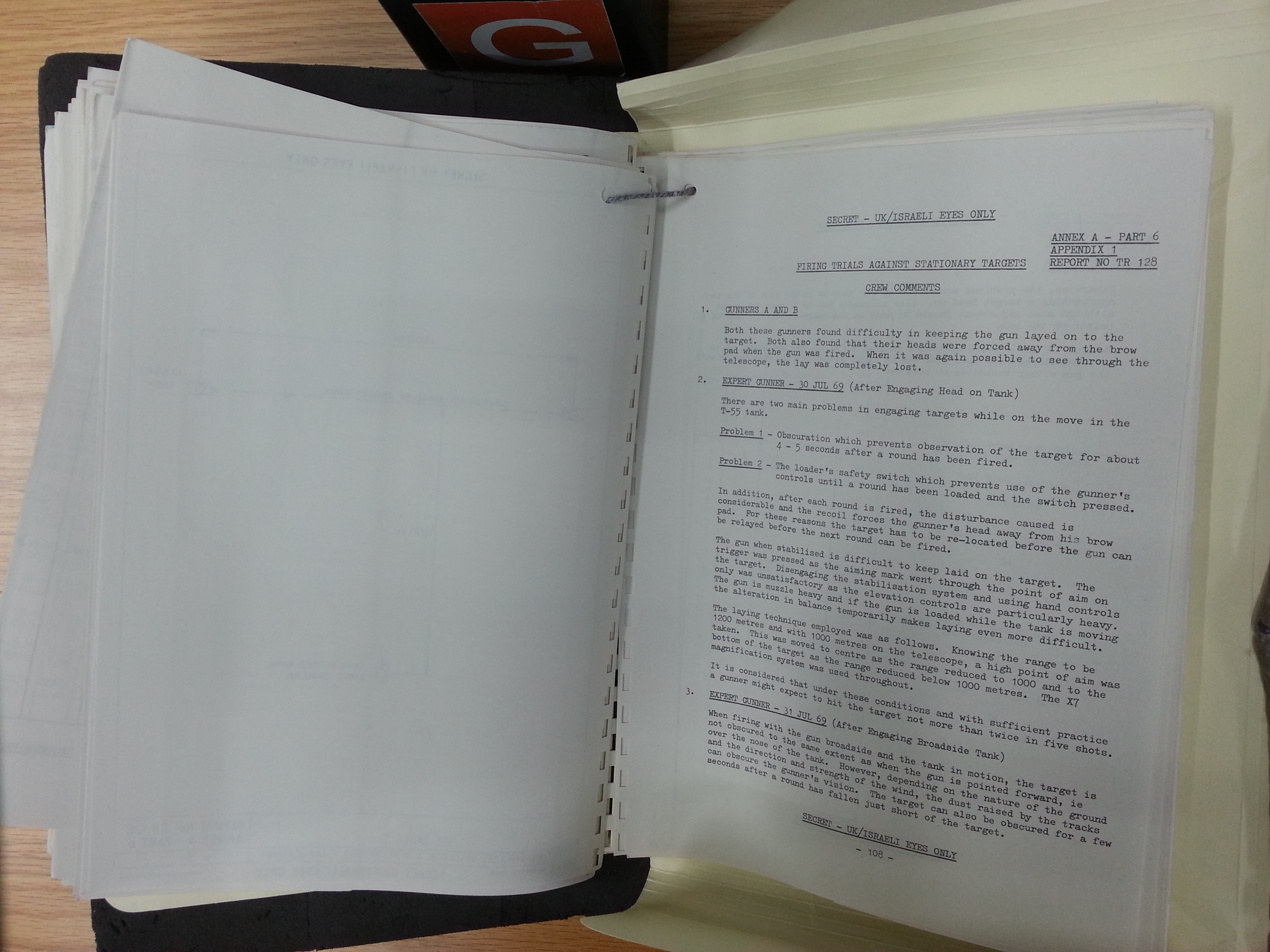
Out of 12 shots in phase A1, there was only one shot where the shell was off target in the horizontal plane. In phase A2, out of 11 shots, there was, again, only one shot where the shell was off target in the horizontal plane. In phase B1, out of 12 shots, we have two shots off target in the horizontal plane. In phase B2, out of 11 shots, we have one shot off target in the horizontal plane. All of the misses were due to the shot going high or low. It is very likely that in less dusty conditions, the T-55 could achieve much, much better accuracy. On a related note, the exclusive use of APDS ammunition for anti-tank purposes in the Centurion MK. 3 greatly contributed to good accuracy at all ranges, as the high velocity of APDS shells partially negated ranging errors.
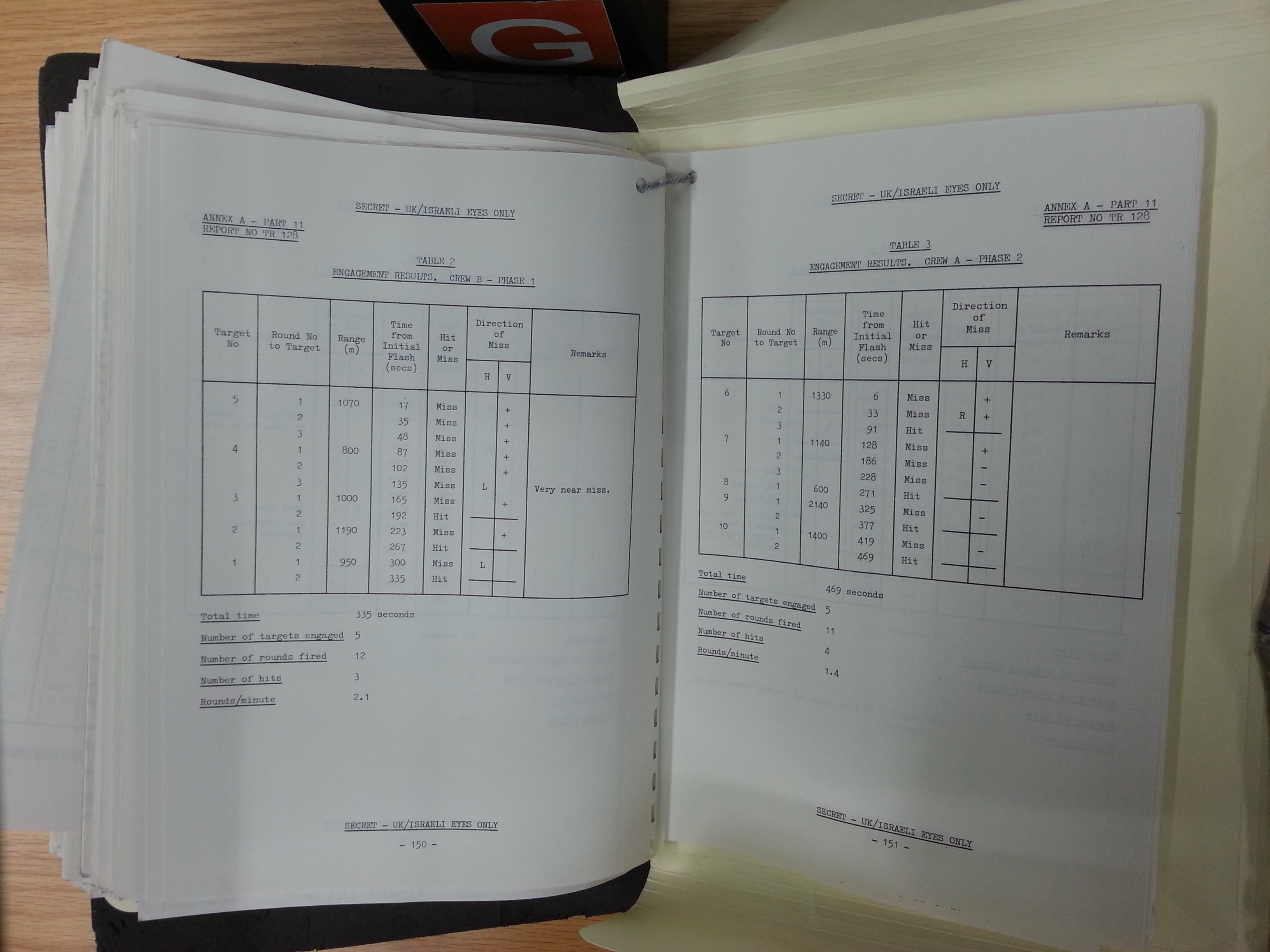
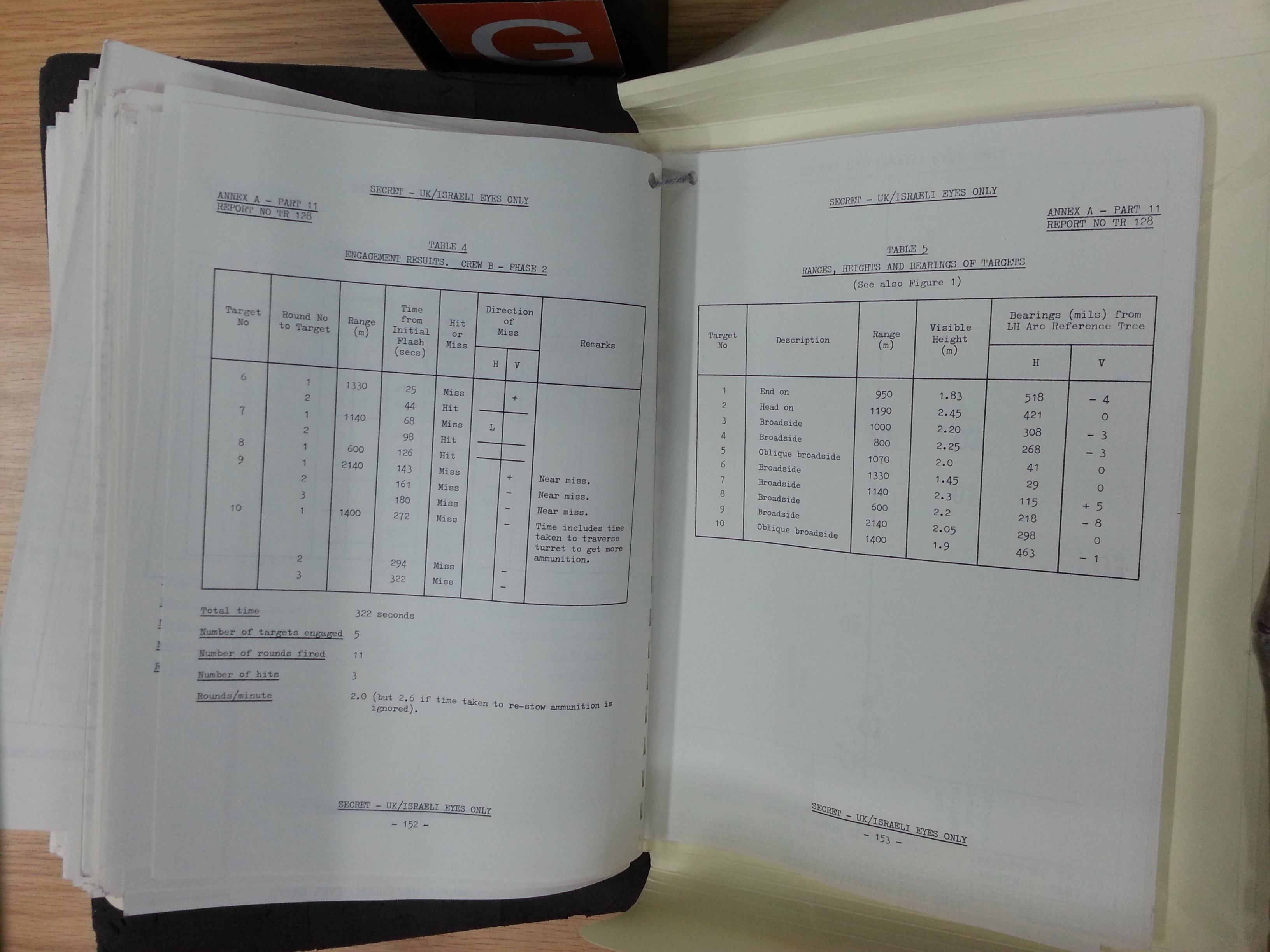
From a statistics standpoint, relying on this report to generalize the performance of all T-55 tanks in all conditions will be erroneous. Therefore, I ask the reader not to take any of this data at face value. This test cannot be used to represent the majority of T-55 tanks in real battle, and certainly not T-55 tanks in Europe, where environmental conditions are very different. Take this little analysis as supplementary knowledge.
D10-T (TG, T2, T2S)
At the time it entered service on the T-54 obr. 1947, the first serial T-54 model, the D10-T gun had a larger caliber than any other tank gun fielded on a medium tank from the late 1940's to the late 1950's, and more importantly, its ballistic performance was high enough to effectively combat the postwar medium tanks of the Western Allies and even pose a serious threat to heavy tanks like the M103 and Conqueror from their frontal arcs, albeit not from the direct front.
The total length of the gun is 5,608mm. The gun tube has a length of 5,350mm or 53.5 calibers, making the D10 an L/53.5 gun. It is worth noting that in the Soviet Army, the "L/" format is not used to denote lengths and there is no confusion between overall gun length and gun tube length. However, outside of the USSR, this format may be used for either overall gun lengths and gun tube lengths. For example, the German 8.8cm KwK 43 is officially listed as an L/71 gun. However, the master drawing for the KwK 43 shows that this is its full length, measured from the muzzle to the rear face of its breech, whereas the length of the gun tube alone is only 6,010mm, or 68.3 calibers.
There are 40 lands and grooves in the continuous twist rifling of the D10.
The maximum operating pressure of all D10 guns (rated based on AP rounds) is 3,000 kgf/sq.cm, or 294 MPa. This is comparable to the 90mm M36 and M41 guns used on the M47 and M48 Patton respectively. Data provided on page 2-37 of the engineering textbook "Interior Ballistics of Guns" produced by the United States Army Materiel Command, shows that the M318A1 APBC round fired from the M36 or M41 gun had a maximum operating pressure of 44,000 psi, or 303 MPa. However, being L/50 guns, the proportionately shorter barrels of the M36 and M41 hamstrung the potential gain in muzzle velocity, limiting it 914 m/s which is only 2.1% higher than the AP shells fired from a D10. On the other hand, the KwK 43 gun had the same maximum operating pressure of 3,000 kgf/sq.cm as the D10 according to its original design documentation, but due to its proportionately longer barrel, the muzzle velocity of its standard AP round exceeds that of the D10-T by a little over 100 m/s, translating to a difference of 11.7%.
The muzzle energy of the D10 series when firing its AP ammunition exceeded that of the KwK 43 by 20%, and naturally, the muzzle energy advantage of the D10 was even larger when compared to the M36 and M41 90mm guns. While the KwK 43 itself lost its relevance after the conclusion of WWII, it was still a good reference point for its particular class, as the domestic 85mm D-48 anti-tank gun and the British 20 pdr gun that was installed in various Centurion tank models since 1948 were both directly equivalent to the KwK 43 in ballistic performance.
To install the STP-1 stabilizer in a T-54 tank, a number of components had to be mounted to the underside of the gun. These were the hydraulic pump for the gun elevation drive, the gyro unit, the electrical transformer and the amplifier. The weight of these components made the gun rear-heavy. To solve this, the fume extractor was placed at the muzzle of the gun to act as a counterweight. A gun featuring all of these modifications was designated as the D10-TG. This gun was used by the T-54A. Later on, the gun was adapted to the "Tsyklon" dual-axis stabilization system, changing the designation to D10-T2S. This model featured only minor changes related to the slight differences in the installation of the stabilizer components under the gun breech.
The fume extractor is of a simple sheet metal construction. After a fired projectile has left the muzzle and the bore pressure plummets, the pressurized air contained in the fume extractor rushes out at a speed of approximately 500 m/s.
The width of the D10 gun breech is not known, but based on technical drawings, its width is identical to that of the R-112 radio installed in command variants of the T-54 series. The R-112 has a width of 422mm, so it is very likely that the D10 breech is around 420mm in width. For comparison, it is known that the width of the 122mm D-25T gun breech is 480mm and the width of the 8.8cm KwK 43 gun breech is 360mm.
In the T-54, the gun mount is slightly offset to the right. This offset appears to be intended to increase the working space for the commander and gunner as a significant amount of space is occupied by the equipment installed on the turret wall, whereas the loader's side of the turret is much less cluttered.


The rationale behind the decision to use a counterweight instead of simply retrofitting a fume extractor to the gun barrels of modernized tanks is unclear. There is no conceivable advantage whatsoever in omitting a fume extractor other than expediency. Nevertheless, the widespread implementation of fully stabilized guns and the addition of a night fighting capability was not a trivial matter. The increase in overall combat capabilities was a large boost for the vast tank fleet of the Soviet Army.
The production of D10-T, D10-TG and D10-T2S guns at the No. 9 plant in Sverdlovsk and the No.172 plant in Perm is documented in the table below.

The basic D10-T has a weight of 1,950 kg, including the gun cradle and armoured gun mask of a T-54 obr. 1949 or any model thereafter. Together with the gun cradle and recoil system, it weighs 1,430 kg. On the M60A1, the M68 together with its gun cradle weighs 1,410 kg and the combined weight of the entire gun assembly with the gun mantlet weighs 3,260 kg. On the Leopard 1, the L7A3 with the gun cradle and gun mantlet weighs 2,900 kg. Alone, the breech and gun tube assembly of the M68 and the L7 weigh 1,122 kg and 1,282 kg respectively, but data for the D10-T is not known. From this, it can be seen that the decision to abandon a turret design with a gun mantlet as on the T-54 obr. 1947 in favour of a much more compact gun mask led to a large reduction in the mass of the cannon assembly and thus reduced the work needed to elevate or depress the cannon.
To replace the barrel, it is necessary to lift the turret off the turret ring and pull the entire cannon assembly out the back. The turret is designed to tilt forward and stay propped open to make this easier to do in the field, but it is still by no means a quick procedure.

Here's a scene of this procedure being carried out in the field. The gun is being lifted by an engineering vehicle.

LOADER'S STATION

The T-54 is rather short compared to the T-34, so it is quite surprising that the actual available vertical space inside the T-54 is actually quite similar to its predecessor. Measuring from floor to turret ceiling, the fighting compartment of a T-34-85 was 1.56 meters in height, or 1.585 meters, or 1.55 m, depending on the source. The T-54, on the other hand, had a maximum internal height of 1.6 meters, even though the T-54 is 2.32 meters tall while the T-34-85 is 2.7 meters tall. This wizardry was only possible because a large part of the floor of the T-34-85 is taken up by an ammunition box which stows the majority of the tank's ammunition supply. Being tall enough to stow 85mm shells three rounds deep, the box takes up a considerable portion of the tank's available vertical space. As the floor of a T-54 only needed to accommodate the torsion bars and the false floor, it could have the same internal height as the taller T-34-85. The length and width of the loader's station in the T-54 was also improved over the T-34-85 thanks to the wider turret ring, although any improvement in loading speed were probably cancelled out by the much larger bulk and weight of the 100mm rounds.


The requirement for at least 1.6 meters of vertical space was not arbitrary. According to an article published in the April 2004 issue of the "Tekhnika i Vooruzhenie" magazine titled "Основы теории и история развития компоновки танка" (Fundamentals of the Theory and History of the Development of Tank Layouts) by Vasily Chobitok, the height of the loader's station should be between 1.6-1.7 m tall and 0.5 m wide with a space of 1 cubic meter to accommodate the loader.
The commander and gunner can sit down with a reasonably comfortable allotment of headroom, but 1.6 meters is not nearly enough to let a man of average height stand upright, even with the infamous practice of choosing smaller servicemen for tank crews. According to "Foundations of Design of Armament for Self Propelled Guns and Tanks", the average height of a man is stated to be 1.7 meters, so a loader of average height would have to conduct his duties from a seated or half-standing position. As the loader's protruding cupola breaks the turret's sloping profile, he has room to stand a little straighter directly when he is directly underneath the hatch, which, conveniently, is where he needs to be in order to ram rounds into it, but otherwise, the turret is far too low to allow the loader to work with a straightened back. The low ceiling at the front part of the turret is not a problem, as there is no ammunition there that is stored above waist level at the front of the turret. The loader's seat can be unhooked from the turret and relocated to a new position near the rear of the turret, so there are two possible seated positions from which the loader can perform his duties. As usual, the seat can be folded up and out of the way for the loader to stand and move around freely in his station, but the seat can also be unhooked and stowed away for extra space. There are two fire extinguishers at the rear of the turret, directly underneath one of the possible positions for the loader's seat. The loader is also furnished with an MK-4 periscope for general visibility. The periscope is installed in front of the loader's hatch and its aperture window is surrounded by an armoured collar that is a part of its rotating mount.


The loader is drilled to return to the MK.4 periscope immediately after loading and readying the cannon to help observe the fall of every shot and help search for targets until he is called to load another round by the commander. However, in practice, if the loader is not servicing the cannon, he is either getting another cartridge ready or rearranging the ammunition into the ready racks. The periscope is marginally useful when under threat of imminent contact with the enemy as it grants the tank an extra pair of eyes, but attempting to use a non-magnified periscope to help spot targets is usually a waste of time. The greatest value of the periscope is in the psychological benefit of giving the loader a sense of his surroundings. The extra lighting may be helpful as well, since the loader's station has only one dome light.
When an IR night sight was installed beginning in 1957, the addition of an IR spotlight on the starboard side of the turret above the coaxial machine gun port had the unfortunate side effect of blocking the loader's view in the 12 o'clock sector. As such, the loader's view was restricted to the right side of the turret only, which limits his ability to assist in finding targets and completely prevents him from observing the fall of shots. However, granting forward vision to the loader is often considered superfluous given that both the gunner and commander would be looking forward and observing the target anyway. As such, the loader would be more helpful if he was focused on scanning the right side of the turret instead.
AMMUNITION STOWAGE
The T-54 generally had a relatively small ammunition capacity, but not all T-54 models carry the same load of ammunition. All T-54 variants created between 1947 and 1958 could only carry a measly 34 rounds - nearly half that of tanks like the M46 and the Centurion. To be fair, this was compensated by the significantly higher explosive and anti-armour performance of each 100mm shell compared to a 90mm or an 84mm one, but only to a certain extent. By having fewer rounds at their disposal, a T-54 crew must be more mindful of ammunition expenditure as the probability of obtaining a direct hit was low due to the simple fire control system and the lack of high velocity ammunition such as APDS or APFSDS.
Unlike American and British tanks and post-war German tanks, the loader in the T-54 is situated on the right side of the turret, to the right of the gun. Because of this, he loads with his left hand and not his right hand, which is the dominant side for 90% of the world's population. This has been criticized as an ergonomic failing point as it is thought that this would tire out loaders at a quicker rate, but contrary to this perception, it was never noted to be an issue during combat or during field exercises in the T-54, or in other tanks with left-handed loading including WWII-era German tanks. It is possible that the lack of any quantifiable difference is because neither of the two loading layouts are without flaws. For left-handed loading, the loader holds the base of the cartridge with his left hand and holds the nose of the cartridge with his right arm or cradles it in his right arm. Since unitary cartridges are invariably nose-heavy, this would be most comfortable for the loader. The downside is that the loader must ram the cartridge into the cannon with his left hand. For right-handed loading, the loader holds the heavier end of the cartridge with his left hand and rams it into the cannon with his right hand.

Rather than left-handed or right-handed loading, the main impediments to a T-54 loader are the length and mass of the 100mm cartridges. This was the main downside to having a more powerful gun than the American Pattons and the British Centurions during the 1950's. The base diameter of each cartridge case is 147.32mm and the length is 692mm. Naturally, the armour-piercing rounds have shorter projectiles and are therefore shorter overall compared to HE-Frag and HEAT rounds, but generally speaking, the cartridges were quite long. For comparison, the cartridges for the 105mm L7 cannon were noticeably more compact, having a base diameter of 147.3mm and a case length of 617mm. The reduced length makes them easier to handle inside the confines of a tank.

A drawing of ammunition placement in a T-54 obr. 1951 is shown below. As the arrangement of ammunition in a T-54 obr. 1949 is practically identical to that of the more historically relevant T-54 obr. 1951, we will only be discussing the latter.
The 1951 upgrade that brought the new egg-shaped turret also brought improvements in the ammunition stowage scheme. Most notably, the bevelled turret rear was filled out, and this allowed an additional five rounds to be carried. You can see these racks in the photo below.

The five rounds are stowed crosswise, tip to tail. Three rounds are stowed pointing towards the commander, and two are stowed pointing to the loader. Unfortunately, the turret bustle is too shallow for the loader to avoid the recoil stroke of the cannon when retrieving ammunition from these racks. As such, it is dangerous to extract ammunition from these racks immediately after the cannon has been loaded as the loader will not know when the gunner will decide to fire, making it impractical to lapload using these racks. These racks are deleted from the T-54K command tank variant as the space is taken up by an additional R-112 radio.
An additional two rounds are stowed on the turret wall next to the loader. The rounds are mounted facing forward. This was a rather odd design decision, since this forces the loader to hold the base of the shell with his right hand and hold the nose end with his left, even though he can only ram the round in with his left hand. This prevents the loader from extracting the round, turning around and loading the round in one fluid stroke.
Four rounds are stowed with clips at shin level on the wall of the hull, on the loader's side. These are not very convenient to use in battle if the turret is pointing forward, but they are still easier to access than the ammunition located at the very back of the fighting compartment. If the turret is pointed to the right relative to the hull, these racks will be convenient for the loader as they would then be situated directly in front of him. The presence of these four rounds decreases the available width of floor space available to the loader by 147mm (the base diameter of a 100mm cartridge case) which is somewhat inconvenient.

Twenty rounds are stowed in a metal skeleton frame rack at the front of the hull. The loader must squat down to access these racks, but the way they are placed is extremely convenient for him. These racks are placed underneath the flat part of the hull ceiling due to geometric incompatibility with the sloping front part of the hull. Underneath the 60 degree slope of the upper glacis plate, and in front of the ammo racks, is a large triangular fuel tank.


Here it is being used in an FSA-operated T-54.

Finally, there is a single cartridge stowed on the floor of the hull next to the engine compartment bulkhead. Five 250-round ammunition boxes for the coaxial machine gun are stowed on the floor of the turret, underneath the cannon, and another two boxes are placed next to the front hull ammunition racks, next to the driver's seat.
The front hull racks are the most convenient to access. They are considered the primary ready racks of the tank. Because the supply of ready rounds in a T-54 were not stowed in the turret bustle racks but were instead stowed in the front hull racks, the spring-loaded support tray featured on the 85mm ZiS-S-53 cannon of the T-34-85 was not implemented on the D10-T. Instead, the horizontally-sliding breech block was more convenient. According to Stefan Kotsch, a former T-55 tank commander in the NVA, the tank crew is trained to point the hull toward an enemy tank in a tank duel. This presents the most heavily armoured zone of the tank to the enemy and naturally makes the front hull racks a convenient source of ammunition to the loader. However, there are additional nuances with the stowage scheme, one of them being that the rounds stowed at the bottom rows of the front hull racks would be harder to access than the rounds stowed at the top rows. The loader would need to take every opportunity available to rearrange the ammunition in such a way that they are convenient to access.
T-55

The T-55 introduced new front hull racks. Instead of a simple metal skeleton frame, these racks are conformal fuel tanks with slots for ammunition. Two rounds had to be sacrificed to make the arrangement work, slashing the total number of rounds stowed in the racks from 20 to 18. The rear hull fuel tank next to the engine compartment bulkhead was removed, but the new conformal fuel tank held 300 liters of diesel which offset removal of the rear hull fuel tank and increased the total fuel capacity of the tank by 100 liters, giving the tank an extended driving range. This was a considerable performance boost, especially since no additional useful internal space was used by the new special fuel tank and a volume of 200 liters was freed up by the removal of the rear hull fuel tank. This was enough space for an additional 11 rounds, so despite losing two slots in the front hull racks, the T-55 could carry 43 rounds of ammunition, which is 9 more rounds than previous T-54 models. Contrary to the commonly held belief that the removal of the bow machine gun enabled more ammunition to be stowed, the extra ammunition was not stowed anywhere near the removed bow machine gun, and the larger ammunition capacity of the T-55 had nothing to do with it at all.
The photo below shows the front hull ammunition racks in a special T-55 training demonstrator as seen from outside its imitation turret.

The rear hull ammunition racks can be seen below (some space is being used in a non-historical manner for assorted machine gun ammunition boxes).
 |
| Photo credit to Jim Chandler of the Warwickshire Armour Modellers |
It is not as easy to extricate ammunition from these racks as it is from the front hull racks or from the turret racks due to the horizontal arrangement of the ammunition and the presence of the large casing deflector extending almost to the turret ring. Therefore, these racks are considered non-ready racks for reserve ammunition. As these are not ready racks, they are usually filled with HE-Frag rounds as opposed to AP or HEAT rounds which would be stowed in the front hull racks. In the event that the loader must load the cannon when the turret is turned to the right, the rear hull racks will become much easier to access and would become his primary source of ammunition besides the rounds stowed in the turret.
It is possible for the loader to load the gun from a seated position. To do this comfortably, the seat should be placed in the rear position (facing forward) as this would allow the loader to easily access the two ammunition racks in the turret without any real difficulty. If the loader carries out his duties while seated, there would be no problems with the limited vertical height of the tank and even people of above average height would be able to load the gun with ease, but the limited amount of ammunition stowed in the turret makes it impractical for the loader to remain seated for the entire length of an engagement as he would need to access the ammunition in the hull to replenish the turret ready racks. If the situation is very dire, it would be faster to simply begin taking ammunition from the front hull racks once the turret racks are depleted. The GIF below shows a loader in a T-55A loading an APDS round while seated.

Experiences in various conflicts throughout the Cold War era have indicated that it is rare for a tank to expend more than 20 rounds of ammunition in a single engagement. Most often, the tank only needs to fire around a dozen rounds before the enemy is either destroyed or routed, keeping in mind that tanks do not operate alone - the firepower of a tank platoon or tank company is very high indeed, especially if tactical numerical superiority is achieved. This knowledge is reflected in the designs of tanks like the Pershing, M46, Centurion, and all the rest. In all of these tanks, and in the tanks that came after, ammunition stowage is divided into two types; ready and non-ready. Ready rounds are stowed in racks close to the loader, so that he can load as quickly as possible during battle. During the lulls between battles, the loader refills the ready racks with ammunition from the non-ready racks. The T-54 is no worse than any of its counterparts in this sense. The total number of rounds available in the ready racks in a T-54 is 29, whereas in the T-55, it is 27 rounds. As you may recall, another four rounds are stowed by the loader's feet at shin level, but they are not necessarily ready rounds in the strictest sense.
By comparison, a 20-pdr-armed Centurion has 28 ready rounds, according to a U.S Army report posted in abridged form by Nicholas "The Chieftain" Moran on the World of Tanks forum. There are 8 rounds in the ready racks in front of the loader and 20 more rounds in the voluminous front hull racks next to the driver. A 105mm-armed Centurion, on the other hand, has only 24 ready rounds in two racks close to the loader. The front hull racks hold 20 rounds as they did before, but now the ready racks in front of the hull only contain 4 rounds. These racks can be seen in the picture below. It can be seen that the ready racks partly obstruct the loader's access to the front hull racks, making it quite difficult to extract ammunition from those racks. The T-54 is more ergonomic in this respect.

The loader in a T-54 or T-55 is able to reach virtually all of the ammunition in the tank in both ready and non-ready racks, with the insignificant exception of the single cartridge stowed on the floor next to the gunner's seat. That single round is only useful when the turret is pointed directly behind the tank, which would prevent the loader from accessing any of the other hull ammunition racks. Obviously this is a rather inappropriate position for the tank to fight in, so the lack of any ammunition in the hull in such a scenario is not a disadvantage in any way. Furthermore, the low ammunition capacity of the T-54 is not a disadvantage where modern tank combat is concerned, such as in a meeting engagement. However, it can be an issue when meeting engagements become pursuits as the Soviet Army (hypothetically) blitzes across Europe. An adequate stream of supplies must always be maintained in order to keep up the pace of combat operations, and higher dependency on ammunition resupply may prevent some tank units from exploiting gaps in the enemy's defence in certain situations, although it is rather difficult to quantify the effects of lower ammunition capacities.
A popular myth is that the Soviet Army was ambivalent towards the T-54's relatively low ammunition capacity as it was believed that the tank would be sent to its doom in massed frontal attacks against dug-in NATO tanks and anti-tank weapons, so it only needed enough ammunition for one battle as entire tank fleets could be replaced within hours of its loss. However, this was never mentioned as official policy in any documents or in any Soviet military literature and it was certainly not part of the design requirements of the T-54, or any other Soviet tank for that matter. It must be said that huge losses were expected if the Soviet Army were ever to push into Europe, but that was simply the reality of warfare on such a large scale. The only reason why the T-54 has such a small stock of ammunition compared to NATO tanks is because of the paradox of having a large gun and a small tank at the same time.
RATE OF FIRE
Official Soviet documentation of tank crew norms (battle drills) specifies that loading an Object 137 and Object 155 (a T-54 and T-55 respectively) from the ready racks should take no more than 13 seconds. The "minimum" grade, which is the minimal passing grade, is 13 seconds, and the "good" grade is 11 seconds, while the "excellent" grade is 10 seconds. The standards for loading speed from the other ammunition stores are more lax; when loading from any ammunition rack other than the ready racks, the "minimum" grade is 15 seconds, the "good" grade is 13 seconds, and the "excellent" grade is 12 seconds. However, these numbers are contradicted by the rate of fire figures from the manuals.
The manual for the T-55A tank states that the combat rate of fire when firing from a standstill is seven rounds per minute and that the expected rate of fire when on the move is four rounds per minute. A 1969 manual for the T-54 (T-54 obr. 1951 with no stabilizer) gives the same numbers - the combat rate of fire is seven rounds per minute when firing from a standstill and four rounds per minute when firing on the move. Considering that the very first prototype of the T-54 had a rate of fire of only 5-6 rounds per minute, and that the T-44 using the ZiS-S-53 along with the T-34-85 could attain a rate of fire of 7-8 rounds per minute, it appears that the newer turret design of the T-54 provided a more conducive working environment for the loader.
Seven rounds per minute can be considered quite average for a medium tank, albeit one with a 100mm cannon. This amounts to a nominal sustained loading speed of 8.5 seconds per shot, assuming that acquiring a target and aiming at it takes less time than that. However, keep in mind that there is a technicality in the testing procedure. The Soviet measuring criteria calls for the use of all of the ammunition in the tank, not only the rounds from the ready racks. Drawing from only the most convenient ammunition racks and containers, the loader could achieve a higher burst rate of fire.
However, it should be noted that the combat rate of fire figures given in the manual definitely does not represent the loading speed of the loader. Qualitative analyses of gunnery trials at firing ranges showed that the loading speed does not exceed 7 seconds even when firing on the move, but the actual time between shots was longer due to other factors.
Reloading while the tank is on the move is more difficult in most variants of the T-54 compared to some other tanks due to the lack of a rotating turret floor, even if that was counter balanced by the rather sluggish spinning speed of the turret. Nevertheless, four aimed shots per minute is not a bad result when compared to other tanks, as you can see in the table below.

Older models of the T-54 that lack a stabilizer may have a lower rate of aimed fire when firing on the move as the time taken to acquire the target is much longer due to the need to halt or slow to a crawl in between shots as opposed to the T-54B and T-55 where the gunner can scan for targets while on the move.
AMMUNITION
According to the September issue of the 2008 edition of the "Техника и вооружение" magazine, the ammunition loadout of a typical Soviet T-54 and T-54A consists of 12 HE-Frag rounds, 4 "Shrapnel" rounds, 6 HEAT rounds and 12 AP rounds. The loadout of a Soviet T-55 and T-55A consists of 18 HE-Frag rounds, 4 "Shrapnel" rounds, 6 HEAT rounds and 15 AP rounds. The "Shrapnel" rounds most likely refer to 3USh-1 rounds with the 3Sh5 Flechette shell which contains 1,800 steel flechettes packed in a special casing which is fuzed to break apart during flight to release the flechettes. Due to the rarity of this round, most tanks probably substituted them with standard HE-Frag rounds.
The standard loadout of a Yugoslavian T-54 consists of 17 HE, 11 AP and 6 HEAT.
Two types of ammunition casings are available; D-412 steel cases, and Kh-415 brass cases. D-412 weighs 8.50 kg, whereas Kh-415 weighs 6.0 kg. Brass cases are mostly used for AP, APDS, APFSDS and HEAT ammunition to improve firing consistency, while steel cases are mostly used for HE-Frag ammunition as accuracy is slightly less important.
HE-Frag
A tank's target is not necessarily another tank. Most of the time, it isn't. And to that end, the average T-54 tends to have a larger number of HE-Frag ammunition in its loadout compared to its stock of anti-armour ammunition. Out of a total load of 34 rounds, a T-54 with a standard loadout can carry 10 HE rounds and 4 Frag rounds. When the ammunition capacity was increased to 43 rounds in the T-55 upgrade, the number of HE rounds increased to 18 rounds, but the number of Frag rounds remained the same. However, the implementation of HE-Frag rounds made Frag ammunition redundant. The number of HE-Frag rounds carried is the sum of HE and Frag rounds.
53-UOF-412
53-OF-412
The UOF-412 cartridge weighs a total of 30.2 kg. The OF-412 shell itself weighs 15.6 kg while the propellant charge contained within the steel or brass casing weighs 5.5kg. The explosive charge is TNT. Though it was far from unusual to have a TNT filler, more brisant and powerful fillers such as various mixtures of Amatol and A-IX-1 existed, and it is not explained in any literature why TNT continued to be used. Perhaps the most plausible explanation is that TNT was simply easier to cast and much cheaper and the expenditure of HE-Frag shells in times of war was expected to be so high that the cost efficiency of using TNT outweighed all of the drawbacks.
A 20 pdr. HE shell, for instance, weighs 7.838 kg and contains an explosive charge of 0.6 to 0.75 kg of TNT or Composition B (60% RDX, 40% TNT), depending on the exact model of shell. The OF-412, on the other hand, weighs twice as much at 15.6 kg and contains twice as much explosives with a 1.46 kg TNT explosive charge. For every 100mm HE round that the T-54 carried, a Centurion Mk. 3 would need two 20 pdr. ones to match it in payload. The raw kinetic energy of OF-412 shells is also much higher, not only because it is of a larger caliber and weighs twice as much but also has a higher muzzle velocity of 892 m/s compared to just 602 m/s for a 20 pdr. HE shell. This makes OF-412 very useful against hardened structures as it is capable of penetrating reinforced concrete pillboxes and heavy field fortifications when the PD fuze is set to the "HE" mode for delayed detonation. The range of the shell is also extended, making the T-54 more useful for indirect fire.
Muzzle Velocity: 892 m/s
Cartridge Mass: 30.2 kg
Projectile Mass: 15.6 kg
Explosive Charge Mass: 1.46 kg
OF-412 is is topped off with an RGM-6 point detonating (PD) fuse. The fuze is armed only by centrifugal forces, thus making it inert until it has been fired through a rifled gun barrel. There are two fuze settings with three possible firing methods. The superquick setting is marked with an "O" and the delayed setting is marked with a "З" (a Cyrillic "Z").

The superquick setting detonates the shell 0.027 seconds after impact and the delayed setting detonates the shell 0.063 seconds after impact. Superquick action guarantees reliable detonation in snowy or swampy ground, and delayed action gives a small time allowance for the shell to penetrate its target before detonating. Keeping the (waterproof) safety cap on the fuze has a delaying effect on the fuze (refer to the table above) and switches the round from the "Frag" mode to the "HE" mode. Setting the fuze is the loader's job, but it is the commander who dictates which setting is used. The variety of fuzing possibilities gives OF-412 an added degree of flexibility against targets of all types, meaning that the T-54 has to use fewer rounds overall compared to an early Centurion equipped with the 20 pdr. gun. This offsets the difference in ammunition quantity.
The delayed fuzing feature is beneficial to overall efficiency when the T-54 is used in an indirect fire role. When RGM-6 fuze is set to the delayed mode, OF-412 can be very useful against underground or dug-in positions, as the shell assumes an arcing ballistic trajectory when shooting at long range.
The fuze slot at the tip of the shell is also compatible with the V-429 variable delay fuse designed in the 60's. The V-429 fuse is point-detonating and armed by centrifugal forces, like RGM-6. The V-429 fuse differs from the V-429E (used in the 115mm U-5TS and 125mm D-81T), which is armed by the braking effect from the unfolding of the stabilizer fins of the shell. Like the RGM-6, the V-429 has two possible settings: superquick and delayed. The main advantages of the V-429 are that it is waterproof even without a waterproofed safety cap, and it has additional safety features to prevent the detonation of the shell even if the fuze is accidentally set off.
3UOF10
3OF32
3UOF10 is a more modern cartridge, incorporating the 3OF32 shell. This round was introduced in 1975. 3OF32 is designed to produce a more optimal pattern of fragmentation for increased casualties but also remain sturdy enough that it can penetrate reinforced concrete targets without breaking up. The 3OF32 shell is furnished with the V-429 fuze as standard.
Muzzle velocity: 900 m/s
Complete round mass: 30.36 kg
Propellant Charge Mass: 5.6 kg
Mass of Shell: 15.96 kg
Explosive Charge Mass: 1.7 kg
Explosive Type: A-IX-1
Number of Preformed Fragments and Their Mass:
With a mass of not less than 0.5 g: 1993
With a mass of 0.5 g to 2 g: 814
With a mass of 2 g to 15 g: 928
With a mass exceeding 15 g: 251
Statistical Average Mass of Fragments: 6.2 g (median is more important, but the statistic is not provided)
Velocity of Fragments and Ratio of Fragment Velocities:
100% - at least 1040 m/s
90% - 1060 m/s or more
80% - 1080 m/s or more
Interestingly, the 3OF32 was later used in the 2A70 low pressure cannon of the BMP-3. In that particular application, the low velocity of the shell further decreases the penetration of the shell into soil and snow, thus improving its fragmentation value, but the low velocity also reduced the energy of the shell and reduced the time allocation for it to penetrate hard obstacles, making it exceedingly unsuitable for bunker busting. It could, however, still be used to remove earth and log fortifications.
Armour Piercing (AP)
Throughout the 1950's, conventional full-caliber steel armour-piercing rounds were the only armour-piercing round available for the T-54, but even after reliable fin-stabilized HEAT shells became available in 1961, conventional full-caliber shells remained the standard ammunition type for dealing with tanks with the less numerous HEAT shell being reserved for more heavily armoured tanks. As a rule, this included heavy tanks like the M103 and the Conqueror or main battle tanks like the M60A1.
The typical example of this type of ammunition was cheap, reliably lethal, and tended to be more accurate than other types of ammunition. Out of a standard combat load of 34 rounds, a T-54 carried 12 armour piercing rounds and the remainder was taken up by HE-Frag rounds. The T-55 had an expanded ammunition capacity of 43 rounds and carried 15 armour piercing rounds in a standard combat load. When APDS officially became available in 1967, it replaced full caliber steel armour piercing ammunition entirely.
Throughout the military career of the T-54 series in the USSR and in most of its satellite states, AP shells were preferred over HEAT shells despite the obvious superiority of the latter in armour penetration power. When HEAT became available for the T-54, the ratio between AP and HEAT ammunition was 2:1, and when the T-55 tank was introduced with a larger ammunition capacity, it carried AP and HEAT ammunition in a 2.5:1 ratio. For example, according to ex-NVA tank commander Stefan Kotsch, a standard combat loadout for an NVA T-55 was comprised of 15 APDS rounds, 6 HEAT rounds and 22 HE-Frag rounds. It was the same in the Soviet Army.
The point blank range for BR-412B and BR-412D is 1,220 m for a target with a height of 2.7 meters, representing a NATO tank. This means that the gunner can set the sight at 1,220 m prior to an engagement, and when an enemy tank is spotted, the gunner simply aims for the center mass of the target. If the target is exactly 1,220 meters away, the shot will land on the turret ring. If the target is closer than 1,220 meters, the shot may land on the turret. If the target is slightly further than 1,220 meters, the shot may land on the hull. Either way, a hit is quite likely within the margin of error provided by the point blank distance. This is a faster method of engaging tank-type targets, and given the high threat posed by tanks, it is probably the preferred gunnery technique employed by most T-54 gunners. For precision gunnery, the range reading obtained by stadiametric rangefinding can be used to further enhance to probability of a hit.
53-UBR-412B
53-BR-412B
When the T-54 entered service in the Soviet Army, there were only two types of armour piercing ammunition available for it. BR-412 AP, and BR-412B APBC. BR-412B was formally introduced sometime around 1946 (apparently, it was already in production by early 1945, but not issued) as a modified version of BR-412, featuring a blunt nose and a ballistic cap to maintain an aerodynamically pointed nose. The shape of the blunt nose is similar to the older 57mm BR-271 APHE-T shot in that it has a small bump on the tip, but the bump is completely flattened and not rounded. As the ballistic properties of the two rounds were different, chiefly due to this ballistic cap, it made little sense to keep the worst of the pair, so the early incarnations of the T-54 were stocked entirely with BR-412B.
When fired from the D-10T, the probable deviation of BR-412B at a distance of 1 km is 0.3 meters in the horizontal axis and 0.3 meters in the vertical axis. At a distance of 2 km, the probable deviation is 0.5 meters in the horizontal axis and 0.6 meters in the vertical axis.
The quality of the steel is considered high, and the hardness is respectably high as well. The hardening of the shell progresses uniformly - hardest at the tip and areas close to the surfaces, and slightly softer at the center. In contrast, wartime production 76mm BR-354B for the ZiS-3 gun ranges from 47 points Rockwell C to 38 points (451 BHN to 351 BHN) at the tip alone. Such shells were prone to shattering on impact with hard armour. A hardness of at least 600 BHN at the tip - which BR-412B achieves in excess - is necessary to prevent this from happening. The BR-412B shell is fired from the D-10 series of guns at a chamber pressure of 294.2 MPa.
Below are two different analyses on different BR-412B samples. Both were done by the Ministry of Munitions in the U.K, but at different times. The one on the right was done in 1963 with ammunition from an unspecified recent conflict, and the one of the left was done in 1958 with ammunition taken from a captured Egyptian SU-100 from the Suez Crisis.


According to a U.S army document analyzing the Soviet 76mm BR-354B, it was mentioned that American armour piercing shots are generally hardened to approximately Rockwell C 60 (654 BHN) at the nose. By this metric, BR-412B can be considered on par with U.S ammunition.
With successful armour perforation, the lethality of BR-412B will be high due to the larger mass of the projectile compared to 85mm and 90mm guns firing the same type of shell, and it is further augmented by the 65-gram explosive charge of A-IX-2 at the base of the shell which ensures the complete destruction of the projectile after armour perforation. A British evaluation states that the detonation of the explosive charge has the effect of shattering the rearmost portion of the shell into five to six pieces as the shell exits the rear of an armour plate, supplementing the large spray of secondary projectile fragments and spall from the armour plate itself. As such, the cone of fragmentation is increased in size and a larger number of internal components will be hit. These five to six large chunks of hard steel may also produce even more fragmentation as they impact the interior walls of the target. In addition to that, the high energy of these chunks has a much greater chance of detonating ammunition inside the tank compared to smaller fragments. Contrary to how AP shells with a base charge are often perceived, the explosion will not send fragments in all 360 degrees like a grenade. It must be remembered that the walls surrounding the cavity containing the explosive charge are very thick - too thick to act as an effective fragmentation casing.
Nevertheless, the killing power of the shell is augmented to some extent by the percussive effect of the blast, which has greater power than that of an F-1 fragmentation grenade (which holds 60 grams of TNT), even though most of it is spent in cracking the base of the shell into several pieces. Confined inside the small spaces of a tank, the effect of the blast is magnified and the incendiary effect of A-IX-2 increases the chance of igniting fuel and ammunition, not to mention burning the crew and internal equipment. While 65 grams may not seem like much, A-IX-2 is a particularly useful explosive-incendiary compound because it contains aluminium as a fuel additive. A-IX-2 consists of 73% RDX, 23% aluminium powder, and 4% phlegmatizing wax. The aluminium powder content produces an incendiary effect, because aluminium powder is used as a fuel additive to increase the heat of combustion (Türker 2016, p. 426).
The high aluminium content in A-IX-2 means that there will be some unburnt aluminium powder dispersed into the surrounding air, where it will burn at reduced rate due to the reduced oxygen level in the air (and also in the RDX itself, as RDX is oxygen deficient) and due to the increased concentration of gaseous byproducts from the explosion. Augmenting this effect is the fact that the burning of aluminium generates an alumina (aluminium oxide) coating over the surface of the aluminium particles. The alumina acts as an insulation layer, thus delaying the burning of the aluminium itself so that the efficiency of combustion is reduced. This has the effect of extending the duration of combustion and thus increasing the explosive impulse, extending the release of heat energy, increasing the explosive impulse, extending the radius of the incendiary effect, and increasing the probability of igniting other flammables in the vicinity of the explosion. Because of these factors, all HE-I shells for aviation cannons and APHE shells developed in the USSR after 1940 used A-IX-2 exclusively. On the other hand, medium to large caliber HE-Frag shells usually had an A-IX-1 or Trotyl filler, presumably for cost reasons.
Muzzle velocity: 895 m/s
Mass of Complete Round: 30.1 kg
Projectile Mass: 15.88 kg
Mass of Explosive Charge: 0.065 kg
Explosive Charge Type: A-IX-2
Chamber Pressure: 294.2 MPa
According to Yugoslavian tests, BR-412B could only defeat the front turret armour of a T-54A at a distance of 500 meters. This means (indirectly) that BR-412B can perforate 200mm of cast steel armour of medium hardness set at an angle of 0-30 degrees at 500 meters. This is well within the figures listed below.
Penetration at 0 Yards:
164mm at 30°
133mm at 45°
96mm at 60°
59mm at 70°
Penetration at 1,000 Yards:
140mm at 30°
115mm at 45°
82-85mm at 60°
51mm at 70°
Source: British test report: DEFE 15/1107 "The Performance of Russian SU 100 APHE/T Shot UBR-412B Against Armour Plate"
All values are for a 50% chance of penetration.
The British use the V50 standard instead of the Soviet/Russian V80 standard. If the document were Russian, the distance where the shell would be able to penetrate the armour of the tank would be listed as shorter. Besides that, the criteria for what constitutes armour penetration differs substantially from the Russian criteria. The British and American criteria dictates that at least 50% of the projectile mass must end up on the other side of the armour plate per a certain velocity, or in more practical terms, a certain distance (as the function of distance is the derivative of velocity). This forms the basis of the V50 standard. The Russian criteria as manifested in most firing tables dictates that at least 75% of projectile mass must be found on the other side of the armour plate. In actual certification testing, though, an 80% standard is used. This is responsible for the differences in penetration values of Russian ammunition in both military and civilian literature.
These figures are backed up by this page of the report:

Each vertical divider on the chart represents 250 meters.
All values are in V50 standard. The hardness of the target plates is listed below.

Penetration at 0°:
100 m: 235mm
250 m: 226mm
500 m: 211mm
750 m: 197mm
1000 m: 185mm
1250 m: 172mm
1500 m: 161mm
2000 m: 141mm
2500 m: 123mm
3000 m: 108mm
(WWII Ballistics: Armour and Gunnery, corroborated with Janes' Ammunition Handbook)
As usual, the ballistic arc of the shell is not significant enough to affect armour penetration on sloped targets by any significant amount. According to Soviet firing tables reproduced in the CIA report "Technical Information on the 100-mm Gun and Other Armament on the T-54 Tank" from 1960, the angle of descent of BR-412B and BR-412D is 0.4 degrees at a distance of 1 km and 1 degree at 2 km.
In terms of penetration power and post-penetration lethality, BR-412B is nominally superior to 90mm M318A1 APCBC. However, the T-54 did not have access to "premium" ammunition like M304 HVAP, though 100mm BR-412P HVAP ammunition was built in some small quantities and was considered for full issuance. Ultimately, regular steel rounds were considered adequate and BR-412P never saw the light of day. For situations where steel AP was inadequate, multipurpose HEAT ammunition could do the job better than tungsten cored HVAP ammunition while simultaneously offering a secondary anti-personnel function thanks to its explosive charge and thick steel casing.
Once full armour perforation is achieved, the results are utterly devastating. (The photo on the left is actually from a BR-412D penetration, but the effect is much the same).


As a rule of thumb, the entry channel in a thick armour plate is always larger than the actual caliber of the shell and the exit channel is typically equally large if not more so. A blast of armour fragments is ejected at extremely high speed into the tank, followed by shards of the shell, followed by the shell itself which may or may not be intact. If intact, the explosive filling at the base of the shell detonates and fragments the steel body, creating additional fragmentation and increasing the spray cone angle of fragmentation after clearing the armour plate. The MD-8 fuse embedded in the rear of the shell has a delay to ensure that the explosive charge detonates a certain distance inside the tank past the armour, making it more deadly than if it detonated immediately after perforating the armour plate, or during the penetration phase inside the armour plate.
Although it was originally intended for defeating increasingly thick German tank armour near the end of the Second World War, the intended targets for the BR-412B shell quickly changed to American tanks. The M26 Pershing, and by extension the M46, both have a 100mm-thick cast steel upper glacis angled at 46 degrees. Factoring in the lower efficiency of cast armour compared to rolled armour and the information from the British tests, it should be vulnerable to BR-412B at a distance in excess of 1.5 km. As for the M47, Yugoslavian ballistic testing found that the 100mm cast steel upper glacis with a slope of 60 degrees can be perforated by BR-412B at a distance of 750 meters. This would not have been an acceptable result by WWII standards as average tank combat distance was between 200-800 meters, but as tank optics improved, this became rather close for comfort. Nevertheless, the T-54 still nominally outranges the M47.
According to page 25 of WWII Ballistics: Armour and Gunnery, a 100mm cast armour plate within the 220-300 BHN hardness range is 93% as effective as rolled armour with a hardness of 240 BHN at a 0 degree impact angle against 100mm armour piercing projectiles. The book does not list the relative efficiency of cast armour when it is sloped, but this information agrees with the results of the Yugoslavian tests, implying that the efficiency does not change significantly with the angle of the plate.
The M47 became the mainstay of many European armies including the West German Bundeswehr, but the improved M48 was the backbone of the U.S Army for most of the Cold War. The upper glacis of the M48 is cast steel, 110mm thick sloped at 60 degrees, which is more somewhat formidable than the upper glacis of the M47. 110mm of cast steel should be equivalent to around 102mm of rolled steel, making the upper glacis of the M48 approximately on par with the T-54 itself. A detailed report on the performance of BR-412B against the M48 is detailed in this Tank Archives post, courtesy of Peter Samsonov. The original 1958 report is titled "Броневая Защита Американского Среднего Танка М-48". Soviet testing revealed that BR-412B was not capable of penetrating the upper glacis of the M48 even at point blank range, which should not be surprising as the Yugo test report mentions that BR-412B was not capable of perforating the upper glacis of a T-54A. However, the lower glacis of the M48 could be perforated at 2,500 meters. It is interesting to note that the Soviet report concluded that BR-412B needed an impact velocity of 940 m/s to defeat the upper glacis armour of the M48, which is substantially higher than the muzzle velocity achieved by firing BR-412B out of a D-10 or a BS-3 gun. Defeating the upper and lower side hull armour of the M48 from a side angle of 30 degrees (from the longitudinal axis of the tank) is possible from a distance of 500 meters.
The turret of the M48 is weaker than the upper glacis - mostly because it is not nearly as sloped as the upper glacis - but it is still very well rounded and quite formidable. The thickness of the front turret face at the gun mantlet region varies from 178mm to 100mm, with sloping that ranges from 14 degrees at the very bottom edge of the turret where it is thickest to 56 degrees near the turret roof, where it is much thinner, but no matter what the thickness or slope is, the thickness on the front turret face invariably measures up to exactly 7 inches, or 178mm. The thickness reduces considerably beyond the immediate front turret face, but this is somewhat compensated by additional horizontal slope, although the final LOS thickness is still less than the front turret face. By referring to the penetration values given earlier, we can see that the front turret face cannot be considered well protected against BR-412B.

The gun shield overlaps the front turret face slightly, but the area of overlap is very small and the gun shield itself is negligibly thin. The most significant portion of the gun shield is 110mm thick, sloped at 30 degrees, which comes out to 127mm in LOS thickness. This should be vulnerable to BR-412B at a distance of more than 1,200 meters.
Overall, BR-412B should be able to perforate the area near the base of the turret at distances in excess of 1,250 meters, and the area near the roof should be highly vulnerable at a distance of at least 800 meters. This was inexcusable, since BR-412B was by no means new by the time the M48 entered service. For this reason, the Soviet report "Броневая Защита Американского Среднего Танка М-48" concluded that 100mm rounds are generally effective against the M48, despite the inability to defeat the upper glacis armour. However, better ammunition in the form of BR-412D became available at the same time that the M48 entered service in the U.S Army.
53-UBR-412D
53-BR-412D
Steel shell with a soft steel armour piercing cap. This shell formally replaced the BR-412B as the standard anti-armour round in 1953, but it came as early as 1951 as an component of the loadout of the T-54 obr. 1951 (the brand new TSh2-22 sight for the T-54 obr. 1951 had a range scale for BR-412D). Both BR-412B and BR-412D continued to be used side by side for some time, so in actuality, BR-412D supplanted the BR-412B rather than replaced it outright in Soviet service. Some former Soviet satellite states were still using BR-412B into the 2,000's until they eventually scrapped their T-54 tanks completely.

The armour piercing cap prevents the shell from breaking up when it impacts thick steel plate at high velocities. Controlled fracturing of the nose of the shell is beneficial towards penetration on sloped targets, but shattering of the shell will neutralize it completely. This shell is superior to the BR-412B on both low and high obliquity targets, but the difference is most noticeable at low obliquity. In page 10 of "Mechanisms of Armour Penetration" by Niko Holkko, it is shown that uncapped APBC and AP shells are more effective on thin plates (0.4 calibers) at all angles compared to APC and APCBC shells, but the inverse is true when the plate thickness reaches 0.45 calibers and above. On a thick plate (1.3 calibers), APC and APCBC rounds vastly outperform APBC at 60 degrees obliquity. In practical terms, the superior penetration on thick sloped armour makes BR-412D a favourable choice when engaging modern tanks of the era such as the M47 and M48.
Muzzle Velocity: 887 m/s
Complete Mass of Round: 30.4 kg
Projectile Mass: 15.88 kg
Mass of Explosive Charge: 0.061 kg
Explosive Charge Type: A-IX-2
Chamber Pressure: 294.2 MPa
Point-blank ranges:
For a target height of 2.0 m - 1,070 m
For a target height of 2.7 m - 1,220 m
For a target height of 3.0 m - 1,270 m
For armour penetration, Zaloga gives these figures (Link):
Penetration at 0°:
100 m: 200mm
500 m: 185mm
1000 m: 170mm
1500 m: 155mm
2000 m: 125mm
Penetration at 30°:
100 m: 150mm
500 m: 140mm
1000 m: 130mm
1500 m: 120mm
2000 m: 100mm
These values are in Soviet standard. Soviet target plates had a hardness of between 250 to 350 BHN.
Penetration at 0°:
100 m: 250mm
1.0 km: 185mm
1.5 km: 170mm
(Source unknown)
The CIA report "Technical Information on the 100-mm Gun and Other Armament on the T-54 Tank" has this penetration table for the BR-412D:

Comparing these figures to Zaloga's, we can see a significant discrepancy. The CIA's figures are much higher, especially when we go up to and beyond 2,000 meters. At 500 m and 1,000 m, the CIA's figures are 10mm higher for a 30-degree impact and 15mm higher for a 0 degree impact. At 2,000 meters, the CIA's figures are 20mm (!) higher for a 30-degree impact and a 30mm (!) higher for a 0-degree impact. The figures in the report are apparently taken from Soviet documents.
According to these figures, BR-412D should be more than capable of perforating the front hull armour of a Leopard 1 at distances in excess of 1,500 meters. The Panther's 82mm upper glacis sloped at 55 degrees was found to be penetrable at a distance of 1,500 meters. As for the M48, the BR-412D should have an effective range of several hundred meters more than the BR-412B when attacking the turret, but the most noticeable advantage is that BR-412D should be able to perforate the upper glacis of the M48 at a distance of around 500 meters, based on the difference in slope modifiers.
3UBM8
3BM8


3BM8 is an APDS shell for the D-10T that officially entered service in 1967. However, mass production began some years prior to 1967, and the modified TSh2B-32P sight with markings for APDS rounds was introduced in 1965.
The development of Soviet anti-tank munitions is highly unusual in that APFSDS rounds entered service before APDS rounds whereas foreign nations invariably put APDS rounds into service before upgrading to APFSDS ammunition later on. The 3BM8 round specifically was part of a unified development effort that led to the introduction of APDS rounds for the 122mm D-25T and M62-T2S guns for T-10 heavy tanks. If the 100mm D-54 gun were to enter service in the late 1950's instead of the 115mm U-5TS smoothbore gun, it would have been supplied with an APDS round almost identical to 3BM8.
3BM8 had good performance on vertical plate, possibly as good as 105mm L28 APDS, but its effectiveness on heavily sloped plate was largely unremarkable, although there are certain nuances that can be attributed to its design. Unlike the 105mm L28 APDS series, the penetration depth of 3BM8 into armour plate does not have a linear relationship with the slope of the late.
When comparing 3BM8 to the 20 pdr. MK.3 and the 105mm L28, it can be seen that the core of the 3BM8 and the MK.3 is an ogive whereas the L28 has a blunt tip. This is responsible for the better penetration of L28 on sloped armour plate at the expense of some penetration performance on flat armour plate. However, it is worth noting that problems with L28 were encountered during combat, prompting the development of tilting caps.
As a side note, MK. 3 and the more advanced L28 are similar in that they both have an unsecured cap. The MK.3 projectile has a small blunt steel cap (possibly non-ballistic in function, as it is referred to as a spacer) and the L28 has a conical tungsten carbide cap. For 3BM8, an extraordinarily thick section of low hardness alloy steel in front of the core acts as the armour piercing cap, and the hollow tip of the structure is partially filled with some lightweight metal (probably aluminium) to act as a windscreen. Although it appears to be less elegant than the solution used in the L28 round, the large steel cap may be highly beneficial against simple dual-layered spaced armour as the cap cannot be easily removed by a thin spaced plate: the thickness of the cap is too high to be eroded by a thin spaced plate, and the firm integration of the cap as a part of the jacket for the core makes it more difficult to dislocate the cap or deflect it away from the core after passing through a spaced plate. This is an interesting perspective to consider, as the deficiencies of L28 on thin spaced armour was well known - a thin 10mm steel plate could not only remove the tungsten armour piercing cap but also shatter the tungsten carbide core, making it ineffective on any subsequent plates. The extraordinarily thick steel cap of 3BM8 may have been designed to alleviate this issue, and this is explored later in the article.

Besides that, the tungsten carbide core in 3BM8 is smaller and lighter than the one in MK. 3 and also lighter to the one in the L28, although the diameter is slightly larger. From left to right: 3BM8, MK.3, L28 with tilting cap. Earlier L28 variants had a core with a blunt tip instead of a hemispherical tip. The hemispherical tip allowed the cap to slide against the tip of the core, which would not have been possible with a blunt tip.


The same design of core contained within the 3BM8 projectile is shared by the 122mm 3BM11. The development of the 3BM8 is directly related to the 3BM11, as they were both born out of the same set of requirements. The shared heritage can be seen in their identical designs. 3BM11 appears to be larger than 3BM8, but that is mostly due to an increase in the thickness of the steel sheath over the core, leading to an increase in the overall diameter of the projectile but not in the diameter in the core itself. The sabot has a distinctly larger diameter. 3BM11 penetrates 320mm at 0 degrees and 110mm at 60 degrees, but this is purely due to the higher power of the cannon that fires it.


Muzzle Velocity: 1,415 m/s
Maximum Chamber Pressure: 3,000 kg/sq.cm
Mass of Complete Round: 20.9 kg
Projectile Length (incl. sabot): 240mm
Projectile Mass (incl. sabot): 5.7 kg
Subcaliber Projectile Diameter: 55mm
Subcaliber Projectile Length: 223mm
Subcaliber Projectile Mass: 4.13 kg
Source for dimensions: (Link)
Core Material: Tungsten carbide
Core Diameter: 50mm
Core Length: 120mm
Core Mass: 2.82 kg
Point blank ranges:
For a target height of 2.0 m - 1,680 m
For a target height of 2.7 m - 1,930 m
For a target height of 3.0 m - 2,020 m
All information from official instructional booklet on 3BM8 and 3BK5.
As seen in the viewfinder of the TShSM-32P sight, APDS ammunition was a huge improvement over the old full-caliber steel AP rounds. According to V. A. Grigoryan in "Защита танков", 3BM8 has a muzzle velocity of 1,415 m/s and a velocity of 1,202 m/s at 2 km. The rate of velocity loss from this data amounts to 106.5 m/s per kilometer, and the deceleration is -142 m/s^2. In comparison, the 105mm L28 APDS round with a muzzle velocity of 1,478 m/s is reported to have a velocity of 1,381 m/s at 1 kilometer, implying a rate of velocity loss of 97 m/s per kilometer. Given that the rate of velocity decay increases with distance, the aerodynamic performance of 3BM8 can be considered functionally identical to L28 and also to the L36 and L52 which share the same ballistic shape as L28.
The tables below are taken from page 205 of "Частные Вопросы Конечной Баллистики" (Particular Questions of Terminal Ballistics) published by Bauman Moscow State Technical University on behalf of NII Stali. The first column from the left indicates that 3BM8 is the tested projectile and the next three columns from the left list the spaced armour configurations: b1 and b2 denote the thickness of the first and second plates in millimeters, and L denotes the size of the air gap in millimeters. The fourth column from the right lists the velocity limit of 3BM8 for the described spaced armour configuration, and the third column from the right lists the velocity limit for a monolithic plate of the same thickness in steel (b1 + b2). The difference in the velocity limit is listed in the second column from the right. The first column on the right shows the difference in the velocity limits between the spaced armour configuration and a monolithic RHA plate in percentage points, and also represents the improvement in mass efficiency. For example, in the table below for spaced armour targets at a 0 degree obliquity, 3BM8 can defeat a 150-300-90 spaced armour design angled at 0 degrees at an impact velocity of 1,215 m/s, whereas a monolithic 240mm plate (150 + 90) can be defeated at a velocity of 1,050 m/s. The difference in velocity limits amounts to 15.7%, showing that the spaced armour is 15.7% more effective than a monolithic armour plate of the same mass. In terms of distance, a velocity of 1,215 m/s corresponds to a distance of 2 km and a velocity of 1,050 m/s roughly corresponds to a distance of 3.4 km.

The table below shows the velocity limit of 3BM8 on similar spaced targets but at an angle of 30 degrees. From the table below, it can be seen that the effect of increasing the thickness of the spaced plate from 20mm to 50mm to 90mm while maintaining the same amount of spacing and the same 150mm RHA back plate causes a negligible increase in the effectiveness of the spaced armour in terms of mass efficiency: only from 21.5% to 22.5%. Of course, in real terms, the use of a 90mm front plate makes the sloped spaced armour effectively immune to 3BM8 at point blank range whereas a monolithic plate with a thickness of 240mm (90 + 150) under the same conditions could be defeated at a velocity limit of 1,160 m/s, which translates to a distance of roughly 2.5 kilometers. Overall, it can be seen that the increasing the thickness of the back plate of a spaced armour design has a much larger effect than increasing the thickness of the front plate for spaced armour sloped at 30 degrees.

This analysis is reinforced by shooting results at 30 degree targets with 122mm 3BM11, which has the same basic projectile design as 3BM8 and only differs in the increased muzzle velocity when fired out of a 122mm cannon and the shape of the steel jacket around the tungsten carbide core. As seen in the table, the use of a 200mm back plate with a spaced 20mm front plate and a 350mm air gap results in a 42.1% increase in mass efficiency. The use of a spaced 10mm front plate with an 80mm air gap and a 140mm back plate yields practically no improvement in mass efficiency whatsoever, which is the opposite of the expected result for an L28 round. Experiments conducted with L28A1 imitators and L28A1 scale models also showed that the design was highly sensitive to spaced armour. It was shown that a 20-300-50 spaced armour design sloped at 30 degrees yielded a 62.8% increase in mass efficiency, which is quite large compared to the 14.3% increase when 3BM8 was shot at the same target. VK-12 tungsten carbide was used for the L28A1 imitators. VK-12 has a 12% cobalt binder instead of the normal 8% nickel binder of VN-8.

The table below shows the velocity limits of 3BM8 for a target angled at 60 degrees in the same format. The data below is obviously quite significant in determining the capabilities of 3BM8 against simple spaced armour such as the type found on upgraded Leopard 1 tanks, but useful data on the velocity limits for monolithic plates is also given. According to the table, the velocity limit for a 100mm monolithic plate (from the table: 20 + 80) is 1,220 m/s, corresponding to a target distance of just under 2 km. Also, the velocity limit for a monolithic 85mm plate (from 40 + 45) is 1,125 m/s which corresponds to a distance of between 2.5-3.0 km, and the velocity limit for a monolithic 90mm plate (10 + 80) is 1,160 m/s, corresponding to a distance of between 2.0-2.5 km. From this data, the 80mm penetration figure for a 60 degree target at 2 km appears to be a guaranteed or a minimum penetration figure and the actual achievable penetration can be much higher at the same distances.
Regarding the optimization of the spaced armour designs, it can be seen that the most effective configuration in real terms is the 20-300-80 array, which can only be defeated from near-point blank range (velocity limit of 1,400 m/s). However, the most efficient configuration is the 20-300-45 array, which had a 21.1% mass efficiency advantage over a monolithic armour plate of the same mass. However, the 20-300-45 armour could be defeated at a velocity limit of 1,150 m/s and a 65mm plate (20 + 45) could be defeated at a velocity limit of 950 m/s, corresponding to distances of roughly 2.5 km and 4.4 km respectively.

The graph below illustrates the change in velocity limit for changes in the thicknesses of the first and second spaced plates. The thickness of the first plate is alternatively expressed in terms of the ratio of the thickness to the diameter of the tungsten carbide core.

Although higher than the more commonly cited figure of 80mm at 60 degrees at 2 kilometers, the penetration figures for a 60 degree plate from "Particular Questions of Terminal Ballistics" still fall short of the claimed performance of the 105mm L52 APDS round from the early 70's (reportedly entered service in 1973 in the U.K, 1974 in the U.S in the form of M728), which is comprised of a tungsten alloy core with a steel armour piercing cap and can reportedly perforate 120mm RHA at 60 degrees at a distance of 1,830 meters (according to a marketing brochure) and penetrate 250mm RHA at 0 degrees at 1,000 meters (according to Janes). The use of softer but much tougher tungsten alloy core in the L52 instead of a tungsten carbide core with exceptionally high hardness but low toughness was aimed at improving the performance of the round on non-monolithic targets, particularly simple dual-layered spaced targets. An increase in performance on oblique targets was also obtained. This improved performance came at the cost of reduced performance on monolithic RHA targets at a flat angle, which is reflected in the penetration figures mentioned earlier - 250mm RHA at 0 degrees at 1 km for L52, and 290mm RHA at 0 degrees at 2 km for 3BM8.
The merits of the increased performance on sloped and non-monolithic targets are self-evident. At the time, all of the known Soviet medium and heavy threats incorporated heavily sloped armour and there was no indication that Soviet armour designs would trend towards thick and flat homogeneous steel plating in the near future. Similarly, the newest NATO tanks as of 1967 - namely the M60A1 and the Chieftain - also relied heavily on the complex oblique ballistic shaping of their cast hulls and turrets. The design of the 3BM8 penetrator was unsuited for such targets, which is indicative of a large technological gap between the USSR and the West. That said, the side armour of any NATO tank could be defeated by 3BM8 from a high angle of incidence.
Aside from that, it is clear that 3BM8 boasts greatly improved penetration power compared to the outdated BR-412B and BR-412D rounds at all angles of obliquity, but it could also be argued that the primary benefit of the APDS round was the enhanced probability of achieving a hit on faraway targets and especially moving targets. This advantage arguably carries more weight than the increased penetration power, as despite the increased armour piercing performance, the challenge of defeating the frontal armour of contemporary tanks like the M60A1 and Chieftain would be practically insurmountable at long ranges. If the T-54/55 hoped to defeat these formidable foes from the front in the 1961-1971 time frame, it could only do so with HEAT ammunition. This situation contradicts the common Western narrative that the T-62 was made redundant by the introduction of the 3BM8 round. In truth, the T-54 series only gained the ability to counter NATO's new main battle tanks when it began receiving APFSDS ammunition in 1972.

The 3UBM7 round contained the 3BM19 projectile with a steel penetrator. It was designed as an all-steel alternative to the 3UBM8 round with the 3BM20 projectile that contained tungsten carbide. The impetus behind the creation of this round is unclear, but it is unlikely that it was created solely for training purposes as it is listed as a combat round.
The shape of the projectile was identical to 3BM20 and the ballistic properties of the cartridge was identical to 3BM20. Although the penetrators of the two projectiles were different, both used the same sabot and stabilizer fin assembly with the same tracer. Compared to the 3BM8 projectile that it replaced, the 3BM19 featured only a slightly higher muzzle velocity of 1,430 m/s, but its kinetic energy was not higher because the weight of the projectile decreased slightly to 4.06 kg. It is therefore not surprising that its ballistic characteristics were very similar to the APDS round it replaced. Having a point blank range of 1,690 meters against a target with a height of two meters, and a point blank range of 2,040 meters against a target with a height of three meters, the trajectory of 3BM20 was only negligibly flatter than 3BM8.
The three-piece steel sabot designed for the 3BM19 differed significantly from the steel "ring" type sabot for the APFSDS rounds used in the smoothbore 115mm and 125mm guns at the time, and needless to say, it was completely different from the "cup" type sabot of 3BM8. Despite the shorter length of the three-piece sabot and the use of the stabilizer fins of the projectile as contact points, its weight was similar to the sabot of the 3BM8 projectile. Moreover, the penalty for the use of large bore-riding stabilizer fins was high aerodynamic drag. The D-10 gun was evidently not suitable for the extremely light "ring" type sabots used by the 100mm T-12, 115mm U-5TS and 125mm D-81 smoothbore guns.
At the time, the use of the stabilizer fins as contact points between the projectile and the bore was a universal feature of all Soviet APFSDS rounds but the particular design of the three-piece sabot was unique to the D-10 family of guns due to the presence of rifling, so naturally, it featured some measures to ensure that round could operate normally with rifling. The main design feature to neutralize the effect of the rifling was the copper driving band which was only loosely connected to the sabot so that the friction between the band and the sabot would be very limited. This allowed the driving band to act as a slip ring when the round was fired through the rifled barrel of the D-10 gun, thus preventing the rifling from imparting the full spin rate to the entire projectile (the projectile still spun, but at a greatly reduced rate). There was another ring ahead of the driving band that acted as another contact point with the barrel. Moreover, the stabilizer fins of the projectile itself had flat ends to ensure that they would maintain contact with the lands of the rifling without slipping into the grooves.
The back surface of the sabot was lined with a thin sheet of rubber. When the projectile assembly is propelled through the barrel, the high energy propellant gasses pushing on the back of the sabot causes the rubber to expand and form a gasket to seal the gap between the rifling lands and grooves. This prevented any propellant gasses from exiting the barrel before the projectile.
The weight of the 3BM19 projectile itself is unknown, but based on its dimensions, it should be very similar to the 3BM2 projectile for the 100mm smoothbore T-12 towed anti-tank gun as that also had a maximum diameter of 38mm and its overall length was only slightly longer at 535mm. Given that the weight of 3BM2 is 3.38 kg, the 3BM19 projectile most likely weighs 3.3 kg of which approximately 3.0 kg is formed by the steel penetrator rod. Knowing this, it is quite interesting to note that the kinetic energy of the projectile is significantly less than the 3BM8 shell as that weighed 4.13 kg in flight and traveled at practically the same velocity.
Muzzle Velocity: 1,430 m/s
Total Projectile Mass (incl. sabot): 4.58 kg
Projectile Mass: ~3.3 kg
Maximum Projectile Diameter: 38mm
Total Projectile Length: 496mm
Penetrator Length: 384mm
Maximum Penetrator Diameter: 38mm
Minimum Penetrator Diameter: 30mm
Firing tables for 3BM19 are not currently available in the public domain, but because its point blank ranges for two and three meter targets are known to be equivalent to 3BM8, it can be easily deduced that its velocity decays at almost the same rate as 3BM8. Working off the assumption that the rate of velocity decay is around 106 m/s, it can be estimated that the impact velocity of 3BM19 at one kilometer is 1,324 m/s and its impact velocity at two kilometers is 1,216 m/s.
With this data in hand, it is possible to estimate the perforation limit of 3BM19 using the latest revision of the perforation calculator developed by Willi Odermatt based on the well known Lanz-Odermatt equation. However, the calculator can only work if the tapered 3BM19 steel penetrator rod is represented by a simplified cylinder of equal weight with a frustum shape based on available line drawings. After doing so, the following results are obtained:
From these calculations, it is very clear that 3BM19 falls far short of the penetration power of 3BM8 on flat RHA steel by a huge margin, and the shortfall is only somewhat less pronounced on targets sloped at 60 degrees or may be equal to 3BM8 depending on the source. Assuming that the rather pessimistic penetration figures listed in the book "Сустьянцев Колмаков Боевые машины уралвагонзавода танки Т-54 Т-55" are true, then 3BM19 can match the penetration power of 3BM8 on RHA targets sloped at 60 degrees, but if the (more realistic) figures from "Частные Вопросы Конечной Баллистики" are used instead, then it is evident that 3BM19 does not even come close to achieving a similar result as 3BM8.

The 3UBM8 round entered service concurrently with the 3UBM7 round in 1972. It was developed under the same research topic as the 3BM15 projectile and as such, it had the same penetrator configuration but the whole projectile was scaled down to better suit the ballistic properties of the aging D-10 cannon. As mentioned before, the 3BM20 projectile shared many similarities with the 3BM19 projectile, most notably sharing the same sabot, stabilizer fin assembly and tracer. The propellant charge was also the same. The only difference was in the penetrator of the projectile. The 3BM20 projectile was externally similar to 3BM19, but it had a tungsten carbide core made from VN-8 carbide and an armour piercing cap in a configuration that was shared with the 3BM15 projectile for the 125mm D-81T gun. This is immediately obvious when the cross section of the tip of the projectile is inspected (shown below).

The tungsten carbide core was also of the same material as that of the 3BM15 projectile, differing only in dimensions. VN-8 indicates that it is a tungsten carbide with an 8% nickel binder.
The nature of the 3BM20 penetrator gave it far superior performance on sloped targets compared to the obsolete 3BM8 APDS round, but the much lower muzzle velocity of 3BM20 compared to 3BM15 meant that its performance was much lower relative to its bigger brother with all else being roughly equal. Case in point: the muzzle velocity of 3BM20 was only equal to the velocity of 3BM15 at 2.7 kilometers. The ordnance velocity of 3BM20, i.e its impact velocity at typical combat ranges of between 1.5 to 2.0 kilometers, was only 1,200 to 1,300 m/s.
The length of the 3BM20 projectile is 496mm which is close to the 508mm length of the 3BM2 projectile for the MT-12 towed anti-tank gun, but it is noticeably shorter than the 115mm 3BM6 projectile and the 125mm 3BM15 projectile, as shown in the photo below.

Muzzle Velocity: 1,430 m/s
Tungsten Penetrator Mass: 0.17 kg
Total Projectile Mass (incl. sabot): 4.58 kg
Projectile Mass: ~3.3 kg
Maximum Projectile Diameter: 38mm
Projectile Length: 496mm
Total Penetrator Length: 380mm
Maximum Penetrator Diameter: 38mm
Minimum Penetrator Diameter: 30mm
Core Material: VN-8 Tungsten carbide
Core Diameter: ~20mm
Based on publicly available sources, 3BM20 is reportedly rated to defeat 240mm of flat RHA plate at a distance of two kilometers. This is exactly the same performance as 3BM8 and it confirms that 3BM20 succeeded in its intended purpose of achieving a penetration power similar to 3BM8 while maximizing the conservation of tungsten, as 3BM20 uses only 170 grams of tungsten, which is only 5.7% of the amount used in the 3BM8.
The order for the modernization of anti-tank munitions for anti-tank guns of the 100mm to 125mm calibers was issued in 1972, and led to the creation of 3BM25 "Izomer" alongside 3BM21 "Zastup for the 115mm U-5TS tank gun, 3BM24 "Kalach" for the 100mm T-12 and MT-12 towed anti-tank guns and 3BM22 "Zakolka" for the 125mm D-81T tank gun. The three-piece sabot was carried over from the 3BM-19. This led to a range of APFSDS rounds built using the same technologies with a close resemblance to one another. In practice, most of the difference in armour-piercing performance comes from the difference in the muzzle velocities. Mass production of the 3UBM11 started in around 1975 or 1976, but it only formally entered service in 1978.
The internal construction of the "Izomer" projectile is identical to the other APFSDS rounds in the 100-125mm range of calibers. The tungsten carbide core is located at the tip of the projectile behind a VNZh-90 tungsten alloy armour-piercing cap. The remainder of the projectile is made from 35KhZNM tool steel. The 0.27 kg VN-8 tungsten carbide core is the same as the one used in 125mm APFSDS rounds, larger than the 0.17 kg core used in 3BM20. The cross section of the projectile shown below shows the large tungsten alloy armour piercing cap with its blunt tip.

In terms of length and diameter, the 3BM25 projectile appears to be very close to the 3BM20 projectile. However, it is known to be considerably heavier as implied by the larger weight of the complete projectile assembly. Based on the weight difference (5.02 kg as compared to 4.58 kg), the 3BM25 projectile has a weight of around 3.74 kg. Like its predecessor, the 3BM25 projectile has four stabilizer fins.
Muzzle velocity: 1,430 m/s
Total Mass: 20.7 kg
Total Projectile Mass (incl. sabot): 5.02 kg
Projectile Mass: ~3.74 kg
Total Length: 978mm
Core Material: VN-8 Tungsten carbide
Core Diameter: 20mm
Core Length: 71mm
Information from "Оружие России (2001-2002)".
The use of shaped charge ammunition is often viewed as an equalizing factor that virtually invalidated all tank armour for a large part of the Cold War. However, this is only a half-truth. HEAT ammunition was a convenient alternative to conventional steel and subcaliber armour-piercing rounds, but was not a substitute. In fact, throughout the service life of the T-54 and 55, only 6 rounds were carried out of a total load of 34 and 43 rounds respectively. When the ammunition capacity of the tank increased with the introduction of the T-55, the number of HEAT rounds did not increase whereas the number of full caliber steel armour piercing rounds increased from 12 to 15 rounds, the ratio of HEAT rounds to other rounds actually fell. This contradicts the widespread belief that the Soviet army preferred HEAT rounds over KE rounds, and instead shows that the opposite is true.
Only the French army can be considered to have viewed HEAT ammunition as a universal replacement for all other armour-piercing ammunition types, as the unusual Obus-G HEAT round was the only anti-armour round available to AMX-30 tanks for a considerable length of time. However, it was eventually accepted that HEAT was not only a non-optimal anti-tank round, but that the Obus-G design itself was critically flawed in that it had a high cost due to the high tolerance requirements, but low penetration power and an accuracy advantage that was too minor to be worth the tradeoff.
That said, HEAT ammunition was valuable for the T-54 as it allowed it to reliably defeat the frontal armour of the M60A1 and the Chieftain at any distance, assuming that it could score a hit.
The first HEAT round design for the D-10T, introduced in 1961. The appearance of this round coincided with the appearance of the heavily armoured M60A1 tank. 3BK5 had more than enough penetration power to defeat the strongest parts of the M60A1 and still retain enough residual penetration to be able to eliminate the crew and destroy important equipment.
The advantage of 3BK5 over typical armour piercing rounds is slightly offset when taking the poorer ballistic properties of the shell into consideration. Although the shell has a muzzle velocity that is slightly higher than BR-412B and BR-412D armour-piercing shells, it was significantly lighter so the shell carried less kinetic energy as well as momentum which is more important in this context. This means that it slows down more rapidly from aerodynamic drag, which is compounded by the higher drag from the stabilization fins, leading to a larger drop in velocity over distance. As the firing table below shows, the point blank range of 3BK5 is consistently shorter at all distances compared to BR-412B and BR-412B. It also becomes subsonic at a range of 2,550 meters whereas the firing table for BR-412B/D ends at 4,000 meters with the shell still maintaining a velocity of 545 m/s.

There are two variants of the 3BK5 shell. One is the basic 3BK5, which had a steel liner, and the other is the 3BK5M, which had a wave shaper and a copper liner. The wave shaper was a block of inert material that controlled the propagation of the blast wave to optimize the formation of the cumulative jet of the shaped charge. 3BK5M had improved penetration power. Both the 3BK5 and 3BK5M were introduced simultaneously in 1961.


Fuse: GPV-2 PIBD
Muzzle Velocity: 900 m/s
Total Mass of Cartridge: 25.5 kg
Mass of Projectile: 12.38 kg
Mass of Explosive Charge: 0.990 kg (3BK5), 1.038 kg (3BK5M)
Penetration (at all ranges):
180mm RHA at 60 degrees
390mm RHA at 0 degrees
Chamber Pressure: 235.36 MPa
Point-blank ranges:
For a target height of 2.0 m - 960 m
For a target height of 2.7 m - 1,100 m
For a target height of 3.0 m - 1,150 m
With each cartridge weighing in at just 25.5 kg, 3BK5 was easier to load than either AP and HE, but not APFSDS. It is interesting to note that during the famous Yugo tests, 90mm M431 HEAT failed to fuze on the upper glacis of the target T-54 if the tank had a side angle of more than 20 degrees, but there were no such remarks to the same effect regarding the 3BK5. It can be inferred with reasonable confidence that 3BK5 with the GPV-2 fuze can handle steep slopes.

Newer HEAT round, entered service in 1978. The penetration power of this new round was higher thanks to the implementation of new liner manufacturing technologies, but it is quite interesting to note that the mass of the projectile was substantially reduced, allowing the round to achieve a substantially higher muzzle velocity. The increase in muzzle velocity was helpful when engaging moving targets at a distance, but the magnitude of the improvement in hit probability is not likely to be major.
Total Length of Cartridge: 1,093mm
Total Mass of Cartridge: 21.9kg
Mass of Projectile: 10.0 kg
Muzzle velocity: 1,085m/s
Projectile Mass: 10 kg
It is worth noting that the short spike tip of the 3BK17(M) round has a protruding ring just behind the tip of the fuse. This is to eliminate an aerodynamic phenomenon known as dual flow, which greatly increases the drag coefficient of the projectile during high velocity flight. However, it is particularly interesting that the 115mm 3BK-15 "Zmeya" round that was designed under the same developmental program as "Ikra" lacks this ring. The ballistic properties of spike tip designs is explored in Tankograd's T-62 article.

The T-54 mounts the SGMT on the right side of the main gun as a co-axial weapon. It has a cyclic rate of fire of 600 rounds per minute, and it is fed from a 250-round box of which ten more are stowed inside the tank for a total of 2,750 rounds of ammunition. The SGMT could be fired with the trigger button on the elevation handwheel or the left trigger button on the gunner's handgrip on the T-54A and all subsequent models. Firing the machine gun is also possible with the solenoid trigger button attached to the back of a receiver in case of a total failure of the tank's electrical systems.
In 1964, the SGMT was swapped out for the PKT machine gun. Naturally, the first model to receive the new machine guns was the T-55A, but existing tanks gradually transitioned to the PKT over time as their original machine guns wore out. The two machine guns were practically indistinguishable in ballistic performance, but the PKT fires at a higher cyclic rate of 800 rounds per minute. Ball and AP-I is linked with API-T in a 4:1 ratio.
When the bow machine gun was removed beginning with the T-55 model, the ammunition allocated to it was transferred to the coaxial machine gun. As such, it now had 3,500 rounds of ammunition available.


The T-54 has a fixed SGMT machine gun mounted just to the right of the driver (pictured below). This was not unusual in any way, especially considering the roots of the design of the tank. However, what is unique to the T-54 is that there is a bow machine gun, but no dedicated bow machine gunner as the SGMT is aimed and fired by the driver. In this sense, the T-54 was a more forward-thinking design than tanks like the M46 while also being a more silly one.

Ammunition is supplied by a 250-round box mounted to the right of the gun. Spent ammo belts and casings are ejected into a deflector and fall into a canvas collection bag placed just below the machine gun. Reloading the machine gun is the driver's duty. It is fired using a solenoid thumb trigger on the end of the right steering tiller, but there is no way to aim it at all, other than by steering the tank. It doesn't take much imagination to figure out how effective this would have been in combat. One plausible use for the bow machine gun is for the driver to suppress the area directly in front of the tank without aiming for no other reason than to induce panic in enemy forces by sheer volume of fire. In practice, the ammunition allocated to the bow machine gun probably would be used up by the coaxial machine gun instead.

The original T-54-1 (T-54 obr. 1947) was a departure from the WWII-era policy for medium tanks in that it had a DShKM anti-aircraft machine gun installed on its roof in a simple skate ring mount, shown in the photo above. Prior to the T-54, only the IS-2 heavy tank had such a machine gun, and only in an official capacity from November 1944 onward.Medium and light tanks in the Red Army generally did not have external machine guns of any kind unless field modifications were performed whereas American tanks infamously bristled with machine guns, often installed in impractical positions. The DShKM on the T-54-1 could be rotated along the skate ring, swiveled around its own axis on the pintle mount or both at once. The DShKM could be fixed in any position by locking its pintle mount and elevation gear, and then locking the skate ring in place. It was normally aimed by grasping the spade grips built into the back of the machine gun and swiveling it around. The machine gun can be elevated by 85 degrees and depressed by -5 degrees, making it a useful tool against both ground targets and air targets, but because the machine gun had to be operated by someone standing behind the turret owing to its location, it was not an effective system.
Beginning with the T-54 obr. 1951 model, the machine gun was relocated to a new ring mount on the loader's cupola. The new mount preserved the same range of elevation provided by the earlier mount, but the method of aiming the machine gun was changed and its new location made it much easier for the loader to operate the machine gun in combat.


To aim the machine gun in azimuth, the loader must rotate his entire cupola with his own bodily strength, and to aim it in elevation, the elevation hand wheel is worked to move the machine gun along a toothed arc. There is also a braking mechanism on the elevation hand wheel that acts as an elevation lock for the machine gun. It is actuated by a lever on the handle of the wheel that releases the brake when pressed to allow the machine gun to be elevated and depressede, so once the loader has aimed at a fixed target, he should release the lever to lock the machine gun in place before opening fire for maximum accuracy.
The loader fires the machine gun by depressing the trigger lever on the fixed handle on the left of the gun mount which pulls on a Bowden cable connected to the mechanical trigger on the back of the DShKM receiver. Since the DShKM still retains its spade grips and its original finger trigger when mounted in this configuration, it can be fired manually if needed and it can be used if it is dismounted from the machine gun cradle.
This design was retained until the T-55 model omitted an anti-aircraft machine gun entirely, but when the T-55A reintroduced the DShKM due to the threat posed by attack helicopters, it was installed on a new loader's cupola with minimal changes to the operating mechanism of the gun mount.


Ammunition was provided in standard 50-round boxes which were stowed outside the turret, on the loader's side. This was so that the loader could easily reach over and retrieve an ammunition box when the machine gun is aimed forward. Although stowing ammunition outside the tank is clearly not an ideal solution as the boxes may be damaged by bullets, blast and fragmentation, there were good reasons for this decision. The most important reason is that there was simply not enough room inside the tank to fit a full load of 300 rounds of 12.7mm ammunition, and another reason is that the loader's hatch is not large enough to permit the easy transfer of the large 50-round boxes from inside the tank to outside. As such, placing the ammunition boxes on the side of the turret was in the best interests of improving the ergonomics of the crew and improving the speed of reloading the anti-aircraft machine gun.

Aiming at ground targets is accomplished with either the standard iron sights on the DShKM or the K-10T anti-aircraft collimator sight. The K-10T facilitates accurate aiming at both ground level and high altitude targets, although the basic leaf sights on the machine gun itself would be more appropriate for aiming at ground targets as it can be adjusted for various distances.

The K-10T is offset to the right in order to allow the ladder-type iron sights to be raised for long-distance fire.


One of the drawbacks to the layout of the T-54 turret is that the IR spotlight partially blocks the anti-aircraft machine gun in a narrow 12 o'clock sector in depression. When aiming forward, the tank loader is able to fire straight ahead and apply superelevation for distant targets, but he cannot depress the machine gun more than a few degrees. This was arguably acceptable given that the DShKM was an anti-aircraft machine gun after all, so gun depression was not a high priority. Given that the elevated mounting of the IR spotlight was intended to reduce vertical parallax with the gunner's IR night sight, the drawback of reducing the depression angle of the anti-aircraft machine gun was an acceptable concession and the overall layout represented the best compromise.


Mass-produced T-54 models had more than twice as much armour compared to the T-34, and earlier prototype models had even more. Original design requirements dictated that the frontal armour had to withstand shots from the 7.5cm L/43 KwK 40 and 8.8cm L/71 KwK 43 which can only be described as a remarkable demand because this was the same requirement for the IS-2, a heavy tank, and also the basic requirement of the IS-3. The specific requirements for the prototype of the T-54, as translated by Peter Samsonov from Tankarchives, are:
The original requirement of the T-54 for protection from the Pzgr. 39 round fired from the 8.8cm Pak 43 or KwK 43 at a muzzle velocity of 1,000 m/s was created because it was expected that the Pak 43 and KwK 43 or an equivalent cannon would become the standard cannon for future German medium tanks while the existing Tiger II heavy tank would eventually be replaced with a new design equipped with a 10.5cm or 12.8cm cannon. Even though the war ended before this became a reality, the requirement was not relaxed.
Out of the total weight of 36 tons for a standard T-54 obr. 1951, 18 tons of weight comes from the armoured plating which occupies a 50% share of the total weight of the tank.
Aside from armour alone, the protection of a tank also encompasses its survival rate in the event that the armour is defeated.
Contrary to the popular belief that the tightly packed interior of a T-54 or T-55 tank increases the probability of catastrophic destruction from a single penetrating hit, a Soviet study showed that large open spaces inside tanks actually allows spall and fragments to hit more hit crew and internal equipment due to the larger affected arc.
In terms of serviceability and survivability, the Israeli experience with Centurions, M48s, M60s, T-54s and T-55s (captured during the 1967 war) showed that the exceptionally voluminous M48 and M60 tanks were the poorest by far. In the book "M60 vs T-62: Cold War Combatants 1956–92", a USMC study is cited on page 35 indicating that the battle damage repair states for the October 1973 war were:

As a result of these requirements, the T-54-1 prototype tank had an upper glacis plate measuring 120mm thick, angled at 60 degrees. This was equal in thickness to the armour of the prototype of the IS-2 (cast 120mm armour sloped at 60 degrees) and thicker in total than the upper glacis of a King Tiger as well as the upper glacis of an IS-2 obr. 1944 (cast 100mm amrour sloped at 60 degrees). Even more remarkably, this also exceeded the thickness of the IS-3 upper glacis as that was only 110mm thick and sloped at a compound angle of 61 degrees for a total LOS thickness of 227mm.
The lower glacis plate was quite formidable as well since its thickness was equal to the upper glacis but only slightly less well angled at 55 degrees, while the side armour was 90mm thick. An important detail in the angle of obliquity of the lower glacis armour is that its slope of 55 degrees was designed to cause the Pzgr. 39 shell to break up reliably upon impact. Tests showed that projectile breakup began to occur at 45 degrees, became quite consistent at 50 degrees, and occurred reliably at angles greater than 50 degrees.
The turret had a much more complex shape and its distinct appearance makes it one of the many surefire identification marks of a T-54 obr. 1947.
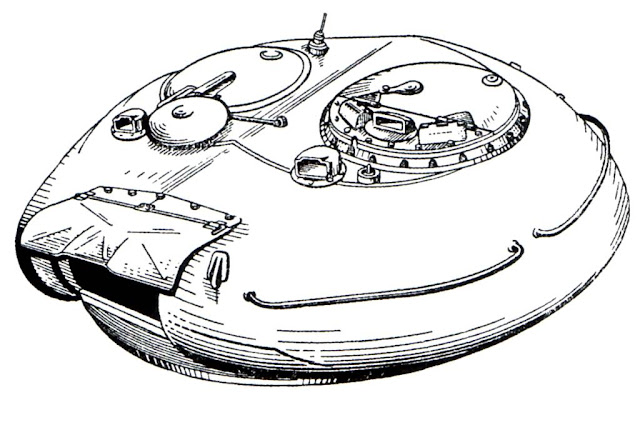
The turret had a very distinct appearance, but in reality, it was merely a reimagination of the hexagonal design of the T-34-85 and T-44 turrets with increased sloping. The turret bustle was shortened which reduced the amount of space available for ammunition, and it gained a wedge shape with a large bevel along its lower half that formed a shot trap. These bevels were included in the turret to ensure that the driver could drive with his head out of his hatch or exit through his hatch regardless of the orientation of the turret.

Like the turrets of the T-44 and T-34-85, this design retained a conventional heavy semicircular mantlet where the gunsight and co-axial machine gun was fitted. The thickness of the gun mantlet can be seen in the cross sectional drawing shown below. At its peak thickness, the gun mantlet reached 200mm. The turret cheeks had a lower thickness but were sloped at a much greater angle due to the curvature of the turret, thus ensuring a higher effective thickness.

The ballistic shaping of this turret was better than the previous versions, but the large shot traps around the turret ring area was considered a huge liability. Other than that, the good angling of the side cheeks of the turret in combination with the well-rounded gunshield provided good protection. The photo below (of an abandoned pillbox turret), provided by Vladimir of Urban3p, shows the curvature of the turret as seen from the gunner's station. The hole at the end is for the TSh-20 telescopic gunsight. By comparing the angle of the wall of the turret to the cannon breech, we can see that the horizontal slope of the turret is quite steep. There is not much in the way of vertical slope, but the turret is rounded. However, the turret ring was protected by rather thin armour in the same way as the T-44 turret, although like the T-44 turret, it had a very low height and was not as exposed as on the T-34-85 turret.
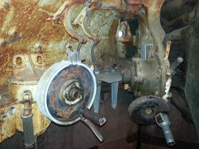
Even though the front of the turret was considerably more resilient than that of earlier medium tank turrets, it was inferior to the front of the hull due to the rather large thickness of the front hull armour and its steep sloping. The shot traps around its front and rear further compromised the integrity of the tank's overall protection scheme.

To solve the issues with the 1946 turret, the design bureau of plant No. 183 created a new turret design in 1948 with an entirely new egg shape that omitted the front bevel. This new turret design not only provided a weight reduction, but also better protection from all directions. However, the rear bevel shot trap remained albeit with significant reinforcement. The height of the bevel was reduced, and the turret gained an armoured collar around its rear sector that not only protected the turret ring from direct hits but also prevented shell ricochets from reaching it.
In 1949, the revised T-54-2, or T-54 obr. 1949, entered production with the new turret. The thickness of the upper glacis armour was reduced to 100mm. The hull side armour was reduced to 80mm. Despite the decreased mass of the frontal hull armour, the level of protection still met the requirements. Having a thickness of 100mm and sloped at 60 degrees, the upper glacis was equal in thickness to the IS-2 obr. 1944 but the crucial difference was that it was made from RHA instead of a high hardness cast steel. As such, the upper glacis of the T-54 obr. 1949 could resist the 8.8cm Pzgr. 39 fired from a Pak 43 or KwK 43 at point blank range whereas the IS-2 obr. 1944 could only resist this round from a distance of more than 450 meters.
According to a Soviet analysis on the amount of armour required to stop an 8.8cm PzGr. 39/43 armour piercing shell fired from an L/71 Kwk 43 or PaK 43 gun, it was determined that an impact velocity of 1,090 m/s was needed to achieve initial penetration on 100mm of RHA sloped at 60 degrees under the V20 criteria (20% chance of complete perforation). Considering that the muzzle velocity of this shell is 1,000 m/s, the probability of achieving initial perforation was 0%. An impact velocity of 1,160 m/s was required to achieve initial penetration on an 120mm of RHA sloped at 60 degrees.

Besides the reduction in the hull armour thickness, another significant change was the shift to a new turret design with a narrow gun embrasure instead of a traditional gun mantlet. The width of the embrasure was just 400mm wide. The base of the gun barrel is protected by a simple gun mask that only offers protection against artillery shell splinters and heavy machine gun fire. The gun mask also prevents fragments or bullets from jamming the gun elevation mechanism by becoming lodged between the gun breech block and the turret.


The gun mask was mounted to an armoured plate affixed to the front end of the gun breech by four large bolts. The gun mask protects the gun breech at all angles of elevation from direct hits and from bullet ricochets or splatter, but when elevated to a high angle, the lower edge of the gun mask clears the base of the turret and and leaves a noticeable gap as the photo on the right above shows (photo by Vladimir Yakubov). This gap can be large enough to allow even small caliber cannon shells to enter, but a heavily sloped internal armoured plate prevents direct damage to the gun breech or the turret ring. When the gun is level, this armoured plate rests behind the base of the turret as the drawing below shows.

One disadvantage to the lack of a gun mantlet was that a tall slit has to be cut into the armour to accommodate the vertical movement of the co-axial machine gun and the aperture of a telescopic gun sight. As long as a telescopic sight is used, there must be a hole in the armour, but as a gun mantlet moves with the elevation of the cannon, a gun sight aperture embedded in the mantlet only needs a single, small hole. The relatively large slit in the turret of the T-54 increases the size of the weakened zone. Examples of tanks that possess this weakness besides the T-54 include the Chieftain tank, which has a tall vertical slit in the front of the turret for the co-axial machine gun, but the Chieftain bypasses the need for a slit for it's gunner's primary sight by using a periscopic sight.
To seal the gun embrasure from the weather, a rubberized fabric seal was provided.


In the year 1951, the T-54 finally gained its iconic rounded turret. The turret has been described in many ways, from "overturned soup bowl" to "hemispherical". In truth, it is a unique shape with complex angles that cannot be summarized easily. From above, it is distinctly egg shaped. From the side, it is more oblong than round. Only from the front does it resemble a perfectly rounded overturned soup bowl. From a frontal perspective, the thickness of the turret is roughly uniform in the vertical axis although the actual physical thickness of the casting varies. However, the horizonal slope of the turret vastly increases the effective thickness of the turret at the edges of the turret silhouette. Roughly speaking, the thickness of the front of the turret ranges from 200mm at an angle of around 0 degrees at the base of the turret to 70mm at an angle of 52 degrees at the top edge of the turret, where the frontal armour transitions to the roof. The sides of the turret are 160mm thick at the base where the angle of the slope is none or negligible, but the side armour thins down to 115mm at the upper edge of the side where the slope is 45 degrees. However, these values are only nominal as the complex shape of the turret makes the actual thickness values difficult to describe. Overall, the high thickness of the armour increases its efficiency against contemporary armour piercing ammunition. For example, WWII Ballistics: Armour and Gunnery notes on page 25 that a 195mm cast armour plate with a hardness of 220-300 BHN at an angle of 0 degrees is equivalent to 195mm of rolled homogeneous armour with a hardness of 240 BHN against projectiles in the 50-152mm diameter range, meaning that it is essentially equal to an RHA plate of the same thickness. The commonly cited efficiency coefficient of 0.85-0.95 for cast armour relative to rolled armour is only true for thinner plates in the 50-100mm range.

Like the previous T-54-2 turret, there is no gun mantlet and the gun is only protected by a cast steel gun mask. The shape of the gun mask is very similar to the type used on the T-54-2, but it is unclear if the same mask design was carried over directly.

However, cutouts were made in the armour at the slits for the co-axial machine gun and the gunner's telescopic sights now. This created weakened zones where the armour thickness is substantially less than the advertised 200mm. The cutout is shown in the drawing on the right and the cutout for the co-axial machine gun can be seen clearly in the photo on the left. The photo on the left comes from flickr user solipsistnation. The combination of reduced thickness and the presence of a hole in the armour makes the co-axial machine gun port and the gunner's sight aperture especially weak to anti-tank fire.


Production turrets were manufactured by chill casting, but there were issues with casting the entire roof along with the rest of the turret in one piece. To fill in the gap, the roof had to be constructed from two D-shaped rolled steel plates, which were welded onto the cast walls in an automated procedure done by a machine rig. This results in a marginally weaker turret compared to a turret made from a single casting as the roof plates might be ripped off at the weld seams or the seams may burst if the roof was struck by glancing cannon fire. However, using rolled steel plates in this location has the benefit of increasing the chance of a ricochet when struck since rolled steel plates invariably have better ballistic properties than cast steel of the same hardness. An illustration of the chill casting mold is shown below.

The welds joining the hull roof to the side hull, and the welds joining the hull roof to the glacis plates and to the floor and all the welds in between were strengthened in the T-54-3 compared to the T-54-2. The geometry of the fittings between the armour plates was changed to increase the surface area between the joints and thus improve the strength of the seams. This helped to improve the armour integrity of the hull and thus improve protection without changing the thickness of the plates. The hull roof is 30mm thick.
The hull and turret were evaluated against anti-tank guns of a myriad of calibers of both domestic and foreign make. The frontal aspect of the tank had to be proofed against common tank guns like the 90mm M3 of the M26 Pershing and the M46, but it was also tested against the tank's own D-10T and the 85mm S-53 of the T-34-85. As the post war reality showed that American 90mm guns would be the main threat to Soviet armour amd not German 88mm guns, the basic requirements for the ability to resist 88mm shells "with a muzzle velocity of 1000 m/s" (referring to PzGr. 39 shell fired from the 88mm KwK 43 L/71) became very convenient as the tank would not have to be uparmoured to deal with the new expected threat. M82 APCBC/HE-T was obtained via lend-lease, and became one of many foreign-made munitions for use in testing.
The photos below show the armour of a T-54-3 pattern model tested against anti-tank weapons of various calibers. Note that the roadwheels are of the spoked type, indicating that the test vehicle is indeed a T-54 obr. 1951, and not a T-54A or T-54B which were fitted with "star" type roadwheels.

The photo above shows scallops in the turret from various shell impacts and the photos below show the setup of the testing rig for comprehensive turret and hull testing.


The sides of the tank turret and hull were tested just as thoroughly as the front, and with weapons of the same variety. Besides large caliber tank shells, the vulnerability of the sides of the tank to large caliber anti-aircraft cannons like the Soviet Army's own 57mm S-60 was also investigated. It is unknown if the widely used Bofors 40mm L/70 was also tested.
Both the upper and lower glacis plates and the side hull plates are constructed from 42SM armour grade steel. The rear armour plate and the roof plate was made from 49S armour grade steel, and the belly of the tank was made from 43PSM armour grade steel. The cast steel turret was made from 74L CrNiMo armour grade steel, while the two-piece roof welded onto the cast turret was made from 43 PSM steel. The 49S and 43PSM steel plates installed in the roof and belly of the tank was quite thin - only 20mm, so it is quite surprising that these steels are rather soft for their thickness. This table states that 49S and 43PSM have a hardness of only 180-250 BHN. The rule of thumb is that thinner plates are easier to harden than thicker plates, so the plates used in the tank are definitely closer to latter than the former, but even so, that is relatively soft for such thin plates. 42SM and 74L, on the other hand, are medium hardness steels that are technically specified to have a hardness ranging from 285-340 BHN. However, it is reported in the study "Повышение Противоснарядной Стойкости Толстолистовой Серийной Стали 42СМ С Помощью Электрошлакового Переплава" (Enhancement of the Ballistic Resilience of Serial 42SM Steel Using Electroslag Remelting), while the technical specifications call for a hardness within the range of 285-340 BHN, serial 42SM steel plates are actually treated to a hardness ranging from 293 BHN to 311 BHN. These steel hardnesses are optimal for resisting armour piercing rounds for the thicknesses of the given plates.
Foreign appraisals of the steel for the armour of the tank were consistently positive. In the (translated) famous Yugo tests document, for example, it was noted that "T-54A cast parts were 270 BHN (rolled plates were 290 BHN) and were judged to be of excellent quality". From this, we know that 74L cast armour steel has a hardness of 270 BHN, while 42SM has a hardness of 290 BHN. The hardness and thickness of the various armour plates were controlled to offer optimal efficiency against the type of armour piercing shells expected to be used by the perceived enemy.

The sides of the turret slope inwards at 60 degrees and converge at the gun mantlet, giving it a rounded needle-nose shape. This shape is excellent for an all-steel turret from a ballistic point of view, but the effect on internal space in the turret is somewhat negative, which is compounded by the fact that the turret of the T-54-3 is also dome-shaped. The sides of the turret that slope inwards to form the needle-nose shape are 150mm to 170mm thick, thickest as it transitions from the turret front and thinner as it curves round to the back. The rear part of the turret sides, at the commander's and loader's areas, are around 100mm to 120mm thick, thickest at the bottom and thinner as the steel curves towards the top.
If we take a close look at the turret wall behind the gunner's primary gunsight, we can see very plainly how the turret immediately assumes a side slope after the gunsight port.

The photo above also shows that the flat part of the front of the turret is shaped like a right angled triangle. This is the weakest part of the T-54 turret, as it is only sloped in the vertical plane. Aside from the flat triangle, the turret is sloped in three dimensions.

As you can see in the photo, the area behind the gunner's MK.4 periscope is distinctly more curved than the rest of the commander's station. In other words, the flat part of the turret is much narrower than it appears in exterior photos.
Penetrating just 147mm at 0 degrees at a thousand meters' distance, M82 was simply inadequate against the T-54. A large portion of the side of the turret has the potential to shrug off a hit from M82 at close range, and the side hull is largely immune at most angles, unless it is struck straight on.
Much later on, the M36 gun became available as well, as nearby Yugoslavia operated 319 M47 Patton tanks. According to the famous Yugoslavian tests, the front of the turret could only be perforated by PzGr. 39-1 APCBC fired from the KwK 43 at a dangerously close distance of 600 meters. The upper glacis was totally immune even from a hundred meters, but the sides of the turret can be defeated at a distance of up to 1750 m.

Fired from the 90mm M3A1, T33 APCBC rounds (shown above) totally fail to defeat the front of the T-54's turret at any range. Shot perpendicularly from the side, the front part of the turret sides can only be defeated at a suicidal range of 250 m. When hot loaded T33 rounds are fired from the higher pressure M36 cannon, the chances improve a bit. The shell is still not capable of getting through the glacis even at a hundred meters, but the front of the turret can now be perforated at 350 m. The frontal part of the side turret can be perforated at 850 m, which is a much more comfortable shooting distance. M304 APDS is mandatory when fighting the T-54, as the front turret can be perforated at 750 m. Nevertheless, the inability to defeat the armour of the T-54 except from the sides can be considered a serious drawback for opposing forces armed with 90mm guns.

M431 HEAT works well at any range on any part of the T-54, but the killing power is low and the shell has fuzing problems on angled parts of the armour. It has a high probability of failing to detonate if it strikes the upper glacis when the tank is angled 20 degrees sideways. The shell may not work properly on the well rounded shape of the turret, especially the top half. Also, M431 was not introduced until the late 50's. Details on the M431 are available here (Link). Fuzing issues with other HEAT rounds were also observed on the T-34-85 during the tests. Of special interest is the performance of the 75mm M20 and the 105mm M27 recoilless rifles. The M310 HEAT round fired from the 75mm M20 fails to defeat the upper glacis armour of the T-34-85 (45mm at 60 degrees) if the side angle was 20 degrees or more and it fails to defeat the upper side hull armour (45mm at 40 degrees) if the side angle was 30 degrees or more. The same result was obtained with the 105mm M27 which could not defeat the upper glacis armour with the M52 round if the side armour was more than 20 degrees. Since the upper glacis of the T-54 is sloped at the same angle as the T-34, the same results can be expected. The sides may be more vulnerable, however, as there are only fuel tanks and stowage bins on the track fenders and no sloped armour plating.
The M82 APCBC/HE-T round packs 200 grams of RDX, but it is largely impotent against the T-54 unless the gunner aimed for the side hull or rear hull and turret. M82 was not included in the Yugo tests, but it is not difficult to predict its performance. According to U.S Army tests detailed here (link), T33 fired from the M3 cannon is capable of defeating the upper glacis (82mm at 55 degrees) of a Panther at a range of up to 1100 yards, but M82 fired from the same cannon cannot repeat the same feat, despite having a capped penetrator. At most, it could deal with the lower glacis - which measured 60mm thick at 55 degrees - at a maximum range of something over 950 yards.
The T-54 offered the next best chance against itself, behind the long-barreled 88mm KwK 43 as the 100mm BR-412B round is capable of perforating the front of the turret at 500 m and the front part of the side turret at 1000 meters. With BR-412D, a better result may be obtained.
The M48 will find itself in a rather bad situation in comparison to the T-54 where hull armour is concerned. It is well known that cast armour is significantly weaker than rolled armour, but the extent is not often grasped by many. In the Yugo tests, testing of domestic M47s have shown that the upper glacis, a 100mm cast steel plate sloped at 60 degrees, can be defeated by BR-412B at a distance of 750 meters even though BR-412B is technically only rated to penetrate 96mm of rolled steel angled at 60 degrees at a point blank distance according to a British evaluation using the same metrics of penetration. The 100mm rolled steel upper glacis of the T-54A is unsurprisingly immune to BR-412B from all ranges. The T-54 can be considered arguably on par with the M48 or the M60 tank in terms of hull armour protection.
There is much more information that can be gleaned from the results of those tests, but only if we pay close attention to detail. The tests involved shooting at the side of the turret from a right angle, but as we know, the turret is sloped inward. If the turret is attacked at a perfectly perpendicular side angle, the front part of the sides of the turret will have a horizontal slope of 30 degrees, thus making the LOS thickness 196mm to 173mm. We know that T33 fired from the M36 cannon is capable of defeating this at 850 m.
However, a shot coming at the turret from a forward 30 degree angle would also have to face between 173mm to 196mm of LOS armour, because the 60 degree inward angle of the turret sides is reduced to just 30 degrees. This means that if the turret is attacked from its forward arc, it may only be as strong as its side in certain parts. In general, the turret becomes more vulnerable as the incident angle increases from 0 degrees to 30 degrees to 50 degrees and so on, up til a point at 90 degrees where it is as vulnerable as it is at 30 degrees. This is a peculiarity of this type of ballistic shaping, and it is not limited to the T-54. The turret of the M60A1 has the same problem, only it is even further amplified because the cheeks of the M60A1's turret are thinner - only 140mm thick. The T-54's turret can be considered to be extremely resilient to anti-tank guns of its time, but it is not without certain weaknesses.
According to British tests, Centurion's MK.3 APDS for the 20 pdr. gun would fail to defeat its own upper glacis (76mm at 57 degrees) at a minimum distance of 4400 yards, or 4023 meters. After the addition of a 44mm weld-on applique armour plate, the distance of immunity was decreased to just 850 yards, or 777 meters. This means that MK. 3 APDS can penetrate less than 120mm RHA angled at 57 degrees at 777 meters, and less than 76mm at 57 degrees at 4023 meters.
According to Swedish archive documents shared by renhanxue, owner and administrator of the Swedish Tank Archives website (tanks.mod16), 20 pdr. APDS (most likely MK. 3) can penetrate 240mm of vertical plate at 500 m, and 95mm at 60 degrees at 1000 yards (914 m), and it fails to penetrate 122mm angled at 60 degrees at 500 m. This is congruous with the aforementioned tests. The hardness of the plate used is unknown. However, the drop in penetration performance is between 4400 yards and 1000 yards is suspiciously small for an APDS round. It is possible that the Centurion's rolled steel plates are softer than the test plates used during the Swedish tests.
Taken all together, this means that using MK. 3 APDS, a Centurion Mk. 3 should have the ability to defeat the upper glacis plate of a T-54 only from below 900 meters. This makes the Centurion the best performer among all of its Western peers in a hypothetical face-off against Soviet T-54s.
Let's see how MK. 3 does against shallowly sloped plates:

So, MK. 3 can confidently defeat 150mm RHA angled at 30 degrees at about 1750 yards, and pierce 120mm RHA angled at 25 degrees at up to 2250 yards. This would allow it to perforate the base of the T-54 obr. 1951 turret in the region around the gun mantlet, but the frontal arc of the turret is still capable of resisting a hit from MK. 3.
According to Swedish test data provided by renhanxue, 105mm L28 penetrates 200mm RHA at 30 degrees at 1500 m, and 140mm RHA at 55 degrees at 900 m. On the Tank-Net forum, renhanxue states that the British give a penetration value of 120mm RHA at 60 degrees at 1000 yards for L28. Overall, this means that the turret of the T-54 is vulnerable from combat ranges of 1500 meters and beyond, so the 105mm L7 gun is an effective countermeasure against the T-54 in a frontal attack.
Additionally, any evaluation of the T-54's survivability is not complete without also reviewing the value of its relatively small silhouette. Being quite small for a tank, the T-54 is easy to conceal in vegetated areas. The small surface area of the tank also makes it less time consuming to camouflage.

Although it is an aspect of the T-54 design that is often criticized, a small silhouette was not only coveted by Soviet tank designers. It was a common goal of practically every major military power that was influenced by statistical probabilities calculated from years' worth of combat data. For example, the height of the M60A1 was recognized as excessive and the M60A2 introduced a low-profile turret design to minimize the projected area of the turret while maximizing protection.


The add-on armour featured on the T-55AM and its variants is referred to as metal-polymer armour blocks. This type of armour has already been covered in Tankograd's T-62 article. It would be pointless to repeat it all here, so please head over to the T-62 article to read more. However, the unique geometry of the turret of the T-54 means that the spacing between the turret and the add-on armour blocks is not the same as on the T-62, which is a nuance worth examining.

As mentioned earlier, the turret of the T-54 had a variable thickness and had a very complex range of sloping angles due to its rounded shape to ensure that the entire height of the turret had an equal thickness of steel. This was designed so that the turret could attain a uniformly high level of protection against steel full caliber shells and APCR rounds with tungsten carbide cores. The shape of the metal-polymer armour blocks on the T-55M and T-55AM turrets was therefore designed accordingly.
According to Soviet drawings, the total thickness of turret armour including the "Brow" armour blocks amounts to 500mm when measured at the center of the block. At the top of the armour block, the thickness of the cast steel front plate decreases but the metal-polymer composite armour increases and the air gap behind it also increases to compensate. At the bottom of the armour block, the cast steel front plate of the "Brow" armour block is thickest but the metal-polymer composite has its smallest thickness, as does the air gap. Due to the complexly differentiated thickness of the armour elements, the total LOS thickness of the turret differs at the locations where the "Brow" armour block is present.

The variable thickness of the cast steel front plate can be seen clearly in the photo below, taken from Andrei Tarasenko and originally uploaded to his blog. The subject of the photo is a Czechoslovak T-55AM2, but the armour is identical to the Soviet T-55M and T-55AM.

At the top half of the armour block, the cast steel front plate has a thickness of 71mm, the armour is sloped at an obliquity of 30 degrees and the total thickness of the armour is 280mm. At the bottom half, the cast steel front plate has a thickness of 85mm and the entire armour block is sloped at an obliquity of 15 degrees.


The size of the air gap is known thanks to measurements provided by Georg Stark and published in Paul Lakowski's "Modern Armour". It is now known that "Modern Armour" uses very old estimates and figures, but some of the information, like the photo and sketch below, is accurate as it was measured directly on the tank in question.

As the sketch shows, the air gap between the metal-polymer composite block and the turret ranges from 50-60mm at the bottom to around 200mm at the top, directly corresponding to the thickness of the metal-polymer composite block itself. At the top of the armour block where the air gap is 200mm, the turret armour has a thickness of 100-110mm and is sloped at 54 degrees for a LOS thickness of 178mm and the "Brow" armour block itself has a LOS thickness of 323mm. By adding up the cumulative thicknesses of the "Brow" armour block, the air gap and the turret armour, it is calculated that the armour array has a total thickness of 659mm at this location. Using these methods, it is determined that the at the bottom and middle of the turret, the LOS thickness ranges from 480mm to 500mm but it reaches up to 660mm at the top. The turret armour itself remains at a uniform thickness of 170-180mm at these zones.
The presence of an air gap behind the armour array gives room for KE projectiles to break apart as the buildup of internal stresses from the penetration of the steel front plate and the moving internal plates is suddenly released, thus magnifying the effect of the armour. For shaped charge jets, the air gap gives room for disturbed jet particles to disperse such that they do not contribute to the total penetration depth from the residual jet tip.
The belly armour was enhanced with rudimentary spaced armour plate welded onto the hull. Six 20mm steel plates were welded onto the front half of the tank belly with the proper spacing of 80mm ensured by a steel frame. Unlike more modern mine and IED protection kits, there is no low-density filler between the spaced plate and the tank belly so there is little blast attenuation aside from the spaced 20mm plate. The main function of the spaced armour would be to prevent the tank belly from being breached by an explosion.
The drawing on the left below shows the tank's escape hatch with its spaced plate armour and the drawing on the right below sows the spaced belly armour kit from a profile view.


The separate spaced plate sections can be seen below. There are ports built into the armour for drainage plugs.

As the T-54 was formulated during the closing years of WWII and was only finalized a few years after its conclusion, no considerations were made for the effects of nuclear destruction. As part of tests carried out between 1952 and 1953 to determine the effects of nuclear weapons on various ground equipment, including tanks, the T-54 tank was exposed to a nuclear explosion from various distances. As it turned out, even at large distances, the turret could be displaced by the sheer power of the nuclear winds even when the turret was locked in the travelling position, causing the gear teeth around the turret ring to break and render the tank unserviceable. As a result of these tests, the turret locking mechanism was strengthened, so that even at around 300 meters' distance from the detonation of a 2 to 15 kiloton bomb, the tank remained serviceable.
However, it was discovered in subsequent tests that at distances of up to 700 meters, animals (rabbits, dogs) standing in for the tank crew died immediately from the shock wave and overpressure of the blast. As a result of these findings, the requirements for a comprehensive anti-nuclear protection suite for the T-54 were drawn up, and in 1956, the KB-60 design bureau from Kharkov finalized a "PAZ" (Nuclear Protection System) complex and sent the technical documentation to the Uralvagonzavod tank factory for implementation.
The T-55 was the first Soviet medium tank to feature an NBC protection system. It was an advanced collective type system with automatic and semi-automatic operating modes. A gamma radiation sensor was used to detect the detonation of a nuclear bomb and initiate countermeasures before the shockwave could reach the tank. The system could react 0.3 seconds after detecting a spike in gamma radiation. All openings in the tank would be automatically sealed by heavy steel wedges activated by explosive squibs. The engine and the cooling fan would be stopped, and the armoured louvers over the engine deck would be closed, all done automatically.

The ventilator intake fan on the turret roof lacked a filtration unit and was insufficiently powerful to create an overpressure inside the tank, and there was no additional space to add these necessary features. As a result, it was replaced by a new ventilator intake system that included a supercharged blower. The supercharger drum is placed right beside the co-axial machine gun, in front of the loader. Not only was it capable of producing an overpressure inside the tank to prevent foreign particles from seeping in, the filtration system could also remove chemical and biological agents, though only when activated, either manually or automatically. In normal operation, the powerful compressor fans are not used, and the ventilation system performs the same basic function as the old dome ventilator.
The T-55A obr. 1967 provided an additional layer of security from the harmful effects of a nuclear explosion by including a special anti-radiation lining. The anti-radiation material is a lead-impregnated polymer composite textile that is layered and cut into the desired form before it is installed on the surfaces of the tank. It is designed for absorbing gamma radiation - the most dangerous form of radiation as it can penetrate even relatively large thicknesses of steel - but it can also perform a secondary function as a spall liner when present in sufficient thickness.
The anti-radiation lining is secured onto the internal surfaces of the fighting compartment by bolts. They mainly cover the areas of the tank where the armour thickness is lower and therefore less effective at attenuating gamma radiation and neutrons. The turret ceiling is completely covered by the lining and most of the turret rear and sides are covered. Even the hatches have a layer of anti-radiation lining.


The commander's cupola and loader's cupola on the T-55A both had relatively high radiation permeability due to their relatively low thickness of armour. As such, a large thickness of anti-radiation lining was needed to ensure a sufficient level of protection, but this thickness was too large to be practical as a lining on the internal surfaces of the cupolas. Instead, the anti-radiation material was installed outside the cupolas in the form of prefabricated conformal blocks and given a sheet steel shell to protect it from the weather and from the initial blast and heat of a nuclear explosion. Anti-radiation material was also added to a small strip of the turret roof joining the two cupolas.

The large thickness of the anti-radiation blocks on the loader's cupola can be seen in the two photos below. If this amount of material was used as an internal lining instead, it probably be so thick that it may constrict the size of the loader's hatch and it would certainly severely restrict his headroom.


The commander's cupola received similar treatment. However, the commander's hatch and cupola roof has a noticeably larger thickness of external anti-radiation cladding compared to the loader's hatch, and this is because a lining would have intruded much more into the commander's available headroom than for the loader, who is not confined to a fixed position underneath his cupola.

The driver's hatch also received an anti-radiation cladding.
The T-54 has an escape hatch. It is located behind the driver's seat. It is held in place by four locks. Once all four have been disengaged, the hatch drops down, allowing the crew to crawl out. It is much easier said than done, and it will be nearly impossible to do a quick escape from a hatch of such small size, but having a hatch presents unique tactical opportunities as the crew can exit the tank without being seen by the enemy.


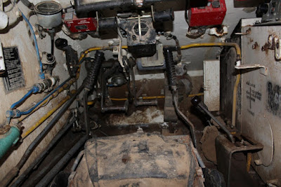
The driver's station in the T-54 was a departure from the T-34 driver's station in that it had less headroom due to the significantly shortened hull, but the driver's comfort and visibility improved because the periscopes were relocated from a hatch on the upper glacis plate to the hull roof. This meant that the driver could be seated in a far more natural posture while driving. There were also other ergonomic improvements were added for the driver's benefit, such as handlebars built into the periscopes for the driver to hold on to as he ingresses or egresses from his station. The driver's station changed very little throughout the evolution of the tank, as exemplified by the two photos above. The photo on the left shows a T-54A and the photo on the right shows a T-55. The only major difference is the absence of a bow machine gun on the latter tank.
We have already examined most of the components of the driver's station in Tankograd's T-62 article. As the driver's station in a T-62 is almost identical to one from a T-55, there is no point to repeat it here. Please head over to the T-62 article. However, there are some small historical details that uniquely belong to the T-54.
The design of the driver's hatch of the T-54 was finalized on the T-54 obr. 1947 and it was retained throughout the production life of the tank series. The design is shown in the drawings below. The thickness of the hatch was equal to the hull roof: 30mm. As mentioned before in the article when examining the ventilation system of the T-54, the driver's hatch had a small ventilation porthole designed to work in conjunction with the ventilation exhaust fan at the back of the fighting compartment, in the engine compartment bulkhead. Besides that, there was a layer of padding on the underside of the center of the hatch to protect the driver's head from a hard knock, and the rim of the hatch opening was lined with rubber on both sides to seal the hatch from the weather and to provide some protection for the driver's head. These details can be seen in the drawings below.
One side of the hatch opening is slanted which was necessitated by the overhang of the turret over the turret ring. The dimensions of the hatch opening are not particularly large but it is reasonable. It is particularly important to note that the width of the hatch is 486mm which is substantially more than the average shoulder width of an average Soviet Army conscript, so in general, the size of the hatch can be considered sufficient for a tank driver even when wearing winter clothing.


The driver's sat in a bucket type seat. It had bolsters on the sides and a well-padded cushion and backrest. It could be adjusted in height, with the tallest setting meant for driving with the driver's head outside the hatch. The backrest could be adjusted between just two angles of recline, which is rather unfortunate. However, the backrest can be easily folded fully backward or forward in order to allow the driver to freely move into the fighting compartment or evacuate the tank via the escape hatch behind him.

The periscopes of the T-54 also deserve some mention. Originally, destroyed periscopes were almost impossible to remove if a powerful shell struck the armour in front of it as the mounting piece would usually be damaged in a most inconvenient way. This was solved in 1953 by using a heat-treated mounting piece of a higher grade of steel, increasing the strength of the welds and by thickening certain components.
In 1951, the TVN-1 infrared night vision driving periscope was introduced along with an infrared headlight on the T-54 obr. 1951. With the help of the tank commander who was provided with the new TKN-1 night vision monocular periscope, the driver of the T-54 gained the ability to navigate at night more stealthily than if conventional white light headlights were used and tank units could march more confidently at night. When the more capable TVN-2 night vision periscope became available in the late 1950's, the TVN-1 was phased out in favour of the newer type. The two images below show TVN-2 periscopes installed in the appropriate periscope slot.


For a more detailed examination of the night vision devices, please head over to Tankograd's T-62 article.
The mobility characteristics of the T-34-85 were largely retained, but it is somewhat worse than the T-44 due to the large difference in weight. The T-34-85 had a combat weight of 32 tons and with a gross engine output of 500 hp, the tank ostensibly has a power-to-weight ratio of 15.6 hp/ton. The T-44 had a combat weight of 31 tons and an uprated V-44 engine with an output of 520 hp, so it had an increased power-to-weight ratio of 16.8 hp/ton. However, the net power available at the drive sprockets of the T-34-85 is 390 hp after all the power deductions from the cooling system, generator, and other auxiliary equipment are made. The actual power to weight ratio is 12.2 hp/ton.
Having a gross output of 520 hp, the V-54 engine gave the T-54 obr. 1949 a nominal power-to-weight ratio of 14.65 hp/ton, but the net power is 430 hp so the real power-to-weight ratio is actually 12.2 hp/ton. When the gross powers are compared, the power-to-weight ratio of the T-54 obr. 1949 is 6.3% lower than the T-34-85, but when the net powers are compared, the two tanks are equivalent.
The engine was installed transversely in the hull and was connected to the transmission by a transfer case that contained the main clutch.

One of the immediate benefits of the transverse engine position is the increased power transmission efficiency gained by omitting a bevel gear to transmit the driveshaft power to two axles, which is necessary when the engine is installed longitudinally. Alone, a bevel gear incurs a power transmission loss of 4%, as the drawing below shows. The drawing was taken from page 432 of the Soviet tank design handbook "Tank" (1954).

The transmission was quite compact and its external appearance was similar to the transmission of the T-34. Above it were the water and oil radiator packs and the accompanying radiator fan. This layout made it possible to greatly decrease the volume of the engine compartment by decreasing its length, and most importantly, this design solution did not have any caveats.
The T-34-85 had a top speed of 55 km/h, while the T-44 had a top speed of 51.1 km/h. The first mass-produced model, the T-54 obr. 1947 had a restrictive top speed of just 43.5 kph. The V-54 was slightly underpowered for the T-54 obr. 1947, so the top speed had to be compromised by adjusting the gearing ratios in the gearbox to preserve the acceleration characteristics of the tank. The T-54 obr. 1949 and the definitive T-54 model, the T-54 obr. 1951, finally settled on a slightly more modest weight which permitted a top speed of 50 km/h to be achieved.
Fuel is delivered by a direct injection system. The engine has a 14-15:1 compression ratio.
Not all of the engine's power is used to propel the tank as some power must be transferred to the centrifugal radiator fan for the tank's cooling system, the air cleaning system, and the G-73 electric generator for the tank's electrical systems. The net power available to propel the tank is 430 hp. This constitutes 82-83% of the gross power.

The V-55 is a modification of the V-54 engine with an increased output. It generates a maximum power output of 580 hp at an engine speed of 2,000 rpm and a maximum torque of 2,254 N.m at an engine speed of 1,200-1,400 rpm.
Thanks to the increased power of the V-55, the gross power-to-weight ratio of the T-55 increased to 16.1 hp/ton.
The added power comes from a better optimized compression ratio of 15:1 ±0.5 and an improved fuel injection system. The V-55 was paired with a new and improved VTI-4 air filter which helped by reducing the power loss in extremely dusty environments.
Aside from the increased automotive performance, the new engine was more robust and reliable. It was delivered to the Soviet Army with a warranty of 350 cumulative hours of engine operation.
Due to the power allocated to the G-5 electric generator for the tank's electrical systems and the addition of an AK-150 air compressor, the net power available to propel the tank is only 480 hp. This constitutes 82.76% of the gross power.
In the Soviet tank design handbook "Tank" (1954), it is stated on page 432 that the energy loss from friction from a mechanical (manual) gearbox is 6%. From there, the power is transmitted to the final drives, where an additional power loss of 1% is incurred. With this high level of efficiency, most of the net engine power is transmitted to the drive sprockets with only a small amount becoming heat. In turn, this indirectly increases the power available to propel the tank as it reduces the amount of power that must be allocated to the cooling system.
The superior gearbox and steering system of the T-54 enabled the tank to get more out of its 520 hp engine by allowing the driver to shift gears much more quickly and also to steer more precisely and with much less effort. Moreover, the new super-compact dry plate clutch transmission enabled the T-54 to retain the agility of the T-34-85 despite having a worse power-to-weight ratio, especially at higher speeds. This is because the T-34-85 was steered via the clutch-and-brake system which robbed the tank of some of its speed with each turn. The top speed and acceleration of the T-54 when travelling in a straight line was worse compared to its predecessor, but when travelling on actual roads or when moving cross-country, the T-54 was comparable.
According to the official figures presented in manuals, the average speed of the T-34-85 reaches 30 km/h on paved roads and reaches 25 km/h on dirt roads whereas the T-54 obr. 1951 reaches an average speed of 30-33 km/h on paved roads and 20-25 km/h on dirt roads. It is reasonable to assume that these figures were derived from a standardized test where both tanks ran the same course at Kubinka under the same conditions albeit at different points in time, so in all likelihood, these average speed figures should be directly comparable. With that, it can be seen that even though the T-54 cannot reach a top speed as high as the T-34-85, it did not suffer in terms of mobility in realistic conditions where the tank must be navigated through a course that involves maneuvering rather than simply driving in a straight line. The uprated engine of the T-55 tank allowed it to achieve an average speed of 32-35 km/h on paved roads and 22-27 km/h on dirt roads, thus surpassing the T-34-85 by a small margin.
(This section was written by the user "AKMS", administrator of the Milimoto blog. The original article from which this section was derived can be found here)

The T-54 used a 5-speed manual transmission with a syncromesh gearbox. In the T-54 gearbox, the speeds ranging from the 2nd to 5th are controlled using the synchromesh system, but the 1st gear and the reverse gear still used the less advanced constant mesh system. The lack of a synchromesh system on the 1st gear was typical of old synchromesh gearboxes and it was not a real disadvantage for the T-54 because the driver only engages the 1st gear while the tank is motionless, and when the vehicle is motionless, a synchromesh system is not necessary. It was the same for the reverse gear, and in fact, modern vehicles with manual gearbox typically don't use a synchromesh system in reverse.
The use of a synchromesh means that driver does not have to use double declutching for gear changes. As there was no need for double declutching, the time required for gear changing is reduced and the amount of driver experience required to drive the tank was also reduced. Because of these advantages, practically every modern passenger car with a manual transmission use a synchromesh system. For comparison, T-34 tanks produced since 1943 used a 5-speed unsynchronized gearbox with a constant mesh system. That means that the T-54 gearbox had a serious advantage over the gearboxes of late production T-34 tanks such as the T-34-85.
Additionally, in the Polish book "Teoria ruchu pojazdu gąsienicowego" (Theory of tracked vehicle movement) written by Zbigniew Brudziński, it is stated that for a synchromesh gearbox, a gear change typically requires 1.0 to 1.5 seconds. For comparison, a gear change in a unsynchronized constant mesh transmission typically requires 1.5 to 2 seconds. Moreover, Brudziński writes that in an unsynchronized sliding mesh transmission such as the 4-speed gearbox used in early T-34 tanks (up until 1942), a gear change requires 2 to 3 seconds.

The drawing below shows a top view of the transmission with its kinematic components and connections. The T-54 transmission has 3 parallel shafts located longitudinally relative to transmission body. Due to the transverse mounting of the gearbox, the shafts are located transversely relative to the tank hull. The First shaft works as the power input. It receives power from the engine through an intermediate power transfer mechanism and main clutch (which are located between engine and gearbox). The first shaft transmits power to the second shaft, and the second shaft acts as an intermediate to transfer power to the third shaft, which is the main shaft.

The gears on the second and third shafts are paired together. The specific pair of gears used for power transmission from the second shaft to third shaft depends on the gear shift lever position. The synchronizers used for engaging gears are located on the third shaft. The third shaft transfers power to the steering mechanism.
The main clutch is a multi-disc dry clutch. It is is located between engine and gearbox, or more precisely, it is between the gearbox and intermediate power transfer mechanism. The main clutch is used for declutching the gearbox from the engine, like in a typical passenger car with manual gearbox. For declutching, the driver uses the clutch pedal.
T-54 uses a double-stage epicyclic steering mechanism. Each track has a separate steering mechanism with separate epicyclic steering units. The left steering tiller operates the left epicyclic unit, and the right tiller operates the right epicyclic unit. The two systems are completely isolated, so pulling on one steering tiller has no effect on the other. In both epicyclic units the ring gear works as the power input - power from the engine is delivered to the ring gear via the driveshaft from the gearbox and it transfers power into the rest of the gears. The planet carrier works as the output - it gets power from the ring gear (through the planets) and transfers power to the final drive, which transfers the power to the track via the drive sprocket.
In the T-54, the steering tillers have 3 main positions. The 1st position allows the track to move at its full forward speed, the 2nd position generates a reduced track speed by engaging a reduction gear, and the 3rd position is used for track de-clutching and braking. When driving the tank, if the driver changes the right tiller position from 1st to 2nd without changing the left tiller position (still in the 1st position), the speed of right track is decreased but left track still moves at its full forward speed. This causes the tank to turn to the right.
If the tiller is in the 1st position, the clutch of the steering mechanism keeps the sun gear and planet carrier connected, so that one rotation of the ring gear produce one rotation of the sun gear and one rotation of the planet carrier. If the tiller is in the 2nd position, the ring gear is disconnected from the sun gear, and the sun gear is braked by a small internal brake. Thus, the planets rotate around the sun gear and one rotation of the ring gear is faster than one rotation of the planet carrier in a ratio of 1.42. Changing tiller position from the 1st position to the 2nd position decreases the planet carrier speed, but increase the torque on the planet carrier. As a result, the speed of the drive sprocket is reduced but its torque is increased. If the driver puts the steering tiller on the 3rd position, the sun gear is disconnected from the planet carrier but the sun gear is not braked. Instead, the planet carrier is braked by the main brake. In this tiller position the track is braked and de-cluched, so it is disconnected from the drivetrain.
Regardless of the turning direction, the faster track moves at its full forward speed while the slower track has a lower speed than during a forward ride, and the hull moves at a lower speed than during a forward ride as it turns. In Polish terminology, this idea is categorized as a "second group steering mechanism". Steering mechanims which are included into the second group may be based on side clutches or on epicyclic gearing. Second group steering mechanisms include systems that do not feature regenerative steering (side clutches) and systems which feature regenerative steering (epicyclic gearing).
When the driver changes the steering tiller from the 1st position to the 2nd position, the track speed is decreased but the torque delivered to the track is increased. As such, the T-54 steering mechanism can be used as a reduction drive that may be used when additional torque is needed. For example, if the driver sees a steep hill, he can pull both tillers from the 1st position into the 2nd position to increase the torque delivered to the tracks to propel the tank until it reaches the top, whereby the driver returns the tillers to the 1st position. This method of torque boosting cannot be used for prolonged periods. According to the Polish army "Podręcznik czołgisty" (Tanker handbook), the driving distance should not be greater than 100-150 meters when using this method. This is enough for climbing hills, extricating another tank from a ditch by towing, knocking over obstacles, or performing some other operation that requires higher torque.
There are two main turning radii. If the driver wants to gently turn the tank, the first turning radius of 9 meters is used. With both tillers starting in the 1st position for normal forward motion, the driver pulls one tiller to the 2nd position while keeping the other on the 1st position. In this case both tracks move forward relative to the hull but with different speeds. When the first turning radius is being used, the T-54 steering mechanism operates with regenerative steering. Regenerative steering means that during a turn, power is transferred from the slower track into the faster track. That means that the faster track not only receives power from the engine, but also from the slower track. As such, a tank with regenerative steering requires a lower engine power to turn compared to a tank that does not feature regenerative steering idea. The turning radius of the tank does not depend on the selected gear. The drawing and citation below, taken from the Polish book "Teoria ruchu pojazdu gąsienicowego", details the regenerative steering concept in the T-54 steering mechanism:

From the book, translated by AKMS of the milimoto blog:
"Power which is transferred from the epicyclic gear of the slower track into main shaft of mechanism, circulates inside closed circuit: axle of faster track sprocket wheel - final drive - vehicle hull - final drive of slower side - epicyclic gear of this side of vehicle - main shaft of mechanism - epicyclic gear of faster side - final drive - axle of sprocket wheel of faster vehicle side. Power transferred from slower track into faster track is called "regenerative steering". This is the recuperation power, which must be additionally generated by the engine if power were not transferred from the slower track into the faster track"
In other words, in T-54, when the first turning radius is being used, power is transmitted from the engine into the faster track through the gearbox, the faster track moves the hull, hull movement propels the slower track (hull movement powering slower track), and power is transferred from the slower track into the faster track. This situation is visible on the drawing above.
The transmission permits the tank to execute pivot turns but not neutral turns. A pivot turn is where one track is driven forward or rearward while the other track is stopped with the tank turning around the stopped track, and a neutral turn is where both tracks are driven in opposite directions with the tank turning around the reversing track. When performing a pivot turn, the tank is using its second turning radius. To execute a pivot turn in a T-54, the driver must have one tiller on the 1st or 2nd position while pulling the other tiller to the 3rd position. The tiller placed in the 3rd position causes the corresponding track to be declutched and braked, thus immobilizing it. The tank rotates around the immobilized track, effectively steering the system via the traditional clutch and brake method. In this case there is no regenerative steering. If the propelling track is driven with the steering tiller in the 1st position, the tank performs the pivot turn at its maximum speed for a given gear. When the 2nd position is used, the torque delivered to the propelling track is increased while its speed is decreased and as such, the tank turns more slowly but more firmly.
Other than a "second group steering mechanism" like in the T-54, Polish terminology also includes the "first group steering mechanism" category. First group steering systems are based on a differential or multiple differentials. In a first group steering mechanism, pulling a tiller decreases the speed of the corresponding track while automatically increasing the speed of the opposite track compared to its normal forward speed. That means that during a turn, the hull moves at a speed equal to its full forward speed. Inside first group of steering systems, there are systems which don't use regenerative steering (braking differential) and systems which use regenerative steering (controlled differential).
Generally, steering mechanisms belonging to the second group produce a lower hull speed than first group steering mechanisms during a turn, but on the other hand, the load on the engine during a turn is lower when a second group steering mechanism is used compared to a first group steering mechanism. However, it should be emphasized that this is a generalization and there may be exceptions.
In the T-54 steering mechanism, the main brake is used not only for pivot turns (one tiller in the 1st or 2nd position, another tiller in the 3rd position), but also for vehicle braking during forward motion. The driver can use the steering tillers for braking during forward motion by pulling both tillers to the 3rd position. Of course, if the driver puts both tiller into the 3rd position, the tracks are not only braked but also are disconnected from drivetrain. If driver wants to brake the tank without de-clutching the tracks, he can step on the brake pedal instead. In some Soviet tanks with similar steering mechanism, a brake pedal is not provided. For example, Soviet heavy tanks like the IS-2, IS-3 and T-10 lack a brake pedal. The drivers of these tanks must pull both tillers to the 3rd position to brake, and the side effect of this is that the driver cannot brake the tank without de-clutching both tracks.
Driving a T-54 is less fatiguing than driving a T-34. Thanks to a hydraulic assist mechanism, the pulling force on the steering tillers is 12 kilogram-force (kgf), compared to around 30 kgf in a typical T-34 (27-36 kgf for a T-34-85). Additionally, in T-54, the clutch pedal is also hydraulically assisted and it also requires 12 kgf to depress. In a T-34, the maximum acceptable force on the clutch pedal is 25 kgf. The data for the T-54 comes from the Polish "Tanker Handbook", and the data for the T-34 comes from a Soviet test and Polish manual from 1961 (T-34-85M manual).
The transmission casing is made from cast aluminium. It is air-cooled by the centrifugal cooling fan. The power takeoff unit that transfers power from the engine to the tank's auxiliary systems is on top of the transmission casing. The power takeoff unit connects directly to the first shaft of the gearbox which receives power from the engine, and there is no intermediate gearing so the amount of power supplied to the power takeoff unit changes only when the output of the engine itself changes. The block splits the power between three smaller drive shafts. One goes to the AK-150 air compressor (if installed), another is connects to the centrifugal cooling fan, and the third connects to the radiator coolant pump.


The three L-shaped protrusions on the top of the transmission casing are part of the gear shifting system. They are connected to the gear shift lever. The three loops on the corners of the transmission casing are lifting eyes, to be used with a winch to lift the entire unit out of the tank's engine compartment such as shown in the photo below.


Like many tanks preceding it, the T-54 has the option of using compressed air to start its engine. There are two 5-liter air canisters mounted in the driver's station that are used to inject air into the cylinders of the engine, forcing the pistons into motion. This method is harsh on the engine, but dependable. Starting the engine in the summer is usually done electrically, but in the wintertime, the electric starting system may not be reliable due to piston lockup, so using air is necessary. In the harshest weather conditions, with the most poorly maintained T-54, starting the engine will require a combination of both methods simultaneously.
However, like the T-34, the compressed air tanks in a T-54 are not refilled automatically, so the reserves of compressed air is limited. This was changed in the T-55, which was equipped with an AK-150 V-shaped air compressor. The AK-150 is a typical two-stage reciprocating compressor, and like any other compressor of its type, the second stage piston is shorter than the first, and the two are linked by a cooling tube for the forced air cooling system used to regulate the heating of the piston cylinders during normal operation. The compressor is powered via an input shaft from the engine that is independent of the gearbox, thus allowing it to continue running even if the tank's gearbox is set to neutral. When it is in normal operation, the compressor uses 1.1 to 2.2 kilowatts of power (1.47-2.95 hp) depending on the engine speed. As such, the compressor would reduce the net power delivered through the transmission by an average of 2 hp when it is running.
The AK-150 compressor can be seen in the photo of the exposed engine compartment above, partially obscured, and the pneumatic starter system of the T-55 is illustrated in the drawing below.


It must also be said that the T-54 is extraordinarily light compared to its foreign counterparts. Weighing in at only metric 36 tons dry, it is lighter than a generic Centurion tank (52 metric tons) by an entire 16 tons, and lighter than an M48 tank (45 metric tons) by 9 tons, and despite this, it is comparable in most respects and manages to achieve superiority in others. The light weight of the tank enables it to not only exploit bridges intended for light loads, but to also use pontoon bridges and scissor bridges with impunity, as there will be a large load surplus. A large convoy of T-54 tanks may cross a pontoon bridge without needing to take turns.

The T-54 exerted a ground pressure of 0.8 kg/sq.cm, whereas the newer and heavier T-55 exerted a ground pressure of 0.81 kg/sq.cm.

Like the T-44 before it, the T-54 used torsion bars instead of the famous Christie spring suspension of the T-34. The tracks were unsupported and ran directly on top of five large diameter rubber-rimmed roadwheels. The drawing above shows the suspension of a typical T-54 with the shock absorbers behind the first, second and last roadwheels on either side of the hull clearly visible.


Due to the lack of space above each roadwheel swing arm owing to the lack of support for the returning track, it was not feasible to install a conventional linearly actuated hydraulic shock absorber, so a compact vane-type rotary hydraulic shock absorber was installed. The shock absorber arm is joined to the roadwheel arm by a rod.

The rotary shock absorber contains four chambers separated by two vanes with constricted openings for hydraulic fluid to pass through. Vertical motion of the roadwheel swing arm deflects the lever arm of the shock absorber, transforming linear force into torque which is applied to the vane rotor. The rotary motion of the vanes displaces the hydraulic fluid from the high-pressure chamber to the opposing low-pressure chamber via the vane opening. The restriction of fluid flow through a small opening creates a resistance to motion, converting kinetic energy into thermal energy, thus damping the force applied by the roadwheel.

The torsion bars were swapped out for better ones made by electroslag remelted (ESR) steel in the T-55AM modernization and the variants thereof. One reason for this upgrade was simply the desire the improve the mobility of the tank to a more modern standard and improving the quality of the ride, but another reason was the added weight of the tank from the add-on "Brow" armour. The superior steel of the new torsion bars combined with the heavier mass of the modernized tank improved the damping of vibrations.

As with earlier Soviet medium tank tracks, the T-54 uses OMSh tracks. OMSh stands for open metal-pinned tracks. The single-pin track links are held together with bare metal pins which are only secured on the inner end of the track by an oversized head. There are no clips or fasteners to retain the pin on the other end of the track, so when the tracks move, the pins gradually come loose and eventually worm their way out of their slots, but only in the direction of the hull. A steel ramp is welded onto the side of the hull just next to the drive sprocket to knock these loose pins back into the track.

The T-54 obr. 1947 used a proprietary OMSh track design with a width of 580mm that was not carried over to later T-54 models. Beginning with the T-54 obr. 1949, a new OMSh track design was implemented and this came to be the standard design for the T-54 family and its derivatives for the next two decades. These OMSh tracks can be easily identified by the distinctive loop at the end of each track link. The track links are made from cast steel. There are 90 links on each side. The track width remained the same at 580mm and the track pitch is 137mm.


The requirement for the lifespan of the track was fulfilled by the original OMSh track design of the T-54 prototypes, four years before the new OMSh track for the T-54 obr. 1949 was developed. Recall that the T-54 was developed under a set of six requirements, the fifth being: "Develop a robust track and track pin (increase track life to 3,000 km)". Testing in 1946 revealed that the T-54 prototype drove 20,000 kilometers and wore out 6 pairs of tracks, equating to an average lifespan of 3,333 kilometers per track, thus exceeding the original requirements by an average of 11.1%.

There were no rubber bushings and no rubber pads on the inner surface of the track links. Furthermore, the open design of the tracks meant that sand and dust could slowly accumulate inside the gap between the track pin and the track link socket. The abrasion from these foreign objects could wear out the track pins which could make them more susceptible to breaking, thus increasing the probability of the tank throwing a track when performing a hard maneuver of some kind. The deficiencies of open-type tracks were recognized and work was done to implement new track designs with an increased lifespan.

To improve the lifespan of the tracks, a new RMSh track design was developed by the Omsk Transport Engineering Plant with development concluding in 1962. Beginning in 1966, these new RMSh tracks were fitted to new-production T-55 tanks on a mass scale and the new tracks gradually replaced old OMSh tracks on existing T-54 and T-55 tanks as they wore out during normal use. However, the new track did not become a common sight until much later because large stockpiles of OMSh tracks had been accumulated in the Soviet Army and there was a plentiful supply of spares.
RMSh stands for rubber-lined metal tracks. The tracks have the same width of 580mm as the previous OMSh track design. The track pitch is 137mm, which is also exactly the same as the previous OMSh track design. The track pins are hexagonal and fit into the rubber-lined track pin sockets in the track links and are fastened at the ends with hexagonal nuts.

These tracks were not only designed for increased durability but also higher dynamic loads, so they were built heavier and sturdier than the OMSh design. A full set of ninety seven RMSh track links weighs 1,655 kg. Theoretically, the increased mass of the tracks increased the rolling resistance of the tank which translates to a reduction in the acceleration rate, but in actuality, the increased traction and dynamic characteristics of the tracks reduced power loss by 20%. The driving range and the speed of the T-55 also increased by 15% compared to a tank equipped with OMSh tracks. The biggest improvement offered by RMSh tracks is the increased service life, which is around twice that of the OMSh tracks. Thanks to the shock and vibration damping effect of the rubber bushing, the lifespan of the RMSh track was improved to 5,000-6,000 km and the ride quality in the tank also improved. The noise level of the RMSh tracks was also reduced.

The RMSh track design was also used on the T-62 and it was later carried over to the T-72. Since the T-54/55, T-62 and T-72 became the most numerous tanks in the Soviet Army by a large margin with the T-54/55 and the T-72 being the most and second-most produced tanks in history respectively, the use of the same tracks undoubtedly helped simplify the logistical burden of operating multiple different tank models. It was probably also quite convenient for units transferring from the T-54/55 or T-62 to the T-72.

As mentioned before, the fan is driven at a very high speed by a shaft from the gearbox. Along with the compressor and generator, the fan comprises one of the parasitic elements reducing the final amount of power that is transmitted to the drive sprockets.
The radiator pack is rather large. Inside it is a maze of tubes and heat sinks to maximize the loss of heat. The radiator pack is protected from above by an armoured cover, complete with armoured louvers. The armoured louvers can be closed to protect the radiator and the gear box under it from air attack and molotov cocktails, but the consequence of closing them is that the airflow into the radiator is severely restricted, so that less heat is removed from the coolant.

The armoured cover is hinged and can be lifted up and away, and there are armoured louvers in the armoured cover that can be opened or closed from the driver's station by turning a lever. Closing the armoured louvers will increase protection against air attack and also prevent napalm and other burning liquids from entering the engine compartment, but the louvers cannot be kept closed for prolonged periods as this will make the engine overheat. When the armoured cover is opened, the radiator pack can be lifted up and away in the same manner, and it even has two rubber padded handles for this purpose, as seen in this photo. Both the radiator pack and armoured cover are sprung with a torsion bar so that one man can easily lift them open without assistance. Once out of the way, the gear box, transmission, brakes, radiator pump and coolant reservoir can all be accessed.
One minor disadvantage of the cooling system is that the ejected air is blown out of the centrifugal fan at a high velocity, so that the dust kicked up by the tracks gets sucked into the air stream. The effect is that there is a "rooster tail" of dust spouting from the back of the tank. This tends to be a problem in very dry and dusty conditions like in deserts or in some European summers but not in hot and humid conditions like in South East Asia (including Vietnam). If you happen to be a scout conducting forward observation in a very dry part of the world, faint "rooster tails" in the distance would be a dead giveaway that T-54 tanks are coming your way.
Swapping out the engine requires the armoured panel above it to be unbolted and shifted out of the way. Then, the engine must be decoupled from the transmission input shaft, and the four bolts that secure the engine crankcase to its mount on the floor of the engine compartment have to be removed. Then, all of the tubes and hoses including the fuel and water tubes have to be disconnected, and then finally, the engine can be lifted.

Many armour historians have observed that, among other things, one of the main factor behind the T-54's longevity is its automotive reliability and simplicity of maintenance. This is generally true. Quoting from Stefan Kotsch's website (link), which uses Russian sources including Uralvagonzavod's official works on the T-54:
"For example, in the period from October to November 1956, service station no. 20 was tasked to repair 188 tanks T-54. Of these, 18 had tanks, covered with the meantime the engine has change, a driving distance of around 8,000 km. Another 56 tanks reached an average of 6,031 km. The engines on 15 tanks achieved an average operating hours of 600 Mh, an even 696 Mh. Constructor Kartzev presented in 1956 found the tank T-54 can be used without major repair, for replacement of individual modules, certainly achieve a mileage of up to 10,000 km. Thus, the T-54 can be described as one of the most reliable tanks in the world."
According to Pat Ware and Brian Delf in "The Centurion Tank", the engine life of the Rolls-Royce Meteor was reported in service to be only around 3,000 miles (4,828 km) before a base overhaul was required. Many other tanks have been deemed "satisfactory" or "perfectly sound", but not many tanks have the same legendary reputation of toughness as the T-54.
However, this came at a cost. The T-54 is reliable and extremely sturdy, but as we have already learned, the driver's controls were not as user-friendly as contemporary Western tanks which had steering wheels and automatic gearboxes.

In 1958, the T-54 received the OPVT snorkeling system, thus gaining the ability to cross water obstacles as deep as 5 meters.

If the obstacle is too deep for unassisted fording but too shallow for the full snorkel tube to be used, a shorter snorkel section can be installed, as the photo below showcases.

When not in use, the OPVT snorkel is stowed away at the back of the tank, underneath the wooden log.


The T-54 obr. 1947 featured four internal fuel tanks and three external fuel tanks on the fenders above the tracks. As shown in the drawing above (depicting the T-54 obr. 1951 fuel system)), the external fender fuel tanks were not connected with the fuel lines of the internal fuel tanks, but both the internal and external fuel tanks are connected to the engine through their separate pipes. This is designed so that the fuel supply to the engine can be switched between the internal fuel tanks, the external fuel tanks or switched off entirely, all done remotely from a rotary switch located in the driver's compartment.
The internal fuel tanks were located in the crew compartment. There were three interconnected tanks at the nose of the glacis, shown on the left below, and a single large tank in front of the bulkhead between the fighting compartment and the engine compartment, shown on the right below. These four internal fuel tanks had a total capacity of 520 liters, of which 300 liters is held in the two larger front hull fuel tanks in the nose of the glacis, 20 liters is held in the smaller tank between the ammunition racks and the wall of the hull side, and 200 liters was held in held in the rear fuel tank. The T-54 obr. 1951 featured an increased fuel capacity thanks to the addition of a 95-liter fuel tank on the right track fender. This arrangement was retained up to the T-54B model.


The T-54 had good fuel economy and a long driving range which was an advantage that was further accentuated by the T-55. Beginning with the T-54B, the driving range of the tank could be enhanced by two removable 200-liter fuel drums mounted at the rear of the tank. These fuel drums were not connected to the fuel network so the fuel must be siphoned into the fuel system manually, as was the case with the T-34. Doing so would require the tank unit to make a short halt which would delay the pace of the march, but not as much as completely stopping the unit and waiting for refueling trucks. Even so, this was recognized as a limitation and the T-72 was designed to have quick-detachable fuel drums that were connected to the fuel system.
In the absence of tank transporter lorries or appropriate rail transport, the T-54 could cover 500 km on a paved road under its own power. If the two external 200-liter fuel drums were fitted, the driving range of the T-54 and the T-55 on paved roads increased to 600 and 650-715 km respectively. Travelling across dirt roads and rough terrain will reduce the travelling range by almost half, as a rule of thumb.
The Centurion, in comparison, consumed fuel at an eye-watering rate of just 0.27 to 0.52 miles to the gallon, giving a range of just 33 to 62 miles. When Stalin closed down all avenues of entry to West Berlin in 1948 (nearly starting WWIII in the process), it became clear that Centurions would not be able to reach the city from their bases in West Germany without needing to refuel en route and waste precious time. This problem was only solved in 1963 with the installation of a bolt-on 109-gallon fuel tank at the rear of the tank, but the T-54 still maintained a huge - only now slightly smaller - advantage in road range and more importantly, fighting endurance.

It is impossible to discuss the T-54/55 without mentioning that it is the most widely produced tank design in the history of tanks. About 60,000 examples have been produced in the USSR alone, and tens of thousands more have been produced in satellite states. Copies and derivatives of the design, including the Chinese Type 59 and Type 69 boost the total number of tanks even further, making the T-54 the most produced tank in human history. The absurdly high production figures for the T-54 series gave the Soviet Army a decisive numerical superiority during the Cold War and ensured the longevity of the tank in the years to come. For comparison, Simon Dunstan stated that the production of the Centurion Mk. 3/5 medium tank ran from 1946 to 1958, during which 2,833 Mk. 3 tanks (1946-56) and 221 Mk. 5 tanks (1955-58) were manufactured. Three facilities were responsible for Centurion final assembly: Vickers Armstrong and the Royal Ordnance Factories at Leeds and Dalmuir. According to Spencer Tucker, a total of 4,423 Centurions of all types were built, of which 2,500 were exported.

Currently, the T-54 is in service in Russia as hard targets on firing ranges all over the country. A few examples are were serving in the Far East as coastal defence guns as recently as 2012, but since then, virtually all existing T-54 tanks have dismantled and melted down for their steel. Almost all of the examples that actively served in the Far East were leftover T-55A tanks equipped with KDT-1 laser rangefinders, but even these are now almost never seen outside of storage facilities.


As a side note, MK. 3 and the more advanced L28 are similar in that they both have an unsecured cap. The MK.3 projectile has a small blunt steel cap (possibly non-ballistic in function, as it is referred to as a spacer) and the L28 has a conical tungsten carbide cap. For 3BM8, an extraordinarily thick section of low hardness alloy steel in front of the core acts as the armour piercing cap, and the hollow tip of the structure is partially filled with some lightweight metal (probably aluminium) to act as a windscreen. Although it appears to be less elegant than the solution used in the L28 round, the large steel cap may be highly beneficial against simple dual-layered spaced armour as the cap cannot be easily removed by a thin spaced plate: the thickness of the cap is too high to be eroded by a thin spaced plate, and the firm integration of the cap as a part of the jacket for the core makes it more difficult to dislocate the cap or deflect it away from the core after passing through a spaced plate. This is an interesting perspective to consider, as the deficiencies of L28 on thin spaced armour was well known - a thin 10mm steel plate could not only remove the tungsten armour piercing cap but also shatter the tungsten carbide core, making it ineffective on any subsequent plates. The extraordinarily thick steel cap of 3BM8 may have been designed to alleviate this issue, and this is explored later in the article.

Besides that, the tungsten carbide core in 3BM8 is smaller and lighter than the one in MK. 3 and also lighter to the one in the L28, although the diameter is slightly larger. From left to right: 3BM8, MK.3, L28 with tilting cap. Earlier L28 variants had a core with a blunt tip instead of a hemispherical tip. The hemispherical tip allowed the cap to slide against the tip of the core, which would not have been possible with a blunt tip.


The same design of core contained within the 3BM8 projectile is shared by the 122mm 3BM11. The development of the 3BM8 is directly related to the 3BM11, as they were both born out of the same set of requirements. The shared heritage can be seen in their identical designs. 3BM11 appears to be larger than 3BM8, but that is mostly due to an increase in the thickness of the steel sheath over the core, leading to an increase in the overall diameter of the projectile but not in the diameter in the core itself. The sabot has a distinctly larger diameter. 3BM11 penetrates 320mm at 0 degrees and 110mm at 60 degrees, but this is purely due to the higher power of the cannon that fires it.


Muzzle Velocity: 1,415 m/s
Maximum Chamber Pressure: 3,000 kg/sq.cm
Mass of Complete Round: 20.9 kg
Projectile Length (incl. sabot): 240mm
Projectile Mass (incl. sabot): 5.7 kg
Subcaliber Projectile Diameter: 55mm
Subcaliber Projectile Length: 223mm
Subcaliber Projectile Mass: 4.13 kg
Source for dimensions: (Link)
Core Material: Tungsten carbide
Core Diameter: 50mm
Core Length: 120mm
Core Mass: 2.82 kg
Point blank ranges:
For a target height of 2.0 m - 1,680 m
For a target height of 2.7 m - 1,930 m
For a target height of 3.0 m - 2,020 m
Penetration at 2.0 km:
290mm at 0°
80mm at 60°
From "Сустьянцев Колмаков Боевые машины уралвагонзавода танки Т-54 Т-55"
Penetration at 0°:
300mm at 2.0 km
240mm at 3.5 km
Penetration at 30°:
240mm at 2.5 km
200mm at 3.5 km
Penetration at 60°:
100mm at 2.0 km
90mm at 2.5 km
75mm at 3.5 km
From "Частные Вопросы Конечной Баллистики"
All information from official instructional booklet on 3BM8 and 3BK5.
As seen in the viewfinder of the TShSM-32P sight, APDS ammunition was a huge improvement over the old full-caliber steel AP rounds. According to V. A. Grigoryan in "Защита танков", 3BM8 has a muzzle velocity of 1,415 m/s and a velocity of 1,202 m/s at 2 km. The rate of velocity loss from this data amounts to 106.5 m/s per kilometer, and the deceleration is -142 m/s^2. In comparison, the 105mm L28 APDS round with a muzzle velocity of 1,478 m/s is reported to have a velocity of 1,381 m/s at 1 kilometer, implying a rate of velocity loss of 97 m/s per kilometer. Given that the rate of velocity decay increases with distance, the aerodynamic performance of 3BM8 can be considered functionally identical to L28 and also to the L36 and L52 which share the same ballistic shape as L28.
The tables below are taken from page 205 of "Частные Вопросы Конечной Баллистики" (Particular Questions of Terminal Ballistics) published by Bauman Moscow State Technical University on behalf of NII Stali. The first column from the left indicates that 3BM8 is the tested projectile and the next three columns from the left list the spaced armour configurations: b1 and b2 denote the thickness of the first and second plates in millimeters, and L denotes the size of the air gap in millimeters. The fourth column from the right lists the velocity limit of 3BM8 for the described spaced armour configuration, and the third column from the right lists the velocity limit for a monolithic plate of the same thickness in steel (b1 + b2). The difference in the velocity limit is listed in the second column from the right. The first column on the right shows the difference in the velocity limits between the spaced armour configuration and a monolithic RHA plate in percentage points, and also represents the improvement in mass efficiency. For example, in the table below for spaced armour targets at a 0 degree obliquity, 3BM8 can defeat a 150-300-90 spaced armour design angled at 0 degrees at an impact velocity of 1,215 m/s, whereas a monolithic 240mm plate (150 + 90) can be defeated at a velocity of 1,050 m/s. The difference in velocity limits amounts to 15.7%, showing that the spaced armour is 15.7% more effective than a monolithic armour plate of the same mass. In terms of distance, a velocity of 1,215 m/s corresponds to a distance of 2 km and a velocity of 1,050 m/s roughly corresponds to a distance of 3.4 km.

The table below shows the velocity limit of 3BM8 on similar spaced targets but at an angle of 30 degrees. From the table below, it can be seen that the effect of increasing the thickness of the spaced plate from 20mm to 50mm to 90mm while maintaining the same amount of spacing and the same 150mm RHA back plate causes a negligible increase in the effectiveness of the spaced armour in terms of mass efficiency: only from 21.5% to 22.5%. Of course, in real terms, the use of a 90mm front plate makes the sloped spaced armour effectively immune to 3BM8 at point blank range whereas a monolithic plate with a thickness of 240mm (90 + 150) under the same conditions could be defeated at a velocity limit of 1,160 m/s, which translates to a distance of roughly 2.5 kilometers. Overall, it can be seen that the increasing the thickness of the back plate of a spaced armour design has a much larger effect than increasing the thickness of the front plate for spaced armour sloped at 30 degrees.

This analysis is reinforced by shooting results at 30 degree targets with 122mm 3BM11, which has the same basic projectile design as 3BM8 and only differs in the increased muzzle velocity when fired out of a 122mm cannon and the shape of the steel jacket around the tungsten carbide core. As seen in the table, the use of a 200mm back plate with a spaced 20mm front plate and a 350mm air gap results in a 42.1% increase in mass efficiency. The use of a spaced 10mm front plate with an 80mm air gap and a 140mm back plate yields practically no improvement in mass efficiency whatsoever, which is the opposite of the expected result for an L28 round. Experiments conducted with L28A1 imitators and L28A1 scale models also showed that the design was highly sensitive to spaced armour. It was shown that a 20-300-50 spaced armour design sloped at 30 degrees yielded a 62.8% increase in mass efficiency, which is quite large compared to the 14.3% increase when 3BM8 was shot at the same target. VK-12 tungsten carbide was used for the L28A1 imitators. VK-12 has a 12% cobalt binder instead of the normal 8% nickel binder of VN-8.

The table below shows the velocity limits of 3BM8 for a target angled at 60 degrees in the same format. The data below is obviously quite significant in determining the capabilities of 3BM8 against simple spaced armour such as the type found on upgraded Leopard 1 tanks, but useful data on the velocity limits for monolithic plates is also given. According to the table, the velocity limit for a 100mm monolithic plate (from the table: 20 + 80) is 1,220 m/s, corresponding to a target distance of just under 2 km. Also, the velocity limit for a monolithic 85mm plate (from 40 + 45) is 1,125 m/s which corresponds to a distance of between 2.5-3.0 km, and the velocity limit for a monolithic 90mm plate (10 + 80) is 1,160 m/s, corresponding to a distance of between 2.0-2.5 km. From this data, the 80mm penetration figure for a 60 degree target at 2 km appears to be a guaranteed or a minimum penetration figure and the actual achievable penetration can be much higher at the same distances.
Regarding the optimization of the spaced armour designs, it can be seen that the most effective configuration in real terms is the 20-300-80 array, which can only be defeated from near-point blank range (velocity limit of 1,400 m/s). However, the most efficient configuration is the 20-300-45 array, which had a 21.1% mass efficiency advantage over a monolithic armour plate of the same mass. However, the 20-300-45 armour could be defeated at a velocity limit of 1,150 m/s and a 65mm plate (20 + 45) could be defeated at a velocity limit of 950 m/s, corresponding to distances of roughly 2.5 km and 4.4 km respectively.

The graph below illustrates the change in velocity limit for changes in the thicknesses of the first and second spaced plates. The thickness of the first plate is alternatively expressed in terms of the ratio of the thickness to the diameter of the tungsten carbide core.

Although higher than the more commonly cited figure of 80mm at 60 degrees at 2 kilometers, the penetration figures for a 60 degree plate from "Particular Questions of Terminal Ballistics" still fall short of the claimed performance of the 105mm L52 APDS round from the early 70's (reportedly entered service in 1973 in the U.K, 1974 in the U.S in the form of M728), which is comprised of a tungsten alloy core with a steel armour piercing cap and can reportedly perforate 120mm RHA at 60 degrees at a distance of 1,830 meters (according to a marketing brochure) and penetrate 250mm RHA at 0 degrees at 1,000 meters (according to Janes). The use of softer but much tougher tungsten alloy core in the L52 instead of a tungsten carbide core with exceptionally high hardness but low toughness was aimed at improving the performance of the round on non-monolithic targets, particularly simple dual-layered spaced targets. An increase in performance on oblique targets was also obtained. This improved performance came at the cost of reduced performance on monolithic RHA targets at a flat angle, which is reflected in the penetration figures mentioned earlier - 250mm RHA at 0 degrees at 1 km for L52, and 290mm RHA at 0 degrees at 2 km for 3BM8.
The merits of the increased performance on sloped and non-monolithic targets are self-evident. At the time, all of the known Soviet medium and heavy threats incorporated heavily sloped armour and there was no indication that Soviet armour designs would trend towards thick and flat homogeneous steel plating in the near future. Similarly, the newest NATO tanks as of 1967 - namely the M60A1 and the Chieftain - also relied heavily on the complex oblique ballistic shaping of their cast hulls and turrets. The design of the 3BM8 penetrator was unsuited for such targets, which is indicative of a large technological gap between the USSR and the West. That said, the side armour of any NATO tank could be defeated by 3BM8 from a high angle of incidence.
Aside from that, it is clear that 3BM8 boasts greatly improved penetration power compared to the outdated BR-412B and BR-412D rounds at all angles of obliquity, but it could also be argued that the primary benefit of the APDS round was the enhanced probability of achieving a hit on faraway targets and especially moving targets. This advantage arguably carries more weight than the increased penetration power, as despite the increased armour piercing performance, the challenge of defeating the frontal armour of contemporary tanks like the M60A1 and Chieftain would be practically insurmountable at long ranges. If the T-54/55 hoped to defeat these formidable foes from the front in the 1961-1971 time frame, it could only do so with HEAT ammunition. This situation contradicts the common Western narrative that the T-62 was made redundant by the introduction of the 3BM8 round. In truth, the T-54 series only gained the ability to counter NATO's new main battle tanks when it began receiving APFSDS ammunition in 1972.
3UBM7
3BM19

The 3UBM7 round contained the 3BM19 projectile with a steel penetrator. It was designed as an all-steel alternative to the 3UBM8 round with the 3BM20 projectile that contained tungsten carbide. The impetus behind the creation of this round is unclear, but it is unlikely that it was created solely for training purposes as it is listed as a combat round.
The shape of the projectile was identical to 3BM20 and the ballistic properties of the cartridge was identical to 3BM20. Although the penetrators of the two projectiles were different, both used the same sabot and stabilizer fin assembly with the same tracer. Compared to the 3BM8 projectile that it replaced, the 3BM19 featured only a slightly higher muzzle velocity of 1,430 m/s, but its kinetic energy was not higher because the weight of the projectile decreased slightly to 4.06 kg. It is therefore not surprising that its ballistic characteristics were very similar to the APDS round it replaced. Having a point blank range of 1,690 meters against a target with a height of two meters, and a point blank range of 2,040 meters against a target with a height of three meters, the trajectory of 3BM20 was only negligibly flatter than 3BM8.
The three-piece steel sabot designed for the 3BM19 differed significantly from the steel "ring" type sabot for the APFSDS rounds used in the smoothbore 115mm and 125mm guns at the time, and needless to say, it was completely different from the "cup" type sabot of 3BM8. Despite the shorter length of the three-piece sabot and the use of the stabilizer fins of the projectile as contact points, its weight was similar to the sabot of the 3BM8 projectile. Moreover, the penalty for the use of large bore-riding stabilizer fins was high aerodynamic drag. The D-10 gun was evidently not suitable for the extremely light "ring" type sabots used by the 100mm T-12, 115mm U-5TS and 125mm D-81 smoothbore guns.
At the time, the use of the stabilizer fins as contact points between the projectile and the bore was a universal feature of all Soviet APFSDS rounds but the particular design of the three-piece sabot was unique to the D-10 family of guns due to the presence of rifling, so naturally, it featured some measures to ensure that round could operate normally with rifling. The main design feature to neutralize the effect of the rifling was the copper driving band which was only loosely connected to the sabot so that the friction between the band and the sabot would be very limited. This allowed the driving band to act as a slip ring when the round was fired through the rifled barrel of the D-10 gun, thus preventing the rifling from imparting the full spin rate to the entire projectile (the projectile still spun, but at a greatly reduced rate). There was another ring ahead of the driving band that acted as another contact point with the barrel. Moreover, the stabilizer fins of the projectile itself had flat ends to ensure that they would maintain contact with the lands of the rifling without slipping into the grooves.
The back surface of the sabot was lined with a thin sheet of rubber. When the projectile assembly is propelled through the barrel, the high energy propellant gasses pushing on the back of the sabot causes the rubber to expand and form a gasket to seal the gap between the rifling lands and grooves. This prevented any propellant gasses from exiting the barrel before the projectile.
The weight of the 3BM19 projectile itself is unknown, but based on its dimensions, it should be very similar to the 3BM2 projectile for the 100mm smoothbore T-12 towed anti-tank gun as that also had a maximum diameter of 38mm and its overall length was only slightly longer at 535mm. Given that the weight of 3BM2 is 3.38 kg, the 3BM19 projectile most likely weighs 3.3 kg of which approximately 3.0 kg is formed by the steel penetrator rod. Knowing this, it is quite interesting to note that the kinetic energy of the projectile is significantly less than the 3BM8 shell as that weighed 4.13 kg in flight and traveled at practically the same velocity.
Muzzle Velocity: 1,430 m/s
Total Projectile Mass (incl. sabot): 4.58 kg
Projectile Mass: ~3.3 kg
Maximum Projectile Diameter: 38mm
Total Projectile Length: 496mm
Penetrator Length: 384mm
Maximum Penetrator Diameter: 38mm
Minimum Penetrator Diameter: 30mm
Firing tables for 3BM19 are not currently available in the public domain, but because its point blank ranges for two and three meter targets are known to be equivalent to 3BM8, it can be easily deduced that its velocity decays at almost the same rate as 3BM8. Working off the assumption that the rate of velocity decay is around 106 m/s, it can be estimated that the impact velocity of 3BM19 at one kilometer is 1,324 m/s and its impact velocity at two kilometers is 1,216 m/s.
With this data in hand, it is possible to estimate the perforation limit of 3BM19 using the latest revision of the perforation calculator developed by Willi Odermatt based on the well known Lanz-Odermatt equation. However, the calculator can only work if the tapered 3BM19 steel penetrator rod is represented by a simplified cylinder of equal weight with a frustum shape based on available line drawings. After doing so, the following results are obtained:
| Range | Perforation limit at 0° | Perforation limit at 60° (LOS thickness) |
|---|---|---|
| 0 m | 205mm | 120mm (240mm) |
| 1,000 m | 174mm | 101mm (203mm) |
| 2,000 m | 141mm | 82mm (164mm) |
From these calculations, it is very clear that 3BM19 falls far short of the penetration power of 3BM8 on flat RHA steel by a huge margin, and the shortfall is only somewhat less pronounced on targets sloped at 60 degrees or may be equal to 3BM8 depending on the source. Assuming that the rather pessimistic penetration figures listed in the book "Сустьянцев Колмаков Боевые машины уралвагонзавода танки Т-54 Т-55" are true, then 3BM19 can match the penetration power of 3BM8 on RHA targets sloped at 60 degrees, but if the (more realistic) figures from "Частные Вопросы Конечной Баллистики" are used instead, then it is evident that 3BM19 does not even come close to achieving a similar result as 3BM8.
3UBM8
3BM20
The 3UBM8 round entered service concurrently with the 3UBM7 round in 1972. It was developed under the same research topic as the 3BM15 projectile and as such, it had the same penetrator configuration but the whole projectile was scaled down to better suit the ballistic properties of the aging D-10 cannon. As mentioned before, the 3BM20 projectile shared many similarities with the 3BM19 projectile, most notably sharing the same sabot, stabilizer fin assembly and tracer. The propellant charge was also the same. The only difference was in the penetrator of the projectile. The 3BM20 projectile was externally similar to 3BM19, but it had a tungsten carbide core made from VN-8 carbide and an armour piercing cap in a configuration that was shared with the 3BM15 projectile for the 125mm D-81T gun. This is immediately obvious when the cross section of the tip of the projectile is inspected (shown below).

The tungsten carbide core was also of the same material as that of the 3BM15 projectile, differing only in dimensions. VN-8 indicates that it is a tungsten carbide with an 8% nickel binder.
The nature of the 3BM20 penetrator gave it far superior performance on sloped targets compared to the obsolete 3BM8 APDS round, but the much lower muzzle velocity of 3BM20 compared to 3BM15 meant that its performance was much lower relative to its bigger brother with all else being roughly equal. Case in point: the muzzle velocity of 3BM20 was only equal to the velocity of 3BM15 at 2.7 kilometers. The ordnance velocity of 3BM20, i.e its impact velocity at typical combat ranges of between 1.5 to 2.0 kilometers, was only 1,200 to 1,300 m/s.
The length of the 3BM20 projectile is 496mm which is close to the 508mm length of the 3BM2 projectile for the MT-12 towed anti-tank gun, but it is noticeably shorter than the 115mm 3BM6 projectile and the 125mm 3BM15 projectile, as shown in the photo below.

Muzzle Velocity: 1,430 m/s
Tungsten Penetrator Mass: 0.17 kg
Total Projectile Mass (incl. sabot): 4.58 kg
Projectile Mass: ~3.3 kg
Maximum Projectile Diameter: 38mm
Projectile Length: 496mm
Total Penetrator Length: 380mm
Maximum Penetrator Diameter: 38mm
Minimum Penetrator Diameter: 30mm
Core Material: VN-8 Tungsten carbide
Core Diameter: ~20mm
Based on publicly available sources, 3BM20 is reportedly rated to defeat 240mm of flat RHA plate at a distance of two kilometers. This is exactly the same performance as 3BM8 and it confirms that 3BM20 succeeded in its intended purpose of achieving a penetration power similar to 3BM8 while maximizing the conservation of tungsten, as 3BM20 uses only 170 grams of tungsten, which is only 5.7% of the amount used in the 3BM8.
3UBM11
3BM25 "Izomer"
The order for the modernization of anti-tank munitions for anti-tank guns of the 100mm to 125mm calibers was issued in 1972, and led to the creation of 3BM25 "Izomer" alongside 3BM21 "Zastup for the 115mm U-5TS tank gun, 3BM24 "Kalach" for the 100mm T-12 and MT-12 towed anti-tank guns and 3BM22 "Zakolka" for the 125mm D-81T tank gun. The three-piece sabot was carried over from the 3BM-19. This led to a range of APFSDS rounds built using the same technologies with a close resemblance to one another. In practice, most of the difference in armour-piercing performance comes from the difference in the muzzle velocities. Mass production of the 3UBM11 started in around 1975 or 1976, but it only formally entered service in 1978.
The internal construction of the "Izomer" projectile is identical to the other APFSDS rounds in the 100-125mm range of calibers. The tungsten carbide core is located at the tip of the projectile behind a VNZh-90 tungsten alloy armour-piercing cap. The remainder of the projectile is made from 35KhZNM tool steel. The 0.27 kg VN-8 tungsten carbide core is the same as the one used in 125mm APFSDS rounds, larger than the 0.17 kg core used in 3BM20. The cross section of the projectile shown below shows the large tungsten alloy armour piercing cap with its blunt tip.

In terms of length and diameter, the 3BM25 projectile appears to be very close to the 3BM20 projectile. However, it is known to be considerably heavier as implied by the larger weight of the complete projectile assembly. Based on the weight difference (5.02 kg as compared to 4.58 kg), the 3BM25 projectile has a weight of around 3.74 kg. Like its predecessor, the 3BM25 projectile has four stabilizer fins.
Muzzle velocity: 1,430 m/s
Total Mass: 20.7 kg
Total Projectile Mass (incl. sabot): 5.02 kg
Projectile Mass: ~3.74 kg
Total Length: 978mm
Core Material: VN-8 Tungsten carbide
Core Diameter: 20mm
Core Length: 71mm
Information from "Оружие России (2001-2002)".
HEAT
The use of shaped charge ammunition is often viewed as an equalizing factor that virtually invalidated all tank armour for a large part of the Cold War. However, this is only a half-truth. HEAT ammunition was a convenient alternative to conventional steel and subcaliber armour-piercing rounds, but was not a substitute. In fact, throughout the service life of the T-54 and 55, only 6 rounds were carried out of a total load of 34 and 43 rounds respectively. When the ammunition capacity of the tank increased with the introduction of the T-55, the number of HEAT rounds did not increase whereas the number of full caliber steel armour piercing rounds increased from 12 to 15 rounds, the ratio of HEAT rounds to other rounds actually fell. This contradicts the widespread belief that the Soviet army preferred HEAT rounds over KE rounds, and instead shows that the opposite is true.
Only the French army can be considered to have viewed HEAT ammunition as a universal replacement for all other armour-piercing ammunition types, as the unusual Obus-G HEAT round was the only anti-armour round available to AMX-30 tanks for a considerable length of time. However, it was eventually accepted that HEAT was not only a non-optimal anti-tank round, but that the Obus-G design itself was critically flawed in that it had a high cost due to the high tolerance requirements, but low penetration power and an accuracy advantage that was too minor to be worth the tradeoff.
That said, HEAT ammunition was valuable for the T-54 as it allowed it to reliably defeat the frontal armour of the M60A1 and the Chieftain at any distance, assuming that it could score a hit.
3UBK4, 3UBK4M
3BK5, 3BK5M
 |
| Photo credit to PzGr40 of the wk2ammo site |
The advantage of 3BK5 over typical armour piercing rounds is slightly offset when taking the poorer ballistic properties of the shell into consideration. Although the shell has a muzzle velocity that is slightly higher than BR-412B and BR-412D armour-piercing shells, it was significantly lighter so the shell carried less kinetic energy as well as momentum which is more important in this context. This means that it slows down more rapidly from aerodynamic drag, which is compounded by the higher drag from the stabilization fins, leading to a larger drop in velocity over distance. As the firing table below shows, the point blank range of 3BK5 is consistently shorter at all distances compared to BR-412B and BR-412B. It also becomes subsonic at a range of 2,550 meters whereas the firing table for BR-412B/D ends at 4,000 meters with the shell still maintaining a velocity of 545 m/s.

There are two variants of the 3BK5 shell. One is the basic 3BK5, which had a steel liner, and the other is the 3BK5M, which had a wave shaper and a copper liner. The wave shaper was a block of inert material that controlled the propagation of the blast wave to optimize the formation of the cumulative jet of the shaped charge. 3BK5M had improved penetration power. Both the 3BK5 and 3BK5M were introduced simultaneously in 1961.


Fuse: GPV-2 PIBD
Muzzle Velocity: 900 m/s
Total Mass of Cartridge: 25.5 kg
Mass of Projectile: 12.38 kg
Mass of Explosive Charge: 0.990 kg (3BK5), 1.038 kg (3BK5M)
Penetration (at all ranges):
180mm RHA at 60 degrees
390mm RHA at 0 degrees
Chamber Pressure: 235.36 MPa
Point-blank ranges:
For a target height of 2.0 m - 960 m
For a target height of 2.7 m - 1,100 m
For a target height of 3.0 m - 1,150 m
With each cartridge weighing in at just 25.5 kg, 3BK5 was easier to load than either AP and HE, but not APFSDS. It is interesting to note that during the famous Yugo tests, 90mm M431 HEAT failed to fuze on the upper glacis of the target T-54 if the tank had a side angle of more than 20 degrees, but there were no such remarks to the same effect regarding the 3BK5. It can be inferred with reasonable confidence that 3BK5 with the GPV-2 fuze can handle steep slopes.
3UBK9, 3UBK9M
3BK17, 3BK17M

Newer HEAT round, entered service in 1978. The penetration power of this new round was higher thanks to the implementation of new liner manufacturing technologies, but it is quite interesting to note that the mass of the projectile was substantially reduced, allowing the round to achieve a substantially higher muzzle velocity. The increase in muzzle velocity was helpful when engaging moving targets at a distance, but the magnitude of the improvement in hit probability is not likely to be major.
Total Length of Cartridge: 1,093mm
Total Mass of Cartridge: 21.9kg
Mass of Projectile: 10.0 kg
Muzzle velocity: 1,085m/s
Projectile Mass: 10 kg
It is worth noting that the short spike tip of the 3BK17(M) round has a protruding ring just behind the tip of the fuse. This is to eliminate an aerodynamic phenomenon known as dual flow, which greatly increases the drag coefficient of the projectile during high velocity flight. However, it is particularly interesting that the 115mm 3BK-15 "Zmeya" round that was designed under the same developmental program as "Ikra" lacks this ring. The ballistic properties of spike tip designs is explored in Tankograd's T-62 article.
COAXIAL MACHINE GUN
The T-54 mounts the SGMT on the right side of the main gun as a co-axial weapon. It has a cyclic rate of fire of 600 rounds per minute, and it is fed from a 250-round box of which ten more are stowed inside the tank for a total of 2,750 rounds of ammunition. The SGMT could be fired with the trigger button on the elevation handwheel or the left trigger button on the gunner's handgrip on the T-54A and all subsequent models. Firing the machine gun is also possible with the solenoid trigger button attached to the back of a receiver in case of a total failure of the tank's electrical systems.
In 1964, the SGMT was swapped out for the PKT machine gun. Naturally, the first model to receive the new machine guns was the T-55A, but existing tanks gradually transitioned to the PKT over time as their original machine guns wore out. The two machine guns were practically indistinguishable in ballistic performance, but the PKT fires at a higher cyclic rate of 800 rounds per minute. Ball and AP-I is linked with API-T in a 4:1 ratio.
When the bow machine gun was removed beginning with the T-55 model, the ammunition allocated to it was transferred to the coaxial machine gun. As such, it now had 3,500 rounds of ammunition available.
BOW MACHINE GUN
The T-54 has a fixed SGMT machine gun mounted just to the right of the driver (pictured below). This was not unusual in any way, especially considering the roots of the design of the tank. However, what is unique to the T-54 is that there is a bow machine gun, but no dedicated bow machine gunner as the SGMT is aimed and fired by the driver. In this sense, the T-54 was a more forward-thinking design than tanks like the M46 while also being a more silly one.

Ammunition is supplied by a 250-round box mounted to the right of the gun. Spent ammo belts and casings are ejected into a deflector and fall into a canvas collection bag placed just below the machine gun. Reloading the machine gun is the driver's duty. It is fired using a solenoid thumb trigger on the end of the right steering tiller, but there is no way to aim it at all, other than by steering the tank. It doesn't take much imagination to figure out how effective this would have been in combat. One plausible use for the bow machine gun is for the driver to suppress the area directly in front of the tank without aiming for no other reason than to induce panic in enemy forces by sheer volume of fire. In practice, the ammunition allocated to the bow machine gun probably would be used up by the coaxial machine gun instead.
ANTI-AIRCRAFT MACHINE GUN

The original T-54-1 (T-54 obr. 1947) was a departure from the WWII-era policy for medium tanks in that it had a DShKM anti-aircraft machine gun installed on its roof in a simple skate ring mount, shown in the photo above. Prior to the T-54, only the IS-2 heavy tank had such a machine gun, and only in an official capacity from November 1944 onward.Medium and light tanks in the Red Army generally did not have external machine guns of any kind unless field modifications were performed whereas American tanks infamously bristled with machine guns, often installed in impractical positions. The DShKM on the T-54-1 could be rotated along the skate ring, swiveled around its own axis on the pintle mount or both at once. The DShKM could be fixed in any position by locking its pintle mount and elevation gear, and then locking the skate ring in place. It was normally aimed by grasping the spade grips built into the back of the machine gun and swiveling it around. The machine gun can be elevated by 85 degrees and depressed by -5 degrees, making it a useful tool against both ground targets and air targets, but because the machine gun had to be operated by someone standing behind the turret owing to its location, it was not an effective system.
Beginning with the T-54 obr. 1951 model, the machine gun was relocated to a new ring mount on the loader's cupola. The new mount preserved the same range of elevation provided by the earlier mount, but the method of aiming the machine gun was changed and its new location made it much easier for the loader to operate the machine gun in combat.


To aim the machine gun in azimuth, the loader must rotate his entire cupola with his own bodily strength, and to aim it in elevation, the elevation hand wheel is worked to move the machine gun along a toothed arc. There is also a braking mechanism on the elevation hand wheel that acts as an elevation lock for the machine gun. It is actuated by a lever on the handle of the wheel that releases the brake when pressed to allow the machine gun to be elevated and depressede, so once the loader has aimed at a fixed target, he should release the lever to lock the machine gun in place before opening fire for maximum accuracy.
The loader fires the machine gun by depressing the trigger lever on the fixed handle on the left of the gun mount which pulls on a Bowden cable connected to the mechanical trigger on the back of the DShKM receiver. Since the DShKM still retains its spade grips and its original finger trigger when mounted in this configuration, it can be fired manually if needed and it can be used if it is dismounted from the machine gun cradle.
This design was retained until the T-55 model omitted an anti-aircraft machine gun entirely, but when the T-55A reintroduced the DShKM due to the threat posed by attack helicopters, it was installed on a new loader's cupola with minimal changes to the operating mechanism of the gun mount.


Ammunition was provided in standard 50-round boxes which were stowed outside the turret, on the loader's side. This was so that the loader could easily reach over and retrieve an ammunition box when the machine gun is aimed forward. Although stowing ammunition outside the tank is clearly not an ideal solution as the boxes may be damaged by bullets, blast and fragmentation, there were good reasons for this decision. The most important reason is that there was simply not enough room inside the tank to fit a full load of 300 rounds of 12.7mm ammunition, and another reason is that the loader's hatch is not large enough to permit the easy transfer of the large 50-round boxes from inside the tank to outside. As such, placing the ammunition boxes on the side of the turret was in the best interests of improving the ergonomics of the crew and improving the speed of reloading the anti-aircraft machine gun.

Aiming at ground targets is accomplished with either the standard iron sights on the DShKM or the K-10T anti-aircraft collimator sight. The K-10T facilitates accurate aiming at both ground level and high altitude targets, although the basic leaf sights on the machine gun itself would be more appropriate for aiming at ground targets as it can be adjusted for various distances.

The K-10T is offset to the right in order to allow the ladder-type iron sights to be raised for long-distance fire.

One of the drawbacks to the layout of the T-54 turret is that the IR spotlight partially blocks the anti-aircraft machine gun in a narrow 12 o'clock sector in depression. When aiming forward, the tank loader is able to fire straight ahead and apply superelevation for distant targets, but he cannot depress the machine gun more than a few degrees. This was arguably acceptable given that the DShKM was an anti-aircraft machine gun after all, so gun depression was not a high priority. Given that the elevated mounting of the IR spotlight was intended to reduce vertical parallax with the gunner's IR night sight, the drawback of reducing the depression angle of the anti-aircraft machine gun was an acceptable concession and the overall layout represented the best compromise.


PROTECTION
Mass-produced T-54 models had more than twice as much armour compared to the T-34, and earlier prototype models had even more. Original design requirements dictated that the frontal armour had to withstand shots from the 7.5cm L/43 KwK 40 and 8.8cm L/71 KwK 43 which can only be described as a remarkable demand because this was the same requirement for the IS-2, a heavy tank, and also the basic requirement of the IS-3. The specific requirements for the prototype of the T-54, as translated by Peter Samsonov from Tankarchives, are:
1. Determine the armour that will protect the hull and turret from 75 mm and 88 mm shells with the muzzle velocity of 1,000 m/s.
2. Improve the shape of the hull from the point of view of robustness and shell resistance.
3. Improve the armour of the turret to the point that it resists shells as well as the front of the hull.
4. Develop armour screens for the T-54 to protect it from HEAT shells up to 105 mm in caliber inclusive and Faust type anti-tank rockets.
5. Develop a robust track and track pin (increase track life to 3000 km).
6. Investigate the optimal location for ammunition in the tank.
The original requirement of the T-54 for protection from the Pzgr. 39 round fired from the 8.8cm Pak 43 or KwK 43 at a muzzle velocity of 1,000 m/s was created because it was expected that the Pak 43 and KwK 43 or an equivalent cannon would become the standard cannon for future German medium tanks while the existing Tiger II heavy tank would eventually be replaced with a new design equipped with a 10.5cm or 12.8cm cannon. Even though the war ended before this became a reality, the requirement was not relaxed.
Out of the total weight of 36 tons for a standard T-54 obr. 1951, 18 tons of weight comes from the armoured plating which occupies a 50% share of the total weight of the tank.
Aside from armour alone, the protection of a tank also encompasses its survival rate in the event that the armour is defeated.
Contrary to the popular belief that the tightly packed interior of a T-54 or T-55 tank increases the probability of catastrophic destruction from a single penetrating hit, a Soviet study showed that large open spaces inside tanks actually allows spall and fragments to hit more hit crew and internal equipment due to the larger affected arc.
In terms of serviceability and survivability, the Israeli experience with Centurions, M48s, M60s, T-54s and T-55s (captured during the 1967 war) showed that the exceptionally voluminous M48 and M60 tanks were the poorest by far. In the book "M60 vs T-62: Cold War Combatants 1956–92", a USMC study is cited on page 35 indicating that the battle damage repair states for the October 1973 war were:
It is worth noting that Israel did not have a steady supply of T-54/55 parts and had to cannibalize other tanks, including captured Syrian and Egyptian ones, to repair battle damage and solve mechanical issues. Despite this, T-54 and T-55 tanks were returned to action at almost the same rate as Centurions, whereas the repair rates for the M48 and M60 was almost a third less than that of the T-54/55.
- Centurion - 60% returned to action
- T-54 / T-55 - 55% returned to action
- M48 / M60 - 19% returned to action
T-54-1 (T-54 obr. 1947)
As a result of these requirements, the T-54-1 prototype tank had an upper glacis plate measuring 120mm thick, angled at 60 degrees. This was equal in thickness to the armour of the prototype of the IS-2 (cast 120mm armour sloped at 60 degrees) and thicker in total than the upper glacis of a King Tiger as well as the upper glacis of an IS-2 obr. 1944 (cast 100mm amrour sloped at 60 degrees). Even more remarkably, this also exceeded the thickness of the IS-3 upper glacis as that was only 110mm thick and sloped at a compound angle of 61 degrees for a total LOS thickness of 227mm.
The lower glacis plate was quite formidable as well since its thickness was equal to the upper glacis but only slightly less well angled at 55 degrees, while the side armour was 90mm thick. An important detail in the angle of obliquity of the lower glacis armour is that its slope of 55 degrees was designed to cause the Pzgr. 39 shell to break up reliably upon impact. Tests showed that projectile breakup began to occur at 45 degrees, became quite consistent at 50 degrees, and occurred reliably at angles greater than 50 degrees.
The turret had a much more complex shape and its distinct appearance makes it one of the many surefire identification marks of a T-54 obr. 1947.
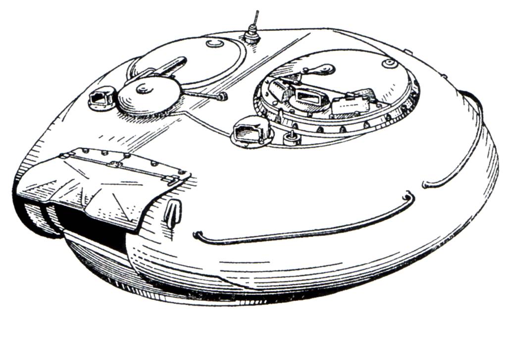
The turret had a very distinct appearance, but in reality, it was merely a reimagination of the hexagonal design of the T-34-85 and T-44 turrets with increased sloping. The turret bustle was shortened which reduced the amount of space available for ammunition, and it gained a wedge shape with a large bevel along its lower half that formed a shot trap. These bevels were included in the turret to ensure that the driver could drive with his head out of his hatch or exit through his hatch regardless of the orientation of the turret.

Like the turrets of the T-44 and T-34-85, this design retained a conventional heavy semicircular mantlet where the gunsight and co-axial machine gun was fitted. The thickness of the gun mantlet can be seen in the cross sectional drawing shown below. At its peak thickness, the gun mantlet reached 200mm. The turret cheeks had a lower thickness but were sloped at a much greater angle due to the curvature of the turret, thus ensuring a higher effective thickness.

The ballistic shaping of this turret was better than the previous versions, but the large shot traps around the turret ring area was considered a huge liability. Other than that, the good angling of the side cheeks of the turret in combination with the well-rounded gunshield provided good protection. The photo below (of an abandoned pillbox turret), provided by Vladimir of Urban3p, shows the curvature of the turret as seen from the gunner's station. The hole at the end is for the TSh-20 telescopic gunsight. By comparing the angle of the wall of the turret to the cannon breech, we can see that the horizontal slope of the turret is quite steep. There is not much in the way of vertical slope, but the turret is rounded. However, the turret ring was protected by rather thin armour in the same way as the T-44 turret, although like the T-44 turret, it had a very low height and was not as exposed as on the T-34-85 turret.

Even though the front of the turret was considerably more resilient than that of earlier medium tank turrets, it was inferior to the front of the hull due to the rather large thickness of the front hull armour and its steep sloping. The shot traps around its front and rear further compromised the integrity of the tank's overall protection scheme.
T-54-2 (T-54 obr. 1949)
To solve the issues with the 1946 turret, the design bureau of plant No. 183 created a new turret design in 1948 with an entirely new egg shape that omitted the front bevel. This new turret design not only provided a weight reduction, but also better protection from all directions. However, the rear bevel shot trap remained albeit with significant reinforcement. The height of the bevel was reduced, and the turret gained an armoured collar around its rear sector that not only protected the turret ring from direct hits but also prevented shell ricochets from reaching it.
In 1949, the revised T-54-2, or T-54 obr. 1949, entered production with the new turret. The thickness of the upper glacis armour was reduced to 100mm. The hull side armour was reduced to 80mm. Despite the decreased mass of the frontal hull armour, the level of protection still met the requirements. Having a thickness of 100mm and sloped at 60 degrees, the upper glacis was equal in thickness to the IS-2 obr. 1944 but the crucial difference was that it was made from RHA instead of a high hardness cast steel. As such, the upper glacis of the T-54 obr. 1949 could resist the 8.8cm Pzgr. 39 fired from a Pak 43 or KwK 43 at point blank range whereas the IS-2 obr. 1944 could only resist this round from a distance of more than 450 meters.
According to a Soviet analysis on the amount of armour required to stop an 8.8cm PzGr. 39/43 armour piercing shell fired from an L/71 Kwk 43 or PaK 43 gun, it was determined that an impact velocity of 1,090 m/s was needed to achieve initial penetration on 100mm of RHA sloped at 60 degrees under the V20 criteria (20% chance of complete perforation). Considering that the muzzle velocity of this shell is 1,000 m/s, the probability of achieving initial perforation was 0%. An impact velocity of 1,160 m/s was required to achieve initial penetration on an 120mm of RHA sloped at 60 degrees.

Besides the reduction in the hull armour thickness, another significant change was the shift to a new turret design with a narrow gun embrasure instead of a traditional gun mantlet. The width of the embrasure was just 400mm wide. The base of the gun barrel is protected by a simple gun mask that only offers protection against artillery shell splinters and heavy machine gun fire. The gun mask also prevents fragments or bullets from jamming the gun elevation mechanism by becoming lodged between the gun breech block and the turret.


The gun mask was mounted to an armoured plate affixed to the front end of the gun breech by four large bolts. The gun mask protects the gun breech at all angles of elevation from direct hits and from bullet ricochets or splatter, but when elevated to a high angle, the lower edge of the gun mask clears the base of the turret and and leaves a noticeable gap as the photo on the right above shows (photo by Vladimir Yakubov). This gap can be large enough to allow even small caliber cannon shells to enter, but a heavily sloped internal armoured plate prevents direct damage to the gun breech or the turret ring. When the gun is level, this armoured plate rests behind the base of the turret as the drawing below shows.

One disadvantage to the lack of a gun mantlet was that a tall slit has to be cut into the armour to accommodate the vertical movement of the co-axial machine gun and the aperture of a telescopic gun sight. As long as a telescopic sight is used, there must be a hole in the armour, but as a gun mantlet moves with the elevation of the cannon, a gun sight aperture embedded in the mantlet only needs a single, small hole. The relatively large slit in the turret of the T-54 increases the size of the weakened zone. Examples of tanks that possess this weakness besides the T-54 include the Chieftain tank, which has a tall vertical slit in the front of the turret for the co-axial machine gun, but the Chieftain bypasses the need for a slit for it's gunner's primary sight by using a periscopic sight.
To seal the gun embrasure from the weather, a rubberized fabric seal was provided.

T-54-3 (T-54 obr. 1951 and onwards)

In the year 1951, the T-54 finally gained its iconic rounded turret. The turret has been described in many ways, from "overturned soup bowl" to "hemispherical". In truth, it is a unique shape with complex angles that cannot be summarized easily. From above, it is distinctly egg shaped. From the side, it is more oblong than round. Only from the front does it resemble a perfectly rounded overturned soup bowl. From a frontal perspective, the thickness of the turret is roughly uniform in the vertical axis although the actual physical thickness of the casting varies. However, the horizonal slope of the turret vastly increases the effective thickness of the turret at the edges of the turret silhouette. Roughly speaking, the thickness of the front of the turret ranges from 200mm at an angle of around 0 degrees at the base of the turret to 70mm at an angle of 52 degrees at the top edge of the turret, where the frontal armour transitions to the roof. The sides of the turret are 160mm thick at the base where the angle of the slope is none or negligible, but the side armour thins down to 115mm at the upper edge of the side where the slope is 45 degrees. However, these values are only nominal as the complex shape of the turret makes the actual thickness values difficult to describe. Overall, the high thickness of the armour increases its efficiency against contemporary armour piercing ammunition. For example, WWII Ballistics: Armour and Gunnery notes on page 25 that a 195mm cast armour plate with a hardness of 220-300 BHN at an angle of 0 degrees is equivalent to 195mm of rolled homogeneous armour with a hardness of 240 BHN against projectiles in the 50-152mm diameter range, meaning that it is essentially equal to an RHA plate of the same thickness. The commonly cited efficiency coefficient of 0.85-0.95 for cast armour relative to rolled armour is only true for thinner plates in the 50-100mm range.

Like the previous T-54-2 turret, there is no gun mantlet and the gun is only protected by a cast steel gun mask. The shape of the gun mask is very similar to the type used on the T-54-2, but it is unclear if the same mask design was carried over directly.

However, cutouts were made in the armour at the slits for the co-axial machine gun and the gunner's telescopic sights now. This created weakened zones where the armour thickness is substantially less than the advertised 200mm. The cutout is shown in the drawing on the right and the cutout for the co-axial machine gun can be seen clearly in the photo on the left. The photo on the left comes from flickr user solipsistnation. The combination of reduced thickness and the presence of a hole in the armour makes the co-axial machine gun port and the gunner's sight aperture especially weak to anti-tank fire.


Production turrets were manufactured by chill casting, but there were issues with casting the entire roof along with the rest of the turret in one piece. To fill in the gap, the roof had to be constructed from two D-shaped rolled steel plates, which were welded onto the cast walls in an automated procedure done by a machine rig. This results in a marginally weaker turret compared to a turret made from a single casting as the roof plates might be ripped off at the weld seams or the seams may burst if the roof was struck by glancing cannon fire. However, using rolled steel plates in this location has the benefit of increasing the chance of a ricochet when struck since rolled steel plates invariably have better ballistic properties than cast steel of the same hardness. An illustration of the chill casting mold is shown below.
The welds joining the hull roof to the side hull, and the welds joining the hull roof to the glacis plates and to the floor and all the welds in between were strengthened in the T-54-3 compared to the T-54-2. The geometry of the fittings between the armour plates was changed to increase the surface area between the joints and thus improve the strength of the seams. This helped to improve the armour integrity of the hull and thus improve protection without changing the thickness of the plates. The hull roof is 30mm thick.
The hull and turret were evaluated against anti-tank guns of a myriad of calibers of both domestic and foreign make. The frontal aspect of the tank had to be proofed against common tank guns like the 90mm M3 of the M26 Pershing and the M46, but it was also tested against the tank's own D-10T and the 85mm S-53 of the T-34-85. As the post war reality showed that American 90mm guns would be the main threat to Soviet armour amd not German 88mm guns, the basic requirements for the ability to resist 88mm shells "with a muzzle velocity of 1000 m/s" (referring to PzGr. 39 shell fired from the 88mm KwK 43 L/71) became very convenient as the tank would not have to be uparmoured to deal with the new expected threat. M82 APCBC/HE-T was obtained via lend-lease, and became one of many foreign-made munitions for use in testing.
The photos below show the armour of a T-54-3 pattern model tested against anti-tank weapons of various calibers. Note that the roadwheels are of the spoked type, indicating that the test vehicle is indeed a T-54 obr. 1951, and not a T-54A or T-54B which were fitted with "star" type roadwheels.
The photo above shows scallops in the turret from various shell impacts and the photos below show the setup of the testing rig for comprehensive turret and hull testing.
The sides of the tank turret and hull were tested just as thoroughly as the front, and with weapons of the same variety. Besides large caliber tank shells, the vulnerability of the sides of the tank to large caliber anti-aircraft cannons like the Soviet Army's own 57mm S-60 was also investigated. It is unknown if the widely used Bofors 40mm L/70 was also tested.
Both the upper and lower glacis plates and the side hull plates are constructed from 42SM armour grade steel. The rear armour plate and the roof plate was made from 49S armour grade steel, and the belly of the tank was made from 43PSM armour grade steel. The cast steel turret was made from 74L CrNiMo armour grade steel, while the two-piece roof welded onto the cast turret was made from 43 PSM steel. The 49S and 43PSM steel plates installed in the roof and belly of the tank was quite thin - only 20mm, so it is quite surprising that these steels are rather soft for their thickness. This table states that 49S and 43PSM have a hardness of only 180-250 BHN. The rule of thumb is that thinner plates are easier to harden than thicker plates, so the plates used in the tank are definitely closer to latter than the former, but even so, that is relatively soft for such thin plates. 42SM and 74L, on the other hand, are medium hardness steels that are technically specified to have a hardness ranging from 285-340 BHN. However, it is reported in the study "Повышение Противоснарядной Стойкости Толстолистовой Серийной Стали 42СМ С Помощью Электрошлакового Переплава" (Enhancement of the Ballistic Resilience of Serial 42SM Steel Using Electroslag Remelting), while the technical specifications call for a hardness within the range of 285-340 BHN, serial 42SM steel plates are actually treated to a hardness ranging from 293 BHN to 311 BHN. These steel hardnesses are optimal for resisting armour piercing rounds for the thicknesses of the given plates.
Foreign appraisals of the steel for the armour of the tank were consistently positive. In the (translated) famous Yugo tests document, for example, it was noted that "T-54A cast parts were 270 BHN (rolled plates were 290 BHN) and were judged to be of excellent quality". From this, we know that 74L cast armour steel has a hardness of 270 BHN, while 42SM has a hardness of 290 BHN. The hardness and thickness of the various armour plates were controlled to offer optimal efficiency against the type of armour piercing shells expected to be used by the perceived enemy.

The sides of the turret slope inwards at 60 degrees and converge at the gun mantlet, giving it a rounded needle-nose shape. This shape is excellent for an all-steel turret from a ballistic point of view, but the effect on internal space in the turret is somewhat negative, which is compounded by the fact that the turret of the T-54-3 is also dome-shaped. The sides of the turret that slope inwards to form the needle-nose shape are 150mm to 170mm thick, thickest as it transitions from the turret front and thinner as it curves round to the back. The rear part of the turret sides, at the commander's and loader's areas, are around 100mm to 120mm thick, thickest at the bottom and thinner as the steel curves towards the top.
If we take a close look at the turret wall behind the gunner's primary gunsight, we can see very plainly how the turret immediately assumes a side slope after the gunsight port.

The photo above also shows that the flat part of the front of the turret is shaped like a right angled triangle. This is the weakest part of the T-54 turret, as it is only sloped in the vertical plane. Aside from the flat triangle, the turret is sloped in three dimensions.
As you can see in the photo, the area behind the gunner's MK.4 periscope is distinctly more curved than the rest of the commander's station. In other words, the flat part of the turret is much narrower than it appears in exterior photos.
VERSUS SPECIFIC AMMUNITION
Penetrating just 147mm at 0 degrees at a thousand meters' distance, M82 was simply inadequate against the T-54. A large portion of the side of the turret has the potential to shrug off a hit from M82 at close range, and the side hull is largely immune at most angles, unless it is struck straight on.
Much later on, the M36 gun became available as well, as nearby Yugoslavia operated 319 M47 Patton tanks. According to the famous Yugoslavian tests, the front of the turret could only be perforated by PzGr. 39-1 APCBC fired from the KwK 43 at a dangerously close distance of 600 meters. The upper glacis was totally immune even from a hundred meters, but the sides of the turret can be defeated at a distance of up to 1750 m.
Fired from the 90mm M3A1, T33 APCBC rounds (shown above) totally fail to defeat the front of the T-54's turret at any range. Shot perpendicularly from the side, the front part of the turret sides can only be defeated at a suicidal range of 250 m. When hot loaded T33 rounds are fired from the higher pressure M36 cannon, the chances improve a bit. The shell is still not capable of getting through the glacis even at a hundred meters, but the front of the turret can now be perforated at 350 m. The frontal part of the side turret can be perforated at 850 m, which is a much more comfortable shooting distance. M304 APDS is mandatory when fighting the T-54, as the front turret can be perforated at 750 m. Nevertheless, the inability to defeat the armour of the T-54 except from the sides can be considered a serious drawback for opposing forces armed with 90mm guns.
M431 HEAT works well at any range on any part of the T-54, but the killing power is low and the shell has fuzing problems on angled parts of the armour. It has a high probability of failing to detonate if it strikes the upper glacis when the tank is angled 20 degrees sideways. The shell may not work properly on the well rounded shape of the turret, especially the top half. Also, M431 was not introduced until the late 50's. Details on the M431 are available here (Link). Fuzing issues with other HEAT rounds were also observed on the T-34-85 during the tests. Of special interest is the performance of the 75mm M20 and the 105mm M27 recoilless rifles. The M310 HEAT round fired from the 75mm M20 fails to defeat the upper glacis armour of the T-34-85 (45mm at 60 degrees) if the side angle was 20 degrees or more and it fails to defeat the upper side hull armour (45mm at 40 degrees) if the side angle was 30 degrees or more. The same result was obtained with the 105mm M27 which could not defeat the upper glacis armour with the M52 round if the side armour was more than 20 degrees. Since the upper glacis of the T-54 is sloped at the same angle as the T-34, the same results can be expected. The sides may be more vulnerable, however, as there are only fuel tanks and stowage bins on the track fenders and no sloped armour plating.
The M82 APCBC/HE-T round packs 200 grams of RDX, but it is largely impotent against the T-54 unless the gunner aimed for the side hull or rear hull and turret. M82 was not included in the Yugo tests, but it is not difficult to predict its performance. According to U.S Army tests detailed here (link), T33 fired from the M3 cannon is capable of defeating the upper glacis (82mm at 55 degrees) of a Panther at a range of up to 1100 yards, but M82 fired from the same cannon cannot repeat the same feat, despite having a capped penetrator. At most, it could deal with the lower glacis - which measured 60mm thick at 55 degrees - at a maximum range of something over 950 yards.
The T-54 offered the next best chance against itself, behind the long-barreled 88mm KwK 43 as the 100mm BR-412B round is capable of perforating the front of the turret at 500 m and the front part of the side turret at 1000 meters. With BR-412D, a better result may be obtained.
The M48 will find itself in a rather bad situation in comparison to the T-54 where hull armour is concerned. It is well known that cast armour is significantly weaker than rolled armour, but the extent is not often grasped by many. In the Yugo tests, testing of domestic M47s have shown that the upper glacis, a 100mm cast steel plate sloped at 60 degrees, can be defeated by BR-412B at a distance of 750 meters even though BR-412B is technically only rated to penetrate 96mm of rolled steel angled at 60 degrees at a point blank distance according to a British evaluation using the same metrics of penetration. The 100mm rolled steel upper glacis of the T-54A is unsurprisingly immune to BR-412B from all ranges. The T-54 can be considered arguably on par with the M48 or the M60 tank in terms of hull armour protection.
There is much more information that can be gleaned from the results of those tests, but only if we pay close attention to detail. The tests involved shooting at the side of the turret from a right angle, but as we know, the turret is sloped inward. If the turret is attacked at a perfectly perpendicular side angle, the front part of the sides of the turret will have a horizontal slope of 30 degrees, thus making the LOS thickness 196mm to 173mm. We know that T33 fired from the M36 cannon is capable of defeating this at 850 m.
However, a shot coming at the turret from a forward 30 degree angle would also have to face between 173mm to 196mm of LOS armour, because the 60 degree inward angle of the turret sides is reduced to just 30 degrees. This means that if the turret is attacked from its forward arc, it may only be as strong as its side in certain parts. In general, the turret becomes more vulnerable as the incident angle increases from 0 degrees to 30 degrees to 50 degrees and so on, up til a point at 90 degrees where it is as vulnerable as it is at 30 degrees. This is a peculiarity of this type of ballistic shaping, and it is not limited to the T-54. The turret of the M60A1 has the same problem, only it is even further amplified because the cheeks of the M60A1's turret are thinner - only 140mm thick. The T-54's turret can be considered to be extremely resilient to anti-tank guns of its time, but it is not without certain weaknesses.
VS 20 pdr
According to British tests, Centurion's MK.3 APDS for the 20 pdr. gun would fail to defeat its own upper glacis (76mm at 57 degrees) at a minimum distance of 4400 yards, or 4023 meters. After the addition of a 44mm weld-on applique armour plate, the distance of immunity was decreased to just 850 yards, or 777 meters. This means that MK. 3 APDS can penetrate less than 120mm RHA angled at 57 degrees at 777 meters, and less than 76mm at 57 degrees at 4023 meters.
According to Swedish archive documents shared by renhanxue, owner and administrator of the Swedish Tank Archives website (tanks.mod16), 20 pdr. APDS (most likely MK. 3) can penetrate 240mm of vertical plate at 500 m, and 95mm at 60 degrees at 1000 yards (914 m), and it fails to penetrate 122mm angled at 60 degrees at 500 m. This is congruous with the aforementioned tests. The hardness of the plate used is unknown. However, the drop in penetration performance is between 4400 yards and 1000 yards is suspiciously small for an APDS round. It is possible that the Centurion's rolled steel plates are softer than the test plates used during the Swedish tests.
Taken all together, this means that using MK. 3 APDS, a Centurion Mk. 3 should have the ability to defeat the upper glacis plate of a T-54 only from below 900 meters. This makes the Centurion the best performer among all of its Western peers in a hypothetical face-off against Soviet T-54s.
Let's see how MK. 3 does against shallowly sloped plates:

So, MK. 3 can confidently defeat 150mm RHA angled at 30 degrees at about 1750 yards, and pierce 120mm RHA angled at 25 degrees at up to 2250 yards. This would allow it to perforate the base of the T-54 obr. 1951 turret in the region around the gun mantlet, but the frontal arc of the turret is still capable of resisting a hit from MK. 3.
According to Swedish test data provided by renhanxue, 105mm L28 penetrates 200mm RHA at 30 degrees at 1500 m, and 140mm RHA at 55 degrees at 900 m. On the Tank-Net forum, renhanxue states that the British give a penetration value of 120mm RHA at 60 degrees at 1000 yards for L28. Overall, this means that the turret of the T-54 is vulnerable from combat ranges of 1500 meters and beyond, so the 105mm L7 gun is an effective countermeasure against the T-54 in a frontal attack.
Additionally, any evaluation of the T-54's survivability is not complete without also reviewing the value of its relatively small silhouette. Being quite small for a tank, the T-54 is easy to conceal in vegetated areas. The small surface area of the tank also makes it less time consuming to camouflage.
Although it is an aspect of the T-54 design that is often criticized, a small silhouette was not only coveted by Soviet tank designers. It was a common goal of practically every major military power that was influenced by statistical probabilities calculated from years' worth of combat data. For example, the height of the M60A1 was recognized as excessive and the M60A2 introduced a low-profile turret design to minimize the projected area of the turret while maximizing protection.

Metal-Polymer Armour

The add-on armour featured on the T-55AM and its variants is referred to as metal-polymer armour blocks. This type of armour has already been covered in Tankograd's T-62 article. It would be pointless to repeat it all here, so please head over to the T-62 article to read more. However, the unique geometry of the turret of the T-54 means that the spacing between the turret and the add-on armour blocks is not the same as on the T-62, which is a nuance worth examining.
As mentioned earlier, the turret of the T-54 had a variable thickness and had a very complex range of sloping angles due to its rounded shape to ensure that the entire height of the turret had an equal thickness of steel. This was designed so that the turret could attain a uniformly high level of protection against steel full caliber shells and APCR rounds with tungsten carbide cores. The shape of the metal-polymer armour blocks on the T-55M and T-55AM turrets was therefore designed accordingly.
According to Soviet drawings, the total thickness of turret armour including the "Brow" armour blocks amounts to 500mm when measured at the center of the block. At the top of the armour block, the thickness of the cast steel front plate decreases but the metal-polymer composite armour increases and the air gap behind it also increases to compensate. At the bottom of the armour block, the cast steel front plate of the "Brow" armour block is thickest but the metal-polymer composite has its smallest thickness, as does the air gap. Due to the complexly differentiated thickness of the armour elements, the total LOS thickness of the turret differs at the locations where the "Brow" armour block is present.

The variable thickness of the cast steel front plate can be seen clearly in the photo below, taken from Andrei Tarasenko and originally uploaded to his blog. The subject of the photo is a Czechoslovak T-55AM2, but the armour is identical to the Soviet T-55M and T-55AM.

At the top half of the armour block, the cast steel front plate has a thickness of 71mm, the armour is sloped at an obliquity of 30 degrees and the total thickness of the armour is 280mm. At the bottom half, the cast steel front plate has a thickness of 85mm and the entire armour block is sloped at an obliquity of 15 degrees.


The size of the air gap is known thanks to measurements provided by Georg Stark and published in Paul Lakowski's "Modern Armour". It is now known that "Modern Armour" uses very old estimates and figures, but some of the information, like the photo and sketch below, is accurate as it was measured directly on the tank in question.

As the sketch shows, the air gap between the metal-polymer composite block and the turret ranges from 50-60mm at the bottom to around 200mm at the top, directly corresponding to the thickness of the metal-polymer composite block itself. At the top of the armour block where the air gap is 200mm, the turret armour has a thickness of 100-110mm and is sloped at 54 degrees for a LOS thickness of 178mm and the "Brow" armour block itself has a LOS thickness of 323mm. By adding up the cumulative thicknesses of the "Brow" armour block, the air gap and the turret armour, it is calculated that the armour array has a total thickness of 659mm at this location. Using these methods, it is determined that the at the bottom and middle of the turret, the LOS thickness ranges from 480mm to 500mm but it reaches up to 660mm at the top. The turret armour itself remains at a uniform thickness of 170-180mm at these zones.
The presence of an air gap behind the armour array gives room for KE projectiles to break apart as the buildup of internal stresses from the penetration of the steel front plate and the moving internal plates is suddenly released, thus magnifying the effect of the armour. For shaped charge jets, the air gap gives room for disturbed jet particles to disperse such that they do not contribute to the total penetration depth from the residual jet tip.
The belly armour was enhanced with rudimentary spaced armour plate welded onto the hull. Six 20mm steel plates were welded onto the front half of the tank belly with the proper spacing of 80mm ensured by a steel frame. Unlike more modern mine and IED protection kits, there is no low-density filler between the spaced plate and the tank belly so there is little blast attenuation aside from the spaced 20mm plate. The main function of the spaced armour would be to prevent the tank belly from being breached by an explosion.
The drawing on the left below shows the tank's escape hatch with its spaced plate armour and the drawing on the right below sows the spaced belly armour kit from a profile view.


The separate spaced plate sections can be seen below. There are ports built into the armour for drainage plugs.

NBC PROTECTION
As the T-54 was formulated during the closing years of WWII and was only finalized a few years after its conclusion, no considerations were made for the effects of nuclear destruction. As part of tests carried out between 1952 and 1953 to determine the effects of nuclear weapons on various ground equipment, including tanks, the T-54 tank was exposed to a nuclear explosion from various distances. As it turned out, even at large distances, the turret could be displaced by the sheer power of the nuclear winds even when the turret was locked in the travelling position, causing the gear teeth around the turret ring to break and render the tank unserviceable. As a result of these tests, the turret locking mechanism was strengthened, so that even at around 300 meters' distance from the detonation of a 2 to 15 kiloton bomb, the tank remained serviceable.
However, it was discovered in subsequent tests that at distances of up to 700 meters, animals (rabbits, dogs) standing in for the tank crew died immediately from the shock wave and overpressure of the blast. As a result of these findings, the requirements for a comprehensive anti-nuclear protection suite for the T-54 were drawn up, and in 1956, the KB-60 design bureau from Kharkov finalized a "PAZ" (Nuclear Protection System) complex and sent the technical documentation to the Uralvagonzavod tank factory for implementation.
The T-55 was the first Soviet medium tank to feature an NBC protection system. It was an advanced collective type system with automatic and semi-automatic operating modes. A gamma radiation sensor was used to detect the detonation of a nuclear bomb and initiate countermeasures before the shockwave could reach the tank. The system could react 0.3 seconds after detecting a spike in gamma radiation. All openings in the tank would be automatically sealed by heavy steel wedges activated by explosive squibs. The engine and the cooling fan would be stopped, and the armoured louvers over the engine deck would be closed, all done automatically.

The ventilator intake fan on the turret roof lacked a filtration unit and was insufficiently powerful to create an overpressure inside the tank, and there was no additional space to add these necessary features. As a result, it was replaced by a new ventilator intake system that included a supercharged blower. The supercharger drum is placed right beside the co-axial machine gun, in front of the loader. Not only was it capable of producing an overpressure inside the tank to prevent foreign particles from seeping in, the filtration system could also remove chemical and biological agents, though only when activated, either manually or automatically. In normal operation, the powerful compressor fans are not used, and the ventilation system performs the same basic function as the old dome ventilator.
The T-55A obr. 1967 provided an additional layer of security from the harmful effects of a nuclear explosion by including a special anti-radiation lining. The anti-radiation material is a lead-impregnated polymer composite textile that is layered and cut into the desired form before it is installed on the surfaces of the tank. It is designed for absorbing gamma radiation - the most dangerous form of radiation as it can penetrate even relatively large thicknesses of steel - but it can also perform a secondary function as a spall liner when present in sufficient thickness.
The anti-radiation lining is secured onto the internal surfaces of the fighting compartment by bolts. They mainly cover the areas of the tank where the armour thickness is lower and therefore less effective at attenuating gamma radiation and neutrons. The turret ceiling is completely covered by the lining and most of the turret rear and sides are covered. Even the hatches have a layer of anti-radiation lining.


The commander's cupola and loader's cupola on the T-55A both had relatively high radiation permeability due to their relatively low thickness of armour. As such, a large thickness of anti-radiation lining was needed to ensure a sufficient level of protection, but this thickness was too large to be practical as a lining on the internal surfaces of the cupolas. Instead, the anti-radiation material was installed outside the cupolas in the form of prefabricated conformal blocks and given a sheet steel shell to protect it from the weather and from the initial blast and heat of a nuclear explosion. Anti-radiation material was also added to a small strip of the turret roof joining the two cupolas.

The large thickness of the anti-radiation blocks on the loader's cupola can be seen in the two photos below. If this amount of material was used as an internal lining instead, it probably be so thick that it may constrict the size of the loader's hatch and it would certainly severely restrict his headroom.


The commander's cupola received similar treatment. However, the commander's hatch and cupola roof has a noticeably larger thickness of external anti-radiation cladding compared to the loader's hatch, and this is because a lining would have intruded much more into the commander's available headroom than for the loader, who is not confined to a fixed position underneath his cupola.

The driver's hatch also received an anti-radiation cladding.
ESCAPE HATCH
The T-54 has an escape hatch. It is located behind the driver's seat. It is held in place by four locks. Once all four have been disengaged, the hatch drops down, allowing the crew to crawl out. It is much easier said than done, and it will be nearly impossible to do a quick escape from a hatch of such small size, but having a hatch presents unique tactical opportunities as the crew can exit the tank without being seen by the enemy.
DRIVER'S STATION


The driver's station in the T-54 was a departure from the T-34 driver's station in that it had less headroom due to the significantly shortened hull, but the driver's comfort and visibility improved because the periscopes were relocated from a hatch on the upper glacis plate to the hull roof. This meant that the driver could be seated in a far more natural posture while driving. There were also other ergonomic improvements were added for the driver's benefit, such as handlebars built into the periscopes for the driver to hold on to as he ingresses or egresses from his station. The driver's station changed very little throughout the evolution of the tank, as exemplified by the two photos above. The photo on the left shows a T-54A and the photo on the right shows a T-55. The only major difference is the absence of a bow machine gun on the latter tank.
We have already examined most of the components of the driver's station in Tankograd's T-62 article. As the driver's station in a T-62 is almost identical to one from a T-55, there is no point to repeat it here. Please head over to the T-62 article. However, there are some small historical details that uniquely belong to the T-54.
The design of the driver's hatch of the T-54 was finalized on the T-54 obr. 1947 and it was retained throughout the production life of the tank series. The design is shown in the drawings below. The thickness of the hatch was equal to the hull roof: 30mm. As mentioned before in the article when examining the ventilation system of the T-54, the driver's hatch had a small ventilation porthole designed to work in conjunction with the ventilation exhaust fan at the back of the fighting compartment, in the engine compartment bulkhead. Besides that, there was a layer of padding on the underside of the center of the hatch to protect the driver's head from a hard knock, and the rim of the hatch opening was lined with rubber on both sides to seal the hatch from the weather and to provide some protection for the driver's head. These details can be seen in the drawings below.
One side of the hatch opening is slanted which was necessitated by the overhang of the turret over the turret ring. The dimensions of the hatch opening are not particularly large but it is reasonable. It is particularly important to note that the width of the hatch is 486mm which is substantially more than the average shoulder width of an average Soviet Army conscript, so in general, the size of the hatch can be considered sufficient for a tank driver even when wearing winter clothing.


The driver's sat in a bucket type seat. It had bolsters on the sides and a well-padded cushion and backrest. It could be adjusted in height, with the tallest setting meant for driving with the driver's head outside the hatch. The backrest could be adjusted between just two angles of recline, which is rather unfortunate. However, the backrest can be easily folded fully backward or forward in order to allow the driver to freely move into the fighting compartment or evacuate the tank via the escape hatch behind him.

The periscopes of the T-54 also deserve some mention. Originally, destroyed periscopes were almost impossible to remove if a powerful shell struck the armour in front of it as the mounting piece would usually be damaged in a most inconvenient way. This was solved in 1953 by using a heat-treated mounting piece of a higher grade of steel, increasing the strength of the welds and by thickening certain components.
In 1951, the TVN-1 infrared night vision driving periscope was introduced along with an infrared headlight on the T-54 obr. 1951. With the help of the tank commander who was provided with the new TKN-1 night vision monocular periscope, the driver of the T-54 gained the ability to navigate at night more stealthily than if conventional white light headlights were used and tank units could march more confidently at night. When the more capable TVN-2 night vision periscope became available in the late 1950's, the TVN-1 was phased out in favour of the newer type. The two images below show TVN-2 periscopes installed in the appropriate periscope slot.


For a more detailed examination of the night vision devices, please head over to Tankograd's T-62 article.
MOBILITY
The mobility characteristics of the T-34-85 were largely retained, but it is somewhat worse than the T-44 due to the large difference in weight. The T-34-85 had a combat weight of 32 tons and with a gross engine output of 500 hp, the tank ostensibly has a power-to-weight ratio of 15.6 hp/ton. The T-44 had a combat weight of 31 tons and an uprated V-44 engine with an output of 520 hp, so it had an increased power-to-weight ratio of 16.8 hp/ton. However, the net power available at the drive sprockets of the T-34-85 is 390 hp after all the power deductions from the cooling system, generator, and other auxiliary equipment are made. The actual power to weight ratio is 12.2 hp/ton.
Having a gross output of 520 hp, the V-54 engine gave the T-54 obr. 1949 a nominal power-to-weight ratio of 14.65 hp/ton, but the net power is 430 hp so the real power-to-weight ratio is actually 12.2 hp/ton. When the gross powers are compared, the power-to-weight ratio of the T-54 obr. 1949 is 6.3% lower than the T-34-85, but when the net powers are compared, the two tanks are equivalent.
The engine was installed transversely in the hull and was connected to the transmission by a transfer case that contained the main clutch.

One of the immediate benefits of the transverse engine position is the increased power transmission efficiency gained by omitting a bevel gear to transmit the driveshaft power to two axles, which is necessary when the engine is installed longitudinally. Alone, a bevel gear incurs a power transmission loss of 4%, as the drawing below shows. The drawing was taken from page 432 of the Soviet tank design handbook "Tank" (1954).

The transmission was quite compact and its external appearance was similar to the transmission of the T-34. Above it were the water and oil radiator packs and the accompanying radiator fan. This layout made it possible to greatly decrease the volume of the engine compartment by decreasing its length, and most importantly, this design solution did not have any caveats.
V-54
The T-34-85 had a top speed of 55 km/h, while the T-44 had a top speed of 51.1 km/h. The first mass-produced model, the T-54 obr. 1947 had a restrictive top speed of just 43.5 kph. The V-54 was slightly underpowered for the T-54 obr. 1947, so the top speed had to be compromised by adjusting the gearing ratios in the gearbox to preserve the acceleration characteristics of the tank. The T-54 obr. 1949 and the definitive T-54 model, the T-54 obr. 1951, finally settled on a slightly more modest weight which permitted a top speed of 50 km/h to be achieved.
Fuel is delivered by a direct injection system. The engine has a 14-15:1 compression ratio.
Not all of the engine's power is used to propel the tank as some power must be transferred to the centrifugal radiator fan for the tank's cooling system, the air cleaning system, and the G-73 electric generator for the tank's electrical systems. The net power available to propel the tank is 430 hp. This constitutes 82-83% of the gross power.
V-55

The V-55 is a modification of the V-54 engine with an increased output. It generates a maximum power output of 580 hp at an engine speed of 2,000 rpm and a maximum torque of 2,254 N.m at an engine speed of 1,200-1,400 rpm.
Thanks to the increased power of the V-55, the gross power-to-weight ratio of the T-55 increased to 16.1 hp/ton.
The added power comes from a better optimized compression ratio of 15:1 ±0.5 and an improved fuel injection system. The V-55 was paired with a new and improved VTI-4 air filter which helped by reducing the power loss in extremely dusty environments.
Aside from the increased automotive performance, the new engine was more robust and reliable. It was delivered to the Soviet Army with a warranty of 350 cumulative hours of engine operation.
Due to the power allocated to the G-5 electric generator for the tank's electrical systems and the addition of an AK-150 air compressor, the net power available to propel the tank is only 480 hp. This constitutes 82.76% of the gross power.
In the Soviet tank design handbook "Tank" (1954), it is stated on page 432 that the energy loss from friction from a mechanical (manual) gearbox is 6%. From there, the power is transmitted to the final drives, where an additional power loss of 1% is incurred. With this high level of efficiency, most of the net engine power is transmitted to the drive sprockets with only a small amount becoming heat. In turn, this indirectly increases the power available to propel the tank as it reduces the amount of power that must be allocated to the cooling system.
The superior gearbox and steering system of the T-54 enabled the tank to get more out of its 520 hp engine by allowing the driver to shift gears much more quickly and also to steer more precisely and with much less effort. Moreover, the new super-compact dry plate clutch transmission enabled the T-54 to retain the agility of the T-34-85 despite having a worse power-to-weight ratio, especially at higher speeds. This is because the T-34-85 was steered via the clutch-and-brake system which robbed the tank of some of its speed with each turn. The top speed and acceleration of the T-54 when travelling in a straight line was worse compared to its predecessor, but when travelling on actual roads or when moving cross-country, the T-54 was comparable.
According to the official figures presented in manuals, the average speed of the T-34-85 reaches 30 km/h on paved roads and reaches 25 km/h on dirt roads whereas the T-54 obr. 1951 reaches an average speed of 30-33 km/h on paved roads and 20-25 km/h on dirt roads. It is reasonable to assume that these figures were derived from a standardized test where both tanks ran the same course at Kubinka under the same conditions albeit at different points in time, so in all likelihood, these average speed figures should be directly comparable. With that, it can be seen that even though the T-54 cannot reach a top speed as high as the T-34-85, it did not suffer in terms of mobility in realistic conditions where the tank must be navigated through a course that involves maneuvering rather than simply driving in a straight line. The uprated engine of the T-55 tank allowed it to achieve an average speed of 32-35 km/h on paved roads and 22-27 km/h on dirt roads, thus surpassing the T-34-85 by a small margin.
TRANSMISSION

The T-54 used a 5-speed manual transmission with a syncromesh gearbox. In the T-54 gearbox, the speeds ranging from the 2nd to 5th are controlled using the synchromesh system, but the 1st gear and the reverse gear still used the less advanced constant mesh system. The lack of a synchromesh system on the 1st gear was typical of old synchromesh gearboxes and it was not a real disadvantage for the T-54 because the driver only engages the 1st gear while the tank is motionless, and when the vehicle is motionless, a synchromesh system is not necessary. It was the same for the reverse gear, and in fact, modern vehicles with manual gearbox typically don't use a synchromesh system in reverse.
The use of a synchromesh means that driver does not have to use double declutching for gear changes. As there was no need for double declutching, the time required for gear changing is reduced and the amount of driver experience required to drive the tank was also reduced. Because of these advantages, practically every modern passenger car with a manual transmission use a synchromesh system. For comparison, T-34 tanks produced since 1943 used a 5-speed unsynchronized gearbox with a constant mesh system. That means that the T-54 gearbox had a serious advantage over the gearboxes of late production T-34 tanks such as the T-34-85.
Additionally, in the Polish book "Teoria ruchu pojazdu gąsienicowego" (Theory of tracked vehicle movement) written by Zbigniew Brudziński, it is stated that for a synchromesh gearbox, a gear change typically requires 1.0 to 1.5 seconds. For comparison, a gear change in a unsynchronized constant mesh transmission typically requires 1.5 to 2 seconds. Moreover, Brudziński writes that in an unsynchronized sliding mesh transmission such as the 4-speed gearbox used in early T-34 tanks (up until 1942), a gear change requires 2 to 3 seconds.

The drawing below shows a top view of the transmission with its kinematic components and connections. The T-54 transmission has 3 parallel shafts located longitudinally relative to transmission body. Due to the transverse mounting of the gearbox, the shafts are located transversely relative to the tank hull. The First shaft works as the power input. It receives power from the engine through an intermediate power transfer mechanism and main clutch (which are located between engine and gearbox). The first shaft transmits power to the second shaft, and the second shaft acts as an intermediate to transfer power to the third shaft, which is the main shaft.

The gears on the second and third shafts are paired together. The specific pair of gears used for power transmission from the second shaft to third shaft depends on the gear shift lever position. The synchronizers used for engaging gears are located on the third shaft. The third shaft transfers power to the steering mechanism.
The main clutch is a multi-disc dry clutch. It is is located between engine and gearbox, or more precisely, it is between the gearbox and intermediate power transfer mechanism. The main clutch is used for declutching the gearbox from the engine, like in a typical passenger car with manual gearbox. For declutching, the driver uses the clutch pedal.
T-54 uses a double-stage epicyclic steering mechanism. Each track has a separate steering mechanism with separate epicyclic steering units. The left steering tiller operates the left epicyclic unit, and the right tiller operates the right epicyclic unit. The two systems are completely isolated, so pulling on one steering tiller has no effect on the other. In both epicyclic units the ring gear works as the power input - power from the engine is delivered to the ring gear via the driveshaft from the gearbox and it transfers power into the rest of the gears. The planet carrier works as the output - it gets power from the ring gear (through the planets) and transfers power to the final drive, which transfers the power to the track via the drive sprocket.
In the T-54, the steering tillers have 3 main positions. The 1st position allows the track to move at its full forward speed, the 2nd position generates a reduced track speed by engaging a reduction gear, and the 3rd position is used for track de-clutching and braking. When driving the tank, if the driver changes the right tiller position from 1st to 2nd without changing the left tiller position (still in the 1st position), the speed of right track is decreased but left track still moves at its full forward speed. This causes the tank to turn to the right.
If the tiller is in the 1st position, the clutch of the steering mechanism keeps the sun gear and planet carrier connected, so that one rotation of the ring gear produce one rotation of the sun gear and one rotation of the planet carrier. If the tiller is in the 2nd position, the ring gear is disconnected from the sun gear, and the sun gear is braked by a small internal brake. Thus, the planets rotate around the sun gear and one rotation of the ring gear is faster than one rotation of the planet carrier in a ratio of 1.42. Changing tiller position from the 1st position to the 2nd position decreases the planet carrier speed, but increase the torque on the planet carrier. As a result, the speed of the drive sprocket is reduced but its torque is increased. If the driver puts the steering tiller on the 3rd position, the sun gear is disconnected from the planet carrier but the sun gear is not braked. Instead, the planet carrier is braked by the main brake. In this tiller position the track is braked and de-cluched, so it is disconnected from the drivetrain.
Regardless of the turning direction, the faster track moves at its full forward speed while the slower track has a lower speed than during a forward ride, and the hull moves at a lower speed than during a forward ride as it turns. In Polish terminology, this idea is categorized as a "second group steering mechanism". Steering mechanims which are included into the second group may be based on side clutches or on epicyclic gearing. Second group steering mechanisms include systems that do not feature regenerative steering (side clutches) and systems which feature regenerative steering (epicyclic gearing).
When the driver changes the steering tiller from the 1st position to the 2nd position, the track speed is decreased but the torque delivered to the track is increased. As such, the T-54 steering mechanism can be used as a reduction drive that may be used when additional torque is needed. For example, if the driver sees a steep hill, he can pull both tillers from the 1st position into the 2nd position to increase the torque delivered to the tracks to propel the tank until it reaches the top, whereby the driver returns the tillers to the 1st position. This method of torque boosting cannot be used for prolonged periods. According to the Polish army "Podręcznik czołgisty" (Tanker handbook), the driving distance should not be greater than 100-150 meters when using this method. This is enough for climbing hills, extricating another tank from a ditch by towing, knocking over obstacles, or performing some other operation that requires higher torque.
There are two main turning radii. If the driver wants to gently turn the tank, the first turning radius of 9 meters is used. With both tillers starting in the 1st position for normal forward motion, the driver pulls one tiller to the 2nd position while keeping the other on the 1st position. In this case both tracks move forward relative to the hull but with different speeds. When the first turning radius is being used, the T-54 steering mechanism operates with regenerative steering. Regenerative steering means that during a turn, power is transferred from the slower track into the faster track. That means that the faster track not only receives power from the engine, but also from the slower track. As such, a tank with regenerative steering requires a lower engine power to turn compared to a tank that does not feature regenerative steering idea. The turning radius of the tank does not depend on the selected gear. The drawing and citation below, taken from the Polish book "Teoria ruchu pojazdu gąsienicowego", details the regenerative steering concept in the T-54 steering mechanism:

From the book, translated by AKMS of the milimoto blog:
"Power which is transferred from the epicyclic gear of the slower track into main shaft of mechanism, circulates inside closed circuit: axle of faster track sprocket wheel - final drive - vehicle hull - final drive of slower side - epicyclic gear of this side of vehicle - main shaft of mechanism - epicyclic gear of faster side - final drive - axle of sprocket wheel of faster vehicle side. Power transferred from slower track into faster track is called "regenerative steering". This is the recuperation power, which must be additionally generated by the engine if power were not transferred from the slower track into the faster track"
In other words, in T-54, when the first turning radius is being used, power is transmitted from the engine into the faster track through the gearbox, the faster track moves the hull, hull movement propels the slower track (hull movement powering slower track), and power is transferred from the slower track into the faster track. This situation is visible on the drawing above.
The transmission permits the tank to execute pivot turns but not neutral turns. A pivot turn is where one track is driven forward or rearward while the other track is stopped with the tank turning around the stopped track, and a neutral turn is where both tracks are driven in opposite directions with the tank turning around the reversing track. When performing a pivot turn, the tank is using its second turning radius. To execute a pivot turn in a T-54, the driver must have one tiller on the 1st or 2nd position while pulling the other tiller to the 3rd position. The tiller placed in the 3rd position causes the corresponding track to be declutched and braked, thus immobilizing it. The tank rotates around the immobilized track, effectively steering the system via the traditional clutch and brake method. In this case there is no regenerative steering. If the propelling track is driven with the steering tiller in the 1st position, the tank performs the pivot turn at its maximum speed for a given gear. When the 2nd position is used, the torque delivered to the propelling track is increased while its speed is decreased and as such, the tank turns more slowly but more firmly.
Other than a "second group steering mechanism" like in the T-54, Polish terminology also includes the "first group steering mechanism" category. First group steering systems are based on a differential or multiple differentials. In a first group steering mechanism, pulling a tiller decreases the speed of the corresponding track while automatically increasing the speed of the opposite track compared to its normal forward speed. That means that during a turn, the hull moves at a speed equal to its full forward speed. Inside first group of steering systems, there are systems which don't use regenerative steering (braking differential) and systems which use regenerative steering (controlled differential).
Generally, steering mechanisms belonging to the second group produce a lower hull speed than first group steering mechanisms during a turn, but on the other hand, the load on the engine during a turn is lower when a second group steering mechanism is used compared to a first group steering mechanism. However, it should be emphasized that this is a generalization and there may be exceptions.
In the T-54 steering mechanism, the main brake is used not only for pivot turns (one tiller in the 1st or 2nd position, another tiller in the 3rd position), but also for vehicle braking during forward motion. The driver can use the steering tillers for braking during forward motion by pulling both tillers to the 3rd position. Of course, if the driver puts both tiller into the 3rd position, the tracks are not only braked but also are disconnected from drivetrain. If driver wants to brake the tank without de-clutching the tracks, he can step on the brake pedal instead. In some Soviet tanks with similar steering mechanism, a brake pedal is not provided. For example, Soviet heavy tanks like the IS-2, IS-3 and T-10 lack a brake pedal. The drivers of these tanks must pull both tillers to the 3rd position to brake, and the side effect of this is that the driver cannot brake the tank without de-clutching both tracks.
Driving a T-54 is less fatiguing than driving a T-34. Thanks to a hydraulic assist mechanism, the pulling force on the steering tillers is 12 kilogram-force (kgf), compared to around 30 kgf in a typical T-34 (27-36 kgf for a T-34-85). Additionally, in T-54, the clutch pedal is also hydraulically assisted and it also requires 12 kgf to depress. In a T-34, the maximum acceptable force on the clutch pedal is 25 kgf. The data for the T-54 comes from the Polish "Tanker Handbook", and the data for the T-34 comes from a Soviet test and Polish manual from 1961 (T-34-85M manual).
The transmission casing is made from cast aluminium. It is air-cooled by the centrifugal cooling fan. The power takeoff unit that transfers power from the engine to the tank's auxiliary systems is on top of the transmission casing. The power takeoff unit connects directly to the first shaft of the gearbox which receives power from the engine, and there is no intermediate gearing so the amount of power supplied to the power takeoff unit changes only when the output of the engine itself changes. The block splits the power between three smaller drive shafts. One goes to the AK-150 air compressor (if installed), another is connects to the centrifugal cooling fan, and the third connects to the radiator coolant pump.

The three L-shaped protrusions on the top of the transmission casing are part of the gear shifting system. They are connected to the gear shift lever. The three loops on the corners of the transmission casing are lifting eyes, to be used with a winch to lift the entire unit out of the tank's engine compartment such as shown in the photo below.

Like many tanks preceding it, the T-54 has the option of using compressed air to start its engine. There are two 5-liter air canisters mounted in the driver's station that are used to inject air into the cylinders of the engine, forcing the pistons into motion. This method is harsh on the engine, but dependable. Starting the engine in the summer is usually done electrically, but in the wintertime, the electric starting system may not be reliable due to piston lockup, so using air is necessary. In the harshest weather conditions, with the most poorly maintained T-54, starting the engine will require a combination of both methods simultaneously.
However, like the T-34, the compressed air tanks in a T-54 are not refilled automatically, so the reserves of compressed air is limited. This was changed in the T-55, which was equipped with an AK-150 V-shaped air compressor. The AK-150 is a typical two-stage reciprocating compressor, and like any other compressor of its type, the second stage piston is shorter than the first, and the two are linked by a cooling tube for the forced air cooling system used to regulate the heating of the piston cylinders during normal operation. The compressor is powered via an input shaft from the engine that is independent of the gearbox, thus allowing it to continue running even if the tank's gearbox is set to neutral. When it is in normal operation, the compressor uses 1.1 to 2.2 kilowatts of power (1.47-2.95 hp) depending on the engine speed. As such, the compressor would reduce the net power delivered through the transmission by an average of 2 hp when it is running.
The AK-150 compressor can be seen in the photo of the exposed engine compartment above, partially obscured, and the pneumatic starter system of the T-55 is illustrated in the drawing below.


It must also be said that the T-54 is extraordinarily light compared to its foreign counterparts. Weighing in at only metric 36 tons dry, it is lighter than a generic Centurion tank (52 metric tons) by an entire 16 tons, and lighter than an M48 tank (45 metric tons) by 9 tons, and despite this, it is comparable in most respects and manages to achieve superiority in others. The light weight of the tank enables it to not only exploit bridges intended for light loads, but to also use pontoon bridges and scissor bridges with impunity, as there will be a large load surplus. A large convoy of T-54 tanks may cross a pontoon bridge without needing to take turns.
The T-54 exerted a ground pressure of 0.8 kg/sq.cm, whereas the newer and heavier T-55 exerted a ground pressure of 0.81 kg/sq.cm.
SUSPENSION

Like the T-44 before it, the T-54 used torsion bars instead of the famous Christie spring suspension of the T-34. The tracks were unsupported and ran directly on top of five large diameter rubber-rimmed roadwheels. The drawing above shows the suspension of a typical T-54 with the shock absorbers behind the first, second and last roadwheels on either side of the hull clearly visible.


Due to the lack of space above each roadwheel swing arm owing to the lack of support for the returning track, it was not feasible to install a conventional linearly actuated hydraulic shock absorber, so a compact vane-type rotary hydraulic shock absorber was installed. The shock absorber arm is joined to the roadwheel arm by a rod.
The rotary shock absorber contains four chambers separated by two vanes with constricted openings for hydraulic fluid to pass through. Vertical motion of the roadwheel swing arm deflects the lever arm of the shock absorber, transforming linear force into torque which is applied to the vane rotor. The rotary motion of the vanes displaces the hydraulic fluid from the high-pressure chamber to the opposing low-pressure chamber via the vane opening. The restriction of fluid flow through a small opening creates a resistance to motion, converting kinetic energy into thermal energy, thus damping the force applied by the roadwheel.

The torsion bars were swapped out for better ones made by electroslag remelted (ESR) steel in the T-55AM modernization and the variants thereof. One reason for this upgrade was simply the desire the improve the mobility of the tank to a more modern standard and improving the quality of the ride, but another reason was the added weight of the tank from the add-on "Brow" armour. The superior steel of the new torsion bars combined with the heavier mass of the modernized tank improved the damping of vibrations.
OMSh tracks
As with earlier Soviet medium tank tracks, the T-54 uses OMSh tracks. OMSh stands for open metal-pinned tracks. The single-pin track links are held together with bare metal pins which are only secured on the inner end of the track by an oversized head. There are no clips or fasteners to retain the pin on the other end of the track, so when the tracks move, the pins gradually come loose and eventually worm their way out of their slots, but only in the direction of the hull. A steel ramp is welded onto the side of the hull just next to the drive sprocket to knock these loose pins back into the track.
The T-54 obr. 1947 used a proprietary OMSh track design with a width of 580mm that was not carried over to later T-54 models. Beginning with the T-54 obr. 1949, a new OMSh track design was implemented and this came to be the standard design for the T-54 family and its derivatives for the next two decades. These OMSh tracks can be easily identified by the distinctive loop at the end of each track link. The track links are made from cast steel. There are 90 links on each side. The track width remained the same at 580mm and the track pitch is 137mm.


The requirement for the lifespan of the track was fulfilled by the original OMSh track design of the T-54 prototypes, four years before the new OMSh track for the T-54 obr. 1949 was developed. Recall that the T-54 was developed under a set of six requirements, the fifth being: "Develop a robust track and track pin (increase track life to 3,000 km)". Testing in 1946 revealed that the T-54 prototype drove 20,000 kilometers and wore out 6 pairs of tracks, equating to an average lifespan of 3,333 kilometers per track, thus exceeding the original requirements by an average of 11.1%.
There were no rubber bushings and no rubber pads on the inner surface of the track links. Furthermore, the open design of the tracks meant that sand and dust could slowly accumulate inside the gap between the track pin and the track link socket. The abrasion from these foreign objects could wear out the track pins which could make them more susceptible to breaking, thus increasing the probability of the tank throwing a track when performing a hard maneuver of some kind. The deficiencies of open-type tracks were recognized and work was done to implement new track designs with an increased lifespan.
RMSh

To improve the lifespan of the tracks, a new RMSh track design was developed by the Omsk Transport Engineering Plant with development concluding in 1962. Beginning in 1966, these new RMSh tracks were fitted to new-production T-55 tanks on a mass scale and the new tracks gradually replaced old OMSh tracks on existing T-54 and T-55 tanks as they wore out during normal use. However, the new track did not become a common sight until much later because large stockpiles of OMSh tracks had been accumulated in the Soviet Army and there was a plentiful supply of spares.
RMSh stands for rubber-lined metal tracks. The tracks have the same width of 580mm as the previous OMSh track design. The track pitch is 137mm, which is also exactly the same as the previous OMSh track design. The track pins are hexagonal and fit into the rubber-lined track pin sockets in the track links and are fastened at the ends with hexagonal nuts.

These tracks were not only designed for increased durability but also higher dynamic loads, so they were built heavier and sturdier than the OMSh design. A full set of ninety seven RMSh track links weighs 1,655 kg. Theoretically, the increased mass of the tracks increased the rolling resistance of the tank which translates to a reduction in the acceleration rate, but in actuality, the increased traction and dynamic characteristics of the tracks reduced power loss by 20%. The driving range and the speed of the T-55 also increased by 15% compared to a tank equipped with OMSh tracks. The biggest improvement offered by RMSh tracks is the increased service life, which is around twice that of the OMSh tracks. Thanks to the shock and vibration damping effect of the rubber bushing, the lifespan of the RMSh track was improved to 5,000-6,000 km and the ride quality in the tank also improved. The noise level of the RMSh tracks was also reduced.

The RMSh track design was also used on the T-62 and it was later carried over to the T-72. Since the T-54/55, T-62 and T-72 became the most numerous tanks in the Soviet Army by a large margin with the T-54/55 and the T-72 being the most and second-most produced tanks in history respectively, the use of the same tracks undoubtedly helped simplify the logistical burden of operating multiple different tank models. It was probably also quite convenient for units transferring from the T-54/55 or T-62 to the T-72.
COOLING SYSTEM
Like the T-34 it replaced, the T-54 had a water-cooled engine but the layout of the cooling system was changed to reflect the new design of the engine compartment. The radiator is located on the back half of the engine deck. A large centrifugal fan at the very rear of the engine compartment draws air through the radiator and into the engine compartment from the outside, and then ejects the hot air out through a port, thus cooling the engine. The main flaw in this design is that hot air from the radiator passes into the engine compartment before it exits through the centrifugal fan, so the engine compartment is heated by the hot air and more heat energy is retained overall, making it slightly less efficient. The centrifugal fan can be seen in the photo below.
As mentioned before, the fan is driven at a very high speed by a shaft from the gearbox. Along with the compressor and generator, the fan comprises one of the parasitic elements reducing the final amount of power that is transmitted to the drive sprockets.
The radiator pack is rather large. Inside it is a maze of tubes and heat sinks to maximize the loss of heat. The radiator pack is protected from above by an armoured cover, complete with armoured louvers. The armoured louvers can be closed to protect the radiator and the gear box under it from air attack and molotov cocktails, but the consequence of closing them is that the airflow into the radiator is severely restricted, so that less heat is removed from the coolant.

The armoured cover is hinged and can be lifted up and away, and there are armoured louvers in the armoured cover that can be opened or closed from the driver's station by turning a lever. Closing the armoured louvers will increase protection against air attack and also prevent napalm and other burning liquids from entering the engine compartment, but the louvers cannot be kept closed for prolonged periods as this will make the engine overheat. When the armoured cover is opened, the radiator pack can be lifted up and away in the same manner, and it even has two rubber padded handles for this purpose, as seen in this photo. Both the radiator pack and armoured cover are sprung with a torsion bar so that one man can easily lift them open without assistance. Once out of the way, the gear box, transmission, brakes, radiator pump and coolant reservoir can all be accessed.
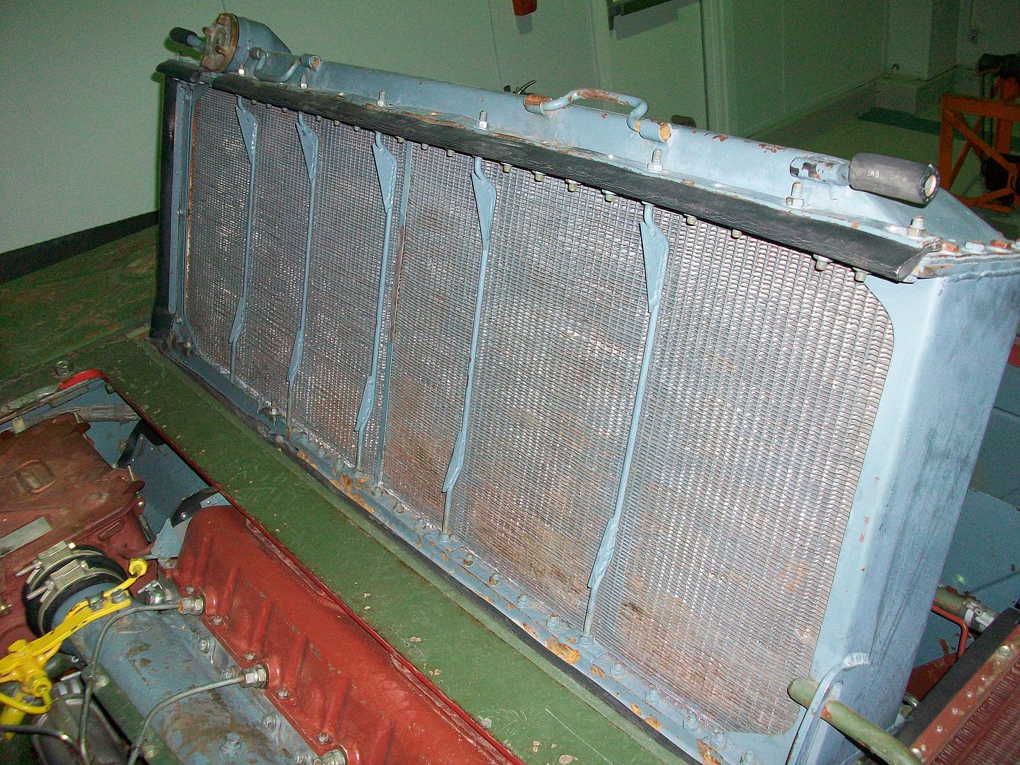
One minor disadvantage of the cooling system is that the ejected air is blown out of the centrifugal fan at a high velocity, so that the dust kicked up by the tracks gets sucked into the air stream. The effect is that there is a "rooster tail" of dust spouting from the back of the tank. This tends to be a problem in very dry and dusty conditions like in deserts or in some European summers but not in hot and humid conditions like in South East Asia (including Vietnam). If you happen to be a scout conducting forward observation in a very dry part of the world, faint "rooster tails" in the distance would be a dead giveaway that T-54 tanks are coming your way.
Swapping out the engine requires the armoured panel above it to be unbolted and shifted out of the way. Then, the engine must be decoupled from the transmission input shaft, and the four bolts that secure the engine crankcase to its mount on the floor of the engine compartment have to be removed. Then, all of the tubes and hoses including the fuel and water tubes have to be disconnected, and then finally, the engine can be lifted.
Many armour historians have observed that, among other things, one of the main factor behind the T-54's longevity is its automotive reliability and simplicity of maintenance. This is generally true. Quoting from Stefan Kotsch's website (link), which uses Russian sources including Uralvagonzavod's official works on the T-54:
"For example, in the period from October to November 1956, service station no. 20 was tasked to repair 188 tanks T-54. Of these, 18 had tanks, covered with the meantime the engine has change, a driving distance of around 8,000 km. Another 56 tanks reached an average of 6,031 km. The engines on 15 tanks achieved an average operating hours of 600 Mh, an even 696 Mh. Constructor Kartzev presented in 1956 found the tank T-54 can be used without major repair, for replacement of individual modules, certainly achieve a mileage of up to 10,000 km. Thus, the T-54 can be described as one of the most reliable tanks in the world."
According to Pat Ware and Brian Delf in "The Centurion Tank", the engine life of the Rolls-Royce Meteor was reported in service to be only around 3,000 miles (4,828 km) before a base overhaul was required. Many other tanks have been deemed "satisfactory" or "perfectly sound", but not many tanks have the same legendary reputation of toughness as the T-54.
WATER OBSTACLES

In 1958, the T-54 received the OPVT snorkeling system, thus gaining the ability to cross water obstacles as deep as 5 meters.

If the obstacle is too deep for unassisted fording but too shallow for the full snorkel tube to be used, a shorter snorkel section can be installed, as the photo below showcases.

When not in use, the OPVT snorkel is stowed away at the back of the tank, underneath the wooden log.
FUEL SYSTEM
T-54

The T-54 obr. 1947 featured four internal fuel tanks and three external fuel tanks on the fenders above the tracks. As shown in the drawing above (depicting the T-54 obr. 1951 fuel system)), the external fender fuel tanks were not connected with the fuel lines of the internal fuel tanks, but both the internal and external fuel tanks are connected to the engine through their separate pipes. This is designed so that the fuel supply to the engine can be switched between the internal fuel tanks, the external fuel tanks or switched off entirely, all done remotely from a rotary switch located in the driver's compartment.
The internal fuel tanks were located in the crew compartment. There were three interconnected tanks at the nose of the glacis, shown on the left below, and a single large tank in front of the bulkhead between the fighting compartment and the engine compartment, shown on the right below. These four internal fuel tanks had a total capacity of 520 liters, of which 300 liters is held in the two larger front hull fuel tanks in the nose of the glacis, 20 liters is held in the smaller tank between the ammunition racks and the wall of the hull side, and 200 liters was held in held in the rear fuel tank. The T-54 obr. 1951 featured an increased fuel capacity thanks to the addition of a 95-liter fuel tank on the right track fender. This arrangement was retained up to the T-54B model.


T-55

The T-55 modernization introduced new conformal fuel tanks that replaced the front hull ammunition racks in the tank. These new tanks held 300 liters of fuel. The rear hull fuel tank of earlier T-54 models was removed and replaced with ammunition racks. The loss of this rear hull fuel tank reduced the fuel capacity by 200 liters, but because the new conformal fuel tanks held 300 liters, a net increase of 100 liters was gained. An additional 280 liters of fuel was carried in the external fuel tanks located on the right track fender, like older T-54 models. Thanks to the additional fuel reserve, the driving range of the T-55 was expanded to 485-500 km on paved roads and 290-320 km when driving cross-country.


The T-54 had good fuel economy and a long driving range which was an advantage that was further accentuated by the T-55. Beginning with the T-54B, the driving range of the tank could be enhanced by two removable 200-liter fuel drums mounted at the rear of the tank. These fuel drums were not connected to the fuel network so the fuel must be siphoned into the fuel system manually, as was the case with the T-34. Doing so would require the tank unit to make a short halt which would delay the pace of the march, but not as much as completely stopping the unit and waiting for refueling trucks. Even so, this was recognized as a limitation and the T-72 was designed to have quick-detachable fuel drums that were connected to the fuel system.
In the absence of tank transporter lorries or appropriate rail transport, the T-54 could cover 500 km on a paved road under its own power. If the two external 200-liter fuel drums were fitted, the driving range of the T-54 and the T-55 on paved roads increased to 600 and 650-715 km respectively. Travelling across dirt roads and rough terrain will reduce the travelling range by almost half, as a rule of thumb.
The Centurion, in comparison, consumed fuel at an eye-watering rate of just 0.27 to 0.52 miles to the gallon, giving a range of just 33 to 62 miles. When Stalin closed down all avenues of entry to West Berlin in 1948 (nearly starting WWIII in the process), it became clear that Centurions would not be able to reach the city from their bases in West Germany without needing to refuel en route and waste precious time. This problem was only solved in 1963 with the installation of a bolt-on 109-gallon fuel tank at the rear of the tank, but the T-54 still maintained a huge - only now slightly smaller - advantage in road range and more importantly, fighting endurance.
DISTRIBUTION
It is impossible to discuss the T-54/55 without mentioning that it is the most widely produced tank design in the history of tanks. About 60,000 examples have been produced in the USSR alone, and tens of thousands more have been produced in satellite states. Copies and derivatives of the design, including the Chinese Type 59 and Type 69 boost the total number of tanks even further, making the T-54 the most produced tank in human history. The absurdly high production figures for the T-54 series gave the Soviet Army a decisive numerical superiority during the Cold War and ensured the longevity of the tank in the years to come. For comparison, Simon Dunstan stated that the production of the Centurion Mk. 3/5 medium tank ran from 1946 to 1958, during which 2,833 Mk. 3 tanks (1946-56) and 221 Mk. 5 tanks (1955-58) were manufactured. Three facilities were responsible for Centurion final assembly: Vickers Armstrong and the Royal Ordnance Factories at Leeds and Dalmuir. According to Spencer Tucker, a total of 4,423 Centurions of all types were built, of which 2,500 were exported.

Currently, the T-54 is in service in Russia as hard targets on firing ranges all over the country. A few examples are were serving in the Far East as coastal defence guns as recently as 2012, but since then, virtually all existing T-54 tanks have dismantled and melted down for their steel. Almost all of the examples that actively served in the Far East were leftover T-55A tanks equipped with KDT-1 laser rangefinders, but even these are now almost never seen outside of storage facilities.
