
The Soviet Union continued to develop and use anti-tank guns long after the concept was deemed obsolete and subsequently abandoned by other major military powers. This seems appropriate as the USSR was among the first to adopt this class of weapon, and their capabilities were greatly appreciated during the Spanish Civil War and in the Great Patriotic War.
The first Soviet towed anti-tank gun, the 37mm M1930, was a refinement of the 3.7cm Pak L/45 gun design carried out by the Rheinmetall company under a contract from the Soviet state as part of a large technological transfer programme that included the purchase of a dozen Pak L/45 guns. The technical documentation and the necessary machine tools to build the gun were transferred to the No. 8 factory, where the M1930 began to be mass-produced in 1931 under the factory index of 1-K. This was the first step taken to build up the technical expertise needed to form a domestic anti-tank artillery industry.
The original 3.7cm Pak L/45 was the latest and most advanced gun of its type, not only in Germany but also abroad. It was designed in total secrecy in Germany and began low-rate production in 1929, preceding both the French 25mm mle 1934 and the British 2-pdr. In its native country, it was not further developed until 1934 when political changes prompted the rearmament of Germany to further accelerate, but in the USSR, Soviet engineers began improving the M1930 gun as soon as mass production had been officially established. A new 45mm gun was designed on its basis by swapping out the barrel and modifying the breech assembly. The carriage was also improved. The upgraded product, bearing the factory index of 19-K, entered service in 1932 as the M1932. This was the first major divergence from the original 3.7cm Pak L/45 design, and with it, the USSR effectively leapfrogged the British and French in anti-tank artillery development - at least on paper.
The mass production of the gun proceeded badly due to a critical shortage of trained workers and the immaturity of the industry, which was further exacerbated by the intensely ideological nature of the state. After the situation was rectified in 1933, an effort was launched to upgrade the gun in 1934 by replacing the wooden carriage wheels with pneumatic ones and improving the traverse mechanism. These improvements culminated in the adoption of the M1937 gun, the definitive model which served in the Red Army at the outbreak of the so-called Great Patriotic War. Compared to the original 3.7cm gun, it was easier to mass-produce, had considerably better mobility, and its firepower was enhanced by its ability to fire much more powerful ammunition, both in terms of armour penetration power and in anti-personnel capabilities owing to its vastly more powerful fragmentation and canister rounds. It was, arguably, the best in its class in the world.
More importantly, however, the efforts leading to the creation of the M1937 catalyzed the rapid maturation of the anti-tank artillery industry. By the start of WWII, the industry was capable of designing original anti-tank artillery pieces from scratch that could rival the quality and capabilities of foreign designs, and organize the mass production of such guns in optimized assembly line factories that enabled huge quantities of high-quality guns to be built. The ZiS-2 is a prime example, being a completely original Soviet counterpart to the 5cm Pak 38 and 6-pdr guns from same time period.
It is perhaps worth noting that the development cycle of Soviet towed and self-propelled anti-tank guns, divisional guns and tank guns were usually created in separate parallel projects utilizing the same ammunition and sharing the same ballistics, and were often based on existing anti-aircraft or naval guns, as these roles required high ballistic performance. The two most notable examples are the 85mm and 100mm tank guns used in the later half of the Great Patriotic War. On April 15, 1943, the State Defense Committee issued a decree on strengthening the anti-tank defense of the ground forces, leading to an intense effort to place guns of increased power into service. The ballistics of the 85mm mod. 1939 (52-K) anti-aircraft gun were used as the basis for the 85mm D-5 gun borne out of this decree, which entered service very soon afterward in 1943 on tanks and self-propelled guns, but the order to develop a towed 85mm divisional field gun featuring the same ballistics was only issued in 1944 to replace the ZiS-3, later resulting in the D-44. The D-44 had nothing to do with the D-5, being a clean-sheet design, and the D-5 itself also shared nothing with the 52-K gun other than the cartridge and ballistics, having a completely new design and being assembled from proprietary parts This was essentially the same developmental trajectory as towed and self-propelled gun systems in the U.S, Britain and to some extent, Germany. This is exemplified by the towed 3-inch M5 and the self-propelled 3-inch M7 (on the M10) which were created from the ballistics of the M3 anti-aircraft gun, or the 8.8cm KwK 36 which was created from the ballistics of the FlaK 18 anti-aircraft gun.
Similarly, the 100mm D10 tank gun entered service in July 1944, followed by the 100mm BS-3 field gun a month later, and then the KS-19 anti-aircraft gun after the war. These three guns shared nothing in common other than the ballistics, which were inherited from the B-24BM (1939) 56-caliber 100mm naval gun.
In the aftermath of the Second World War, the appreciation of the value of anti-tank guns led to the continuation of anti-tank gun projects for both the ground forces and airborne forces. A myriad of systems were created, ranging from the basic towed variety to self-moving (SD-44) and self-propelled (ASU-57, SU-85) anti-tank guns. In this article, the following postwar artillery pieces will be examined in chronological order with a heavy emphasis on the context of their use:
- D-44 divisional gun (GAU index 52-P-367)
- D-48 anti-tank gun (GAU index 52-P-372)
- T-12 anti-tank gun (GRAU index 2A19)
- MT-12 anti-tank gun (GRAU index 2A29)
The 125mm Sprut-B gun entered service in the Soviet Army, but only in name. It was never procured in any meaningful numbers quantity and was never a serious part of the arsenal. As such, it is not covered in this article. Its self-propelled counterpart, the Sprut-SD, was somewhat more successful, but due to its self-propelled nature, it is also beyond the scope of this article.
INDEX
- Introduction
- Design Challenges
- Basic Organization
- Common Features
- Recoil Devices
- Carriages
- Protection
- Gunshield
- Direct Fire Protection
- D-44
- Deployment
- Mobility
- Carriage
- Protection
- Fire control
- Gun
- Ammunition
- D-48
- Deployment
- Mobility
- Carriage
- Protection
- Fire control
- Gun
- Ammunition
- T-12, MT-12
- Deployment
- Mobility
- Carriage
- Protection
- Fire control
- Gun
- Ammunition
INTRODUCTION
The GAU classification system for artillery pieces was fairly clear and straightforward, assigning a unique identity for each new design. Firstly, the designation of all artillery pieces would be given a "52" prefix, as Category 52 of the GAU index was reserved for artillery. This would be followed by a "P", denoting a gun. The following digits serve as both a categorization and identification number for the product, the first digit being an indicator of its class of caliber and the following digits being a major and minor number to indicate the firepower group and caliber group number of the cannon. According to the textbook "Индексация и маркировка боеприпасов артиллерии" (Indexation and marking of artillery ammunition), classes 1-7 for conventional guns represent the following calibers:
Class 1: 20-40mm caliberClass 2: 40-60mm caliberClass 3: 60-100mm caliberClass 4: 100-150mm caliberClass 5: 150-200mm caliberClass 6: 200-300mm caliberClass 7: 300mm caliber and above
Knowing this, the meaning of the 52-P-367 and 52-P-372 indexes can be deciphered easily. It is a gun in caliber class 3, firepower group 6, weapon number 7. For instance, the 52-P-367 (D-44) was preceded by the 52-P-366, which was the 85mm KS-1 anti-aircraft gun from 1944.
Artillery ammunition - denoted by the "53" prefix and an abbreviation of their type - built for the guns listed in this index were assigned the same categorization number. For example, the 53-BR-412 shell was named according to the index of the BS-3 field gun (52-P-412), the 53-BR-413D shell was named according to the index of the D54 tank gun (52-P-413), and the 53-BR-415 shell was named according to the index of the KS-19 anti-aircraft gun (52-P-415). All three were Class 4 guns, having a caliber of 100mm, were rifled, and had high ballistics. As such, they belonged to the same firepower group, and the different caliber group numbers serve to distinguish between different ammunition, ensuring that they are only used in the appropriate guns. Caliber group '0' for a projectile indicates that the projectile can be used with all guns of the same caliber.
In 1956, a new index was introduced to accommodate the ever-increasing quantity of new weapon systems, including rocket-based systems. The directorate itself was renamed from GAU to GRAU, with the 'R' standing for "Rocket". Unlike the old GAU index, the numbering system of the new index served only as an identification number and could not give away any useful details whatsoever on the nature of the weapon, thus better preserving secrecy. The T-12 anti-tank gun was named the 2A19 under this index, with "2A" denoting that it is a gun (or howitzer or fireworks launcher) and the number 19 simply identifying it as the 19th system to be indexed.
The artillery pieces discussed in this article can all be categorized as "quick-firing" guns, although this is an antiquated term that only remained in use almost exclusively in the British military and in its former colonies. This term was not used in the USSR, even in manuals printed for British anti-tank guns supplied through Lend-Lease. In "Handbook of artillery: including mobile, anti-aircraft and trench matériel", it is stated that the main distinguishing feature of a "quick-firing" gun is that its carriage is not shifted by recoil when firing. Instead, the gun recoils on the carriage and is automatically returned to battery by a recoil mechanism. Other features may contribute to the rate of fire of a gun, but do not constitute their identifying characteristics.
All of the guns examined in this article are field guns, with divisional and anti-tank guns belonging to subcategories of field artillery. According to the Soviet definition, the structure of a towed gun can be divided into three main parts: The gun tube, the recoil mechanism, and the carriage.
- The gun tube ("ствол") is the gun barrel together with a muzzle brake and the breech.
- The recoil mechanism includes the hydraulic buffer and hydropneumatic recuperator installed to the gun tube, forming the complete gun.
- The carriage consists of the suspension, the crossbeam serving as a chassis for the suspension, and the two carriage trails.
Anti-tank guns are a type of field gun but can be readily identified by being readily concealable and having high ballistic performance, typically superior to the field guns and howitzers.
When a rapid deployment in open terrain is necessary, the prime mover tows the gun to the chosen position and the crew disembarks to decouple the gun and set it up. The driver conceals the prime mover a short distance away, then joins the gun crew as an ammunition handler.
DESIGN CHALLENGES
Although an increase in firepower is always desirable, the successful use of towed anti-tank guns in battle was conditional on their concealability and their mobility. As the demands on the firepower of a gun increase, the task of balancing the design priorities becomes ever more challenging. Achieving a further increase in firepower with purely conventional means inevitably leads to a further increase in the size of the weapon. Generally speaking, the enormous weight of the anti-tank guns deemed powerful enough to deal with modern threats by the latter half of World War II drove the desire to mount guns onto low-cost vehicles to create self-propelled tank destroyers. However, with the exception of the U.S Army in 1944, tank destroyers never completely replaced towed guns for the major military powers, if not because of the advantages of towed guns, then simply because it was more expedient to build them in large numbers.
The USSR was somewhat unusual as they continued to pursue the development of new anti-tank guns throughout the Cold War. Although such guns proved to be the most effective anti-tank weapon on both the Western and Eastern fronts, the increased emphasis on mechanized warfare and the improved armour protection of late war tanks made it doubtful that anti-tank guns could remain small enough to be easily hidden - which was one of their primary advantages - yet powerful enough to handle the new generation of tanks.
As a rule, postwar Soviet anti-tank guns were exceedingly lightweight, but even so, the necessity of a large caliber to fight modern tanks left no allowances for lightening the weapon to the extent of matching the portability of the infantry crew-served guns like the 45mm M-42.
Initially, light towed anti-tank guns were proven and were still viable as wartime tanks were still far from being phased out. For this reason, the 57mm ZiS-2 continued production after the war until 1949, when production finally ended with 3,500 guns delivered from 1946 to 1949. Its continued production was necessary to fully displace all 45mm M-42 guns, which had fallen into total obsolescence by the end of the war and was being pulled from active units to enter long term storage or to be distributed to friendly states as military aid. A similar state of affairs transpired abroad, with equivalent guns such as the British 6-pdr continuing to serve in its original role until it was finally deemed obsolete and pulled out of service in July 1960.
Meanwhile, the hand grenades and PTRD rifles of the individual anti-tank soldier were replaced with the RKG-3 and RPG-2 respectively. All of these light weapons were only effective out to a range of several hundred meters, though not because of a decline in armour penetration power at long ranges as with a closed-breech gun, but because of a rapidly diminishing probability of hit. In any case, the effective range of the battalion-level weapons did not deteriorate.
Towed crew-served recoilless guns were widely adopted among the major military powers as a promising replacement for conventional towed anti-tank guns such as the ZiS-2, but they were not a panacea. In the Soviet Army, light anti-tank guns were pulled from high priority units throughout the 1950's beginning with the introduction of the SPG-82 in 1950. In 1954, the 82mm B-10 and 107mm B-11 recoilless guns entered service and took over the role of battalion and regimental-level anti-tank artillery respectively, then they were in turn replaced by the SPG-9 in 1962, which became the definitive weapon of its type for the remainder of the Cold War.
Even so, there was no recoilless weapon capable of the same ballistic characteristics of a towed gun, presumably because the backblast would be so immensely powerful that it would be impractical. In the USSR, the trend for recoilless guns was to reduce size and weight by reducing the caliver, increasing mobility, while also improving the firepower by using more sophisticated shaped charge technology and by implementing rocket assisted grenades. The Soviet Army did not pursue the creation of recoilless guns large and powerful enough to replace the likes of the D-48 or T-12, and quite rightly so. Rather, guided missiles were explored.
FOREIGN DEVELOPMENTS
Abroad, experimental anti-tank guns built to meet these conflicting requirements invariably ended in failure. At the end of WWII, both the U.S and Britain had ongoing projects to meet the requirement for high-powered towed guns, the U.S with their 90mm development programme, which evolved to create the 105mm T8 gun, and the British with their 94mm 32-pdr gun.
The only 90mm towed anti-tank gun to enter service and serial production in the U.S was the T8 gun, which entered service as the M26 gun on the M18 carriage. The gun was tall, but even worse was its enormous weight which reached an absurd level for a gun with only slightly greater muzzle energy than Soviet 85mm D-44 divisional gun and the German 8.8cm Flak guns. On page 41 of the book "US Anti-tank Artillery 1941–45" by Steven J. Zaloga, the weight of the 90mm gun when standardized as the M26 gun on the M18 carriage is reported to be 3,515 kg. The image below, taken from the book, shows the 90mm M26 gun. Its enormous weight may be related to its lack of a muzzle brake, a trait it shared with the 76.2mm M5 anti-tank gun which also had a preposterously high combat weight of 2,211 kg, far greater than the ballistically equivalent 75mm Pak 40 at a weight of just 1,425 kg.

Ultimately, this line of development was doomed by the fact that something with markedly greater firepower - and hence, even bulkier and heavier - was needed to deal with the new German Tiger II and Jagdtiger emerging in 1944. This task was to be handled by the even more powerful 105mm T8 gun, which was prototyped in 1944 and continued development until 1946, when, after tests in February of that year, the project was ended. The T8 weighed a whopping 8 tons, or around 7.2 metric tons.


The reticence to put new towed anti-tank guns into service was also strongly influenced by the high losses of towed guns in the ETO compared to self-propelled tank destroyers, which drove the replacement of all towed guns in tank destroyer battalions to self-propelled tank destroyers in 1945. Given that the technological limit of this class of weapon had been reached and no future prospects were identified, it is rather unsurprising that the War Department Equipment Board concluded in their study of towed anti-tank guns in May 1946 that "There should be no further development of towed anti-tank guns", thus effectively ending all development of this class of weapon in the U.S.
In the U.K, the difficulties in making the 17-pdr a viable weapon were already quite acute on their own. Developing a replacement that could handle future threats was a monumental task that proved to be insurmountable. The primary issue was the same that plagued the 17-pdr: mobility.
The first 150 examples of the 17-pdr were hybrids, consisting of the 17-pdr gun mounted onto the Mk. I carriage of the 25-pdr gun-howitzer. This model was known as the 17/25-pdr gun. It was an intermediate solution to deal with the problem of Tiger tanks in North Africa and brought a number of serious drawbacks. Firstly, though it was relatively light (2,097 kg) and could conduct all-round fire, the gun had practically no traverse arc if used without its rotary firing platform which required preparations to be deployed beforehand. It was also very tall, which was wholly undesirable for an anti-tank gun. As such, the definitive 17-pdr model, the Mk. I, was equipped with a conventional split-trail carriage. However, this gun was unreasonably heavy, having an in-action weight of 2,957 kg (6,520 lbs) or just under 3 tons. This made it extremely challenging for the 7-man crew to manhandle the gun even for short distances, except on paved surfaces.
The successor to the 17-pdr Mk. I was to be the 94mm 32-pdr gun. The first attempted solution was to convert the existing 3.7-inch AA gun by mounting it to a more suitable carriage, but the resulting gun and carriage were "monstrously large", as described by Chris Henry in "British Anti-Tank Artillery 1939-45". Two new proprietary carriages were designed for the new gun, complete with proprietary recoil systems and muzzle brakes, but the war ended before the project could be completed. In September 1945, the General Staff declared that there was no longer any requirement for the weapon, effectively ending the further development of not only the 32-pdr itself, but towed anti-tank guns as a whole.

As the project was never completed, there is no fixed data on the weight of the 32-pdr gun. However, Ian Hogg states in the book "Allied Artillery of World War Two" that the barrel alone would have weighed 2.5 tons, and that the towed equipment (the entire system) would have had a sensational weight of close to 10 tons, presumably short tons (9 metric tons), far surpassing the weight of even the largest 6-inch heavy guns. Naturally, this made it effectively impossible to move the 32-pdr without the use of a heavy prime mover such as the AEC Matador or Scammell Pioneer. In the photo below, the size of the 32-pdr next to the BL 5.5-inch medium gun (6.19 tons) lends credibility to Hogg's estimation of its 9-ton weight. If correct, Hogg's estimation of the system weight implies an extraordinarily inefficient design, bordering on sabotage. The design of the gun mount and shield in particular is highly suspect, inexplicably having a shape and size that is reminiscent of a naval gun turret. It is especially perplexing that so much trouble arose despite the 32-pdr being a smaller, less powerful gun compared to the Soviet 100mm BS-3 field gun.

Without a replacement, the 17-pdr continued serving through the Korean War era, predominantly organized under the Royal Artillery anti-tank regiments but also as individual batteries allocated to support an infantry battalion.
Though the intended successors to the 17-pdr and the M5 ended in failure, their obsolesence was still evident and the need for replacements remained. To fill this niche, large caliber crew-served recoilless rifles were developed to provide the necessary mobility for the guns to closely support small infantry units. In the U.S, the 105mm M27 recoilless gun entered service in 1952 to replace the 57mm M1 and 3-inch M5 guns under the Battalion Anti-Tank (BAT) weapon programme, followed by the 106mm M40 gun under the same programme in 1955. In Britain, the crew-served 120mm L1 BAT entered service in 1953 to replace the 17-pdr. Both developments shared the same design goals and were intended to fulfill the same tactical objectives.

Self-propelled tank destroyers were one alternative as they could serve as a convenient platform for large, powerful guns that would otherwise be impractical in towed form, but after the conclusion of the war, conventional tank destroyer concepts were no longer pursued by the U.S., U.K. and France. The need for a large gun to defeat enemy heavy tank was to be met by heavy tanks, or heavy gun tanks as they were known in the U.S. and U.K.. The American M103, British Conqueror were the products of this line of thought, and they would have been joined by the French AMX-50 if it were not for developmental difficulties. All three sported a high-power 120mm gun with a muzzle velocity in excess of 1,000 m/s, deemed necessary to ensure the defeat of the armour of the Soviet IS-3. In the context of such vigorous demands on firepower, the abandonment of not only towed anti-tank guns but also tank destroyers in favour of recoilless rifles seemed to be a purely pragmatic decision.
Large caliber recoilless rifles, firing large caliber HEAT or HESH ammunition, appeared to solve the problem of defeating the armour of heavy tanks, but they were far from a panacea. These weapons were only adequate for short range engagements given their low muzzle velocity, and the probability of kill against heavy tanks was not high even within their most effective firing range.
The table below, taken from "Ordnance Engineering Design Handbook - Artillery Ammunition Series - Section 2, Design for Terminal Effects" shows the probability of a firepower kill on a static IS-3 with a salvo of two shots from a 106mm M40 recoilless gun, using its integral spotting rifle to aim. As the table shows, even at a close range of 500 meters and with two aimed shots, a large caliber recoilless rifle had just a 1 in 3 chance of scoring a firepower kill. The maximum effective range of the weapon - where there would be at least a 50% probability of a firepower kill - would perhaps be only around 200-300 meters, contrary to its official maximum effective range being listed as 1,350 meters; that is merely the maximum direct fire range. If rated for a 55% probability of kill, as per the Soviet definition, the effective range may be no more than 200 meters.

To gain a better sense of perspective, the instruction for Red Army anti-tank artillerymen during the so-called Great Patriotic War was that guns were to open fire on tanks only from a distance of 600-700 meters while howitzers were to open fire from 400 meters. However, given that a heavy tank such as the IS-3 was practically immune to the Pak 43 and even the APDS ammunition of the 17-pdr at such short ranges, the shortcomings of recoilless guns do not seem debilitating.
BASIC ORGANIZATION
The basic structure of Soviet anti-tank artillery fire platoons, batteries, battalions, regiments and brigades was maintained throughout the entire Cold War. The largest unit of anti-tank artillery organic of a motorized infantry division was a battalion.
- A fire platoon consisted of 2 or 3 guns.
- A battery consisted of 2 or 3 fire platoons.
- A battalion consisted of 3 batteries.
- A regiment consisted of 3 battalions.
The smallest tactical unit was the fire platoon. Individual anti-tank guns were not to be used in isolation.
Outside of motor rifle divisions, a regiment of anti-tank guns was integrated at the army level. An anti-tank regiment could operate independently in the form of an army-level reserve defensive force, covering points of the front where there is a danger from tanks, or they can operate within the framework of a motor rifle infantry division, supporting it at such points as may be necessary, and also operating with the supporting tank group.
In a sector where there is a danger of a massed tank attack, the regiment can cover a large zone in both width and depth. The battalions would be arranged so that the batteries would be arranged in two echelons. Each battery forms an anti-tank strongpoint within the effective range of the other batteries, and would be positioned to permit mutual support. This creates overlapping fields of fire, and allows neighbouring anti-tank strongpoints to hit the side armour of the tanks if they launch a focused attack on the neighbouring batteries.
Soviet artillery divisions also featured a large contingent of anti-tank artillery. Each division would have an anti-tank brigade composed of four anti-tank battalions.
COMMON FEATURES
Some features of practically did not change throughout the evolution of anti-tank guns from the D-44 to the MT-12. These are the gun operating action, its balancing mechanism, its recoil management system, the carriage.
GUN
Unlike modern tank guns which have many built-in counterweights such as a powered elevation mechanism, armoured mantlet, and heavy recoil mechanisms to ensure a short recoil stroke within the confines of the turret, the design of a towed anti-tank gun had to prioritize reducing weight to the maximum extent possible. One example of this is the universal preference for implementing equilibrator mechanisms instead of adding steel ballast plates on the breech end to act as counterweights. Even the simplest and heaviest equilibrators could still offer significant weight savings, particularly for large high-powered field guns. Inside armoured vehicles, space is a more important consideration than weight, so ballast is preferred over equilibrators for balancing tank guns.
All Soviet towed guns had a vertically sliding breech. According to Soviet engineering manuals, if the bore axis of a tank cannon from the floor of the fighting compartment is lower than 950-1,000mm, a vertically sliding breech should be used, but if the bore axis is higher than that, a horizontally sliding breech should be used. This is because the convenience of ramming a shell through the breech changes depending on the height of the bore in relation to the height of the average loader (170cm). If the height of the bore axis is 950-1,000mm or less, the chamber will below the elbow of a standing man, so a vertically sliding breech is more convenient and it allows a long ramming staff to be used by someone standing behind the gun. This was particularly relevant for field guns given that such artillery often had to conduct indirect fire, as elevating the barrel would lower the breech even further.
Being direct fire weapons first and foremost, a large gun elevation arc was not the highest priority for anti-tank guns. The gun elevation limit is intrinsically limited by the bore axis height and the recoil stroke length of the gun. The lower the bore axis and the larger the recoil stroke, the less it will be able to elevate before striking the ground. If the design of the system creates a conflict between these two mutually exclusive specifications, then the elevation limit would always be sacrificed.
RECOIL MANAGEMENT
All Soviet anti-tank guns featured a muzzle brake as one of the principal recoil absorption mechanisms. In the textbook "Основи Будови Артилерійських Гармат Та Боєприпасiв" (The Basics of Artillery Guns and Ammunition) by A.Y. Derev'yanchuk, it is stated that during its recoil travel, the rearward momentum of the moving parts of the gun are absorbed by four primary mechanisms. As a rule, the distribution of braking forces across these four mechanisms are:
Friction: 3 - 5%Muzzle brake: 25 - 30%Recoil recuperator: 10 - 15%The recoil buffer: remainder
It is important to note that this is only a rough generalization. In the textbook "Курс Артиллерии - Книга 4" (Artillery Course - Book 4) from 1947, it is stated that muzzle brakes able to absorb up to 30-40% of the recoil energy are the most common.
As noted by Ian Hogg in the book "Allied Artillery of World War Two", anti-tank guns generally use a muzzle brake so as to save weight in the recoil system and carriage and yet still fire as heavy a charge as possible. The ZiS-3 serves as a good example of the utility of muzzle brakes, as it was ballistically identical to its predecessor, the 76.2mm F-22 USV field gun, but was 24% lighter thanks to a more efficient construction and the use of the lightweight carriage of the 57mm ZiS-2 gun. In turn, these changes were made possible partly due to the use of a double baffle muzzle brake which reduced the recoil force by 30%.
The most contentious feature of muzzle brakes is that the blast and gasses directed sideways cause dust and smoke to be raised across a very broad area across the front of the gun, rather than in a relatively restricted forward cone directly in front of the muzzle. Although it might not be immediately apparent, observation of the target becomes much easier as a result, because less dust and smoke is thrown forward of the muzzle and into the gun commander's line of sight to the target. In fact, a muzzle brake was often used to solve serious target obscuration issues, as was the case during the development of the American 90mm M3 tank gun, and it was the driving force behind the addition of a muzzle brake to the American 76mm M1 gun, leading to the M1A1C variant.
On the other hand, the dust and smoke cloud would be more noticeable to the enemy forces being fired upon owing to its great width, potentially provoking quicker return fire, and the visibility of the blasts to enemy air reconnaissance was also a source of consternation. The issue of muzzle blasts and smoke unmasking the position of guns was routinely expressed as a concern in Russian literature covering the development of artillery systems, while obscuration of the target was rarely ever mentioned in any evaluation of guns with muzzle brakes. In fact, the unmasking factor was sometimes cited as a major justification for the rejection of promising tank gun projects.
The drawbacks of muzzle brakes were essentially unavoidable for most of the towed artillery pieces created in the USSR as there were stringent weight requirements, but it was less of an dilemma for tanks, for which guns without muzzle brakes can be viable, though muzzle brakes would still occasionally find some application on light tanks to shorten the recoil stroke for internal space considerations. For towed anti-tank guns specifically, the tradeoff was always considered worthwhile.
RECOIL MECHANISM
Postwar Soviet anti-tank guns, including the three examples presented in this article, use a modified form of the Schneider independent recoil mechanism. Imperial Russia indirectly took part in the creation of this highly influential system by commissioning Schneider to design a howitzer to a set of specifications. The product of this work was the 152 mm howitzer M1910 howitzer, which served as the basis for many future artillery pieces. Moreover, the chosen caliber of 152mm (6 inches or 60 lines) was standardized in Imperial Russia and its legacy endures til this day.
As with any other hydraulic recoil buffer, braking is achieved by using a piston to drive the flow of oil through restricted openings so that a large hydraulic resistance impedes the flow, thus absorbing the energy from the recoil of the gun.
The entire volume of all three chambers in the buffer were filled with a fixed volume of oil. The flow of oil from the reservoir to the buffer chamber and the piston is regulated by the cross-sectional area of the ring-shaped restrictor bushing between the piston head and the spindle-shaped control rod. The spindle shape of the control rod generates a flow channel with a variable cross-sectional area as the buffer cylinder slides over the piston. The spindle maximizes the bushing area to generate minimum flow resistance during the firing of a shot, then progressively decreases the bushing area to steadily increase the flow resistance during recoil and decelerate the gun, bringing it to a gentle halt.
The drawing on the left below is of a hydraulic buffer, and the drawing on the right is of a recuperator. Both were taken from the textbook "Practical Supplement to the School of the Battery Commander" from the Saumur Artillery School, published in 1918 in English for American artillerymen.


The pistons of both the recuperator and buffer affixed to the immobile gun cradle, while their cylinders, containing large quantities of spindle oil or hydraulic fluid, were affixed to the recoiling gun assemblies. The replenisher tank for the recuperator also recoiled with the gun. This meant that the recoiling mass of the gun could be increased with no actual weight gain for the system as a whole.
Increasing the recoiling mass of a gun gives it more inertia, so that it is more inclined to remain motionless while the projectile travels down the bore. This can have a positive effect on shot dispersion to a limited extent. A heavier recoiling mass also possesses favourable recoil dynamics. Due to the conservation of momentum, the forward momentum of a fired projectile and its propellant gasses will impart a rearward momentum of the same magnitude to both a heavy and light gun, but during free recoil, the velocity of the heavy gun will be less. In turn, this reduces the kinetic energy of the moving gun (recoil energy), so that the buffer mechanism generates a smaller reaction force for a given recoil stroke distance, and due to the lower velocity, the braking time is larger which reduces the recoil impulse. In other words, the recoil of the weapon system as a whole is reduced.
The advantages of the Schneider system, as detailed in the textbook "Theory and Design of Recoil Systems and Gun Carriages" by the United States Army Ordnance Department, are as follows:
- An increased recoiling mass due to the recuperator sleigh containing the cylinders, recoiling with the gun and thereby decreasing the reaction on the carriage.
- The simplicity of the recoil mechanism, especially from a fabrication point of view.
The main disadvantage was that the recoil control was achieved with a spindle-shaped control rod of a fixed shape, and hence, shortening the recoil stroke for high angle firing was not possible. This could be a debilitating issue for howitzers, but not for field guns, and it was completely irrelevant for anti-tank guns.
A more serious downside was that the weight of the recoil mechanism shifted the center of gravity below the axis of the barrel, stressing the teeth of the elevating rack during recoil. This was easily solved by adding a clutch to the elevating mechanism that would be released by pulling the firing lever, so this layout was used on guns such as the A-19 field gun, ML-20 howitzer, the German Pak 36, IG 37, Pak 38 and Pak 40, just to name a few. On some cannons, this was solved by rearranging the buffer to be directly under the barrel and the recuperator cylinder above the barrel so that the center of gravity is aligned more closely with the bore axis. This layout was used on the ZiS-2, ZiS-3, the American 3-inch M5, and many other field guns and howitzers.

The summary of the Schneider system given in the "Theory and Design of Recoil Systems and Gun Carriages" textbook was particularly glowing:
On the whole the Schneider recoil system has proved one of the most satisfactory recoil systems used during the late war, being simple to fabricate and thoroughly rugged, due to its simplicity in design
Due to its compelling advantages, and the ease of bypassing or solving its drawbacks, the Schneider recoil system was copied and used in the vast majority of field guns created after WWI by not only the Americans, who were strongly influenced by French artillery practices, but also the Germans, and the Russians (Soviets) and various minor military powers, with the exception of the British.
CARRIAGE
A split trail carriage is a type of tripod carriage, as it has three points of contact with the ground. The two wheels constitute one point of contact, and the two trails are another two points of contact. A tripod is ideal for a firing platform because three points always define a plane, so it is inherently stable and a flat surface is not needed.
The length of the trails is determined by the power of the gun, the bore axis height from ground level, and the center of gravity of the weapon system. Because the bore axis is above the center of gravity, the recoil of the gun creates a rotational moment around the fixed anchor (spades), thereby causing the weapon to "jump" on its wheels. This issue is particularly problematic for anti-tank guns as they are powerful guns with strong recoil by nature, and direct fire at gun elevation angles of close to zero is the norm.
Firing at high elevation angles greatly reduces the rotational moment and thus bypasses the stability issue to a large extent, which is why howitzers can have short trails. For most artillery systems, firing at elevation angles close to zero is uncommon during combat, and as such, the carriages of such artillery systems would be optimized to provide maximum stability at elevation angles much greater than zero. In the textbook "Курс Артиллерии - Книга 4" (Artillery Course - Book 4) from 1947, it is stated that for an anti-tank gun, the minimum elevation angle at which it reaches maximum stability is 0-5 degrees, which is much more demanding than howitzers as they can afford to only reach maximum stability at a minimum angle of 12-15 degrees.
To enhance the stability of the system when firing at low or negative gun elevation angles, the distance between the three points of the carriage must be increased. This essentially means having longer trails, and the more powerful the gun, the longer the trails must be. This is undesirable as it adds weight and it increases the length of the weapon, increasing the turning radius of the prime mover and thus complicating maneuvers in built-up environments. A relatively common solution was to have detachable spades, but this only gave a marginal improvement and it also introduced its own share of complications. For these reasons, minimizing the bore axis height is strongly desirable in all field artillery, but particularly for anti-tank guns as it improves their concealability.
Relative to other forms of artillery carriages, the main disadvantage of a split-trail carriage is that it limits the horizontal firing angles to a forward arc, but the desire for all-round fire was nonsensical for anti-tank guns, and other types of carriages brought their own share of drawbacks.
For instance, the cruciform firing platform of the 8.8cm Pak 43 permitted all-round fire, but the suspension had to be dismounted for the gun to be deployed. The inability of deployed guns to instantaneously relocate meant that they were often left behind during a tactical retreat or lost to preventable causes. Similarly, a tripod firing platform as found on the D-30 howitzer could give an all-round firing capability and was stable at all firing angles, particularly when staked deeply to the ground, but it lost all mobility once it was deployed. Not only was it was totally impossible to rapidly uproot the gun once it was deployed, converting it to the transport configuration was also futile as the crew had no way of pushing the gun.
Conversely, a split-trail carriage permits a modicum of mobility at all times. There was also a great advantage in user friendliness when deploying the gun, as staking a tripod gun platform to the ground is slow and laborious on frozen ground. A gun with a split-trail carriage could dig its own spades into hard ground with the force of its recoil.
In general, the firing arc of a gun or a howitzer mounted on a split-trail carriage does not exceed the angle between the trails. The extremes of the arc are invariably reached just before the breech can be traversed directly over the right or left trail. If traversed above one of the trails, a typical gun would be blocked from elevating, or a vertically sliding breech block would not be able to drop down to open. Exceeding the angle between the split trails is to be avoided completely even if the pintle mount technically allows it, as the recoil would generate an abormal stress on the trails.

Unlike foreign carriage designs, the D-44, D-48 and MT-12 carriages had fixed ground spades on each trail, as opposed to the foldable or detacheable spades as found on guns like the Pak 43/41. The rationale is unclear, but it can be inferred that having carriage trails with a single-piece construction with spades permanently welded onto the structure is structurally stronger and more rigid than a comparable design with a hinged spade or removable spade of comparable weight, as there are no joints that require reinforcement.
Though a gun mounted on a split-trail carriage is able to fire without having been dug in beforehand, it is still always desireable to have the spades obstructed on an obstacle to prevent the gun from rolling backwards too far with every shot. The spades prevent the gun from displacing itself this way by digging themselves into the ground with the recoil of each shot. Furthermore, the stability of the gun can be enhanced by entrenching it. This is done by pushing the wheels into pits dug in the ground, then burying the spades and part of the trails into the ground. Chocks can also be placed behind the wheels. This virtually eliminates movement during recoil, and also lowers the profile of the gun. Hand spades are provided as part of the pioneering tool kit of each gun, and the chocks can be any debris found on the site.
As a rule, when preparing a temporary gun emplacement, the spades on each carriage trail should be dug-in before firing to ensure that the recoil of the first shot does not displace the gun rearward. When the crew needs to rapidly move the gun out of its firing position, they can push it forward a short distance to pull the spades out of the ground, join the carriage trails together and deploy the castor wheel, then pull the gun away.


A split-trail carriage does not allow rapid all-round fire, as the gun must first be uprooted and then rotated with great effort to fire outside of its initial arc. If a gun pit was dug with an opening for a predetermined firing arc, it becomes impossible to fire outside of that arc. That said, all-round fire is rarely useful for anti-tank guns, even in the event that they are overrun - in such a case, the outcome of the battle is already clear, and it can be expected that the crew abandons the gun. All-round fire is possible with some examples of field artillery, such as the 88mm 25-pdr divisional gun, 105mm L118 light gun and 122mm D-30 howitzer.
Part of the rationale for the all-round fire capability of the D-30 howitzer (besides lower response times for fire missions) was to ensure it could react instantaneously to the sudden appearance of enemy tanks from an unexpected direction, with the caveat that the gun is already deployed in the combat configuration; the D-30 did not allow emergency firing in the travel configuration. This capability may have occasionally been useful, based on the experiences of the Red Army during the Great Patriotic War in the event of an enemy breakthrough where the divisional artillery unit may not have realized that a breakthrough occurred, or the direction of the main thrust was unclear, or a smaller force broke off from the main thrust to attack the artillery unit. Given that anti-tank guns were a reserve force that would be deployed specifically to halt or delay a successful breakthrough, the ability to conduct all-round fire was totally unnecessary.
And so, with practically no contextually relevant downsides, the split-trail layout naturally became the de facto standard for anti-tank gun carriages among all military powers with an artillery design and manufacturing industry.
To increase the convenience of pushing the gun by hand, a castor wheel would be fitted. The first example of Soviet anti-tank artillery to have a castor wheel was the 100mm BS-3 obr. 1944 field gun, in the form of a separate module that could be fitted to the end of the spades, presumably by one man from the gun crew while the six other crew members hold the trails up.

All subsequent anti-tank guns, including all three guns discussed in this article, had a castor wheel integrated to the left carriage trail for ease of deployment and stowage when shifting the gun in and out of its combat configuration.
The castor wheel is needed on large and powerful guns, because the system is far too heavy for the crew to push or pull it on the ground by the carriage trails like a wheelbarrow. Given that the carriage has to be heavy enough to withstand the strong recoil of the gun, it naturally provides enough weight to counterbalance the gun for such an arrangement to work, ensuring that the castor wheel maintains contact with the ground and the gun does not tip forwards.
Once deployed, the castor wheel converts the carriage to a tricycle. The width of the wheel must be large enough to present a large contact surface, so that the carriage does not sink excessively in soft terrain. Also, the diameter of the wheel should be as large as possible so that less pushing effort is needed from the gun crew to surmount stones, branches or bumps in the terrain, and to reduce the likelihood of the wheel getting stuck in a rut.
Curiously enough, Soviet towed guns had an all-steel castor wheel, without even a rubber rim. Outside of the USSR, the U.S was the only nation to put an anti-tank gun with castor wheel into service; the 90mm M26 gun on M18 carriage. Like the other 90mm guns in development at the time, it featured a a pneumatic castor wheel, which would presumably offer better traction and some degree of damping compared to a steel wheel, but suffer from being susceptible to punctures from all manner of hazards.
The primary drawbacks of towed anti-tank guns include vulnerability to artillery and air bombardment, large manpower requirement to fully crew each gun together with their prime movers and ammunition supply trucks, inability to shift positions while under fire, and high vulnerability to direct hits. To survive contact with an attacking force, anti-tank units had to capitalize on their stealthiness to maintain the element of surprise. The primary survivability factors for a towed anti-tank gun and its crew were the effective use of camouflage, cover, concealment, secrecy and deception.
If the gun emplacement is discovered by enemy reconnaissance or by unmasking itself during combat, the gun crew has very little protection from artillery fire and air attack. Napalm in particular can be especially effective, as it is able to disable guns and neutralize their deeply entrenched gun crews by heat and asphyxiation, not to mention the morale effect.
In this regard, a towed gun has greatly reduced survivability compared to enclosed or even open-topped tank destroyers. However, a properly dug-in gun emplacement also includes trenches for the crew and dugouts for the ammunition stores, which effectively protects the weapon system from attacks of all types. In this context, the disadvantage of a towed gun is that such fortifications require hours if not days to set up, whereas a tank destroyer is innately protected by virtue of its armour plating. It is much more difficult to protect a gun from being disabled by artillery or air attack, as even when dug into a gun pit, the weapon is always still exposed above ground level.
If located by artillery observers, a battery of anti-tank guns could be quickly neutralized by enemy artillery, assuming that accurate fire is possible. The article "The interaction of artillery and heavy infantry weapons" published in the August 1941 issue of the Artilleristische Rundschau magazine gives the following guidelines for sudden fire to annihilate an enemy artillery battery, to be fired within 1 minute whenever possible:
- 72 rounds for each battery of light field howitzers (75mm)
- 60 rounds per 105mm cannon battery
- 48 rounds for each heavy battery of field howitzers (150mm)
Realistically, a more common form artillery fire would be neutralizing fire, which does not necessarily destroy the anti-tank battery, but forces the enemy into cover and temporarily prevents them from manning their weapons. In the same German artillery magazine article, it is stated that to neutralize a battery, the ammunition consumption will depend on the circumstances, but light field howitzers must use at least 120 rounds, and heavy field howitzers at least 80.
Unlike indirect fire artillery batteries that normally have to be set up on flat and open terrain, anti-tank guns were generally less susceptible to being seen by artillery reconnaissance prior to an engagement. This hardly changed throughout the Cold War, as advanced artillery reconnaissance technologies such as counterbattery radars were not applicable to direct fire weapons. Besides aerial reconnaissance, which still depended on manned aircraft, there were few other methods of detecting anti-tank gun positions.
With a dedicated armoured prime mover such as an AT-P or MT-LB, the possibility of fending off an infantry attack was somewhat enhanced owing to the fire support capabilities of the integrated machine gun. This decreases the likelihood of the gun being overrun or at least buys the crew enough time to evacuate from the position.
The main defences of a gun crew would be the terrain, field fortifications, their personal weapons (a Kalashnikov) and any other weapons organic to the battery. The only protection element integral to the gun itself is the gun shield.
GUN SHIELD
Written guidelines for the design of a gun shield are difficult to find. In general, it is a highly contextual matter, seeming to be an aspect of gun design that is left almost entirely to the discretion of the designer and the fancies of the testing commissions. Nevertheless, it is universally accepted that the purpose of a gun shield is to reduce the probability of a gun being taken out of action by enemy fire by protecting the gun crew, at least as far as the French, Americans, Germans, British and Germans were concerned.
A history and justification of early gun shields is provided in article "Shrapnel And Shields", published in the September-October 1906 issue of the Journal of the United States Artillery, Vol. 26 No. 2. The relevant passages from the article are as follows:
Till within quite recent years only two essential requirements were considered in the construction of field guns: power and mobility, While in time of war power was especially demanded, peace has always produced a marked tendency towards mobility. Now, to these two prime factors, power and mobility, a third condition has been added: protection. Up to this time protection has been considered not from thetechnical point of view of construction of material, but as dependent on the tactical employment of artillery (i. e. the disposition of guns behind cover). Therefore it did not receive attention in the designing of field guns.In great battles owing to the increased accuracy of infantry and artillery fire, it is often impossible to obtain sufficient cover by skilful disposition of batteries on the terrain, herce it has become necessary to adapt protection to the piece itself, that is to say, provide the shield. The artillery shield, which couldbe introduced only with the long recoil carriage, was thus a necessary consequence of the new system of artillery. The resulting increase of weight has not the same influence on the rapidity of fire as formerly, as the 5 cm. gun on long recoil carriage can not be fired appreciably faster than one of 7.5cm. of the same system.Attention had already been drawn to the direct protection of guns by means of armor on the carriages. In 1866 extensive tests were made at Mayence with an armored piece constructed by Schumann, the carriage of which was also designed by him. The adoption of axletree seats for field gun carriages might have suggested the idea of making the backs of these seats of sheet steel, thus providing a kind of shield for the cannoneers protecting them from infantry fire and shrapnel bullets. An invention of this nature was noted in the military press in 1892.From that time on, quite naturally, experiments were made in a systematic, continuous manner to determine the thickness, best metal, etc., for the shields, the necessity for which no longer admitted of any doubt. Likewise experiments were begun on the manufacture of projectiles for efficaciously combatting the shields.
The Soviet view point was largely the same, but authoritative military texts never fail to note the additional purpose of protecting the gun itself along with the crew. The textbook "Курс Артиллерии" (Artillery Course) published by the Voenizdat in 1943, devoted a footnote to explaining the purpose of a gun shield, stating that artillery shields are not only intended to protect personnel, but also to protect the gun system itself. It is further elaborated in the textbook "Курс Артиллерии - Книга 4" (Artillery Course - Book 4) that invulnerability of towed artillery from enemy fire is provided by the strength of the structure and shield enclosures that protect the gun crew and fragile parts of the gun from fragments and bullets. Much greater attention is paid to the importance of stealth and deception, noting that an important role is played by the camouflaging of the gun and the creation of shelters for the gun crew in the gun emplacement. In order to disguise the guns, they were made as low as possible and painted in a so-called "protective colour".
The lack of central direction in gun shield design is exemplified in the "Field Artillery Cannon Weapon Systems and Ammunition Handbook" by the U.S Army Field Artillery School, dated October 1981, where it is stated quite plainly that shields installed on (some) towed artillery weapons are constructed to protect the crew from fragmentation or small-arms fire from the front. However, the handbook gives no guidelines whatsoever to dictate their design, despite being the definitive engineering handbook on the topic. Because of this, there is little option other than to make inferences based on some observations. Although gun shields are ostensibly nothing more than simply sheets of steel fastened to the rotating gun mount, their design had their fair share of nuances to consider.
Firstly, it ought to be noted that the gunner's station on an artillery piece is invariably situated on the left, and the loader may either stand behind the gunner or stand to the right of the gun when loading it. Standing directly behind the gun while loading it was strictly prohibited for safety reasons and remains strictly prohibited on all artillery pieces.
The minimum height of the gun shield appears to be determined by the height of the gun breech when the gun is depressed to its maximum limit. If, by chance, the resultant shield meeting this requirement is not tall enough to cover the gunner while he is in a kneeling position, it seems that gun designers often take the liberty to extend it to ensure that the gunner has protection. This can be seen in the photo below of a Polish T-12 gun, which had been dug-in, making its small silhouette size even smaller. The gun shield is just barely tall enough that take cover behind it, the gunner has to be kneeling and hunched down.

The width of the gun shield is primarily dictated by the gun traverse arc and it cannot exceed the width over the tyres of the carriage, which often necessitates a sweep angle to ensure full coverage for the gun. As a side effect, fulfilling these criteria tends to ensure that the shield will also be wide enough to protect the gunner from the direct front. This is sufficient as long as the gun is pointed directly at the enemy, but no more. There are virtually no anti-tank guns that have a gun shield wide enough to protect the gunner from a shot coming from even a modest side angle.
The firing position for a gun is chosen so that its traverse arc can cover the entire width of the expected enemy front or at least the assigned firing sector for the individual gun. Logically, it follows that if the gun were to receive direct fire from the enemy, it would originate from within the same arc. If the gun is fired upon by an enemy located outside of its traverse arc, then the firing position was either overrun or was poorly chosen.
If the gun breech assembly is particularly long but the carriage is narrow, which is often the case for a high velocity large caliber gun, then the gun shield must be swept back to ensure that it provides protection across the entire gun traverse arc without exceeding the maximum permissible width.
If the gun breech assembly is particularly long but the carriage is narrow, which is often the case for a high velocity large caliber gun, then the gun shield must be swept back to ensure that it provides protection across the entire gun traverse arc without exceeding the maximum permissible width.
The 57mm M1 gun serves as a good illustration of this. It was unusual in having a particularly wide carriage which permitted a large traverse arc of 90 degrees, and to provide front protection when the gun was traversed to the extremes of this large arc, the gun was issued with a pair of additional fixed side shields which could be mounted on the carriage. Zaloga states in "U.S Anti-Tank Artillery 1941-1945" that in practice, these shields were rarely used, but nevertheless, the existence of these side shields demonstrates the connection between the gun traverse arc and the necessary shield width.

Shields also served a secondary purpose of improving crew working conditions by behaving as a blast shield. The drawings below, taken and adapted from the book "Engineering Design Handbook - Gun Series - Muzzle Devices" from the U.S Army Materiel Command, shows the reduction in overpressure afforded by a gun shield.

An anti-tank gun is reasonably well protected from the fragmentation of explosive shells when emplaced in a prepared position. Though the crew is exposed, this is largely irrelevant because the gunner is the only member of the gun crew whose duties involve him being obligated to be directly next to the gun when the gun is in action.
By design, all Soviet guns permit all available sighting systems to be installed simultaneously. This is particularly convenient for night fighting because the sight can be set up during the emplacement of the gun, before dusk, and then simply left in its mounting bracket until it is needed. The gunner can switch between any of the three sights at any time, and during night fighting, the gunner always has the option of switching back to the day sight in the event that the night sight malfunctions.

Based on the known penetration characteristics of 7.62x54mm LPS (light ball) bullets, a gun shield constructed from 4.5mm RHA steel should be capable of stopping 7.62mm light ball rounds at a distance of 100 meters. Protection from armour-piercing bullets is not provided. The 7.62x54mm B-32 (AP-I) bullet can perforate a 4.5mm RHA plate at 30 degrees from a distance of 700 to 800 meters, and a .30 caliber M2 AP bullet is capable of perforating 4.5mm of RHA at an impact velocity of 450 m/s, corresponding to a range of 800 meters. Above 700-800 meters, both rounds may be able to achieve partial perforation, so the shield still does not provide adequate protection.
According to the "Handbook on German Military Forces" written and published by the U.S War Department, the steel gun shield of the 3.7cm Pak 36 was sloped at 30 degrees and had a thickness of 3/16-inches, or around 4.76mm. In the U.S, the gun shields on all anti-tank guns had a standardized thickness of 6.35mm, regardless of the shape of the shield and its obliquity. According to Shirokorad, the 45mm M-42 anti-tank gun entered service in the Red Army in 1942 with a 7mm gun shield to provide better protection from armour piercing bullets. The weight of the gun shield increased from 53.7 kg to 79.5 kg.
The 5 cm Pak 38, which replaced the Pak 36, had a new gun shield consisting of two 4mm armour plates separated by a 1-inch air gap, sloped at 30 degrees. This spaced armour scheme was used for all future German anti-tank guns for the remainder of the war. Based on various studies on similar armour with small air gaps, the spaced gun shield of the Pak 38 and other guns provided a modest increase in mass efficiency compared to a single RHA plate, but ostensibly enough to have have been capable of stopping a 7.62mm armour-piercing bullet from 100 meters and above which would have been a notable improvement over a conventional 6.35mm or 7mm gun shield, achieved with only a small increase in weight.
In general, shell splinters are the main threat dictating the protection requirements of gun shields. Direct machine gun fire is not normally used to defeat an anti-tank gun, often because the guns are positioned in such a way that they are too difficult to be engaged with small arms fire. In the U.S Army field manual FM 14-12 "Tank Gunnery" from 1957, simulated anti-tank guns were to be engaged with HE shells from a range of 1,000-1,500 yards during qualifications tests.
The lack of a need for armour defeating capability from the coaxial .30 caliber machine guns on U.S tanks is reflected in the conspicuous lack of armour-piercing rounds in a typical ammunition mix. Throughout the Cold War, a mix of 4 ball rounds and 1 tracer round was the standard. Even if armour-piercing rounds were issued, their effective use is predicated on the tank closing in on the gun, which is not only extremely unwise, but more importantly, is against regulations.
According to the article "Development of Protection Technologies" published in the June 2009 issue of Defence Technology Review, ballistic casualties in general war, including World War II, Korea, Vietnam, Israel, and the Falklands were recorded as 59% from projectile fragments, only 19% from bullets, and 22% from other causes.
The table below, made by the WWII Armor historian group with data taken from TM 9-1907 "Ballistic Data, Performance of Ammunition" and organized into an easily readable format, shows the fragment density produced by a 90mm M71 HE shell, which is representative of the shells used by the 90mm guns of postwar U.S medium tanks. Compared to 75mm and 105mm HE, the fragmentation of M71 is low, but at least it has a slight advantage over 75mm HE in the greater density of fragments capable of perforating 1/4 inches of mild steel. Nevertheless, this is largely irrelevant because the gun shields of anti-tank guns constitute much tougher armour than 1/4 inches of mild steel.

High velocity direct fire guns are less effective against a small target with a low silhouette, such as entrenched anti-tank guns. This is due to the non-optimal fragmentation spray pattern for a HE-Frag shell with a flat trajectory, specifically the low fragment spray density forward and behind the burst. With regard to the American 90mm and British 20-pdr guns specifically, the difficulty in knocking out an anti-tank gun with their HE-Frag shells would have been amplified by a combination of a flat trajectory and poor bursting performance.


With the fuze in the superquick (Frag) or short delay (HE-Frag) modes, a direct hit on the gun shield from a large high velocity HE-Frag shell would also completely destroy the gun and can be expected to also neutralize at least some of the crew through the destruction of the shield itself. A direct hit with a HE-Frag round was responsible for the destruction of the MT-12 shown in the photo below. The gun shield was shattered by the explosion.

Canister ammunition such as the 90mm M336 round also cannot be expected to be effective because of the poor penetration power of the flechettes or pellets, which degrades even further when this ammunition is used outside of their maximum effective range of a few hundred meters (300-400 m) such that even relatively thin pine boards can stop the projectiles. For instance, the M336 round with its 2-gram pellets was only rated to produce one complete penetration per 6 square feet of a 1-inch thick pine board on a target 8 feet high and 90 feet wide at a range of 400 feet. At the same distance, a 7.62mm light ball round can be expected to perforate a stack of pine boards ten times thicker or more. With this limited performance in mind, it should be noted that the flechettes used in APERS munitions, which weigh just 0.5 grams each, have even worse armour penetration power.
With the sole exception of HE shells, all NATO tank gun ammunition was quite poor for the purpose of knocking out anti-tank guns. With the replacement of 90mm and 20-pdr guns by the 105mm L7 and the lack of a HE-Frag shell in its repertoire, the efficiency of NATO tanks against anti-tank guns declined sharply. The generalization that the ammunition available to NATO tanks had a very low efficiency against towed anti-tank guns is quite reasonable. Combat experience during WWII showed that firing explosive shells at the estimated positions of anti-tank guns was effective at suppressing the crew, but generally did not put the guns out of action.


After the so-called Great Patriotic War (GPW), divisional artillery continued to serve a secondary role as anti-tank artillery. Though the D-44 was a great improvement over the existing means of anti-tank defence in the Soviet Army, its capabilities against tanks were fundamentally outmoded. Such weapons would have been in great demand throughout the later half of the war, but by the end, it was recognized that 100mm guns were needed to combat existing heavy tanks and future threats. The development of towed 85mm anti-tank guns began in response to the appearance of the Tiger heavy tank and continued to be pursued after 85mm tank guns had successfully entered service for the IS-85, SU-85 and T-34-85, but none had passed trials by the end of the war. This was a somewhat unique situation compared to the prevailing trends. Anti-tank guns in use by the Germans, Americans and British were invariably first fielded as a towed version, which would inevitably be followed by mobility concerns, prompting the installation of the gun onto a vehicle mount.


A D-44 was provided with a fixed OP1-7 or OP2-7 telescopic sight for direct fire. The OP1 and OP2 series of sights were standardized sighting units with a replaceable glass pane for viewfinder markings. Both series began to be used only on postwar guns. The OP1-7 and OP2-7 models were a standard OP1 and OP2 sight with markings for the 85mm ammunition of the D-44. The OP2 was a later, improved model from the 1950's.


The OP2-7 sight has a slightly different construction. A pair of threads are stretched to form a crosshair in front of the lenses of the eyepiece group. This forms a crosshair in the viewfinder, serving as a reference point of the center of its optical axis.

Once the range is selected, all the gunner must do is elevate the gun until the center chevron is laid onto the target. If deflection has to be applied because of wind or to lead a moving target, the gunner uses the smaller markings on either side of the central chevron as aiming points.
S71-7

Another noteworthy feature is the wavy pattern of the top edge of the shield, commonly observed on Soviet guns. This served to break up the silhouette of the shield into an irregular shape, thus helping it blend in with nature, particularly if the gun was emplaced among rocks and mounds of dirt. This was an additional layer of built-in camouflage, in addition to the so-called "protective colour" of the paint on the gun. The camouflaging effect can be further enhanced by attaching foliage to the gun shield. Even a hasty effort can have a positive effect. The same concept of cutting the edges of gun shields into a rounded or wavy shape was also implemented on some French and British guns, but the vast majority of artillery, including domestic artillery, were built with simple straight-edged shields. Many had completely flat, rectangular shields that seemed to have been designed without any regard for concealability whatsoever.

The thickness of Soviet gun shields is standardized at 4.5mm. The grade of armour steel used for such shields is unknown. This detail was a holdover from the 37mm M1930 anti-tank gun, the first Soviet towed anti-tank gun. In general, this low thickness of armour stops only light ball rifle rounds and shell splinters. With only few exceptions, all Soviet towed anti-tank guns followed the standard set by the M1930 and retained the same 4.5mm thickness. This standard was not followed by other artillery pieces such as the 122mm M-30 howitzer, which reportedly had a 3.5mm shield according to "Энциклопедия Отечественной Артиллерии" (Encyclopedia of Domestic Artillery) by Russian historian A.V. Shirokorad and confirmed by a measurement on a real specimen.
DIRECT FIRE PROTECTION
Based on the known penetration characteristics of 7.62x54mm LPS (light ball) bullets, a gun shield constructed from 4.5mm RHA steel should be capable of stopping 7.62mm light ball rounds at a distance of 100 meters. Protection from armour-piercing bullets is not provided. The 7.62x54mm B-32 (AP-I) bullet can perforate a 4.5mm RHA plate at 30 degrees from a distance of 700 to 800 meters, and a .30 caliber M2 AP bullet is capable of perforating 4.5mm of RHA at an impact velocity of 450 m/s, corresponding to a range of 800 meters. Above 700-800 meters, both rounds may be able to achieve partial perforation, so the shield still does not provide adequate protection.
According to the "Handbook on German Military Forces" written and published by the U.S War Department, the steel gun shield of the 3.7cm Pak 36 was sloped at 30 degrees and had a thickness of 3/16-inches, or around 4.76mm. In the U.S, the gun shields on all anti-tank guns had a standardized thickness of 6.35mm, regardless of the shape of the shield and its obliquity. According to Shirokorad, the 45mm M-42 anti-tank gun entered service in the Red Army in 1942 with a 7mm gun shield to provide better protection from armour piercing bullets. The weight of the gun shield increased from 53.7 kg to 79.5 kg.
The 5 cm Pak 38, which replaced the Pak 36, had a new gun shield consisting of two 4mm armour plates separated by a 1-inch air gap, sloped at 30 degrees. This spaced armour scheme was used for all future German anti-tank guns for the remainder of the war. Based on various studies on similar armour with small air gaps, the spaced gun shield of the Pak 38 and other guns provided a modest increase in mass efficiency compared to a single RHA plate, but ostensibly enough to have have been capable of stopping a 7.62mm armour-piercing bullet from 100 meters and above which would have been a notable improvement over a conventional 6.35mm or 7mm gun shield, achieved with only a small increase in weight.
In general, shell splinters are the main threat dictating the protection requirements of gun shields. Direct machine gun fire is not normally used to defeat an anti-tank gun, often because the guns are positioned in such a way that they are too difficult to be engaged with small arms fire. In the U.S Army field manual FM 14-12 "Tank Gunnery" from 1957, simulated anti-tank guns were to be engaged with HE shells from a range of 1,000-1,500 yards during qualifications tests.
The lack of a need for armour defeating capability from the coaxial .30 caliber machine guns on U.S tanks is reflected in the conspicuous lack of armour-piercing rounds in a typical ammunition mix. Throughout the Cold War, a mix of 4 ball rounds and 1 tracer round was the standard. Even if armour-piercing rounds were issued, their effective use is predicated on the tank closing in on the gun, which is not only extremely unwise, but more importantly, is against regulations.
According to the article "Development of Protection Technologies" published in the June 2009 issue of Defence Technology Review, ballistic casualties in general war, including World War II, Korea, Vietnam, Israel, and the Falklands were recorded as 59% from projectile fragments, only 19% from bullets, and 22% from other causes.
Direct hits on the gun would be effective, but it is difficult to achieve direct hits on anti-tank guns because as a rule, they are very small, well-concealed and there is always extreme stress on the tank gunner from time pressure when attempting to return fire. Real experience showed that explosive rounds were always the first choice for dealing with anti-tank guns.
Information on the effect of the 75mm M48, 3" M42A1 and 76mm M42A1 is given in the report "Army Operational Research Group Memorandum No. 415", shared by the Tanks and AFV News website.
The table below, made by the WWII Armor historian group with data taken from TM 9-1907 "Ballistic Data, Performance of Ammunition" and organized into an easily readable format, shows the fragment density produced by a 90mm M71 HE shell, which is representative of the shells used by the 90mm guns of postwar U.S medium tanks. Compared to 75mm and 105mm HE, the fragmentation of M71 is low, but at least it has a slight advantage over 75mm HE in the greater density of fragments capable of perforating 1/4 inches of mild steel. Nevertheless, this is largely irrelevant because the gun shields of anti-tank guns constitute much tougher armour than 1/4 inches of mild steel.

High velocity direct fire guns are less effective against a small target with a low silhouette, such as entrenched anti-tank guns. This is due to the non-optimal fragmentation spray pattern for a HE-Frag shell with a flat trajectory, specifically the low fragment spray density forward and behind the burst. With regard to the American 90mm and British 20-pdr guns specifically, the difficulty in knocking out an anti-tank gun with their HE-Frag shells would have been amplified by a combination of a flat trajectory and poor bursting performance.

Interestingly enough, the survivability of Soviet anti-tank guns was indirectly enhanced by the proliferation of HESH shells among NATO armies as an alternative to HE shells.
According to the figures given in the memorandum "HEAT vs HESH Paper", studies done for the Trilateral Tank Main Armament Evaluation, held from December 1973 to August 1975, showed that the 105mm M393A2 HEP shell had a lethal area of 114 square meters against prone infantry, which is slightly inferior to a Soviet 85mm Frag shell (nominal kill zone of 130 sq.m). Also, HEAT shells were also much less effective owing to their small explosive charge and the non-optimal shape of the warhead. In terms of lethal area, HESH or HEP are considered approximately 40% superior to HEAT of the same caliber, implying that the lethal area of 105mm M456 would be approximately 70 square meters. Incidentally, it is reasonable to surmise that the fragmentation effect of a 90mm HEP shell would be approximately equivalent to this, which is to say that it is just as bad.

For comparison, the 100mm OF-412 HE-Frag shell has a nominal kill zone of 200 square meters and the 125mm 3OF19 and 122mm OF-471 HE-Frag shells have a nominal kill zone of 300 and 310 square meters respectively. In Soviet and Russian terminology, the nominal kill zone ("приведенной зоны поражения") of a shell is defined as the the area within which there is a 100% probability of a target being struck by one lethal fragment upon the detonation of the projectile. In this case, the target is considered to be infantrymen in the prone position. In principle, it is equivalent to the so-called "lethal area". In practice, the actual kill zone is much smaller because a "lethal" fragment is merely a fragment that contains enough kinetic energy to produce lethal injuries, but the actual likelihood of causing death is highly dependent on where the target is struck.
Moreover, a Soviet study on the firepower of Chieftain tanks was carried out using a captured Iranian Chieftain Mk. 5R with one of the topics being the fragmentation characteristics of 120mm L31A7 HESH shells when fired at soil with a simulated trajectory for an impact angle of 18 degrees, where it was found that the nominal kill zone was only 140 square meters. From this, it can be said that 120mm HESH shells have a fragmentation effect that is only approximately equivalent to a Soviet 85mm Frag shell under the same circumstances, with the 85mm shell impacting at an angle of no less than 20 degrees. The relatively flat trajectory of these shells is detrimental to their fragmentation effect, so in practice, the actual lethal area is smaller.

With the fuze set to the superquick mode, a HE-Frag shell can be fired at the canopy of trees near an anti-tank gun position with a certainty of detonating on contact with the leaves or the branches. This essentially produces an air burst effect which has a high probability of eliminating the entire gun crew and even possibly disabling the gun itself, preventing it from being brought back into action by nearby infantry. An anti-tank gun hidden at the edge of a forest or placed under a tree in the open can be quickly eliminated this way if it is detected. This is shown in the drawing below. It is worth noting that the scenario shown in the drawing is only for illustrative purposes, as field manuals strongly discourage the use of lone trees and clumps of bushes for concealment, as they stand out in open fields and are the first landmarks to be scrutinized by enemy tank crews.

It is important to note that HESH shells cannot be used this way due to their base fuze and the built-in fuzing delay, which is incompatible with the high-sensitivity instantaneous-detonation function required to work on tree canopies. Indeed, HE-Frag shells would be also ineffective for this purpose if the fuze were set to the "HE" mode. For a HESH shell to fuze properly, it would have to hit the tree trunk, but achieving such a hit could be harder than hitting the concealed gun itself.

It is important to note that HESH shells cannot be used this way due to their base fuze and the built-in fuzing delay, which is incompatible with the high-sensitivity instantaneous-detonation function required to work on tree canopies. Indeed, HE-Frag shells would be also ineffective for this purpose if the fuze were set to the "HE" mode. For a HESH shell to fuze properly, it would have to hit the tree trunk, but achieving such a hit could be harder than hitting the concealed gun itself.
If the trajectory of the HE-Frag shell is flat enough and the terrain permits, there is some chance of successfully performing a ricochet air burst when the fuze is set to the maximum delay mode. Alternatively, it is also feasible to depend on the flat trajectory of the shell by deliberately aiming at a point short of the gun and hope to defeat it by the mine action of a delayed fuze HE shell, and if the shell incidentally goes over the intended impact point, it would either land very close to the gun or strike the gun shield itself, which is also highly desirable. Interestingly enough, it was noted in the U.S Army technical manual TM 9-1907 that a HE-Frag shell with the fuze set to the delayed mode (HE) was especially effective against anti-tank guns because the shell could perforate the thin gun shield and then explode some distance behind the gun, killing all members of the gun crew instantly.

With the fuze in the superquick (Frag) or short delay (HE-Frag) modes, a direct hit on the gun shield from a large high velocity HE-Frag shell would also completely destroy the gun and can be expected to also neutralize at least some of the crew through the destruction of the shield itself. A direct hit with a HE-Frag round was responsible for the destruction of the MT-12 shown in the photo below. The gun shield was shattered by the explosion.

In general, airbursting ammunition would be the most effective against an anti-tank gun emplacement, but such ammunition would only be available to artillery. The closest approximation to an airbursting round for tank guns was APERS, which became available to tanks armed with 105mm guns in mass quantities as the M494 only in 1973. However, prior to this, the XM494E3 had been approved for low rate initial production in 1968 due to an urgent requirement issued by the Department of the Army, just in time for U.S forces in Vietnam to be issued small quantities of APERS rounds during the final years of the conflict. However, APERS did not produce the same target effect as airbursting HE-Frag shells, because it was designed to detonate in front of the target and it only disperses its flechettes in a narrow forward cone of 20 degrees. If adjusted to detonate above an anti-tank gun position, the built-in fuzing standoff of 75 meters combined with the narrow dispersion cone ensures that the flechettes would merely pass above the heads of the crew rather than spray fragments perpendicularly down onto the crew as an airbursting HE-Frag shell would. To achieve its anti-personnel effect, M494 must be detonated only as high above ground level as its natural trajectory in the direct fire mode would allow.
For this reason, the official description of the M494 conspicuously omits any mention of targeting infantry in covered positions, let alone entrenched infantry or fortifications. According to its description, the M494 round was designed for close-in defence against massed infantry assaults, for offensive fire against exposed enemy personnel, and secondary firepower capability is provided against lightly armoured vehicles and low-flying aircraft.
Canister ammunition such as the 90mm M336 round also cannot be expected to be effective because of the poor penetration power of the flechettes or pellets, which degrades even further when this ammunition is used outside of their maximum effective range of a few hundred meters (300-400 m) such that even relatively thin pine boards can stop the projectiles. For instance, the M336 round with its 2-gram pellets was only rated to produce one complete penetration per 6 square feet of a 1-inch thick pine board on a target 8 feet high and 90 feet wide at a range of 400 feet. At the same distance, a 7.62mm light ball round can be expected to perforate a stack of pine boards ten times thicker or more. With this limited performance in mind, it should be noted that the flechettes used in APERS munitions, which weigh just 0.5 grams each, have even worse armour penetration power.
Not only was the pellet density low even at such a short range, but the density of pellets with sufficient penetration power to perforate such a thin pine board is exceptionally small. Given these figures and the known dimensions of Soviet anti-tank guns, only 4-5 of such pellets can be expected to strike the gun, and their relatively thin gun shields can be expected to provide full protection even at near point blank range. At the short ranges where canister ammunition are normally used, it would be much easier to simply obtain a direct hit on the gun itself with a HE-Frag shell.
With the sole exception of HE shells, all NATO tank gun ammunition was quite poor for the purpose of knocking out anti-tank guns. With the replacement of 90mm and 20-pdr guns by the 105mm L7 and the lack of a HE-Frag shell in its repertoire, the efficiency of NATO tanks against anti-tank guns declined sharply. The generalization that the ammunition available to NATO tanks had a very low efficiency against towed anti-tank guns is quite reasonable. Combat experience during WWII showed that firing explosive shells at the estimated positions of anti-tank guns was effective at suppressing the crew, but generally did not put the guns out of action.

The 85mm divisional gun D-44 was designed at the OKB-9 design bureau of the No. 9 artillery factory, and produced at factory No. 9, as signified by the "D" index. In addition to improved anti-tank capabilities, better target effects on infantry and fortifications were also desired, as the firepower of the ZiS-3 was deemed unsatisfactory. The closest foreign counterpart of the D-44 was the British 25-pdr, which served as the standard British divisional gun from 1940 until 1967. The D-44 served in the Soviet Army under the same system of organization for divisional artillery as the Red Army during WW2. It was used in this role until the dissolution of the Soviet Union, although by that point, it could only be found in low-readiness units in Southern and Eastern Russia.
The ballistics of the existing 85mm 52-K anti-aircraft gun were used, but an entirely new weapon was created. In this regard, the creation of the D-44 did not follow the same developmental trajectory as the BS-3 field gun, which was designed around the barrel of the B-34 naval gun, or foreign examples like the American 3-inch M5 and the 90mm M26 guns, which were created by transplanting the 3-inch M1918 and 90mm M1 anti-aircraft barrels respectively onto new mounts.
The design documentation for the D-44 was sent from OKB-9 to the No. 92 factory named after Stalin, "Zavod imeni Stalina" (ZiS), where the first prototype was built. As the factory was named after Stalin, the gun received the name as an honorific prefix, making it the ZiS-D-44. After testing, the system was further modified at No. 9 factory. On May 8, 1945, the ZiS-D-44 gun was sent to the Gorokhovets training ground to establish its tactical-technical characteristics. The ZiS-D-44 failed these tests, one of the reasons being the unsatisfactory extraction of cases. It finally entered service in 1946 as the D-44, missing the war entirely. The adoption of the D-44 and its belatedness was in large part due to the novelties of the production technologies involved. The share of stamped and cast components by weight reached 41% compared to 25-30% in previous guns, and a whole host of new production processes were adopted at the plant to launch D-44 production.
Factory No. 9 was the only enterprise in the USSR that was engaged in the mass production of the gun, where a total of 10,918 guns were manufactured from 1946 to 1954. During the first year, 474 guns were produced. Although the total figure amounted to only around a tenth of the ZiS-3 production run, it was enough to rearm not only the Soviet Army but also its satellites. During its production run, the D-44 was exported to various Warsaw Pact nations in large quantities, such that the D-44 became a fairly ubiquitous weapon outside the Soviet Union by the late 1950's.
The D-44 would be replaced together with the old M-30 howitzer during the 1960's with the introduction of the D-30 howitzer, which served as a comprehensive upgrade to both artillery systems by combining the firepower of a 122mm howitzer with the range of the D-44, as well as by having an all-round fire capability. However, as with many weapon systems, the D-44 was never fully phased out in all motor rifle divisions. The 40th Army brought its D-44 guns into Afghanistan, where it proved to be inadequate as there was a strong demand for more powerful artillery capable of high-elevation fire as well as all-round fire to protect forward operating bases situated deep in the country. Because of these limitations, the D-44 guns of the 40th Army began to be replaced in 1981 by D-30 howitzers.
Outside of Afghanistan, it remained in relatively widespread service. It continued to serve in its role as divisional artillery after the dissolution of the Soviet Union, even taking part in the First Chechen War.


Soon after the D-44 entered service, it was recognized that VDV infantry had the same demands for firepower, but guns of such a weight were impractical without a prime mover. As such, the design bureau of factory No. 9 started work on motorizing the D-44 at the end of 1948. The project was officially approved on the 1st of January 1949, and work on creating a prototype began the same year. The first prototype was ready for factory and field tests in 1950, which continued until the system finally passed military trials in 1954. By decree No. 2329-1105 of the Council of Ministers issued on the 19th of November 1954, the SD-44 gun officially entered service.
In 1954, factory No. 9 converted 88 D-44 guns into the SD-44, and in 1955 another 250 were converted. In 1957, another 100 guns were converted and the production line reopened briefly to manufacture 109 new SD-44 guns together with 150 SD-44N guns with night sights. A total of 547 SD-44 guns were created.
By motorizing the gun, it could serve as its own prime mover and it could shift positions during combat more easily, in spite of the large increase in weight.
DEPLOYMENT
As a divisional gun, the D-44 took over the role of the ZiS-3. The term "divisional gun" refers to a specific category of field gun intended for divisional level artillery. It was recognized that divisional guns would also have to serve as anti-tank guns, and being a replacement for the ZiS-3, the D-44 was expected to fulfill this role as well. This meant that the D-44 was not only issued to the artillery regiment organic to the division, but also to the anti-tank artillery battalion in the division.
Among the other military powers, divisonal guns were not necessarily issued universally. Although the British Army used the 25-pdr and the Heer used various 75mm guns, in the U.S Army, 105mm howitzers had replaced 75mm field guns by WWII and continued to serve in lieu of field guns after the war.
A major aspect of divisional guns was their versatility. The effectiveness of 75mm field guns against tanks was demonstrated in WWI, and from then onward, the anti-tank capabilities of divisional guns became an important consideration. Versatility briefly overtook that of practicality during the early 1930's, when the idea of universal guns took hold due to the influence of Mikhail Tukhachevsky, who envisioned divisional artillery as having the versatility to fight all possible threats on a modern battlefield, including aircraft. As a result of this idea, the F-22 gun entered service in 1936. It was quickly replaced by the F-22 USV model lacking the anti-aircraft capability, and in turn, it was replaced by the ZiS-3 which was a classical 3-inch field gun, albeit one of an exceptionally modern design.
A common use for divisional or anti-tank guns, as practiced by all participants of WWII, was to attach the weapons to an infantry unit, and bring them up to provide support with direct fire against bunkers, field fortifications and machine gun nests. Whenever possible, tanks would be used instead, but as real experience showed, units were frequently below their theoretical strength and tanks were simply not available. The D-44 could be used for this purpose as well, but this practice largely died out with the conversion of infantry divisions to motorized infantry divisions in 1957.
After the so-called Great Patriotic War (GPW), divisional artillery continued to serve a secondary role as anti-tank artillery. Though the D-44 was a great improvement over the existing means of anti-tank defence in the Soviet Army, its capabilities against tanks were fundamentally outmoded. Such weapons would have been in great demand throughout the later half of the war, but by the end, it was recognized that 100mm guns were needed to combat existing heavy tanks and future threats. The development of towed 85mm anti-tank guns began in response to the appearance of the Tiger heavy tank and continued to be pursued after 85mm tank guns had successfully entered service for the IS-85, SU-85 and T-34-85, but none had passed trials by the end of the war. This was a somewhat unique situation compared to the prevailing trends. Anti-tank guns in use by the Germans, Americans and British were invariably first fielded as a towed version, which would inevitably be followed by mobility concerns, prompting the installation of the gun onto a vehicle mount.
Having the ability to engage from standoff distances was important. If combat took place at only a few hundred meters, the swiftness of the gun crew became paramount, as the enemy tanks were more likely to spot the position of a hidden gun and the effectiveness of their return fire was drastically increased. Dismounted infantry advancing ahead of the tanks could also spot and suppress the gun, or perhaps even overrun it.
As divisional artillery, the importance of the D-44 cannot be understated. It was issued to the 2 gun battalions of the artillery regiment organic to a rifle or motor rifle division. A gun battalion had 2 anti-tank artillery batteries, each consisting of 2 fire platoons with 3 divisional guns, for a total of 12 divisional guns in the battalion, and 24 divisional guns in the regiment. D-44 guns were also issued to the anti-tank battalion in each motor rifle or tank regiment. Overall, a motor rifle division was thoroughly saturated with D-44 guns. Alongside the gun battalions, an artillery regiment also had a howitzer battalion equipped with two batteries of 122mm M-30 howitzers for a total of 12 howitzers.

The D-44 was at the peak of its potency in the immediate aftermath of WWII up til the early 1950's, mainly because Western allies were still entirely reliant on wartime medium tanks of various models, much like the Soviet Army. Compared to the German heavy tanks of late 1944, the firepower needed to combat such tanks was far less demanding. Heavy tanks such as the Conqueror and M103 only entered service in 1955 and 1957 respectively, but ignoring the fact that they were only used in very limited numbers, they were not relevant targets for anti-tank artillery because their role was to provide long range firepower to a force of medium tanks from overwatch positions rather than being the proverbial tip of the spear in a breakthrough.
The British Army was mainly equipped with Cromwell and Comet tanks until the late 1950's, while the newly rehabilitated French Army, as well as the armies of other liberated European nations, had been supplied with Sherman tanks via various sources. By the outbreak of the Korean war, the U.S had ceased production of the M26 Pershing and low rate production of the M46 had only recently begun with a total of only 319 tanks completed. At the peak of its saturation during the war in Korea, the ratio of M26 Pershings to M4A3E8 Shermans present was just a little over 1:2. Outside of Korea, the proportion of Sherman tankss of various models was even larger, being the most numerous tank in use by the Western allies by a large margin. Needless to say, these circumstances were favourable for the D-44.
However, the situation did not last. Amidst the backdrop of a rapidly deteriorating relationship with the USSR, further worsened by the situation in Korean, the shortfall in modern tank production sparked the so-called "tank panic". Mass production of the M47 Patton began in 1951 as an interim solution to the lack of modern tanks while the output rate of Centurion tanks was accelerated to fulfill American orders. In fact, over half of all Centurions produced in Britain were purchased by the U.S under the MDAA for distribution among the NATO members in Europe. Though far from being frontally invulnerable to the D-44, these new tanks were nevertheless a troubling new threat. A little while later, the M48 entered service and began rapidly displacing obsolete tanks from the U.S Army tank fleet. Against such tanks, the usefulness of the D-44 was very limited.
Decades after their adoption, D-44 guns could still be used for training purposes, to keep reservists up to date on their skills, if nothing else. The photo below, from the livejournal user 477768, shows Hungarian artillerymen training with D-44 guns in around 1997-1998.

MOBILITY

The GAZ-63, the standard 4x4 utility truck of Soviet motor rifle infantry, was used as the prime mover of the D-44. Needless to say, the enormous number of guns meant that an equally sizeable fleet of trucks was needed to transport them, and for this reason, cheap, light utility trucks were ideal. The GAZ-63 was replaced by the GAZ-66 in the late 1960's. The D-44 shown being towed in the photo above has a GAZ-66 as its prime mover. A limber was created for the D-44 as part of its technical requirements for transportation by horses, but horse-drawn D-44s were not known to have been used in the Soviet Army.
The ability to be towed at high speeds by a mechanized prime mover was a basic requirement for the D-44 and for all modern artillery pieces of the mid-1940's, and to that end, it was equipped with fully rubberized tyres and a torsion bar suspension.
With its modern suspension and tyres, the D-44 was able to handle rough terrain about as well as any of its its prime mover could. It could reach a maximum speed of 60 km/h, effectively allowing it to be towed at a speed matching that of the trucks used to tow it. The top speed of the GAZ-63, for example, reached 65 km/h. On cobblestone roads and dirt roads, the towing speed can reach up to 35 km/h. Needless to say, the actual speed is highly dependent on the capabilities of the prime mover. Relative to wartime wheeled and tracked artillery prime movers, the prime movers in service with the Soviet Army had a larger load capacity and could thus negotiate rough terrain with more confidence.
When being towed in its transport configuration, the muzzle and the entire breech end of the weapon would be protected with a canvas wrap.
CARRIAGE

The crossbeam of the carriage is a cast steel girder, shown in the drawing above. It serves as the gun mount with a protruding pintle for gun traverse, while its hollow inner volume houses the torsion bars of the suspension. The crossbeam is the hub of the entire weapon, onto which the wheels, trails, and gun are fitted to form a complete weapon.
The swing arm on each wheel is a straight axle shaft connected to the end of their respective torsion bar. Gusmatic "GK" airless tyres with a sponge rubber core and the hub assembly from the GAZ-AA truck were used. The rim flange width and rim diameter were 6.5 inches and 20 inches respectively. Ordinary pneumatic tyres with the same specifications could also be mounted, but it was inadvisable as such tyres would suffer frequent punctures in combat conditions from not only fragments and bullets, but flying debris.
The tyres are worth mentioning, as the roadwheels of almost all German weapons such as the Pak 43 were merely steel wheels with solid rubber rims, while American and British artillery pieces were fitted with pneumatic tyres.
It is also worth noting that the D-44 did not have parking brakes for its wheels, which was fairly typical for a gun of its type as brakes are simply unnecessary, but may be unusual under American artillery practices. According to TM 9-3305 "Principles of Artillery Weapons", all towed artillery weapons have a parking brake engaged manually by their crews, while larger weapons like the 8-inch M1 and 240mm M1 have a service brake, normally a pneumatic type connected to the prime mover. For a D-44 or any other artillery piece with a split-trail carriage, splaying the trails apart would firmly root the gun to a spot, making manually-operated parking brakes totally redundant. The ommission of brakes probably helped saved some weight.

When the carriage trails are unlocked and spread apart, the torsion bar anchors for both carriage wheels are disengaged. This is done by having the trails push in a spring-loaded locking pin on their respective wheel swing arms when they are fully spread.

The locking pin connects the wheel swing arm with the carriage crossbeam, thus immobilizing it. The wheels remain free to rotate, so the gun can still be moved by its crew if necessary.

This feature enhanced the firing accuracy of a hastily emplaced gun by preventing the carriage from swaying and bouncing on its wheels after every shot, thus also suppressing the vibrations of the gun barrel. By extension, a higher firing rate could also be attained, as the gunner would be ready to fire follow-up shots sooner.
The long and slender trails of the carriage are of particular note, giving the overall system a total length of 8,340mm, which is over a meter longer than guns like the 3-inch M5 (7.1 m) and 17-pdr (7.35 m).

The weight of the carriage is just 972 kg. Of this, the suspension accounts for 222 kg of weight. This light proprietary carriage was made possible thanks to the high-efficiency muzzle brake used on the gun.
Like earlier domestic anti-tank gun carriage designs, the trails were cylindrical tubes rather than box girder sections. This was a design feature originally derived from the original 3.7cm Pak, which can also be seen in later German guns like the Pak 38 and Pak 40. The top and bottom part of the trails are additionally reinforced with quarter-diameter tube sections along a third of their initial length (at the end where they are fitted to the carriage crossbeam).

Compared to square tubes, the main advantage of cylindrical tubes is that they are simpler to produce. From an engineering standpoint, square tubes are more suitable as they provide a higher bending strength for the given application, but the tube can be weakened if the corners are welded or riveted, becoming more susceptible to buckling below the design load capacity. Being a single-piece component, cylindrical trails do not have this issue. The SD-44 uses the hollow internal volume of the trails as fuel containers to supplement the main fuel tank.

When set up in the travel configuration, the carriage trails are clamped together with a crossbar. The same crossbar also serves as the travel lock for the gun, featuring a hole which fits over a protruding lug on the breech housing of the gun to secure it firmly. This design, combining the travel lock with the trail clamp, was necessitated by the lack of recoil guide rails on the gun where the travel lock lugs would normally be placed to interface with the trails, as on the ZiS-2, ZiS-3, and BS-3.
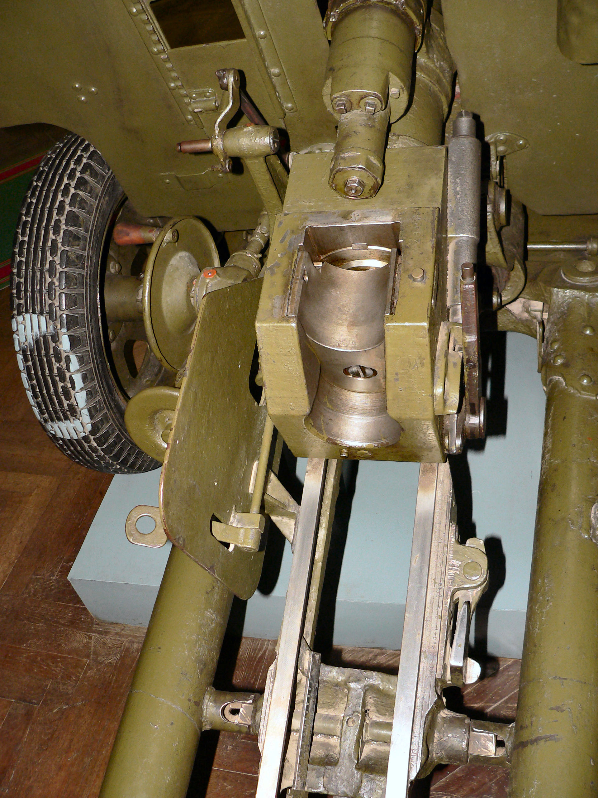
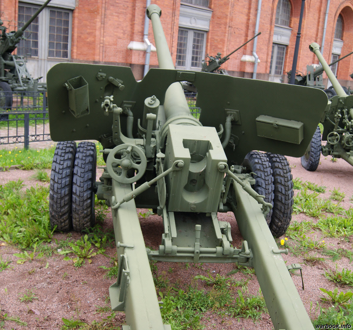

A castor wheel was fitted to the left carriage trail. It could swivel, enabling the crew to steer the gun when pushing it. If not deployed, it could be locked atop the gap between the trails for stowage when the gun is towed.

For the D-44, a castor wheel was not strictly necessary - a 6-man crew could cope with the weight of similar guns by handling it like a wheelbarrow. With a combat weight of 1,725 kg, the weight of the D-44 was 609 kg greater than a ZiS-3, making it over 50% heavier. However, the ZiS-3 was ballistically inferior and it was disproportionately light for its caliber, since it used the lightweight carriage of the ZiS-2. There was no direct equivalent to the D-44 in terms of design characteristics so it is rather difficult to find a fair point of comparison.
Compared to the 7.5cm Pak 40 anti-tank gun (1,425 kg) of a smaller caliber but more or less comparable ballistics, the increase in weight is far less pronounced. Older types like as the French 75mm Mle 1897/33 anti-tank gun, for example, weighed 1,500 kg. Another approximate point of reference is the British 25-pdr field gun, an 88mm weapon. Its ballistics were not equivalent to the D-44, having a muzzle velocity of just 532 m/s with a supercharged HE shell or a muzzle velocity of 610 m/s when firing its lighter 20-lb AP shot with the maximum overpressure charge. It did, however, have a weight of 1,633 kg, making it proportionately heavier.
In absolute terms, the weight and handiness of the D-44 was extraordinarily light for a gun of its power, considering its design features - it weighs less than half that of the 17-pdr Mk. 1, despite the fact that both guns had the same muzzle energy and both had high efficiency double baffle muzzle brakes. Generally speaking, its weight was roughly equal to pre-war 75mm field guns with poorer ballistics. According to the "Handbook of Artillery: Including Mobile, Antiaircraft, Motor Carriage, and Trench Materiel" prepared in July 1921 by the U.S Ordnance Department, it was considered that 3-inch field guns generally had a weight of about 3,900 pounds (1,769 kg). Such guns were deemed to provide the maximum firepower while remaining mobile enough to be practical for division-level operational maneuvers, hence their designation as divisional guns.
A short scene of a D-44 being pushed can be found in the 1984 Soviet film "Парад планет" (Parade of Planets).
PROTECTION

The primary protection factor of the D-44, as with any other anti-tank gun, was in its stealthiness, and in this respect, it is excellent. It is lower than the 7.5cm Pak 40 gun, which had a bore axis height of 960mm. The compactness of the gun, particularly the small size of its silhouette, is such that even a single row of sparse bushes is enough to completely conceal a gun emplacement.


Entrenching the gun is needed for maximum stability, and digging a gun pit was a prerequisite for a proper firing emplacement if the D-44 was used for indirect fire. Because of the limited gun elevation capability of the D-44, a recoil pit was not needed for it to fire at its maximum elevation angle, even when using a full charge. As with any other gun with a split-trail carriage, all-round fire is only possible with a delay, as the spades must be uprooted before the gun can be turned.
Ideally, when used as indirect fire artillery, the gun would be emplaced in a gun pit and covered with camouflage netting and foliage, as that provides the best protection from counterbattery fire and concealment from air reconnaissance. The raised earthen perimeter of the pit protects the crew from the fragments of shells landing outside the pit, and shells landing inside the pit will in turn have their fragments contained within, reducing damage to the surrounding personnel and equipment. Gun pits may also be dug on open ground for direct fire if the terrain does not allow hidden positions to be created.


Aside from its concealability and the protection offered by entrenchments, the gun shield on the D-44 provides some protection from bullets and shell splinters, though its small size, particularly its narrow width, means that it does not provide comprehensive cover.

The gun shield is supplemented with a hinged apron plate on the underside of the carriage crossbeam, made to cover the gap between the wheels so that shell fragments do not hit the feet of the crew members, assuming that the ground is uneven enough that there is no gap between the apron plate and the ground.

Above the gun, the gap in the gun embrasure is covered with a curved plate affixed to the gun cradle, but bizzarely enough, a gap in the embrasure is inexplicably present beneath the gun barrel. When the barrel is fully depressed, the height of the gap is insignificant, but it is greatly enlarged when the gun is elevated. The photo on the left below (courtesy of Andrey Alekseev) shows the rather large gap when the gun is elevated. The photo on the right below, taken from the kpopov website, shows the pneumatic equilibrator of the gun exposed through the gap in the shield.


When the gun is fully elevated, the gap in the embrasure can be up to 45cm tall. Its width is 26cm. Needless to say, such gaps are to be avoided to prevent shell fragments from damaging or jamming the moving parts of the gun. The incomplete cover around these areas is not uncommon among field artillery, but given the presence of an apron plate to cover the gap beneath the carriage, this omission is rather peculiar.


FIRE CONTROL
The only fire control instrument available was a rangefinder, issued at the battery level. Each gun battery was issued with a rangefinder which would be used to create range reference points, which would then be noted by the commanders of each individual gun. The rangefinder could also be used when coordinated fire at a single point target is needed. In the 1950's, the DS-1 or DS-2 stereoscopic rangefinders would be issued.
Meteorological data such as humidity, air temperature, etc, would be communicated to the battery from a higher level headquarters, which in turn would receive data from a meteorological survey platoon, an asset belonging to the artillery regiment of a motor rifle division. Regular updates in meteorological data are critical for long range indirect fire missions, but it matters less for direct fire purposes as the ballistic corrections are generally minor enough to be ignored.
SIGHTING
The D-44 is sighted with a simple telescopic sight for direct fire and a panoramic sight for both indirect and direct fire. The drawing on the left below shows the offset of these two sights from the axis of the gun barrel.

OP1-7, OP2-7


The OP1-7 had an increased fixed magnification of 3.5x and a field of view of 14 degrees. The relatively low magnification of 3.5x was not necessarily bad - considering its field of view, the optical design of the sight was excellent. For comparison, the No. 43 sight for the 17-pdr anti-tank gun had a slightly lower 3x magnification as well as a slightly smaller field of view of 13 degrees. However, the characteristics of the OP1-7 are somewhat odd considering that the M-42 45mm gun was equipped with the PP9-3 telescope with 5x magnification and a field of view of 8.5 degrees, despite being a smaller gun meant to engage tanks at short ranges.

The odd magnification of the OP1-7 was rectified by its replacement with the OP2-7. The OP2-7 had an increased fixed magnification of 5.5x and a field of view of 11 degrees. According to Soviet figures, an optical sight with 5x magnification allows an observer to see and identify a tank from a distance of 3.0 kilometers. For the purposes of the D-44, this magnification level was more than enough for any combat scenario, especially considering that a hidden anti-tank gun may sometimes be best utilized by delaying fire until the target is at a closer range.
In the 1956 book "Taktik im Russlandfeldzug. Erfahrungen und Folgerungen" by Eicke Middeldorf, republished in 2000 as "Русская кампания: тактика и вооружение", the assumption is made that in the terrain characteristic of the European theater, an anti-tank gun can fire at tanks on average at a distance of up to 500-700 meters.
The design of both the OP1 and OP2 sights is simple, but not crude. They provide a few additional features for ease of use in addition to the essential features of a functional gun sight. Unlike American direct fire sights for field artillery, the OP1 and OP2 permit the setting of the range with an adjustment knob, in addition to the calibration of the crosshair for boresighting. A removable rubber eye cup is provided on both sights to prevent extraneous light or rain from distracting the gunner's vision, while the OP2 also has a browpad for the gunner to ensure proper eye relief. Additionally, the OP2 was supplied with a high-contrast light filter that could be screwed to the end of the sight for better visibility in low light and when searching for targets against certain backdrops.

With the increased magnification and the introduction of a high-contrast filter, OP2-7 can be considered to be objectively superior to OP1-7 for combat in realistic conditions, where the lighting conditions can be far from ideal, and for long range gunnery.
For fighting at night, both sights have provisions for lighting the viewfinder markings using an externally mounted electric lighting system. The OP1-7 is illuminated with the "Luch-2M" system, whereas the OP2-7 is illuminated with the "Luch-S71" system. Light is provided by a small bulb fitted into a small window at the top of the sight casing.
In both the OP1 and OP2 sights, the viewfinder markings, including the range scales, are etched into a vertically sliding glass pane. To use range scales, the large range adjustment knob on the underside of the telescope tube is turned. An internal screw lowers the glass pane, thus lowering the sight markings in the viewfinder of the sight.
The OP1-7 sight has a single fixed horizontal thread installed in front of the lenses of the eyepiece group. When the viewfinder markings are adjusted vertically, the superelevation angle for range is selected by aligning the appropriate increment of the range scale with the horizontal thread.


The viewfinders of both the OP1-7 and OP2-7 were marked for reduced charge Frag, full charge Frag, and sharp-nosed AP shells (BR-365K). Evidently, the new 367 ammunition was yet not available at the time the sights were originally issued.
S71-7
PG-1

The S71 is a range setting device, designed for the adjustment of the gun in elevation, while the PG-1 panoramic sight is for laying the gun in azimuth. Both components are used together as a sighting system to enable the precise laying of the gun in both azimuth and elevation for indirect fire. Beginning in the last years of the GPW, all new field guns, including divisional and anti-tank guns, were fitted with the S71 mechanical sight as a standard feature. The S71-7 modification is simply an S71 sight calibrated for the D-44. The sighting system was designed for field guns, and as such, its elevation range is 0-750 mils, or 0-45 degrees. Howitzers, having an elevation limit greater than 45 degrees by definition, required a different sight.
The S71 is essentially a mechanical device designed to convert an input angle (in mils) into a superelevation angle that can be applied to the gun by elevating it. The S71 is rigidly mounted on the gun cradle so that its position shifts together with the gun. On the S71, the coarse adjustment drum is divided into increments of 100 mils per division. A full circle is divided into 6,000 mils under the Soviet definition, so there are 60 increments marked on the drum. The fine adjustment drum is divided into increments of 1 mil per division with 100 increments marked on the drum from 0 to 99. When the deflection of the sight is set to 30-00, the line of sight is parallel to the bore axis of the gun, and increasing the deflection angle above 30-00 offsets the sight counterclockwise whereas decreasing the deflection angle below 30-00 offsets the sight clockwise.
The PG-1 is a Hertz panoramic periscope, used primarily for indirect fire with the possibility of direct fire as an emergency backup to the direct fire sight. It serves as both a sighting optic and as a goniometer, with an azimuth scale marked on the rotating panoramic head for the gunner to measure the azimuth angle between two points in the distance with high precision. It is mounted onto a rotating bracket on the S71 sight, so that inputting an angle setting to the S71 rotates the PG-1 optic forward by the corresponding angle. When the gun is elevated, the PG-1 is returned to a level position.
The PG has a fixed magnification of 3.7x and a field of view of 10 degrees. It is tall enough that the gunner can look over his own head when the periscope head is rotated to look backwards. With these properties, the PG-1M provides a wider field of view than a telescopic sight, but proportionally, the field of view is smaller as the magnification is lower. If fixed facing forward, the sight can serve adequately as an alternative to the telescopic sight for direct fire or even as a supplementary sight for short range engagements.


The "Luch-S71M" illumination device was used to illuminate the reticle of the optical sight for more effective aiming during darkness. It runs on 3.5 V, 0.26-Amp power supply from an NK-13 battery.
Alternatively, a K-1 collimator unit may be used instead of the PG-1 in low visibility conditions such as at night or when distant landmarks are obscured with smoke, snow or heavy rain. The K-1 is a separate tripod-mounted unit, intended to be set up behind or to one side of a towed gun and within a certain distance from the PG-1. It is used by aligning an azimuth code in the viewfinder of the the PG-1 with the scale displayed on the K-1 display. The scale containing K-1 markings can be seen in the viewfinder of the PG-1 under the crosshair, as the drawing on the right above shows.


To use the optical-mechanical sighting system, the gunner uses aligns the reticle of the panoramic optic with the tip of a distant landmark. The landmark may be a radio mast, the tallest tree on a hill, a windmill or other similar structures. The battery headquarters, which is responsible for receiving fire missions and generating a ballistic solution for the entire battery, calculates and issues a certain deflection angle relative to the reference point.
The gun elevation angle would be set with an accuracy (maximum error) of 0.5 mils - a large improvement over older mechanical sights that permitted an accuracy of 2 mils.
NIGHT SIGHTS
1957 was a highly significant year for the ground forces as it marked the widespread introduction of night vision devices for artillery and armoured vehicles. Even the old ZiS-2 gun was modernized with a night sight, creating the ZiS-2N variant. Naturally, the D-44 could also be upgraded with a night sight of its own. Guns that were built or modernized with the necessary provisions for mounting a night sight were renamed as the D-44N, and the installation of a standard APN-3 sight converts it to the "N3" suffix.
For a weapon such as the D-44, a night sight was not strictly necessary, as a competently organized defence in depth would usually include a minefield at the very least, forcing an exploitation force to halt at a predetermined distance in front of the anti-tank gun emplacements, permitting pre-zeroed artillery to fire illumination shells over this zone while keeping the friendly gun emplacements in the dark.
Moreover, as towed guns are static, non-enclosed weapons that are practically silent (except for the brief moment a shot is fired), target acquisition under total darkness can be done by a combination of visual and audio means. One technique is to watch for the muzzle flash of an enemy tank to locate it, then count the number of seconds until the sound of the shot is heard to estimate the range. However, such techniques require the enemy to fire the first shot, which is undesirable, and rely on the assumption that the shot fired by the enemy was aimed somewhere else.
The tactical advantage brought by a night sight is that night fighting becomes much more feasible under non-ideal circumstances, which is likely to occur as the primary incentive of conducting offensives at night is to achieve surprise on the tactical level. If artificial illumination is provided intermittently during an engagement, the gunner of a D-44 may alternate between using the OP2-7 sight and his night sight.
Artillery night sights carry the "APN" designation, standing for "artillery night sight"; a simple naming convention, with tank night sights carrying the "TPN" designation, for example.
APN-2-7
Exists, but no information is available. Possibly experimental.
APN-3-7 "Yablonya"

The APN-3 is notable for being the first artillery night sight to be listed in the GRAU index - it has the GRAU designation of 1PN1. With the absence of information on the APN-2 series, the APN-3 series appears to have been the first of its type to be adopted by the Soviet Army, produced serially, and issued to the troops. The APN-3 would not only be the first artillery night sight, but also the only one of its type available for field guns meant for anti-tank work. The APN-3-5, APN-3-7, APN-3-55 and APN-3-77 variants were created for the BS-3, D-44N3, ZiS-2N and D-48 guns respectively.
The sight has a fixed magnification of 7.5x and a field of view of 6 degrees. The photo below, taken from the book "A Magyar Néphadsereg szárazföldi csapatainak hadrendi változásai 1987-ben", shows a D-44N operated by the Hungarian People's Army.

Pending further research, little can be said about this sight. It uses a single S-1 photocathode (as only Ag-O-Cs photocathodes were described in Soviet literature) and requires illumination from the enormous IR spotlight for effective shooting. In the technical manual for the sight, it is stated that the viewing range with infrared illumination is 800 meters, presumably facilitated by the high magnification of the sight and the much higher gain of a Gen 1 device, as opposed to a Gen 0 device such as the FG1250 of WWII vintage with a 400-meter viewing range.
The image below shows the viewfinder markings of an APN-3-7 for legacy ammunition. The reticle consists of a chevron with two vertical dashes for windage adjustments, and below the chevron is a vertical line and a horizontal line in an inverted "T" shape. The gunner adjusts the position of the reticle by turning a range dial to lower the reticle along the range scales until the horizontal line aligns with the desired range for the appropriate ammunition type. The range scale on the left is used for sharp-tipped AP shells (BR-365K), the center scale is used for full-charge Frag shells, and range scale on the right is for wartime APCR.

GUN

The D-44 fires the 85x629mm cartridge. According to A. V. Shirokorad in his encyclopedia "Энциклопедия Отечественной Артиллерии" (Encyclopedia of Domestic Artillery), the creation of the 85mm caliber was driven by the desire to optimize the performance of the existing 76.2mm M1931 anti-aircraft gun by using up the growth potential of its ammunition. The 85mm caliber allegedly emerged because it was the largest projectile diameter that could be fitted into a 76.2x558mm cartridge case, though contrary to this narrative, the resulting 85mm ammunition had a slightly longer and wider case to accommodate a larger weight of propellant, effectively making it an entirely new cartridge. Nevertheless, it shared the same operating pressure of the 76.2mm AA ammunition and had proportionally identical ballistics but weighed considerably more, and could therefore deliver a much larger payload to a higher effective ceiling.
Like the D-5 and ZiS-S-53 tank guns that came before it, the D-44 inherited the ballistics of the 52-K gun. Proportionately, the D-44 is ballistically equivalent to guns like the 7.5cm Pak 40, 3-inch M5 and 77mm HV. These guns fire AP shells with effectively the same muzzle velocity of 790 m/s or thereabouts. In terms of raw energy, the direct equivalent of the D-44 was the 17-pdr gun. The 17-pdr and D-44 were both L/55 guns and generated almost the same muzzle energy; firing an APBC round, the D-44 generates 2.988 MJ of kinetic energy at the muzzle, and the 17-pdr generates 2.985 MJ of energy when firing any of its standard 17-pound AP rounds.
It has a semi-automatic, vertically sliding breechblock, opened with a large lever on the right of the breech. The firing mechanism is completely mechanical, with a firing pin and striker. The breechblock-closing mechanism and the extractor are both spring-loaded, and are cocked by the recoil of the gun. The entire system is totally conventional, with no real differences from any other modern semi-automatic field gun of its time.


The action of the breech-opening mechanism is shown in the two drawings below, from recoil (left) to counter-recoil (right). Lever (19) opens the breech block.


The maximum rate of fire is 20 rounds per minute, but the aimed rate of fire is considered to be 10-15 rounds per minute. During tests of the ZiS-D-44 in 1945, the rate of fire that was achieved during indirect fire at an elevation angle of +20° with corrections was 15 rounds per minute. Without corrections, the rate of fire was up to 20-22 rounds per minute. The practical rate of fire, when considering the placement of the ammunition pit at a safe distance from the gun, is unknown.

As to be expected from a modern field gun, both the elevation and traverse controls on the D-44 are located on the left side, allowing a single gunner to lay the gun on target. By the time the D-44 was created, this had become a standard feature of artillery. Only legacy systems like the 122mm M-30 howitzer had separate gun laying controls for 2-man gun laying, with the traverse mechanism situated on the right of the gun cradle and the elevation mechanism on the left.


According to a technical manual for the D-44, it has a swinging mass (elevating mass) of 920 kg. This is defined as the weight of the gun assembly together with the gun cradle (99 kg) and control mechanisms (13 kg), as these comprise the elevating mass of the gun. The specified swinging mass includes the weight of a cartridge, as the gun is assumed to be loaded. Alone, the gun, consisting of the barrel and its breech, weighs 718 kg.
The mounting system permits the gun to be traversed by 27 degrees to each side, and the limits of gun depression and elevation are -7 degrees and +35 degrees respectively. It is worth noting that the maximum elevation angle is higher than any other anti-tank gun and it almost matches the ZiS-3 (37 degrees), which is appropriate given the importance of its role as indirect artillery. Because of this, the D-44 could fully exploit the increased energy of its full charge shells, allowing it to outrange the ZiS-3 by over two kilometers and thereby expand the flexibility of divisional artillery and even making it viable as a counterbattery weapon against the 105mm howitzers used by NATO forces.
The D-44 was equipped with a pneumatic equilibrator. It was of the push-type, with an oil seal, located to the right of the gun cradle. It consists of the main cylinder with the reservoir of the compensator next to it. The compensator is used to adjust the pressure in the main cylinder. The photo below, from an unknown source, shows a D-44 without its gun shield, revealing the equilibrator and the way it joints with the gun cradle.

The fact that the equilibrator is a push type indicates that the gun is breech-heavy, differing from the ZiS-3 which was muzzle-heavy. Generally speaking, a pneumatic equilibrator is an ideal type for a field gun and particularly for anti-tank guns, given that it has minimal weight and the relatively limited length of stroke is enough for the limited elevation arcs customary of this class of artillery.

The regulator piston had an oil seal which required 0.7 liters of oil, with part of the oil in the compensator. As the drawing on the right below shows, the oil seal is simply a loosely contained quantity of oil that rests between in the expansion chamber between the inner cylinder and outer cylinder. According to the technical manual for the D-44, when the equilibrator is operating at normal pressure (50-60 kgf/sq.cm or 4.9-5.9 MPa), the force on the elevation handwheel when raising and lowering the gun should be almost the same and should not exceed 7 kgf (68-69 N) in steady motion. When the ambient temperature changes, the pressure in the balancing mechanism is regulated with the compensator valve.


The recoling mass of the D-44, which is the weight of the barrel, muzzle brake, breech assembly and recoil mechanism, i.e all of the parts that move during recoil, weighs 785 kg. Compared to 85mm 52-K anti-aircraft gun with the same ballistics, large weight savings had been achieved. The 85mm AA gun obr. 1939 had a recoiling mass of 940 kg, while the D-5 gun used in the SU-85 (D-5S) and early T-34-85 tanks (D-5T) had a recoiling mass of 980 kg, or 25% heavier than the D-44.
The barrel is placed inside a cast steel cylindrical cradle. The forward half of the cradle serves to provide additional protection for the base of the barrel, where the projectile of a loaded cartridge rests.

During recoil, the gun is guided by bronze inserts attached to the walls of the cradle, ensuring that the barrel is axially centered during the initial recoil impulse, before and after the projectile has left the barrel. This provides greater axial stability than older artillery pieces relying on a single guide rail below the gun or symmetrical rails below and above the gun, and was not only used on all Soviet artillery pieces excluding 203mm artillery (B-4M howitzer, 2S7 "Pion"), but also on tank guns.

The total length of the gun, consisting of the barrel, breech assembly and muzzle brake, is 4,685mm or 55 calibers, the same as the 52-K anti-aircraft gun. This is rather short, considering the power of the gun. For reference, the KwK 36 gun had a much longer total length of 62 calibers, but fired its APCBC round at a slightly lower muzzle velocity of 773 m/s due to its lighter propellant charge. Alone, the barrel has a length of 4,146mm, making it an L/48.7 gun. The length of the rifled bore in the barrel is 3,496 mm, or just 41 calibers.

The chamber has a length of 650mm inclusive of the forcing cone, and it has a volume of 3.94 liters when measured up to the base of an O-365K shell loaded inside.
The normal peak pressure of the gun when firing a full charge round is 250 MPa (2,550 kgf/sq.cm), the same as the 76.2mm ammunition for the M1931 anti-aircraft gun. This pressure is reached with the standard AP, APCR and Frag rounds. HEAT and reduced charge Frag rounds produce a lower peak pressure.
RECOIL MECHANISM
The recoil mechanism of the D-44 uses the Schneider system, consisting of a hydropneumatic recoil recuperator paired with a recoil buffer. Unlike the original layout of the Schneider system, however, both recoil cylinders were relocated to above the gun. The cylinders of the buffer and recuperator were both affixed to the recoiling gun breech and the pistons were pinned to the gun cradle, to increase the recoiling mass, but there was no sleigh or guide rail. The omission of a heavy steel U-beam rail to guide the gun during recoil, as found on many guns including the 7.5cm Pak 40 and the domestic 100mm BS-3 field gun, gave additional weight savings.
A buffer-recuperator pair above the gun cradle reduces the barrel bore axis height and the distance between the bore axis to the recoil mechanism. By not having a large gap between the recoil mechanism and the barrel bore axis, the moment of force generated is minimized which diminishes the reaction forces from the cradle acting on the recoiling gun and also improves the stability of the gun.
The hydraulic buffer is shown as the top drawing below. It is filled with 4.75 liters of Steol-M. The hydropneumatic recuperator is shown below. It is filled with 3.4 liters of Steol-M, and is pressurized to 46.45 atm. The recuperator has a concentric compensator tank, simplifying the system compared to a conventional Schneider recuperator with separate, parallel tank.


An additional detail to note is that Steol-M itself is an anti-corrosion solution, but later guns had a chrome lining applied to the inner surface of the cylinder end cap to further increase corrosion resistance.
The normal recoil stroke length with a reduced charge round is 515-610 mm, increasing to 580-660 mm with a full charge round. The maximum recoil stroke is 675mm, marked on the indicator slide with the word "stop" to alert the crew that firing with the gun must be ceased immediately. If the recoil stroke of the gun does not reach the minimum threshold of 515mm, the automatic breech opening and ejection mechanism do not work, and the gun reverts to a quarter-automatic mode where the breech would have to be opened manually after each shot by one of the crewmen.
The D-44 uses the so-called "TsAKB type" double-baffle muzzle brake with flat baffles. It is recognizable for sharing the same shape as the ZiS-3 and D-25T muzzle brakes, developed by TsAKB. The brake is a one-piece steel casting. In general, muzzle brakes were cast from 35NGML or 30KhNML low-alloy steel grades, both ordinary grades that were commonly used for structural purposes.
A muzzle brake of this type was conventional at the time, and remains the most common type found on artillery systems even today. Most of the propellant gasses follow the exiting projectile through the hole in the first baffle, and the second baffle extracts some more work out of the gasses. Increasing the number of baffles beyond two brings rapidly diminishing returns, and hence, a double-baffle brake is universally considered to be the optimal design when muzzle weight is to be minimized for a given braking performance.
When a shot is fired, the propellant gasses exiting the muzzle expand into the free area outside the barrel, whereupon they collide with the baffles. The flowing gasses acting upon the surface area of the baffles generates a pressure by momentum transfer, which in turn creates a braking force, counteracting the recoil force experienced by the gun. Canting the baffles to redirect the gasses rearward can generate a further increase in braking force, at the expense of the working conditions of the gun crew.


As the muzzle brake still constricts the flow of the propellant gasses, though only to a limited extent, the pressure acting on the exiting projectile does not drop to nil within the length of the brake, so the projectile continues to accelerate. As such, a double baffle brake is responsible for a negligible increase in muzzle velocity. The gas pressure only drops completely after the end of the brake. This is shown in the graph below.

In terms of its effects on the mechanics of the gun recoil stroke, a muzzle brake can have a positive influence on the dispersion of shots. If the recoil devices are asymmetrically laid out, the asymmetric deflection of the barrel from its reaction forces can be limited by simply reducing the recoil force, thereby also reducing the reaction force. This reduces the "jump" of the gun after a shot and limits the barrel flex, which translates to less intense oscillations at the muzzle after a shot is fired. If the barrel has minimal movement during the next shot, there is less of an increase in dispersion if that shot is fired almost immediately following the first.
This is expressed in the "Engineering Design Handbook - Gun Series - Muzzle Devices" as follows
If, during the time the projectile is being propelled down the barrel, the barrel is in motion such that at the time of the shot ejection the muzzle axis has undergone some transverse or angular displacement from its undisturbed position or alternatively the muzzle possesses transverse or angular components of motion at the time of shot ejection, then the flight trajectory of the projectile will be directly affected.

The muzzle brake does not interfere with the flight of a full-bore projectile during and after its exit from the muzzle, and the TsAKB brake design was compatible with saboted and fin-stabilized projectiles as well.
AMMUNITION

For the first decade of its service, the D-44 was supplied with the same ammunition as that of the tanks and the self-propelled guns. This included the UBR-365K, UBR-365, and UO-365K rounds, all bearing the 365 series index as they were created according to the ballistics of the 85mm 52-K anti-aircraft gun which had a GAU index of 52-P-365.
85x629mm cartridges suitable for shooting from the D-44 could also be used without restrictions with 85 mm tank and self-propelled guns of various types, as well as with the 85 mm anti-aircraft gun mod. 1939 (52-K). Some projectiles of the 365th and 367th families were allowed to fire from an 85-mm anti-aircraft gun mod. 1944 (KS-1), but only with a propellant charge specific to this system in the sleeve (i.e., shots completed for the D-44 could not be used for this purpose).
Ammunition produced during the GPW was marked with "85-39" or just a plain "85" on the cartridge case, indicating an 85mm cartridge with the ballistics of the M1939 anti-aircraft gun. Ammunition produced either during or after 1946 was given an additional "85-Д44" marking together with a "85-СУ и ТАНК" marking. This may serve as a useful method of identifying wartime and postwar ammunition.
In the years following the war, a range of new ammunition developed on the basis of German types led to the introduction of an APCBC round and a new APCR round in 1956 alongside domestically designed smoke and Frag rounds. Instead of the wartime 365-series index, the new ammunition was given the 367 index. The internal ballistics of the new ammunition did not differ from the old series, so the D-44 could use existing stockpiles of ammunition and the new 367 series could be used in guns produced during wartime.
To further enhance the anti-tank firepower of the D-44, the first generation of Soviet non-rotating, fin-stabilized HEAT ammunition in the 85mm caliber (UBK-367) entered service along with a 76.2mm counterpart (UBK-354) for the ZiS-3. This ammunition was also compatible with the other 85mm guns in use after the war.
Aside from these types, the D-44 could also fire the 53-UD-367 smoke and 3UD1 illumination rounds, each with their own reduced charge variant.
The KV-4 percussion primer was used with all ammunition. According to the article "85-мм дивизионная пушка Д-44: Начало золотого века советской артиллерии" (85-mm divisional gun D-44: The beginning of the golden age of Soviet artillery) published in the February 2019 edition of the "Техника и вооружение" magazine, the KV-4 primer was rated for a peak pressure of 3,100 kgf/sq.cm, or 304 MPa. This allowed it to function without blowing out if the D-44 was fired with a full charge round at the maximum rated operating temperature of +50°C.
Frag
The focus on Frag shells and the lack of HE-Frag ammunition was a matter of expedience, as the cartridge was adapted from the 52-K anti-aircraft gun. For the anti-aircraft role where airbursting shells were needed to damage high-altitude aircraft, good fragmentation potential was greatly preferred over having a larger explosive mass. Originally, only the conventional steel O-365K shell was available. In 1956, the new O-367A Frag round with a cast iron casing entered service, enhancing the capabilities of the D-44 considerably.
With that said, it is worth noting that airburst shelling was not possible with the D-44 as no time-fuzed ammunition was included in its repertoire. The existing O-365 shell for the 52-K anti-aircraft gun, fitted with the T-5 pyrotechnic time fuze, was not authorized for use from a D-44, though it was cleared for use from tank guns during the GPW.
Purely high explosive (HE) shells were not used in the artillery of the Soviet Army for calibers under 152mm, because regardless of the efficiency of the shell design, a smaller caliber is simply physically incapable of containing enough explosive mass to destroy well-fortified shelters. For small caliber field guns such as the D-44, the use of Frag shells was quite normal.
53-UO-365K, 53-UO-367
53-O-365K

The UO-365K was one of the two main variations of contact-fuzed 85mm Frag ammunition that was issued as standard for D-44 guns. Compared to the O-365 shell, O-365K was slightly heavier and was fitted with a KTM-1 point-detonating impact fuze or a variant thereof. If the original KTM-1 fuze was replaced with the newer V-429 fuze, an additional "V" suffix would be added to the cartridge designation, becoming the UO-365KV. In addition to the basic UO-365K round, there was also the UO-365KZh which had the iron driving bands replaced with iron-ceramic bands, used during the Great Patriotic War. Compared to shells with conventional copper bands, these bands would erode the barrel bore at a 30% higher rate, but could increase the muzzle velocity very slightly and more importantly, were a viable alternative to circumvent copper shortages. For all variations of the cartridge, the case and explosive filler remained the same.
The TNT explosive filler weighs 741 grams. With an overall projectile weight of 9.2 kg, this gives an explosive filler weight proportion of 7.8%. This is firmly within the 5-10% range that defines a fragmentation shell. With this filler weight, the O-365K shell was proportionately equivalent to the 25-pdr Mk. 1D shell, as that had a 7.2% filler weight. The shell casing thickness is 0.21 calibers, which is typical of a fragmentation shell and is at the upper end of the 0.16-0.25 caliber thickness range specified in Russian artillery shell design textbooks.
The muzzle velocity of 793 m/s was achieved with 2.48-2.6 kg of propellant, depending on the brand used. It was possible for a D-44 to reach as far as 15.8 km and deliver good obstacle destruction and even armour penetration performance with O-365K, but the flat trajectory resulting from this high muzzle velocity can degrade the fragmentation efficiency in direct fire and short range indirect fire. This was not necessarily a major issue for the tanks and tank destroyers which were the primary recipients of the UO-365K round during the Great Patriotic War, but for the D-44, a reduced charge variant of the cartridge was needed for plunging fire.
This took the form of the UO-367 round, which was fitted with the same O-365K shell but had a lighter propellant charge weighing 1.5 kg or 1.8 kg, depending on the specific brand of powder used. A cardboard tube between the propellant bag and the projectile ensures that the propellant is always in contact with the primer and the burn rate remains consistent.

The 367 index of the round together with the compatibility marking of 85-Д44 on the case indicates that it was created for the D-44 specifically. It was not issued to tanks or self-propelled artillery.
The steel projectile casing is made from S-60 structural carbon steel, a standard steel grade for this purpose with a carbon content of 0.60%, hence the -60 index. Although heat-treated S-60 steel can have a relatively high strength, artillery shell casings built using S-60 steel are not heat treated after forging. This greatly reduced the time and demands on skilled labour required in the manufacturing process, and the resultant low strength yields better fragmentation characteristics.

Rather than using high-tensile steel which is a class of low carbon alloy characterized by high strength and ductility, carbon steel is relatively weak and brittle, which is conducive for splinter formation. However, due to the low strength, a thicker casing is required to resist projectile breakup during launch, which means that filler weight of the shell must be diminished. As such, such steel is most practical for fragmentation shells, while high strength steels would be used more often for HE shells.
Though HE shells have a larger explosive charge than Frag shells and have a much more useful blast effect by definition, the good ratio of filler to casing weight does not necessarily translate to a more powerful fragmentation effect compared to Frag shells. This is because uing high strength steel for shell casings necessitates a more brisant explosive compound to overcome the aforementioned strength and rupture the casing. But even with more explosive energy, the inefficient splintering characteristics of high strength steel, with elongated grains causing long splinters to be formed, makes Frag shells built with brittle carbon steel the superior choice as far as fragmentation effect is concerned.
The tensile strength of S-60 steel is 23-30 kg.f/sq.mm, or 225-294 MPa. The mechanical properties would naturally vary within this range depending on the particular design of the shell and whether heat treatment was applied or not, with different wall thicknesses also having a significant effect. For the O-365K, specific details are not known, but the large thickness of the shell casing walls and the known fact that heat treatment was omitted strongly suggests a low steel strength. For comparison, British artillery shells normally had a casing made from 19-ton steel, referring to the tensile strength in tons per square inch (tsi). 19 tons is equal to 293.4 MPa. This figure is nominally the same as the upper limit of 294 MPa specified for S-60, but the practice of foregoing heat treatment after forging differentiates the O-365K (and other Soviet artillery shells) from other artillery or tank HE shells.
Given an impact angle of 20-40 degrees with the ground, an 85mm HE shell has a nominal lethal area of 280 square meters for personnel standing in the open, or 130 square meters for personnel lying prone in the open. For comparison, for an impact angle of 20-50 degrees, a 122mm or 130mm HE-Frag shell produces a nominal lethal area of 800 square meters for personnel standing in the open, and 310 square meters for personnel lying prone in the open. As such, the target effect of a D-44 was very limited compared to the M-30 howitzers used in a rifle division's howitzer battalion, alongside gun battalions armed with the D-44. As a Frag shell, the small filler weight of the O-365K shell makes it largely impotent against field fortifications. The O-365K shell will be much more effective for D-44 guns used in direct fire, where accurate hits on field fortifications are much more likely, but conversely, the small impact angle on the ground in direct fire worsens its fragmentation effect.
UO-365K (UO-367)
Muzzle Velocity: 793 m/s (655 m/s)
Maximum Range: 15,820 m (13,430 m)
Projectile Weight: 9.54 kg
Explosive charge weight: 0.741 kg
Projectile Overall Length: 400mm
Casing Wall Thickness: 0.21 calibers (17.85mm)
Direct fire at lightly armoured or unarmoured targets such as APCs and trucks is most convenient with the full charge UO-365K round, as its point blank range for a target with a height of 2 meters (representing an M113 APC) is 950 meters.
53-UO-367A
53-O-367

Introduced in 1956, the UO-367A cartridge has a reduced propellant charge and contains the O-367 cast iron fragmentation shell. It was ballistically matched to the reduced charge UO-367 shell. It was also issued for use in 85mm tank guns in use with the Soviet Army at the time, as indicated by the "85 Д-44, ТАНК, СУ" marking on the cartridge case. This is further corroborated by the sight markings of modernized T-34-85 tanks.
O-367 was a Frag shell just like O-365K, but owing to its cast iron casing, it possessed superior fragmentation characteristics at the expense of a small sacrifice in explosive filler weight. Additionally, a full charge variant of UO-367A was not feasible, as a cast iron casing was too fragile to survive a high velocity launch. The muzzle velocity of 655 m/s was similar to the 680 m/s velocity of 76mm O-350A cast iron shells for the ZiS-3, which could be fired with a full charge only because its gun had poorer ballistics.
With an explosive filler weight of 670 grams, the explosive weight proportion is just 7% and conversely, the proportion of casing mass is higher to provide a larger fragmentation mass. The projectile casing is made from gray cast iron with a carbon content ranging from 2.7% to 3.3%, with a slightly greater thickness of 0.22 calibers instead of 0.21 calibers for additional fragmentation.
To ensure sufficient strength to survive being launched at ordnance velocities, the cast iron was formulated to have a tensile strength in the range of 23-30 kg.f/sq.mm, or 225-294 MPa. However, unlike a forged steel casing, a cast iron casing is invariably more brittle. While the structure of forged steel consists of long, uniform and tightly packed grains, critical in ensuring ductility and strength, cast iron has loosely packed grains of an irregular cuboidal shape. Ideally, the lower strength ensuing from the grain structure of cast iron would be exploited for further improvements in fragmentation potential, but in practice, the material must still be strong enough to survive a high-velocity launch. For cast iron shells, the low ductility is responsible for the enhanced fragmentation behaviour.
The formation of elongated fragments (splinters) is undesirable as they are ballistically inefficient, decelerating rapidly in flight due to tumbling and a large projected area. The upside is that the wounds caused by tumbling splinters are very serious within the short effective range. This type of fragmentation is unavoidable with standard high-tensile steels, as the process of fragment formation is characterized by longitudinal fractures forming along the length of the shell, creating long strips of steel which then split into shorter fragments in the shape of splinters, hence the name. Around 80% of the casing mass is formed into splinters, which only contribute a small amount to the total fragmentation effect. Low-elongation fragments are responsible for most of the effect.
The two images below show the stark difference in fragmentation efficiency between a Soviet 82mm O-832 cast iron mortar bomb (left) and a Japanese 81mm Type 100 steel mortar bomb (right). Besides the obvious difference in fragment quantity, it can be seen that the cast iron fragments had irregular polygonal shapes with a roughly cubic form, while the steel fragments were generally elongated, the majority of them being splinters.


In Chapter 1 of the book "Wound Ballistics" by the Medical Department of the U.S Army, the effects of the Type 100 bomb obtained during testing in 1944 was disclosed. Each bomb yielded 542 to 696 fragments, with a mean total of 608.6 fragments per bomb. On the other hand, in the report "Review of Soviet Ordnance Metallurgy" by the Watertown Arsenal, it is stated that tests of the O-832 bomb found that over 10,000 fragments would be produced. Compared to an American steel 82mm M43A1 mortar bomb, the O-832 bomb would produce 9.1 times more hits and 8.1 times more perforations in 1" pine boards within a 40-feet radius. This was despite the M43A1 bomb having a larger share of filler weight.
The superb fragmentation effects of cast iron bomb and shell casings was noted in "Wound Ballistics" along with the apparently "crude" construction of the bombs.
Whether it was inadvertent or intentional is debatable, but, in Korea, the Communist use of cruder cast metals in mortar shells seemed greatly to increase the number of fragments per shell and the effectiveness of their antipersonnel mortar fire when compared to conventional steel-walled shells. Often, the number of fragments per shell was many times that described previously for Japanese and German rounds.
Such a comparison is not meant to be scientific or outright conclusive, it merely illustrates the efficiency of cast iron as a casing material in lieu of research material directly pertaining to cast iron artillery shells. No known data is available for the O-367 shell at present, but from the available information, it is reasonable to assume that it offered drastically better anti-personnel performance compared to the O-365K shell.
Muzzle Velocity: 655 m/s
Maximum Range: 13,430 m
Projectile Weight: 9.54 kg
Explosive charge weight: 0.670 kg
Projectile Overall Length: 400mm
Casing Wall Thickness: 0.22 calibers (18.71mm)
AP
Initially, the D-44 merely fired the same AP and APBC rounds used since the GPW. Though the guns were excellent, the ammunition was of an outdated design. In 1956, new armour-piercing ammunition became available along with the new cast-iron Frag rounds.
All 85mm AP shells were APHE, with base charges of varying weights. The base charge in shells produced before 1940 used TNT with an incendiary pellet, but with the invention of A-IX-2, it became the new standard explosive-incendiary compound for APHE and HE-I shells. For the D-44, it can be safely assumed that all ammunition used was loaded with A-IX-2.
An interesting feature of all 85mm AP rounds is the inclusion of a phlegmatizer liner fitted between the propellant stick bundle and the wall of the cartridge case. The liner is wax paper, impregnated with either paraffin or ceresin wax, based on a description given in the 1970 textbook book "Современная артиллерия" (Modern Artillery).
When fired, the propellant gasses vaporizes the phlegmatizer and carries its particles into the barrel where it solidifies as a deposit on the surface of the bore, in a process known as sublimation. The coating forms a protective layer between the bore surface and the hot gasses. Its main purpose is to insulate the bore surface, lowering the rate of heat transfer from the propellant gasses and thus reducing heat erosion. The wax coating deposited on the bore surface is easily scraped away by the driving band of the next shot fired from the gun, so fouling does not occur even with sustained firing. Because of this mechanism, phlegmatizing liners are sometimes referred to as coolant liners, most notably in technical documents from Picatinny Arsenal.
53-UBR-365K
53-BR-365K

Though the UBR-365K round was clearly anachronistic well before the time the D-44 entered service, being an uncapped AP shell, it was still considered the main armour-piercing round for early guns, as evidenced by the markings in the OP1-7 and OP2-7 sights, where the "AP" ("БР") scale was marked for sharp-headed shells ("ОСТР").
With 2.48-2.6 kg of propellant, depending on the brand used, the 9.2 kg projectile would be propelled to a muzzle velocity of 800 m/s. The lack of a ballistic cap greatly inhibited its long range performance as the shell decelerated at a markedly higher rate than BR-365, an APBC shell. Nevertheless, the trajectory of the shell was still flat enough that the point blank range was effectively the same as BR-365. Its point blank range on a target with a height of 2 meters, 2.7 meters and 3.0 meters is 900, 1,050 and 1,100 meters respectively. In the immediate postwar era where the most common threat tank would be a Sherman, a Centurion or a Patton model of some type, the point blank range against a 3-meter target was directly applicable.
The forged steel penetrator body was made of low alloy structural steels, with the possible grades varying from 50Kh, KhZNM, 35KhGS, 35KhGSA, and then hardened by heat treatment. 35KhGS was overwhelmingly the most common grade used for sharp-nosed ammunition. 35KhGSA is a variant of 35KhGS with a lower sulfur and phosphorus content.
The shape of the nose is described as a tangent ogive with a caliber radius of 1.45 in a Watertown Arsenal Laboratory report, but the Russian textbook "Устройство и действие боеприпасов артиллерии" states that its radius is 1.53. It is possible that more than one model of BR-365K was produced serially.
The base charge is of a modest volume, containing 48 grams of A-IX-2. The explosiveness of A-IX-2 is 1.86 times that of TNT, giving the base charge a potency equivalent to 89 grams of TNT, together with an additional incendiary effect.


Two annular grooves were cut around the circumference of the penetrator body just behind the nose. Upon impact with an oblique plate, the compression waves travelling obliquely down and across the nose of the shell towards the base stresses the entire body. With the localizer grooves, these stresses are concentrated in the grooves, so that upon impact, the inevitable breakup of the penetrator body by shearing is localized to the nose where the grooves are situated, shearing the penetrator along the grooves. The shearing metal compresses the projectile nose and converts the shear stress to a volumetric stress, so that the shear cracks do not spread to the rest of the body and thus reducing the likelihood of shell destruction. The base charge, which is a structural weakening element, remains intact thanks to the grooves, so that it can burst behind the armour plate.
Their function, as explained in various Soviet technical literature such as the 1970 textbook "Современная артиллерия" (Modern Artillery), was correctly deduced in Watertown Arsenal reports analyzing captured 76mm and 85mm ammunition.
Additionally, the localizer grooves ensure that the nose shears off when impacting sloped armour plate, rather than allowing the shell to simply dent the plate and ricochet off. This is more likely with BR-365K and other Soviet sharp-nosed shells than their foreign counterparts, as the metal of the shell is characterized by high toughness rather than high hardness.
According to the specifications, detailed in the textbook "Устройство и действие боеприпасов артиллерии", the core of the nose is hardened to a Brinell hardness indentation diameter of <2.9mm (at least 444 BHN) and the base and midsection of the body is hardened to 3.2-3.7mm (269-363 BHN), with the base being the softest. Rather than hardness, the grade of steel used and the heat treatment methods promote higher toughness, reducing the likelihood of failure by shatter. According to the specifications, the nose had to meet this minimum hardness specification, but the penetrator body just behind the nose, a critical zone that had to remain intact, had to reached a hardness of 50 HRC.
In the Watertown Arsenal Laboratory report "Metallurgical Examination of Soviet 45mm, 57mm, and 85mm APHE Projectiles FMAM 1121, 1935, and 2175", a metallurgical analysis of a captured BR-365K specimen found that the average Rockwell hardness is 47 HRC from the tip of the nose to the obturating band, and from there the hardness decreases rapidly to approximately 26 HRC at the base. The hardness decreases from surface to center from 50 HRC along the cylindrical surface to approximately 44 HRC in the center of the body. From this, it can be seen that this specimen fully met the specifications.


The steel was described in the report as being an Mn-Si-Cr steel with a medium carbon content, which matches the chemical composition of 35KhGS. It has 0.35% carbon and the main alloying elements are magnesium, silicon and chromium.
There are numerous indications that the metallurgical design of the shell, namely the choice of a structural steel, was focused on toughness. The grade itself was specified for applications requiring a toughness with high strength, and impact strength. The presence and proportion of each main alloying element had the following purposes:
Chromium: gives high strength and resistance to corrosionSilicon: increases the level of impact strengthManganese: increases resistance to mechanical stress
In the Watertown Arsenal Laboratory report, it was observed that the shell was only moderately hardened, and that a reduction in penetration power was to be expected. At the same time, further hardening may also be undesirable. As noted in the report, steels with a 0.32-0.38% carbon content harden to 52-55 HRC upon complete transformation to martensite. However, though hard, martensitic steel is also very brittle, which is an important detail left out in the report.
Additionally, it was noted that the base of the BR-365K shell was heat-treated to a low hardness but rather than gaining toughness, became embrittled. The ideal practice was described in the report was to fully harden the entire body into martensite, and then apply a differential temper to create a progressive softening and toughening towards the base, allowing the base of the projectile to survive the penetration process intact, and pass behind the target plate. However, the report does not correlate potential issues with the breakup of the base with the presence of the localizer grooves, the purpose of which was to isolate penetrator breakup to the nose region, which may make this type of differential tempering unnecessary for the base to survive intact after armour penetration. But with that said, this a matter that is strongly dependent on the target properties, the impact velocity, and impact angle, so generalizing the behaviour of the shell is difficult.
Contrary to the negative assessment given in the report and the remarks that the least desirable heat treatment method was applied to the base of the shell, the embrittlement of the shell base may have been completely deliberate. A brittle casing around the base charge promotes fragmentation, particularly fragmentation into a larger quantity of smaller splinters, to enhance the probability of striking multiple internal components in a tank. Toughening the shell walls surrounding the base charge would have the same negative effect on fragmentation as on HE or Frag shells.
According to the Watertown Arsenal Laboratory evaluation, the BR-365K shell was estimated to be effective against slightly undermatching armor up to 60-degree obliquity and against somewhat overmatching armor at 0-30 degrees of obliquity. Specifically, it was estimated that the shell would probably perform almost as well as the 90mm T33 sharp-nosed AP shot against 2 inches of armour sloped at 45-60 degrees and 3-4 inches of armour at 0-30 degrees of obliquity, but probably inferior against "more severe" targets, presumably referring to thicker plates sloped at a greater obliquity.
Muzzle Velocity: 800 m/s
Cartridge Mass: 16 kg
Projectile Weight: 9.2 kg
Explosive Charge Weight: 0.048 kg
Projectile Aspect Ratio: 3.1 calibers

Against sloped armour, the efficacy of BR-365K can be expected to be inferior to BR-365, as its sharp nose is not optimal. Breakup of the ogival nose during impact with a sloped plate is ensured by the presence of the localizer grooves so that when impacting sloped plate, the sharp nose invariably shears off, leaving the remainder of the body with a blunt nose. This is a much more suitable form for defeating sloped armour, but even so, the loss of penetrator mass from the destruction of the nose means that the penetration is inferior to a blunt-nosed shell.
Although BR-365K was generally hardened inadequately for FHA targets, it should be borne in mind that FHA had long been abandoned by the time the D-44 entered service, even by Germany during WWII, the only significant user of FHA plate armour on tanks. During tests against the medium hardness RHA stee of a Tiger heavy tank in 1945, serially-produced sharp-nosed shells, made with 35KhGS steel, perforated the 82mm side armour twice at a firing distance of 2,000 meters and failed to perforate twice at 2,500 meters. At 2,000 meters, the calculated penetration of BR-365K into FHA is just 66mm. From this, it can be surmised that when attacking homogeneous medium hardness armour, the penetration power of BR-365K can be much higher than the official penetration table indicates. According to British examinations of a captured Tiger, the armour had a uniform hardness of 257-310 BHN.
Low hardness, low-strength cast steels also do not pose an issue for BR-365K. According to a Soviet metallurgical analysis of an M26 provided by the U.S for evaluation and an M46 captured during the Korean war, the front armour casting had a hardness of just 223-229 BHN. The hardness further dropped to just 210 BHN beginning with the M47 Patton.
The M26 was designed to match the Tiger I and its armour was theoretically capable of shrugging off hits from a KwK 36, at least on its strongest zones. By extension it, along with the M46, could be expected to be well protected from a D-44 firing UBR-365K. However, real experience in Korea showed that the frontal armour was vulnerable. In a number of cases, North Korean T-34-85s using either the wartime UBR-365 blunt-tipped APBC round or UBR-365K sharp-tipped AP round (of which 5 were carried in a standard ammunition load) successfully attacked M26 and M46 tanks from the direct front. They were the most effective out of all weapons used against these tanks, including the 45mm M-42, 57mm ZiS-2 and 76.2mm ZiS-3. Of all hits received from enemy fire, 50% (7 in 14) and 43% (3 in 7) of hits on the M26 and M46 respectively resulted in perforations, with 57mm and 85mm guns being responsible for all 3 successes. All hits were on the frontal armour.
Photos of all 3 perforations recorded on M46 tanks were published in the book "Pershing - A History of the Medium Tank T20 Series" by R. P. Hunnicutt. One was from a 57mm AP shell fired from a ZiS-2 at the turret cheek, next to the gun mantlet. The two others, shown below, were from 85mm AP shells of an unknown model.


The photo on the right shows a perforation through the base of the turret below the gun mantlet, where the armour is 4 inches thick and practically flat, having a nominal angle of 6.5 degrees. The photo on the left shows a perforation through the nose of the upper glacis. Contrary to Hunnicutt's assertion in the book, the towing eye did not act as a shot trap for this hit. The absence of damage to the towing eye and the keyhole shape of the impact crater clearly indicates that it was a straight-on hit on the joint between the upper and lower glaces. In the case of the glacis perforation, it appears that the nose of the one-piece cast hull front is a weakened zone, perhaps due to some peculiarities with its geometry. The perforation of the turret is to be expected, considering that it was 4 inches thick and practically flat. The clean entry hole with minimal damage around the rim is characteristic of a sharp-tipped shell, unlike capped or blunt-nosed shells that crater the armour on impact.
It is extremely unlikely that either of the perforations were caused by APCR rounds due to the large size of the entry hole and the absence of an annular crater surrounding the hole, which would be particularly deep and noticeable given the low hardness of the armour. The photo below, shared by Lee Ann Quann, shows the characteristic cratering of an APCR round on the turret of a T-54B, the armour of which was cast from a harder and stronger grade of steel.

53-UBR-365
53-BR-365

The point blank range on a target with a height of 2.0, 2.7 and 3.0 meters is 950, 1,090 and 1,150 meters respectively. In the immediate postwar era where the most common threat tank would be a Sherman, a Centurion or a Patton model of some type, the point blank range against a 3-meter target was directly applicable.
The shape of the BR-365 nose corresponds to the 1st type from the right (г). Though it is not completely flat, this rounded shape is considered blunt.

The main structural justification for a blunt-nosed projectile is to improve performance on sloped armour plate, by capitalizing on the lower energy needed to perforate the armour by plugging the plate. The improvement largely manifests during the impact phase. On impact, the shoulder of the blunt-nosed projectile, which is close to a right angle, comes into contact with the plate first, followed by the nose, and then the side surface of the projectiles. Because it is the shoulder and nose that first contact the target plate, the reaction force is almost coaxial to the projectile, and the resulting torque pitches the projectile into the plate. This is referred to as a righting torque in the image below. After impact, the projectile forms a dish in the surface of the plate and the following penetration proceeds in much the same manner as with sharp-nosed projectiles. However, during penetration, the reaction force has a smaller vertical component compared to a sharp-nosed projectile because the dishing of the plate tends to be highly localized, unlike a sharp-nosed projectile which tends to form a large dish owing to the large contact area of the ogive. The deflecting torque is therefore lessened compared to a sharp-nosed shell. At the same time, because the deflecting torque is lower, the bending moment is also lower, and because the vertical reaction force is lower, the shear stress is also lessened.

Curiously enough, Soviet textbooks only mention localizer grooves when referring to sharp-nosed shells, despite blunt-nosed shells also featuring such grooves. The presence of localizer grooves on a blunt-nosed penetrator appears to not only be redundant as there would be little to no shearing of the nose on impact with an oblique plate, but also possibly counterproductive, serving only to assist penetrator breakup. A possible explanation for their presence is that if breakup does not occur, then if the bending moment (which is lessened compared to a sharp-nosed shell due to the righting torque) is strong enough, it may lead to a ricochet. In such cases, controlled breakup would lead to better penetration performance. At the very least, it can help to ensure that the base of the shell along with its charge survives interaction with armour when attacking plates within the penetration limits of the shell.
Improved heat-treatment specifications called for a minimum hardness of 45 HRC, a requirement shared with BR-365K shells, but unlike sharp-nosed shells, the entire penetrator body, excluding the base, was treated to a hardness of 50 HRC.
A notable feature of the shell is the voluminous base charge cavity, containing a massive filler of 164 grams of A-IX-2. This is almost three times more than the BR-365K, and is likely responsible for a reduction in the structural integrity of the shell to a great extent. Such a large proportion of explosive filler is otherwise only encountered in small caliber shells. This large charge, taking up 1.78% of the total shell mass, is not only capable of fragmenting the base of the shell after armour perforation, but also generating a meaningful blast and incendiary effect, as it is equivalent to 305 grams of TNT. The charge could possibly even help to burst through armour plate in the event that only partial penetration is achieved, where only a cracked bulge separates the interior of the target from the stopped projectile.
Either the MD-5 or MD-7 base fuze would be fitted to the shell.
Muzzle Velocity: 800 m/s
Cartridge Mass: 16 kg
Projectile Mass: 9.2 kg
Explosive Charge Mass: 0.164 kg
Projectile Aspect Ratio: 4.3 calibers
Soviet penetration figures were produced using a semi-empirical methodology where test firings were created to establish reference points from which a penetration table could be calculated using the Jacob DeMarre formula. According to these figures, the penetration of BR-365 is inferior to BR-365K on 0-degree and 30-degree targets at 100 meters, which is to be expected. BR-365 performs better at increased ranges, but this is due to the presence of a ballistic cap, and is not indicative of the merits of its blunt nose.


The target plate used for testing and calculations was face-hardened steel, also known as Krupp Cemented armour. The DeMarre coefficient K = 2,400 was used to represent the interaction between this type of steel and blunt-tipped shells such as BR-365 at a plate obliquity of 0 to 30 degrees. Validation of the calculated figures was done with live fire testing on a Tiger tank. The results showed that the lower front plate could be pierced from 1,000 meters while the side could be pierced from 1,500 meters, which largely corroborates the calculated figures. When the upper front hull plate was fired upon from 1,500 meters, the shell shattered, leaving a dent 30mm deep and 120mm in diameter. For a blunt-nosed shell on FHA, this is the expected form of projectile failure, and the failure to penetrate is also consistent with the calculated performance, as BR-365 was calculated to penetrate 93mm of FHA at 0 degrees at 1,500 meters.
In the absence of real data on the penetration power of BR-365 on contemporary RHA targets, it is necessary to refer to the results of real test firings instead. According to Yugoslavian test results retrieved and published from the Yugoslav archives in Serbia by Bojan Kavedžić, BR-365 could defeat the upper glacis of an M4A3E4 Sherman (obtained by Yugoslavia under the MDAP) at 1,100 meters, the same range that the 7.5cm Pak 40 firing Pzgr. 39 is able to defeat the same armour. Additionally, the front armour of the cast turret could be defeated at 1,000 meters by both rounds.
At 1,000 meters, a Pzgr. 39 shell fired from a Pak 40 has an impact velocity of 643 m/s (approx) while BR-365 has an impact velocity of 696 m/s. Considering the difference in caliber, the disparity in sectional density and specific impact energy is not as large as the disparity in gross kinetic energy (~25% vs ~58%), but even so, despite its lower specific impact energy, the Pzgr. 39 shell performs the same feat as BR-365. This illustrates the relative inefficiency of the BR-365 shell design. Nevertheless, considering the very large explosive payload that can be delivered to the interior of a tank by BR-365, this can hardly be considered to be bad performance for blunt-nosed shells in general, but is instead indicative of the compromises made in the BR-365 design.
Considering that the point blank range of BR-365 on a Sherman tank is 1,150 meters, it can be inferred that a D-44 would have had a high probability of a first round kill even when relying on grazing fire or battlesight gunnery. With precision gunnery, made possible by having predetermined range reference points on the battlefield, the first shot kill probability further increases.
53-UBR-367
53-BR-367

Introduced in 1956, the UBR-367 was a product of a large scale ammunition redesign effort from the early 1950's. An entire range of shells of the same layout in the 57mm to 130mm calibers was created during this time. UBR-367 allowed not only the D-44 but all armoured vehicles armed with 85mm guns to perform to their full potential against armoured targets with sloped RHA plate.
As with the other cartridges, UBR-367 has a single bundle single-channel stick propellant fitted among loose grains to form a flame channel spanning across the entire length of the charge. Upon the initiation of the primer, the satchel of igniter charge at the base of the casing sends a flame that begins the combustion of the propellant at the base while also projecting a flame down the hollow stick propellant tubes. Flames erupting from the end of the sticks, together with uniform burning rate of the sticks themselves, ensures that the entire propellant charge combusts evenly across its entire length.
The point blank range on a target with a height of 2.0, 2.7 and 3.0 meters is 970, 1,100 and 1,160 meters respectively. The difference between its trajectory and the BR-365K shell is slight, and relative to the the BR-365 shell, it is negligible. As such, there is no serious issue with using the same range scale in the OP2-7 sight for all three rounds, as long as the range is within approximately 1,100 meters.
The dispersion characteristics of BR-367 are the same as preceding shells, which is excellent. The figures given in the table below represent the 50% dispersion zone of the shot group, synonymous with CEP dispersion or mean dispersion.

From a detailed observation of its features, it can be seen that the design of the shell follows the same general configuration of other APCBC shells, but unlike the American 76mm M62 or the German Pzgr. 39, the armour-piercing cap is blunt rather than rounded or pointed. The closest analogue in design is the German 7.5cm Pzgr. 39/42 shell, while the material specifications were on the same level as the best foreign shells of the time.

The 60KhНМ and 60Kh2М tool steel grades were used. Compared to earlier shells, more sophisticated heat treatment was employed, providing through hardening, high tempering, hardening and rehardening of the nose, tempering of the shell base, and low-temperature tempering of the entire body. This provided higher hardness and strength. The nose of the shell was treated to a hardness of 57-63 HRC, with the hardness being maximum on the surface of the nose (down to the midsection of the shell) and gradually decreasing into the center of the shell. The base is treated to a Brinell hardness indentation diameter of 3.34-3.6 mm (285-332 BHN). These hardness specifications essentially correspond to that of American shells and to the Pzgr. 39 rot specifications from the later half of the GPW.
The armour-piercing cap soldered onto the penetrator body serves to prevent both penetrator breakup and shatter, particularly when attacking sloped armour. The presence of a blunt AP cap made localizer grooves uncecessary. 35KhGSA or 46Kh30 could be used for the armour-piercing cap, with 35KhGSA most likely being the predominant grade used on shells of various calibers. Its hardness does not exceed 477 BHN, and the hardness of the base of the cap is 269-321 BHN. The thickness of the armor-piercing cap is ~30mm (0.35 calibers), and the length of the penetrator nose that is covered by the cap is ~83mm (0.98 calibers). To avoid confusion, it should be noted that the AP cap depicted in the drawing shown above (below the subsection title) is not accurate, as it is too small.
The cap itself can contribute to penetration on sloped armour, as it is made from hardened steel. On flat armour, an APCBC shell with a blunt cap may be inferior than an uncapped sharp-nosed shell of the same weight, but only if the armour does not cause nose breakup in the uncapped shell. When attacking FHA, the calculated perforation thicknesses published in Soviet penetration tables shows that BR-367 is decidedly superior to both BR-365K and BR-365 on all targets.
If BR-365K shells manufactured in the 1950's underwent the same heat-treatment process as BR-367, then in all likelihood, its penetration would have been better than BR-367 on low obliquity targets. This is far from implausible, given that captured 100mm BR-412B shells from the Suez Crisis showed that the improved heat treatment was applied to 100mm shells.
The length of the base charge cavity is 1.28 calibers, slightly longer than the BR-365K cavity, but only marginally more voluminous as the shape of the cavity was changed to an ogive rather than a straight cylinder with a hemisphere end. An ogive is structurally sturdier, though more difficult to machine. The weight of the base charge is 50 grams, or 0.55% of the total projectile weight. A charge of this weight is only sufficient for cracking the base of the shell so that after armour perforation, the probability of striking multiple internal components with heavy fragments increases drastically compared to a shell that remains intact after perforation. The image of a BR-367 shown below illustrates the necessity of a base charge for breaking up the shell after armour perforation; under some circumstances, the shell may not break up after penetration or hardly break up enough to generate a strong post-perforation effect.

Either the MD-8 or DBR-2 base fuze could be used with BR-367. Both fuzes have an inertial striker with a percussion firing mechanism, and detonate the main charge with a tetryl booster. Both fuzes were fitted with a tracer. The DBR-2 weighs 372 grams. The earliest technical manual for the DBR-2 appears to have been published in 1957, so the use of the MD-8 may have been limited to the earliest BR-367 shells.


According to the technical manuals for the MD-8 and DBR-2, the required deceleration time (effected by armour penetration) to initiate both fuzes is 0.005-0.01 seconds. The delay is regulated by a retardation mechanism so that the fuze detonates the base charge only once deceleration ceases, and with a consistent delay. The resulting effect is that premature bursting of the charge becomes highly unlikely, and the burst occurs at practically the same distance behind an armour plate regardless of the thickness, as long as the plate is thick enough that the deceleration time threshold is reached.

The BR-367 shell provided the D-44 gun with enough penetration power to fight postwar medium tanks from the side and possibly even from their frontal arc, depending on the tank in question. Some models, like the M47 Patton, were quite weakly armoured overall. Wartime tanks, such as the various Sherman models abundant among postwar militaries, could be fired upon with high confidence of success.
Muzzle Velocity: 805 m/s
Projectile Mass: 9.2 kg
Explosive Charge Mass: 0.05 kg
Cartridge Mass: 16 kg
Projectile Mass: 9.2 kg
APCR
The only subcaliber ammunition available to a D-44 was APCR ammunition. All types of Soviet APCR ammunition were based on German models, but had additional design shortcomings that can only be explained by an underdeveloped munitions industry. This was ameliorated after the war.
52-UBR-365P, 52-UBR-367PK
52-BR-365P

Initially, the D-44 would be supplied with the wartime UBR-365P round, originally issued beginning in February 1944. Its design was a direct copy of the German Pzgr. 40, duplicating both the general layout as well as design details such as the solid sand-cast aluminium ballistic cap, unlike other APCR designs such as the 76.2mm BR-354P with a hollow steel ballistic cap. However, unlike the German pattern of arrowhead APCR, a much lighter tungsten carbide core was used in Soviet rounds due to difficulties in producing large cores of adequate quality.
The UBR-365P round contains 2.85 kg of propellant. With a muzzle velocity of 1,050 m/s, the point blank range of BR-365P on a target with a height of 2 meters was 1,100 meters. The muzzle velocity of BR-365P was particularly high compared to contemporary APCR rounds owing to its low weight, but on the other hand, it also decelerated rapidly, greatly limiting its effective range against any given target.
Alongside the UBR-367P, the more economical UBR-367PK was introduced into service. It consisted of a BR-365P projectile mated to the same propellant charge of the UBR-367P. Otherwise, it was ballistically identical to the wartime UBR-365P. The weight of propellant was reduced to 2.5 kg, but its higher calorific value enabled the same ballistics to be maintained.
The body is made of standard structural carbon steel S-55, S-60, st. 08 or st. 10. As with the steel used for Frag shells, the steel for the body would not be heat treated. The hollow tail and annular groove around its midsection help reduce the weight of the body, which would otherwise be parasitic weight that would decrease the effective energy delivered to a target. As with all other APCR or HVAP projectiles, the body is mainly used as a carrier to protect and support the brittle tungsten carbide core as it is fired from the gun, as well as to protect it from damage during rough handling.


Overall, the BR-365P projectile has a relatively low elongation of 3.22 calibers, which helped save weight. Its tungsten carbide core is 28mm in diameter and 90mm long, giving it an aspect ratio of 3.22. It weighs just 0.648 kg. BR-365P tungsten carbide cores were noted to have high porosity and an irregular grain structure in the report "Review of Soviet Ordnance Metallurgy" by the Watertown Arsenal. These properties decrease the impact strength and toughness of the core, as the pores and irregular grains constitute structural weakenings in the material which facilitate crack formation when the core is stressed.

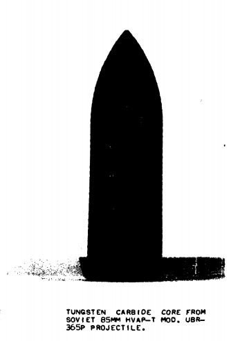
The smaller size and weight of the BR-365P core made it more economical to produce in two ways. Firstly, the amount of material used was less, and secondly, the task of sintering large tungsten carbide products in mass quantities was laborious and skill-intensive. Smaller cores, especially those used in small arms bullets and in later APFSDS ammunition were always preferable from a production standpoint.
The penetration power of BR-365P was intrinsically limited by the poor quality of its light core, though it was compensated by an increased velocity to a very limited extent. Moreover, although the steel carrier body does not directly influence the penetration capabilities of the projectile, given that its shape is highly inefficient for penetrating armour, it still provides a small contribution by transferring a part of its kinetic energy to the core. This is due to the conservation of momentum, made possible by the physical contact between the body and the core.

Upon impact, the front end of the body collapses due to the structural weakening created by the reel shape, but the heavier base continues its forward motion, helping to drive the core into the armour like a hammer on a nail. It is not until the steel body loses contact with the core due to its collapse against the surface of the armour that this effect ceases. This mechanism was mentioned in the report "Review of Soviet Ordnance Metallurgy" and the textbook "Устройство и действие боеприпасов артиллерии". A steel plug can be fitted behind the core of an APCR round to take full advantage of this effect, as exemplified by the 76.2mm BR-354P round. A variant of BR-365P with a steel plug was also developed at some point, but was not serially produced.
Muzzle velocity: 1,050 m/s
Cartridge weight 11.42 kg
Projectile weight: 4.99 kg
Propellant charge weight: 2.85 kg
Overall projectile length: 274mm
Core diameter: 28mm
Core length: 90mm
Core weight: 0.648 kg
| Range (m) | 100 | 300 | 500 | 1,000 | 1,500 |
|---|---|---|---|---|---|
| Penetration at 0 degrees | 167mm | 152mm | 139mm | 108mm | 83mm |
| Penetration at 30 degrees | 124mm | 114mm | 103mm | 80mm | 62mm |
Below 500 meters, the penetration of BR-365P was essentially equivalent to a 7.5cm Pzgr. 40 fired from a PaK 40. At 500 meters and beyond, BR-365P was substantially worse. During the famous Yugoslavian tests, it was found that it could defeat the uper glacis of the M4A3E4 Sherman from 1,200 meters, matching the 7.5cm Pzgr. 40 and surpassing BR-365 by 100 meters. However, it only managed to defeat the turret front from 1,250 meters, whereas Pzgr. 40 could do so from 1,500 meters. Unsurprisingly, BR-365P was incapable of defeating the upper glacis of the M47 or the front of its turret, as discovered during the same tests. The frontal arc of the turret was still vulnerable, as BR-365P could still defeat its front-side from 1,000 meters, but in this case, it had no advantage over BR-365.
With all this in mind, the usefulness of BR-365P usefulness in a postwar battlefield would have been limited on postwar tanks, but considering that it had only a negligible advantage over BR-365 at the same angles of attack, there was practically no point in issuing UBR-365P rounds at all.
52-UBR-367P, PZh
52-BR-367P, PZh

Like the other propellant charges in the 367 series, the propellant of the UBR-367P round contains a bundle of stick propellant, but instead of a loosely packed bundle, it was fitted to the end of the primer. The function of the bundle remained the same, that is, to ensuring the uniformity of propellant combustion. 2.5 kg of propellant is used, like the UBR-365PK round. According to the article "85-мм дивизионная пушка Д-44: Начало золотого века советской артиллерии" (85-mm divisional gun D-44: The beginning of the golden age of Soviet artillery) published in the February 2019 edition of the "Техника и вооружение" magazine, the peak operating pressure developed by BR-367P is 257.9 MPa (2,630 kgf/sq.cm).
For BR-367P, the point blank range on a target with a height of 2 meters is 1,120 meters, almost 200 meters further than the standard APCBC round. Though BR-365P has a higher muzzle velocity, the lower drag of the streamlined BR-367P projectile ameliorates the difference at ranges of 500 meters and above. Beyond 500 meters, BR-367P enjoys a rising advantage in velocity, which, combined with the much greater effectiveness of its core, naturally provided an increase in penetration power.
| Range (m) | 100 | 500 | 1,000 | 1,500 |
|---|---|---|---|---|
| BR-365P (m/s) | 1,018 | 895 | 751 | 623 |
| BR-367P (m/s) | 997 | 909 | 803 | 705 |
In a technical manual for the D-44, the maximum effective range of BR-367P was considered to be 2,000 meters - twice as far as BR-365P. Though the definitions of "effective range" are nebulous, this illustrates the degree of improvement brought by the new shot.
The dispersion of BR-367P is similar if not identical to BR-367.

A pair of copper driving band were fitted to the base of the body. The body of the BR-367P projectile is made from the same structural carbon steel grades as BR-365P. The body is covered with a steel ballistic cap, and the subcaliber core is secured with a steel cap. The main purpose of the cap is to fix the core firmly to the carrier body and to provide a modicum of drop protection for the brittle core from rough handling. It is most likely too thin to protect from spaced armour, with the possible exception of very thin "Schurzen" type skirts.
Compared to the American 76mm M93 HVAP round, the proportional weight of the body is much larger. The smaller parasitic mass of the M93 round can be ascribed to its more sophisticated design consisting of an aluminium body fitted to a steel base. The lag in ammunition technology experienced by the USSR relative to Western military powers was a prevailing theme throughout the Cold War. Nevertheless, the penetration power of M93 was not higher than BR-367P despite its advantageous qualities. There are some possible explanations for this.


Compared to BR-365P, the BR-367P projectile has an even smaller elongation of 3.0 calibers, though it was still somewhat heavier overall due to the larger core. Its tungsten carbide core is 35mm in diameter and 140mm long, giving it an aspect ratio of 4.0. It weighs 1.6 kg, which is more than twice the weight of the BR-365P core while the weight of the complete projectile inceased only slightly to 5.3 kg. However, the weight of the core was still lighter than the core of the M93, which weighed 1.79 kg (3.95 lbs). The BR-367P tungsten carbide core shared the same aspect ratio as the 76.2mm BR-354N core, developed in conjunction with BR-367P and sharing the same design features but scaled for a smaller and less powerful gun.
Muzzle velocity: 1,020 m/s
Cartridge weight 11.72 kg
Projectile weight: 5.35 kg
Propellant charge weight: 2.5 kg
Overall projectile length: 255mm
Core diameter: 35mm
Core length: 140mm
Core weight: 1.6 kg
| Range (m) | 100 | 300 | 500 | 1,000 | 1,500 | 2,000 |
|---|---|---|---|---|---|---|
| Penetration at 0 degrees | 243mm | 228mm | 213mm | 178mm | 148mm | 121mm |
| Penetration at 30 degrees | 177mm | 166mm | 155mm | 130mm | 108mm | 88mm |
Owing to the great improvement in core weight as well as quality, the penetration power of BR-367P was greatly improved compared to the BR-365P, and improved to the extent that it exceeded the 8.8cm Pzgr. 40 fired from a KwK 36 and matched the 76mm M93 HVAP round used in the U.S.
HEAT
The limitations of conventional 85mm anti-tank munitions against the most modern medium tanks of the 1950's was addressed with new HEAT ammunition. The first example of such ammunition for the D-44 was the UBK-367, entering service in 1953. With it, the relatively modest D-44 became a viable postwar anti-tank gun even when faced with the most dangerous threats on the battlefield.
As was expected for postwar HEAT designs, the HEAT shells provided for the D-44 were fin-stabilized. The use of folding fins with a large span rather than fixed fins with a span equal to the projectile diameter, such as the designs used in American HEAT shells, was a design solution to maximize the lift generated by the fins. To give fins the most effective lifting surface, the tail boom should be as small as practical so that a greater portion of the fin is outside of the shell body boundary layer, and the shell body should have a boattail so that smooth uniform flow is presented to the surface.
It is worth noting that fixed fins are easy and cheap to manufacture to precise tolerances because they have no moving parts, which naturally contributes to reduced shot dispersion. However, fixed fins also impose certain design restrictions. A large amount of space is required between the leading edge of the fins and the shell body to reduce fin-body interference and allow the fins to generate their full lift force. This reduces the projectile volume-to-length ratio. If low drag is important, the long boattail required further reduces the useful projectile volume. This is best exemplified by the 90mm M348 shell, which had a tail extending to the very base of the cartridge case.
Folding fins permit projectiles to have a higher volume-to-length ratio than fixed fins designs. Weight and volume savings can thus be obtained, allowing a more powerful charge to be delivered to the target. Moreover, the absence of a long tail boom for the stabilizer fins also increases the rigidity of the projectile, suppresses the vibration and flexing of the tail, and thus prevents damage from scraping against the edges of a muzzle brake. Case in point, the BK-367 shell has a full length of 7.2 calibers, whereas the 90mm M348 shell had a full length of 10.02 calibers. The main disadvantage of folding fins is that they are more complex and expensive to manufacture, and the entire assembly must be built with tight tolerances to minimize the asymmetry of drag forces.
53-UBK-367
53-BK-367

Introduced in approximately 1955, the UBK-367(M) round was not only intended for the D-44, but also for tanks and tank destroyers armed with an 85mm gun. At the time of its introduction, this was largely limited to the T-44, modernized T-34-85 tanks and SU-85 self-propelled guns. Due to its great length of 1.3 meters, as compared to just 908mm for a UBR-367 APCBC round, the cartridge may not fit in some ammunition racks. For a D-44, the length of the cartridge was meaningless.
Designed to destroy tanks, self-propelled guns and other armoured targets, BK-367(M) had high penetration power and allowed the D-44 to combat practically any tank at the time. It was developed from a project in the late 1940's to provide 76.2mm and 85mm guns with ammunition powerful enough to combat modern tanks, resulting in the UBK-354(M) round in the 76.2mm caliber and UBK-367(M). The GKN percussion spitback fuze is used.
Like the 76.2mm BK-354(M) shell for the ZiS-3 and the D-56T tank gun for the PT-76, the muzzle velocity of BK-367(M) is only 550 m/s, owing to a small propellant charge of just 1.3 kg. This modest velocity was a limitation imposed by the deficiencies of the percussion-initiated GKN fuze.
GKN was specifically designed for 76mm and 85mm fin-stabilized HEAT shells, since it was not possible to use a centrifugal arming mechanism as found in the GKV fuze for spin-stabilized HEAT shells. However, its design was still based on percussion initiation with a striker typical for artillery shells, unlike the piezoelectric fuzes being used abroad in the early 1950's. The initiation delay with a percussion fuze is inherently longer than a piezoelectric type, negatively influencing the penetration power of the HEAT shell, and the fuze is not graze sensitive.
Its protective cap must be removed before firing, unless external conditions dictate otherwise. During hailstorms and heavy rain, the cap should be left on. The cap may also prevent the fuze from initiating when passing through thick bushes.

On impact, the large spring-loaded striker is driven back, puncturing the detonator cap. The detonation energy of the initiator cap is transmitted to the initiator charge via a shockwave through the walls of the charge casing, which in turn transmits a shockwave to the booster charge via a membrane. The booster charge sends an explosively formed penetrator (EFP) down the length of the projectile and into the detonator receptable at the apex of the shaped charge liner, finally initiating the primary booster charge and prompting the warhead to explode. The use of an EFP rather than a flame decreases the fuzing delay, which is important during a prolonged delay, because the shaped charge warhead could be deformed as the thin-walled projectile continues its trajectory into a hard target. The fuse works at impact angles up to 60 degrees, which was nominally sufficient for all modern medium tanks of the time, but could be problematic in practice as the target could be positioned obliquely. This performance is the same as the M509 piezoelectric PIBD fuze used in American HEAT shells in the 76-120mm range of calibers.
The implications of the low muzzle velocity were not positive. It eroded an important advantage of the D-44 over recoilless rifles - ballistics. For comparison, the BK-883 HEAT shell fired from the domestic 107mm B-11 recoilless gun had a muzzle velocity of 400 m/s, while foreign weapons like the 106mm M40 and 120mm BAT recoilless rifles had a muzzle velocity of 500 m/s and 450 m/s respectively, implying that their trajectories were not significantly less flat than BK-367(M).
Relative to the conventional AP or subcaliber rounds, BK-367(M) had much poorer ballistics, making it much harder to use on distant and moving targets. The point-blank range of the BK-367(M) against a target with a height of 2.0, 2.7 and 3.0 meters is 630, 720 and 760 meters respectively. The maximum sighted range of the shell is 2,000 meters, achieved with a gun superelevation angle of 2°57'. Its performance only appears favourable if compared to smaller caliber crew-served weapons such as the 90mm M67 recoilless rifle which had a muzzle velocity of just 213 m/s. However, the poorer ballistics of M67 were excusable owing to the short-ranged nature of its role.
To eliminate the stabilizing spin imparted by the rifling of the gun, the projectile has a slip ring and stabilization is achieved with four flip-out fins made from S-50 or S-60 structural carbon steel. The slip ring is made of S-60 carbon steel and is affixed onto the body by a screw-on wedge collar. A copper obturating band is pressed into the slip ring. The slip ring rotates freely as the projectile travels down the rifled barrel, and the low sliding friction between it and the projectile body reduces the rotational energy induced to the projectile. As a result, the projectile only spins at 10% of the full angular speed from the rifling - fast enough for an equilibrium spin, but slow enough to not influence the shaped charge jet coherence.

This solution was better than using a copper slip ring, as the coefficient of sliding friction between dry steel on steel is significantly lower than copper on steel, but it was not the most ideal solution. Nylon obturator bands, as used on American fin-stabilized ammunition of the time, had even less friction on steel and also offered somewhat reduced barrel wear compared to copper bands.
Before the round is fired, the fins of the projectile are kept tucked in by the neck of the cartridge case, and nothing else. The fins remain closed until the projectile leaves the barrel, since the moment of inertia from the linear acceleration of the projectile acting on the fins is greater than the centrifugal moment until the projectile ceases to accelerate once it leaves the barrel. Once acceleration ceases, the centrifugal moment causes the fins to flip open. The fins are not affected by muzzle brakes, and external perturbations have no real effect on the flight of the projectile. Even the reflection of the muzzle blast shockwave from the surface of the ground has no significant effect on the opening of the fins. When deployed, the fins are slightly swept back and are stopped from unfurling further by the base of the tail boom. The fins have bevelled surfaces to maintain the spin of the projectile during flight.
The initial production model suffered from a large dispersion due to a design flaw. BK-367 shells manufactured before 1955 had bevels on both sides of each stabilizer fin. During testing, such projectiles showed a large dispersion of 0.8 mils in the vertical and horizontal planes. Beginning in 1955, new stabilizer fins were built with a one-sided bevel.
Similar dispersion issues were present in the 90mm M348 round, which had fixed fins. It was approved for production in 1949-1950. During research and development, the ammunition performed according to specifications with dispersions of 0.3-0.4 mils at 1,000 yards obtained during testing, but the practical use of M348 rounds revealed that the dispersion would increase to 1 mil due to damage to the low-strength fins at the muzzle as the barrel "jumps" from the recoil.
The warhead casing wall has a thickness of 0.09 calibers at the thickest point. The shaped charge liner is an acutely angled cone with a diameter of 60mm and a cone angle of 24 degrees. The liner has the shape of a funnel to permit the flame from the GPV-2 spitback fuze to reach the base detonator. A-IX-1 is used as the explosive filler. An unusual feature of the time was the inclusion of a wave shaper, an inert wave-focusing lens, in the explosive charge to optimize the propagation characteristics of the detonation wave. This improved the penetration power for a given mass of explosive and permitted excellent performance for a shell of limited caliber.
According to the penetration data given in the munitions design textbook "Устройство и действие боеприпасов артиллерии", the BK-367 shell with a steel liner penetrates just 230mm of medium hardness armour steel, or RHA, whereas BK-367M penetrates 350mm. The basic variant with a steel liner was essentially a fallback option, serving as a more accessible alternative that could still meet the requirement of perforating the armour of any medium tank (considered to be 200mm) in case copper liners could not be produced due to strategic material shortages.
Muzzle Velocity: 550 m/s
Projectile Length (official): 616.75mm (610.83mm without fuze)
Projectile Weight: 9.24 kg (9.066 kg without fuze)
Explosive Filler Weight: 0.979 kg
If judged by penetration power alone, the performance of BK-367M is roughly comparable to contemporary recoilless rifle grenades of a similar caliber such as the 84mm slpsgr m/56 HEAT grenade (310mm RHA) fired from the Carl Gustav. It is also similar to the 90mm M348 shell (304mm RHA flat, 127mm at 60 degrees) and markedly superior to the 90mm M371 HEAT grenade (250mm RHA) fired from the M67. The performance approaches the level of 105mm HEAT shells.
The main factors that gave the Soviet design an advantage in penetration power over American HEAT shells were the larger diameter of the shaped charge cone (made possible by a thin warhead casing), the use of a wave shaper, and the superior characteristics of A-IX-1. The detonation velocity of A-IX-1 (8,450 m/s) is significantly higher than Comp. B (7,900 m/s), and the detonation pressure is also higher, 30 GPa compared to 27 GPa.
3UBK1, 3UBK1M
3BK2, 3BK2M

Like its predecessor, the UBK1(M) round was not only intended for the D-44, but also for tanks and tank destroyers armed with an 85mm gun. This included the SD-44 self-moving gun, the T-34-85 and the SU-85. The shell design is best described as a refined version of BK-367(M). It was introduced in 1961 as the first in the new series of artillery HEAT shells identified by a sequential 3BK GRAU index, with "3" referring to Category 3 of the GRAU index under which artillery ammunition and rockets were classified, replacing the original Category 53 designation that gave the "53-" prefix for artillery ammunition only.
Its main distinguishing factors were a lighter overall weight and the use of a 6-bladed stabilizer fin assembly, which was being used universally for all fin-stabilized ammunition. This permitted a large propellant charge weighing 2.14 kg to be used, propelling the shell to a much higher muzzle velocity of 850 m/s.
The warhead has a conical liner with an A-IX-1 filler, complete with a wave shaper. A major improvement was the use of the GPV-2 piezoelectric spitback fuze, the latest standardized universal fuze for HEAT shells in a range of calibers from 76.2mm to 115mm. Upon impact, the piezeoelectric element experiences a powerful shockwave and converts the mechanical stresses into an electrical impulse. A potential difference of several kilovolts is produced, which is discharged at the electrodes in the spark gap of the spark detonator. This detonates an initial booster charge, setting off the detonator cap through the walls of the steel cavity by transmitting the shockwave of the explosion. In turn, the detonator cap sets off the booster, sending an EFP into the detonator receptable at the apex of the shaped charge liner.

The use of a piezoelectric element instead of a mechanical striker enabled the possibility of initiation on grazing impacts if the fuze grazed the target in such a way that the piezoelectric element was stressed. It also reduced the fuzing delay. Based on tests of 3BK5 shells (with the same GPV-2 fuze) in Yugoslavia, the fuze works at impact angles of at least 62 degrees. For comparison, the M509A1 PIBD fuze of the 90mm M431 HEAT shell was demonstrated to have a very high probability of failing to detonate at an impact angle exceeding 60 degrees during the same tests.
To counteract spin from rifling, the projectile uses a steel slip ring secured to the projectile body by a screw-on wedge collar. One difference from the BK-367(M) is that the slip ring features an iron-ceramic obturating band rather than a copper one. This can be expected to increase the bore erosion rate of 3BK2(M) by 30% compared to a conventional shell, but it is also responsible for slightly increasing the muzzle velocity.

The projectile featured a new stabilizer fin assembly with six fins to provide better shot consistency. 50KhG spring steel was used for the fins. The opening mechanism of the fins remained the same, but the fins have a different design with a canted tip to maintain projectile spin instead of a bevel, and they are not swept back when fully deployed.
The length of the projectile increased to 7.4 calibers, but the weight decreased to 7.35 kg. This was largely due to a reduction in the warhead casing thickness from 0.09 calibers to just 0.07 calibers. Additionally, the thickness of the nose fairing cone was also substantially reduced. The casing thickness reduction also permitted the shaped charge cone to be enlarged to 63mm. Based on the penetration data given in the munitions design textbook "Устройство и действие боеприпасов артиллерии", its penetration power with a steel liner (BK2) and copper liner (BK2M) reached 242mm and 282mm respectively. While the penetration with a steel liner was marginally superior, the copper variant had decidedly inferior performance compared to BK-367M.
This anomalous reduction in penetration power may be explained by the low thickness of the nose fairing cone. Owing to the nature of the operation of a spitback fuze, even a modern design with a piezoelectric element, there is a delay in the initiation of the explosive charge, during which the nose of the projectile may crumple after impact during the action of the fuze booster charge. The crumpling of the nose should be localized as it is not structurally integral to the warhead itself, so the negative effect on jet formation is not critical, but the reduction in standoff distance explains the poorer penetration power relative to BK-367(M) despite the other positive design qualities.

The main upside of the reduced weight is that a much higher muzzle velocity of 850 m/s was achieved. The point blank range on a target with a height of 2 meters is 915 meters, which was a very substantial improvement of almost 300 meters compared to BK-367(M). Velocities higher than 850 m/s only bring very limited, diminishing increases in point blank range. This solved the main issue of BK-367(M), while retaining enough penetration power to fulfill the requirement of combating modern medium tanks, while also having reserve penetration to ensure a meaningful post-perforation effect. As such, despite having inferior penetration, BK2(M) was the superior cartridge overall. It also allowed the D-44 to outclass recoilless rifles, helping to justify the investment into this class of weapon rather than switching entirely to recoilless weapons.
Muzzle Velocity: 850 m/s
Projectile Length (official): 630.07mm (619.7mm without fuze)
Projectile Weight: 7.351 kg (7.221 kg without fuze)
Explosive Filler Weight: 0.935 kg
D-48 (52-P-372)

The D-48 was developed by OKB-9, the in-house design bureau of factory No. 9, under the leadership of F. F. Petrov. Its origins date back to the second half of the Great Patriotic War, when a set of tactical-technical requirements were issued in the spring of 1944 with the objective of the project was to match the ballistics of the German Pak 43. A specific requirement was that the muzzle velocity of the full-bore AP shell for the gun could not be lower than 1,050 m/s. It was mandated by the GAU that a necked case from the 100mm B-34 gun with an increased powder charge had to be used instead for economical reasons.
The first prototype of the D-48 was delivered for state acceptance tests on the 31st of December 1948. Testing began the next year at the Main Artillery Range, but were suspended after 399 rounds as the high-efficiency muzzle brake was reportedly crippling to the gun crew. After the delivery of a new muzzle brake in the second half of April, tests resumed and continued until June 1949. The new model D-48, modified according to the results of field tests, was completed by the factory in April 1950, and then the gun passed comparative tests along with the 85mm S-6 gun, designed at the TsNII-58 research institute under the leadership of G. V. Grabin. The military ultimately chose the D-48, but tests continued and its adoption only took place in 1953.
The first order for 50 guns was issued to factory No. 9 a year later, in 1954, but for unknown reasons, work never began. The design documentation was instead transferred to factory No. 75 in the small Siberian town of Yurga, which had been involved in large gun production during the Great Patriotic War with the manufacture of 122mm D-25 guns in its repertoire, and at the time was engaged in the production of naval gun mounts, anti-tank guns, carriages and mortars. As factory No. 75 was already engaged in the production of D-44 field guns, progress in readying D-48 production was relatively speedy. A pilot batch of 28 guns was built before the end of the year, and the mass production of the D-48 began in earnest in 1955.
The production rate of the D-48 was marginal compared to other towed weapons, and its production run was extremely brief, ending in 1957. A total of just 819 guns were built. Of that figure, 100 guns were the D-48N model featuring a night vision sight, all produced in 1957.
Number of guns produced1954: 281955: 2501956: 2511957: 290 (incl. 100 D-48N)
As it never saw combat against tanks, the capabilities of the D-48 in its primary role are unknown. However, it is known from Soviet testing that the upper glacis of the Panther could be perforated with 8.8cm Pzgr. 39/43 shells at 600 meters. The ability to perform such a feat with a lightweight, high-velocity towed 85mm gun would have been deeply impressive in late 1943, but given that the D-48 only began mass production in 1955, the permissible standards were rather different. Considering that 100mm AP and APBC shells fired from a D10 could accomplish the same feat at more than twice the range, and that the BS-3 field gun with the same ballistics as the D10 already existed since 1944, it becomes very challenging to justify spending resources on a weapon such as the D-48.
On the whole, the BS-3 was ostensibly just as good as an anti-tank gun as the D-48, and it would have been redundant to have two guns filling the same role if not quite wasteful due to the introduction of an additional ammunition type into the logistics system of the Soviet artillery forces. The only tangible advantage of the D-48 is that it had a longer point blank range, but this alone was not enough to justify its existence, and conversely, the limitations of the caliber would have made it impossible to fight modern medium tanks from the front - a fact that doomed the fate of the D-48.
The first guns delivered to the Soviet Army participated in the May Day parade of 1955, towed by AT-P prime movers. This marked the first public appearance of the D-48. It was misidentified as a new 100mm field gun by Western observers and was given the designation of "100-mm field gun M1955". The images below, taken from the report "Summary of Significant Soviet Weapons and Equipment" by the U.S Department of The Army, clearly show the D-48 with its asymmetrically rounded gun shield and bulbous muzzle brake.


As was often the case, intelligence reporting on the D-48 was completely incorrect with a mixture of overestimates and underestimates. Evidently, the existence of a new 85mm gun bearing the "D-48" designation was known from military journals, but its characteristics were not. The motorized SD-44 gun was misidentified as the D-48, and as such, it was assumed that its ballistics were identical to the D-44. Unaware of the development of the new 367-series ammunition, the APHE and APCR rounds were listed as penetrating 111mm and 138mm respectively at 500 meters, corresponding to the BR-365K and BR-365P rounds. Aside from that, the quantity of guns produced was grossly overestimated.

The D-48 was not produced outside of the USSR, and indeed, it was not even produced outside of Yurga. Other than Ukraine, which inherited an unknown quantity of guns that were kept in reserve on its territory before the dissolution of the USSR, only Russia still possesses some D-48 guns, all as museum pieces, monuments, or held in long term storage. The most recent use of the D-48 was in the Ukrainian war where massive losses forced the Ukrainian army to reactivate their reserves, and the restrictions on deploying "heavy artillery" within 50 km of the ATO, defined as having a caliber of 100 or more, made the 85mm D-48 a viable artillery piece.
Overall, the D-48 was largely unsuccessful. The design of its carriage served as a basis for the carriage of the more powerful T-12 gun at the No. 75 factory in Yurga, but that was the entire extent of the impact that the D-48 had on Soviet anti-tank artillery. The gun itself was a complete dead end. Its ballistics were more influential, however. Its ballistics were used as the basis of the D-58 gun, made for the experimental Object 906 light tank, and the D-70 gun, used in the serially produced ASU-85.
DEPLOYMENT
The D-48 replaced the D-44 in the anti-tank battalion of motor rifle divisions, and was organized in the same way. It is difficult to determine when it was fully replaced by the T-12 anti-tank gun, but it appeared to have served for at least some time during the 1960's.
Although it is not directly explained in any literature why factory No. 9 never began work on producing the D-48, the events at the time show that there were already doubts about the usefulness of towed guns, even in this early stage of the Cold War. For one, the SU-100P self-propelled tank destroyer was in development at the same time as the D-48 and had already passed state trials by 1952, and would be ready for service after the correction of design flaws within the next few years.
In the 1950's, the Soviet Army launched a massive modernization effort of its ground forces, with the major focus being the complete motorization of infantry units and their supply chain, leading to the official formation of motorized infantry in 1957. Due to the increased motorization of the infantry, the mobility requirements for divisional artillery increased sharply, and weapons like the SU-100P were much more attractive than towed guns.
The SU-100P even managed to enter service in 1955, but only in name, as its career was cut short prematurely by the start of the reorientation from conventional weapons to missile technology led by Nikita Khrushchev. In fact, it is claimed on page 160 of the book "Вооруженные Силы СССР после Второй Мировой войны: от Красной армии к Советской. Часть 1: Сухопутные войска" by V. I. Feskov et al., that the SU-100P was put into service with the intention of replacing the D-48. It was only after the SU-100P was withdrawn that a void in this niche appeared, and without another promising weapon to fill this void, the D-48 had to suffice.
However, the drawbacks of a towed weapon were ameliorated to a great extent by a change in the doctrinal role of heavy anti-tank guns like the D-48. Such guns, organized into anti-tank battalions, were relegated to the reserves of motorized infantry divisions. Under this doctrine, heavy anti-tank guns were expressedly prevented from directly taking part in fighting, as was often the case in WWII. The innately poorer tactical mobility of a towed field gun compared to a fully tracked self-propelled system in difficult terrain was also overcome by deploying them in reserve units.
An anti-tank battalion was instead used as a defensive reserve in motor rifle divisions, organized into a single anti-tank battalion for a motor rifle division. The anti-tank battalion would normally be held in reserve until the division begins to perform an operational maneuver. When defending against an enemy that has broken through the main forces of the division, the anti-tank guns are brought forward from the reserve and are deployed according to the direction of the main thrust, as determined by the reconnaissance unit organic to the anti-tank battalion. A noteworthy detail is that the enemy tanks are allowed to penetrate deeply behind the lines of the division on purpose, so as to create additional depth with which a stronger defence can be made.
The engineer battalion of the division would be used together with the anti-tank battalion to lay minefields rapidly in the path of the enemy thrust, in order to stop them or at least to slow them down in front of the anti-tank guns.
Heavy towed anti-tank guns were also used to protect communications facilities, outposts, forward operating bases, and other important fixed facilities. Due to the static nature of this role, a towed weapon system is fundamentally not worse than a self-propelled system.
In the offensive, the guns of the anti-tank battalion would trail behind the advancing motor rifle battalions and could be deployed in several ways. When the motor rifle battalions attack a hastily prepared defence, the guns could be deployed to protect the flanks and provide security for the supporting units at the rear of the division, with the objective of preventing a potential encirclement. For such tasks, a self-propelled tank destroyer would have been excessive or completely wasteful. To use a tank or tank destroyer in such a role would reduce the number of self-propelled guns available to be concentrated for the main offensive push, both for the breakthrough and to exploit the breakthrough, while completely squandering the mobility of the system by deploying it in fixed defensive positions.
If the circumstances at the front permitted, anti-tank guns could be called up to supplement artillery units in providing indirect fire support. Indirect fire was a capability that was also provided by contemporary Soviet assault guns and tank destroyers, but to use self-propelled systems for such a role was wasteful. They could instead be used to reinforce the advancing units in the offense by leveraging their mobility to closely support the infantry or be attached to tank units to enhance their firepower against enemy heavy tanks.
MOBILITY


The D-48 would be towed by an AT-P armoured prime mover or a ZiS-151 truck. The newer ZiL-157 may also serve as its prime mover later in its life. It could be towed to a top speed of 60 km/h. On a cobblestone road, the average speed is 35 km/h and the average cross-country speed is 15 km/h. By design, the AT-P was more suitable for combat conditions owing to its small size, armour and integrated bow machine gun, allowing it to bring the gun close to the battlefield and retreat to a hidden position more easily than a truck, and have a much better chance of surviving an artillery bombardment.

The D-48 weighed 2,400 kg in its travelling configuration and 2,350 kg in its combat configuration. This was a large increase in weight over the D-44 and made the system rather burdensome, but for the level of anti-tank firepower provided by the D-48, the level of mobility offered by this weight was unprecedented.
For comparison, the 8.8 cm Pak 43 towed anti-tank gun with a cruciform carriage had a travelling weight of around 5 tons, though it had an "in-action" weight, or combat weight, of 3,650 kg. That said, the combat weight of the Pak 43 was meaningless since its combat configuration involved the conversion of its cruciform carriage to a firing platform by removing its wheels, rendering it totally immobile. The 8.8cm Pak 43/41 gun is a more relevant point of reference as it was built with a split-trail carriage taken from the 10.5 cm leFH 18 field howitzer. As its carriage was chosen out of expediency rather than for optimal characteristics, the Pak 43/41 had a huge weight of 4,389 kg. The D-48 was also lighter than significantly smaller and less powerful foreign counterparts like the 17-pdr Mk. I anti-tank gun, which had a combat weight of 2,957 kg, despite its smaller 76.2mm caliber.
The nearest point of reference among domestic artillery was the BS-3. Weighing 3.65 tons in its combat configuration, it was a whopping 1.3 tons heavier than the D-48. The BS-3 was already quite a light gun, being equal in weight to the 8.8cm Pak 43 in its combat configuration while retaining a modicum of mobility thanks to its split-trail carriage, but even so, the BS-3 was comparatively difficult to manhandle as each gun was assigned with the same number of crew members as a D-48.
However, despite its advantageous size and weight compared to a BS-3, the D-48 was not more flexible in terms of its towed mobility. The BS-3 was still light enough to not require a heavy artillery tractor, and in fact, its designated prime movers were the same vehicles; the wheeled prime mover was the ZiS-151, and the tracked prime mover could be the wartime Ya-12 or the postwar AT-L or AT-P.
CARRIAGE

The low weight of the D-48 was achieved thanks to its lightweight split-trail carriage, which had a complete weight of just 1,250 kg. For comparison, the large carriage of the 17-pdr Mk. 1 weighed a whopping 2,132 kg (4,700 lbs). In truth, the carriage of the 17-pdr could serve as a masterclass in poor design, considering that the 17-pdr gun assembly itself weighed just 825 kg, which was actually marginally lighter than the 3-inch M5 (903 kg), not to mention that the gun was only equivalent to a D-44 in muzzle energy, and it was fitted with a high efficiency double baffle muzzle brake.
The carriage of the D-48 was derived from the D-44, a fact that is abundantly clear when the carriage crossbeam, shown above, is compared with that of the D-44. The two are not totally identical, however - only a fraction of the parts are interchangeable. It is a cast steel girder with an identical shape and identical layout of parts, with functionally identical components. However, the lack of interchangeability extends even to the suspension, featuring new torsion bars, wheel swing arms and axles together with new tyres.

Gusmatic "GK" airless tyres with a sponge rubber core from the ZiS-5 truck were used. The rim flange width and rim diameter were 7 inches and 34 inches respectively. The external diameter of the tyre was 955mm. The width of the axle track (the distance between the centerline of the two wheels) is 1,475mm, and the maximum width of the gun along the hubcaps of the wheels is 1,780mm. Ordinary pneumatic tyres with the same specifications could be used to replace the GK tyres in an emergency.
The ZiS-5 was a historically significant truck of legendary reputation, being the workhorse Soviet commercial and military truck throughout the Great Patriotic War and in the 1950's, with over a million units produced. At the time the D-48 entered production, the ZiS-5 had just ceased production, but it and its offshoots remained extremely prolific and its wheel specifications had become an industry standard. The wheels were well-suited for the weight of the D-48 and they were large enough to ensure sufficient ground clearance and off-road performance.
The suspension locking system of the D-48, designed to reduce vibrations and the "jump" of the gun after recoil, remained the same as on the D-44. The parts of the locking pin are interchangeable.

The primary difference of the D-48 carriage, other than its wheels, was its rectangular trails. The main feature of the trail design is the absence of joints on the corners of the trail. This is unlike the trails of most artillery pieces which are constructed from four separate plates welded or riveted together at the corners. Instead, the D-48 trail design eliminates sharp corners and also avoids having any fastenings contribute to the structural weakening of the trail. The trail consists of a C-beam with rounded corners, reinforced on its top half with a U-beam and on its bottom edge with a flat plate. This is effectively a more efficient form of the common rectangular section design, contributing to the lightening of the weapon system.

The only tangible downside to lightening a powerful towed gun is a somewhat reduced platform stability during recoil, as a heavy gun platform is helpful for damping the recoil, reducing gun displacement and "jump" after each shot. Besides digging in the gun for stability, a design alternative implemented in the D-48 is to lengthen the trails, reducing the angle between the bore axis of the gun and the axis of the trail. This reduces the rotational moment from the recoil force, thus damping the "jump" of the gun system after each shot and reducing the bending moment on the carriage trails. This, in turn, makes thinner trails viable, offseting the weight gain from their increased length. Owing to the power of the gun, the trails of the D-48 carriage were lengthened compared to the D-44, bringing the total length of the weapon to 9,195mm.
However, this solution is not totally free of downsides. Needless to say, a longer towed load is undesirable as it brings additional complications when it is being moved around in built-up or densely wooded areas. Design solutions to counteract the growing length of a gun system with increasing gun caliber and power are typically accompanied by drawbacks. For example, one solution, implemented in the 105mm L119 light gun, is to have a reversible gun mount with no gun shield, allowing the barrel to be locked over the trail for towing. For an anti-tank gun expected to take direct fire, it is not permissible to have no gun shield. Other solutions such as removable spades or folding trails decrease the structural integrity of the trail and can increase the weight of the weapon.
As is customary for postwar Soviet field guns, the D-48 carriage has a castor wheel on its left trail. The long trails give more leverage when they are lifted to deploy the castor wheel.

PROTECTION

The height of the gun when measured up to the gun shield is 1,475mm, and the height of the bore axis from ground level is 830 mm. The height of the bore axis of the D-48 was very low, much lower than the BS-3 gun (1,010mm), as was its maximum height as measured to the tallest point of the gun shield (1,800mm). That said, the BS-3 was a long range field gun that had to be able to conduct high angle fire of up to 45 degrees, which would be incompatible with its long maximum recoil stroke of 1,180mm unless the bore axis height was increased. Otherwise, the breech could potentially strike the ground when firing at the maximum elevation angle.
Nevertheless, even without comparing the D-48 to such a large gun, its silhouette was exceptionally small. The bore axis height of the D-48 was significantly lower than that of the 8.8cm Pak 43 with a cruciform carriage which had a bore axis height of 914mm when deployed, and it is even lower than the Pak 43/41 which had a split-trail carriage and a bore axis of 1,195mm. For a gun of its power, the low silhouette of the D-48 made it exceptionally concealable.
In fact, the bore axis height of the D-48 was even lower than the 57mm ZiS-2, which had a bore axis height of 875mm. The maximum height of the gun was comparable to the 57mm M1 gun, which measured 1,448mm tall. The main downside of such small dimensions is that the gunner must be hunched down to remain behind the cover of the shield and the loaders also have reduced protection when working behind the gun, but on the other hand, this made the D-48 somewhat easier to conceal.
Having the gun situated closer to the ground is desirable as it reduces the mechanical advantage of the recoil force, thus reducing the bending and twisting moment on the trails applied during recoil. In turn, this permits a reduction in the wall thickness of the carriage trails needed to withstand the recoil. Moreover, it reduces the stress on the trails, as the torque from the recoil is reduced.

For a conventional split-trail carriage, lowering the bore axis was practically the only viable solution for these issues. Only a design such as the American experimental 90mm T13 gun on the T9 carriage with the trails hinged to the top of the gun shield could permit better recoil absorption. Interestingly enough, even with this novel design, the T13 was still much heavier than a D-48, weighing in at 3,107 kg.

SHIELD

The gun shield of a D-48 is easily identified by the wavy shape of its top edge, characterized by the three curves on the left side of the shield and two on the right. In terms of its protective capabilities, it does not differ from the D-44 gun shield in a meaningful way.

The D-48N was built with a mount for a night sight and an additional viewport cut in the gun shield for its use, covered with an armoured panel, along with a new armoured panel for the telescopic sight viewing slit. The photo below, taken by Vitaly Kuzmin, shows a D-48N with the distinctive bulging panel for the night sight viewport.

FIRE CONTROL
The fire control instruments used to direct D-48 batteries is unknown, but can be assumed with great certainty to be identical to that used for the D-44. There is no evidence of anti-tank battalions armed with D-48 guns having proprietary fire control instruments.SIGHTING
The sighting instruments for the D-48 were practically identical to the D-44, and as such, they will be examined only very briefly. The D-48 was equipped with an OP2-77 direct fire telescopic sight and had the standard S71 mechanical sight with a PG-1 panoramic optic.
OP2-77
To aim the gun for direct fire, the gunner was provided with an OP2-77 telescopic tube sight. It was nothing more than a standard OP2 series telescopic sight with a new viewfinder insert to display the range markings for the ammunition of the D-48.

It has a fixed magnification of 5.5x and a field of view of 11 degrees. Its viewfinder is only marked for AP and both types of HE-Frag; there is no range scale for HEAT ammunition, even though it could be fired from the D-48. In such cases, a conversion table would normally be used to allow range adjustments based on the range scale of another shell type.


NIGHT SIGHT
As mentioned before, the artillery and armoured vehicles of the Soviet ground forces gained a night fighting capability in 1957, and the D-48 was not entirely left out. But because the advent of viable infrared night vision sights only occured after the D-48 was nearing the end of its short production run, the number of guns built with the necessary fittings was very limited.
As the basic D-48 lacked the provisions to mount this equipment, the updated model was given a new designation, the D-48N (52-P-372N) to differentiate it from the basic model. D-48N guns were equipped with the APN-3-77 (1PN5) night sights. The APN-3-77 is nothing more than a standard APN-3 series sight with a new viewfinder insert with the range scales for D-48 ammunition.
The two photos below, from the RecoMonkey website, shows the night sight and IR spotlight mounting frame on a D-48N (left) and the power supply control box installed on the gun shield (right), albeit in a rather poor state with the cover missing.


The image below shows the viewfinder markings of an APN-3-77 sight. The reticle consists of a chevron with two vertical dashes for windage adjustments, and below the chevron is a vertical line and a horizontal line in an inverted "T" shape. The gunner adjusts the position of the reticle by turning a range dial to lower the reticle along the range scales until the horizontal line aligns with the desired range for the appropriate ammunition type. The range scale on the left is used for both AP and HE, as they are practically ballistically matched for up to 1.6 km. The range scale on the right is for reduced charge HE.

GUN

Fires the unitary 85x708mm cartridge. The muzzle energy was, however, considerably reduced compared to a BS-3 field gun - only 5 MJ compared to 6.36 MJ. The D-48 was effectively a direct equivalent to the 8.8cm Pak 43 gun. It fired a slightly lighter round, but at a higher muzzle velocity.
The D-48 was effectively an entirely new product with no direct commonality with existing guns. A small portion of its components were unified with the D-44 and BS-3, including the outer casing of the recoil buffer and recuperator, a spring for the breech block, and a large number of nuts and bolts. But aside from such parts, no major assemblies were interchangeable.
The D-48 has a semi-automatic action with a vertically sliding breechblock, opened with a large lever on the right of the breech. The firing mechanism is completely mechanical, with a firing pin and striker. The image on the left shows the cocking of the extractor and breech closing mechansim during recoil, and the image on the right shows the resetting of the mechanism during counter-recoil. This mechanism is conspicuously different from that of the D-44.


According to the norms, the aimed firing rate of the D-48 is 25 rounds in 3 minutes, giving an average of 8-9 round per minute. The maximum rate of fire is much higher - up to 15 rounds per minute.

The mounting system permits the gun to be traversed by 27 degrees to each side, and elevated from a maximum depression angle of -6 degrees to a maximum elevation angle of +35 degrees. This was essentially the same as the D-44 gun, which is quite remarkable considering the large increase in firepower. The traversing arc of 54 degrees was good for a towed anti-tank gun of this caliber and power, and the elevation limit of +35 degrees is far above the requirements of an anti-tank gun.
As with the D-44, the gun cradle of the D-48 is a cast steel cylindrical unit with reinforcing ribs for rigidity. Inside the cradle are riveted bronze inserts and half-ring sections to guide the barrel during recoil. These inserts have grooves for lubrication with grease, topped up from lubrication ports on the sides of the cradle.


The weight of the gun, which consists of the barrel and the breech assembly, amounts to 1,200 kg. The weight of the recoiling parts is 1,265 kg. The weight of the gun tube - which includes the barrel, muzzle brake and the breech assembly - is 1,200 kg. This is 67% greater than the D-44 divisional field gun - a large increase, but well within expectations due to the difference in the barrel length and thickness to accommodate the size and power of the cartridge.
A pneumatic equilibrator of identical design to the D-44 equilibrator was used on the D-48, installed on the right side of the gun at the same location as on the D-44. As before, the equilabrator is a push-type device, which is somewhat counterintuitive as the long barrel implies that the gun should be muzzle-heavy. The normal pressure in the balancing mechanism at a maximum barrel elevation angle is 97 ± 5 kgf/sq.cm (9.512 MPa). This is just under twice the pressure of the D-44 equilibrator, evidently because to the larger weight - particularly the forward weight - of the D-48 due to its long barrel. When the ambient temperature changes, the pressure in the balancing mechanism is regulated with the compensator valve.


The total length of the D-48 gun, including the muzzle brake, is 6,290mm or 74 calibers. It is slightly shorter than the 8.8cm Pak 43 in terms of total length (6,576mm) but due to its marginally smaller caliber, the proportional length is almost the same (74.7 calibers). The rifling has 32 lands and grooves and has a twist of one in 35 calibers. Overall, the barrel has a length of 5,602mm, making the D-48 an L/65.9 gun, and the rifled length of its bore is 4,900mm (57.6 calibers). This is equivalent to the Pak 43 and is 40% longer than the D-44. For comparison, the barrel length of the Pak 43 is 6,017mm (68.37 calibers) and the rifled length of its bore is a 5,125mm (58 calibers). The slightly shorter length of the D-48 barrel is entirely due to the shorter chamber.

The length of the chamber from the end of the barrel to the start of the rifling, is 702mm. This is slightly shorter than the 720mm length of the BS-3 chamber. However, the chamber capacity is 7.987 liters, which is slightly larger than the 7.9-liter capacity of the BS-3 gun chamber, contrary to expectations given the smaller caliber.

When firing an APCBC round, a maximum nominal operating pressure of 304 MPa (3,100 kgf/sq.cm) is developed under standard conditions at a propellant charge temperature of 15°C. This is slightly more than the Pak 43, which was rated for a maximum pressure of 3,000 kgf/sq.cm at the same propellant temperature.
RECOIL MECHANISM

As with the D-44, the proprietary recoil mechanism of the D-48 uses a hydropneumatic recoil recuperator paired with a recoil buffer. The layout and functions are identical to the type used on the D-44. The buffer contains 4.85 liters of Steol-M synthetic hydraulic fluid while the recuperator is filled with 3.6 liters. The recuperator is pressurized to 55 atm. The gun has a normal recoil stroke length of 720mm, with a maximum of 730mm. When firing reduced charge rounds, the recoil stroke length is reduced to 475-625mm.
The drawing on the top, shown below, is the buffer. Below it is the recuperator.


An important innovation with the buffer mechansim was the addition of an air pocket in the hollow piston rod. This was done by underfilling the buffer, leaving a small chamber which is filled with pressurized air. The air pocket provides enough free volume for the hydraulic fluid in the buffer to expand as it heats up, thus self-regulating the working volume of fluid. The fluid in the buffer can expand or contract in volume due to changes in temperature from the environmental conditions, leaky seals, or simply from firing the weapon.
Overall, the air content takes up 2-3% of the total volume in the buffer. During recoil, the air inside the piston rod is compressed by the pressure of the fluid displaced from the reservoir and allows the fluid to occupy its volume until equilibrium is reached. During counter-recoil, the air decompresses and refills the volume evacuated by the fluid.
This feature removed the need to regularly top up the hydraulic fluid or install a fluid replenisher mechanism to regulate the fluid volume in the buffer. A replenisher may not be needed on light guns, but more powerful field guns often required one. They are used on weapons such as the 25-pdr, and the 1981 edition of TM 9-3305 "Principles of Artillery Weapons" states that all medium and heavy guns in service in the U.S Army except the M109(A1) had a replenisher.
The drawings on the left and right below show the recoil and counter-recoil cycle of the buffer (left) and recuperator (right). Note the air pocket depicted in the buffer on the top left drawing.

Apart from the recoil system, recoil control was also aided by the somewhat unusual "pepperpot" style muzzle brake. It consisted of an oversized tapered chamber with perforated walls. This brake replaced the double baffle brake originally used on the first D-48 prototype. This type of brake had a high efficiency of 68%.
This type of muzzle brake is known as a "reactive" brake owing to its predominant use of gas jets instead of baffles. Almost no writings have been published on the technical details of the specific muzzle brake design of the D-48 gun, so all information must be gained from observations alone.

It is worth noting that the front wall of the oversized chamber may act as a baffle, utilizing the reflection of the muzzle blast shockwave and overpressure from the exiting propellant gasses to generate a forward force. However, the small surface area of this wall inherently limits the efficiency of the muzzle brake as a baffle. Rather, the majority of the braking force produced by this muzzle brake is from gas jets, as the official description of the brake indicates. Angled vent holes drilled into the sides of the chamber redirect the exiting propellant gasses in a rearward direction, thus generating a forward thrust. The mild flaring of the brake may be to facilitate the rearward deflection of gasses. Combined with the front wall acting as a baffle, the efficiency of the brake can be quite high.

Its efficiency of 68% was higher than the majority of common muzzle brakes designs, including the myriad of double baffle brake varieties such as the TsAKB brake used on the D-44, the bulbous brake of the 17-pdr, and the standard German-style design, to name the most well-known. It reaches the efficiency of slotted active-reactive multi-baffle brakes. However, as it was chosen over the original double-baffle prototype brake tested on the earliest D-48 guns, the muzzle blast produced by this brake was evidently not as adverse as baffled high-efficiency brakes.

85x708mm ammunition was equivalent to 100x695mm ammunition in bulk, though it was still lighter. This is entirely due to the much lighter projectiles, as the case and propellant charge are closely comparable. The mass of the propellant charge for a full charge round like UBR-372 or UOF-372 is 5.36 kg. This is only marginally less than the 5.5 kg of propellant contained in the 100mm UBR-412 and UOF-412 rounds.
A standard unit of fire for the D-48 consisted of 44 AP rounds, 8 full charge HE-Frag rounds and 48 reduced charge HE-Frag rounds.
A standard unit of fire for the D-48 consisted of 44 AP rounds, 8 full charge HE-Frag rounds and 48 reduced charge HE-Frag rounds.
AP
The only AP round created for the D-48 to rely on kinetic energy to break through armour was the UBR-372. Subcaliber ammunition was not available, nor were any created for the later D-70 gun used in the ASU-85.
A phlegmatizer was included to reduce bore erosion.
53-UBR-372
BR-372

In terms of kinetic energy, the BR-372 shell lay in between the 8.8cm Pzgr. 39/43 and 20-pdr APCBC Mk. 1, but on account of its smaller projectile diameter, its specific impact energy is on par with Pzgr. 39/43. Its large propellant charge of 5.56 kg propelled it to the highest muzzle velocity among the three - 1,040 m/s.
The point-blank range of the BR-372 against a target with a height of 2, 2.7 and 3.0 meters is 1,200, 1,400 and 1,470 meters respectively. This is effectively identical to the Pzgr. 39/43 round fired from the 8.8cm Pak 43 gun. At distances exceeding this, the BR-372 round has a negligibly flatter trajectory, as the firing table for Pzgr. 39/43 round shows it had a point blank range of 1,400 meters on a target with a height of 2.8 meters. For comparison, the point-blank range of the BS-3 field gun when firing the BR-412D round on a target with a height of 2.7 meters is 1,220 meters.
The cartridge is fitted with the new KV-5 percussion primer, undoubtedly because the normal operating pressure of UBR-372 (304 MPa) already reached the maximum rated pressure of the KV-4 primer, so there would be no safety margin whatsoever.

Aside from the name, the BR-372 shell is practically identical to BR-367 and it was fitted with the same DBR-2 base fuze. The design and dimensions of the armour-piercing cap, ballistic cap, penetrator body, and base charge are all basically identical. The only difference was the widening of the copper obturator and driving bands and the corresponding changes in the cuts to the penetrator body to accommodate them. This minor modification gave the shell a slightly greater weight of 9.227 kg, just 27 grams heavier than BR-367.

BR-372 has a total projectile length of 3.64 calibers, excluding the protruding base fuze and tracer. Its AP cap has a length of 0.98 calibers, and has a thickness of 0.35 calibers, covering 0.63 calibers of the penetrator nose. The ballistic cap is attached to the AP cap with a double crimp. The base charge is identical, and the same DBR-2 base fuze is used.
The penetration power of BR-372 against FHA, calculated using the deMarre formula with K=2,400, is shown in the table below.

The penetration of BR-372 at 2,000 meters corresponds to the penetration of BR-367 fired from the D-44 at 100 meters.
Muzzle Velocity: 1,040 m/s
Cartridge Mass: 21.8 kg
Projectile Mass: 9.227 kg
Explosive Charge Mass: 0.05 kg
Projectile Aspect Ratio: 3.64 calibers
As mentioned earlier, Soviet testing found that the upper glacis of the Panther, which was 85mm thick and sloped at 55 degrees, could be perforated with 8.8cm Pzgr. 39/43 shells at 600 meters. Though not precisely identical to Pzgr. 39/43 in design, BR-372 can be expected to break through the same armour at the same distance. For a D-48, Panther tanks were not a relevant threat whatsoever, but it serves as a good analogue of the Centurion as it had just 76mm RHA sloped at 57 degrees on its upper glacis, with the exception of uparmoured models.
For comparison, during tests in 1945, the D10 gun firing the BR-412 sharp-nosed AP shell could perforate the upper glacis of the Panther at a range of 1,200 meters but failed at 1,500 meters. Meanwhile, an experimental blunt-nosed shell with a ballistic cap (APBC), most likely BR-412B which was still undergoing development in 1945, could perforate the upper glacis at 1,500 meters but failed at 2,000 meters.
That said, the turret of a Centurion was much more vulnerable. The front, being flat and only 6" thick, can be considered enough to stop 8.8cm Pzgr. 39 fired from a Kwk 36 or BR-367 fired from a D-44, but it would be wholly insufficient against the likes of the D-48 out to 2 kilometers. Even glancing blows could achieve a firepower kill with ease.
Firing trials detailed in Report No. A.T.317. "Centurion Mk. 2 Defensive firing trial" included tests where five shots of 8.8cm APCBC (from a Kwk 43) were fired at a Centurion turret to obtain glancing blows on the sides of the turret at velocities guaranteeing non-perforation, from 764 m/s to 910 m/s and at angles of 60-65 degrees to the normal. With the first hit, the loader's periscope was damaged and the ocular prism and its protective glass of the gunner's sight (AFV sight Mk.1) shattered, and the second hit fractured and jammed the sight body and range drum as well. The fifth hit even managed to knock out the turret traverse gearbox, and the cumulative damage of all five hits cracked the weld between the turret side and the turret roof.
Moreover, as part of the firing trials, a 17-pdr APCBC shot was fired at the gun mantlet at an angle of 30 degrees to the normal, at a striking velocity of 777 m/s. The shot lodged in the armour, but its impact shattered the prism assembly of the gunner's sight and fractured the mantlet trunnion, completely jamming the mantlet and gun elevating gear. At a range of 3,100 meters, the impact energy delivered by BR-372 will be equal to this test case. It is worth noting that the Mk. 2 was the first serial turret design and its armour scheme was used for all Centurion marks until the Mk. 8, when the "resilient mantlet" was introduced.
In essence, any hit from a D-48 on the frontal arc of a Centurion turret will have a very high probability of achieving a firepower kill, with a mantlet hit at any feasible range being likely to achieve a total firepower kill. At combat distances of a kilometer or more, the armour itself is likely to be perforated.
However, by the time the D-48 was being delivered to the troops, the Centurion was far from the best protected tank available to the European NATO member states. There was also the M47 and M48 Patton tanks to consider.
According to Yugoslavian test results retrieved and published from the Yugoslav archives in Serbia by Bojan Kavedžić, the upper glacis of the M47 Patton, which had a thickness of 102mm (3 inches) and was sloped at 60 degrees, could be perforated by the M39 round (presumably Pzgr. 39) fired from an 8.8cm Pak 43 at 250 meters while the turret front, having 160mm of rounded armour, could be perforated from 1,250 meters, which is not too bad, all things considered. However, due to the needle-nose shape of the turret, its frontal arc had dismal protection; the M39 round could defeat the turret at any range.
Against a more modern target such as the M48, the BR-372 shell had no chance of defeating the upper glacis. That said, the frontal arc of the hull was still vulnerable overall. As expressed through the 85mm BR-367 round, the lower glacis of an M48 Patton can be perforated (solid curve 1) at an impact velocity of 820 m/s, corresponding to a firing distance of 2,100 meters, and it achieves nominal defeat (dotted curve 2) at an impact velocity of 760 m/s, corresponding to a firing distance of around 2,400 meters.

At a side angle of 45 degrees, the upper side of the hull can be perforated (solid curve 3) at an impact velocity of 900 m/s while the lower side can be perforated (solid curve 5) at an impact velocity of 760 m/s. These velocities correspond to ranges of 1,300 meters and 2,600 meters respectively.
The M48 turret maintains a line-of-sight (LOS) thickness of 7 inches (178mm) with a variable thickness of cast steel sloped at a progressively increasing obliquity from 20 to 45 degrees. In general, the turret armour does not offer sufficient thickness to stop BR-372 from a distance of 1,000 meters. Due to the somewhat unusual design approach taken by the Chrysler Corporation engineers, the turret ring region was particularly weak as the turret was mounted on a raised collar housing the turret ring, while the base of the turret itself had a rather tall, 2-inch deep cut to enable the nuts of the turret ring mounting bolts to be fastened. This region would be vulnerable to BR-372 from a distance exceeding 2,000 meters.
As such, while the M48 had sufficient armour to ensure immunity against medium tanks of the previous generation (T-34-85) and light field guns (D-44), modern weapons such as the D-48 were a threat. This is partly because the grade of cast steel used on the M48 did not change from the M47 and remained softer than the armour of the M26 Pershing. According to Brinell hardness testing of an M48A3, the turret gave an impression diameter of 4.20-4.25 (201-207 BHN) while the hull front gave an impression diameter of 4.15-4.20 (207-212 BHN). This is totally consistent with other sources stating that the nominal hardness of the armour was 210 BHN, meaning that the hardness was not increased from the level reached on the M47.
The use of low hardness steel was not necessarily detrimental against large caliber steel AP shells, but its effectiveness was conditional on several factors. For armour sloped at a high obliquity, toughness is the critical factor, and low hardness steels tend to be ductile but strong, and therefore tough. However, the steel of the M26 and M46 was abnormally soft and the armour obliquity was very modest. This is especially true for the turret which was practically flat except for the upper and lower edges of the gun mantlet. For such zones, medium or high hardness armour is the most suitable. According to a Soviet study, found that high hardness armour with a thickness of 110-160mm (at 0-55 degrees) and 130-190mm (at 0-50 degrees) had an advantage over medium hardness armour in resisting 75mm and 88mm projectiles with a muzzle velocity of 1,000 m/s.
On the upper and lower glacis specifically, the low hardness cast steel used on the M48 tank was optimal for resisting larger caliber APCBC shells as a larger amount of energy would be required to pierce it compared to a smaller caliber one. Although the 100mm BR-412D shell had high penetration performance on flat and sloped RHA plate, ostensibly better than BR-372, the lower glacis of the M48 could be perforated by BR-367 at an impact velocity of 820 m/s whereas BR-412D required an impact velocity of 750 m/s. This means that to accomplish the same task, BR-412D would have to possess 4.4 MJ of kinetic energy whereas BR-367 would require just 3.09 MJ. However, the armour was far less effective against Soviet blunt-tipped shells. BR-412B required an impact velocity of just 660 m/s to perforate the lower glacis, translating to 3.45 MJ of kinetic energy.
According to the Yugoslavian test results cited earlier, the 100mm BR-412B shell fired from a D10-TG could perforate the upper glacis from 750 meters and the turret front from 950 meters. The advantage of the BR-372 shell in penetrating low obliquity armour compared to the BR-412B blunt-tipped APBC shell was evidently responsible for providing better performance against the turret of the M47, but its drastically inferior sloped armour penetration was a serious detriment. This was responsible for its deficient performance against the upper glacis, and in general, low obliquity armour was becoming increasingly difficult to find on the modern battlefield.
HE-Frag
For this reason, HE-Frag rounds were supplied to D-48 guns to ensure that each gun battery was capable of handling the full range of expected threats on the battlefield. HE-Frag rounds were ideal against soft targets, and reduced charge rounds in particular were needed when firing at troops in the open as otherwise, the high velocity of the shell would cause unintentional ground ricochets. The full charge HE-Frag rounds are more suitable for hitting armoured personnel carriers.
Unlike the D-44, cast iron shells were not viable. Presumably the high firing velocity would have been too stressful for a cast iron projectile, even with a reduced propellant charge.
UOF-372, UOF-372U
OF-372, OF-372U


In what appears to be a indexing error, OF-372 was officially classified as a HE-Frag shell (OF) rather than a Frag shell (O) as its characteristics indicate. Both the full and reduced charge rounds are paired with the same OF-372 shell.

The full charge round with 5.43 kg of propellant generates 3,000 kgf/sq.cm of pressure and the shell attains a muzzle velocity of 1,010 m/s. The reduced charge round had 2.5 kg of propellant, generating 2,800 kgf/sq.cm of pressure and propelling the shell to a much lower muzzle velocity of 770 m/s. With the full charge round, the D-48 could achieve an impressive range of 18,970 meters. The reduced charge round gave a maximum range of 1,4770 meters.
OF-372 is differs considerably from the O-365K shell, being shorter and slightly lighter, but having the same weight of explosive filler.

The weight of a complete projectile is 9.66 kg, and it contains 0.74 kg of TNT filler. Compared to O-365, it can be expected that the fragmentation effect is not worse, as the proportion of filler weight is hardly different. The MG-N fuze is used. OF-372V shells are fitted with the V-429 fuze instead.
UO-372 (UO-372U)
Muzzle Velocity: 1,010 m/s (770 m/s)
Cartridge Mass: 21.8 kg (18.6 kg)
Projectile Mass: 9.227 kg
Explosive Charge Mass: 0.741 kg
Projectile Aspect Ratio: 4.1
HEAT
While HE-Frag ammunition would be ideal for eliminating dismounted infantry, the limited supply of them meant that HEAT ammunition may be used as a substitute, but with a much weaker effect.
3UBK5, 3UBK5M
3BK7, 3BK7M

The 3BK7(M) shell design belongs to the same developmental series as 3BK2(M) and shares all of the same major design features, but with differences in minor details. It features a 6-bladed stabilizer fin assembly with a steel slip ring, the GPV-2 piezoelectric spitback fuze, and has the same aerodynamic form.
The distinguishing feature of 3BK7(M) among the HEAT shells of the time was its slightly higher muzzle velocity of 925 m/s. The projectile is light, weighing only 7.22 kg. The A-IX-2 explosive charge was also lighter than 3BK2(M), weighing only 0.694 kg. The projectile has a particularly short length of just 6.68 calibers.

Much like the preceding 85mm HEAT shells for the D-44, the 3BK7(M) projectile uses a steel slip ring, but with several design refinements. The main improvement was the switch from a wedge collar to a simple nut for securing the slip ring, and the obturator band was changed back to copper from the iron-ceramic type used in 3BK2(M). Moreover, the the new design of the shell had the slip ring located around the base of the warhead cavity rather than the solid steel base of the projectile. The simplification of the slip ring assembly and refinement in the design of the warhead casing evidently saved some weight and helped shorten the projectile.
According to the penetration data given in the munitions design textbook "Устройство и действие боеприпасов артиллерии", 3BK7 penetrates 240mm RHA and 3BK7M penetrates 280mm RHA. Officially, 3BK7 is rated to penetrate 192mm of medium hardness armour set at 30 degrees, but the rated penetration for 3BK7M is unknown.
Muzzle Velocity: 925 m/s
Projectile Weight: 7.22 kg
Explosive Filler Weight: 0.694 kg
T-12 (2A19), MT-12 (2A29)

When it entered service in 1961, the T-12 replaced the D-48 and BS-3 as the primary towed anti-tank gun of the Soviet Army. It is notable for being the first towed smoothbore anti-tank gun as well as the first smoothbore gun anti-tank gun to enter service anywhere in the world. Only a few months later, the T-62 would enter service with an even more potent 115mm smoothbore gun. The T-12 was created by the in-house design bureau of factory No. 75 by V. Ya. Afanasyev and L. V. Korneev. The development of the T-12 started in 1957, in conjunction with the termination of D-48 procurement. Ammunition for the gun began development in 1958.
According to the article "РАПИРА. Как рождалась знаменитая пушка" ("Rapira": How the famous cannon was born) published by the Donetsk-based YuMZ gazette, the task of creating a 100mm anti-tank gun with high armour penetration was assigned to engineers of factory No. 75 by GRAU. The objective was to overcome the armour protection of existing and prospective tanks of potential enemies. The rationale for the mandate to increase the caliber from 85mm to 100mm is not disclosed in literature, but in general, when limited by the length and design pressure of the barrel, a larger caliber is critical in providing growth in the capabilities of the weapon. For KE munitions, a larger caliber allows a higher muzzle energy to be achieved without requiring higher operating pressures, and for HEAT rounds, a larger shaped charge improves penetration.
Factory specialists began by working on an experimental model and performed research work, then proceeded to experimental development. According to the website of the Yurginsky Mashzavod, design documentation for the serial production of the T-12 was prepared in 1959. After four years of development, the gun passed military tests in 1961. Under decree No. 749-311 issued on the 17th of July 1961, the T-12 anti-tank gun (2A19) was accepted into service and was assigned the moniker of "Rapira". Alongside it, the 2A19-1 and 2A19-M variants also entered service.
The 2A19 is the basic version of the T-12. According to the GRAU index, there exists a 2A23 variant, which is a T-12 with no fixture for a night sight. It is unknown if this variant was serially produced for the Soviet Army. The T-12 can be difficult to distinguish from the D-48 with total certainty, since the presence or absence of a night sight mount may not be a reliable indicator because the D-48N variant exists. The images below, taken from the October 1997 issue of the "Техника и вооружение" magazine, shows a D-48 on the left and a T-12 on the right. In the original article, they were misidentified and are labeled as the opposite. From this perspective, the bevel of the D-48 breech is the best identification detail.


It was replaced by the MT-12, or 2A29 in 1970. The MT-12 can rightfully be considered the zenith of towed anti-tank gun evolution, if not by its technological merits, then by default, as it had no serious competitors, whether domestic or foreign. According to the technical manual for the MT-12, the barrel, the breech block, its opening and closing mechanisms, the recoil mechanism, convoy lights and sighting devices of the MT-12 and T-12 guns have no structural differences. Only the carriage, equilibrator and gun shield was changed.
The T-12 and MT-12 was used within the Warsaw Pact and by Soviet satellite states, including the GDR. The photo below shows a Hungarian MT-12.

At the time the T-12 entered service, the 73mm SPG-9 recoilless gun also entered service to replace both the 82mm B-10 and 107mm B-11 as the battalion level anti-tank weapon as it was lighter, fired faster, had a longer range, and still had more than adequate penetration power. Relative to the D-48 that it replaced, the T-12 can be described as the opposite of what the SPG-9 represented. While the light anti-tank weapons became lighter, the heavy guns became heavier.
The replacement for the D-48 inevitably had to gain weight to cope with modern tank armour. The D-48 was exceptionally light, exceptionally powerful, and exceptionally concealable for a weapon of its power - in all regards, it was essentially an ideal towed anti-tank gun. However, all of that becomes irrelevant if the gun is fundamentally ill-equipped to perform its duty. Interestingly enough, the T-12 entered service with APFSDS and HEAT as the only available ammunition types. Its APFSDS ammunition was the first of its type to receive GRAU designations according to the newly established indexing system, with the 3UBM1 and 3UBM2 both predating the 115mm 3UBM3 round for the T-62. Its HEAT round was the second of its type, being indexed 3UBK2, as it appeared only slightly later than the 85mmm 3UBK1 round. It was followed by the 115mm 3UBK3 round for the T-62. However, the first 100mm HE-Frag round for the T-12 was indexed as 3UOF3, meaning that the 115mm 3UOF1 HE-Frag round for the T-62 predated it. From this, it is known that there was an indeterminate period of several years where the T-12 had no HE-Frag ammunition. Based on the fact that a provisional firing table specifically for 3UOF3 exists, as well as the fact that a revised firing table was published in 1967, it can be deduced that the 3UOF3 only became available in 1967.

If evaluated purely in terms of muzzle energy, the performance of the T-12 was far from unprecedented at the time of its introduction. The muzzle energy of the T-12 when firing a subcaliber round was less than a full charge round from a BS-3. As the domestic munitions manufacturing technology improved to the extent that 100mm APDS for the D10 gun became available, the lack of a muzzle energy advantage in the T-12 became apparent. It delivered just 5.33-5.45 MJ of kinetic energy with its APFSDS rounds, while the BS-3 could potentially deliver 5.70 MJ if it were to fire a comparable APDS round, based on the D10 gun firing a 3UBM6 round as a reference.
In the specific context of the time period, the advantage of the T-12 over the BS-3 was that it was optimized to fire saboted subcaliber rounds, could have a longer barrel life, and provided the conditions for viable APFSDS ammunition to enter service with existing technology, years before APDS and rifled APFSDS ammunition for the 100x695mm caliber reached maturity.
With the discrepancy between the T-12 and the BS-3 being so minor, it is quite evident that the ballistic performance of the T-12 was not at the same level as high velocity 100mm guns like the French SA 47 and the domestic U-8TS. The SA 47 was rated to fire a 15 kg projectile at a muzzle velocity of 1,000 m/s, while the U-8TS (D-54TS) was rated to fire a 16.1 kg projectile at a muzzle velocity of 1,015 m/s. Domestically, the only towed 100mm gun to exceed the muzzle energy of the T-12 and BS-3 was the experimental D-46, developed by the OKB-9 design bureau under the leadership of F. F. Petrov. The D-46, operating at a very high pressure of 392 MPa (4,000 kgf/sq.cm), fired a full-bore AP shell weighing 17 kg at a muzzle velocity of 1,000 m/s.
However, the T-12 could match the penetration power of the D54 gun without requiring the enormous performance, which in turn required large gain in weight due to a thickened barrel and breech together with a larger recoil system. Because of this, the 100mm D54 weighed 635 kg more than the D10, gaining a 120 m/s of velocity in return.
Among existing in-service guns, the closest counterpart to the T-12 was the Czechoslovakian 100mm vz. 53 anti-tank gun. According to the VHU (Military Historical Institute Prague), the vz. 53 gun had a muzzle velocity of 955 m/s as compared to the BS-3 with a muzzle velocity of 900 m/s, achieved using a modified APCBC round (1 kg lighter than BR-412D). In technical characteristics, the gun itself did not exceed the BS-3. However, the gun was accompanied by a number of drawbacks - the new carriage and gun cradle gave the gun a tall bore axis height of 1,250mm, and the weight of the gun increased by over 600 kg compared to the BS-3. In a combat configuration, the vz. 53 weighed 4,210 kg, and in a travel configuration, it weighed 4,280 kg. As such, it made for a rather cumbersome anti-tank gun, though it at least had the benefit of not requiring proprietary 100mm ammunition like the T-12.
The Romanian 100mm M1977 gun was more optimized for the anti-tank role than the old BS-3 by virtue of having a lighter and shorter carriage, but it was still taller than a T-12, having a bore axis height of 900mm, and it offered no firepower advantage as it was ballistically identical to the BS-3.
In the article "Отечественная противотанковая артиллерия - Часть II: послевоенная противотанковая артиллерия" (Domestic anti-tank artillery - Part II: postwar anti-tank artillery) published in the October 1997 issue of the "Техника и вооружение" magazine, it is reported that in 1967, Soviet specialists came to the conclusion that the T-12 would not ensure the reliable defeat of the new Chieftain and MBT-70. Therefore, in January 1968, the OKB-9 design bureau headed by F. F. Petrov was instructed to develop a new, more powerful anti-tank gun with the ballistics of the 125mm smoothbore D-81 tank gun, created by the same design bureau. The D-81 itself was created due to the same concern that the 115mm gun of the T-62 would be insufficient against the Chieftain.
Work on this project culminated in the creation of the D-13 (2A45) "Sprut" gun. However, though the "Sprut" was officially accepted into service, only a small batch of guns were built and delivered to the Soviet Army, all of which were used for troop trials only. There was no replacement for the T-12 other than its own derivative, the incrementally improved MT-12 from 1970. However, the protection of the Chieftain was greatly exaggerated by Soviet intelligence, and the MBT-70 project failed to yield a replacement for the legacy tanks used by the U.S and West Germany.
Though the M60A1 and Chieftain could stop the basic APFSDS ammunition of the T-12 on their most resilient zones, at least in theory, the vast majority of their frontal arcs were insufficiently armoured. If the need arose, they could fall back on their HEAT rounds to deal with these tanks. As such, even though the effective range of the gun shrank against these heavily armoured tanks compared to the threat tanks of the 1950's, and the options of firing angles for a successful attack diminished somewhat, the T-12 and MT-12 could still adequately fulfill their role.
In the 1980's, the situation changed. New main battle tanks were entering service. The MT-12 was even used as the basis of the 2S15 "Norov" tank destroyer with a radar FCS, but after a long development cycle, all work ended with its rejection in December 1985 due to the obsolescence of its gun against the latest MBTs emerging in NATO, and by that time, it was indeed plainly obvious that the old 100mm had exhausted its potential. Existing T-12 and MT-12 guns continued to serve, but with no new guns being built and no replacement planned, it was abundantly clear that the Soviet Army had finally turned its back on the towed anti-tank gun concept.
DEPLOYMENT
An anti-tank battalion fielded 3 batteries of 6 guns each, for a total of 18 guns. Each battery consisted of 3 fire platoons, composed of 2 guns each. The reason for using smaller 2-gun fire platoons instead of 3-gun fire platoons is unclear. T-12 and MT-12 guns were organized according to this structure for the entirety of the Cold War.
The anti-tank gun batteries were strictly treated as a tactical subdivision of their battalion, and could not be attached to motorized rifle subunits such as individual rifle regiments for fire support. This was an important detail that distinguished the use of anti-tank guns in the 1960's from the doctrine of the Great Patriotic War and the immediate postwar era.
The downsides of towed anti-tank guns were ameliorated by deploying them as a reserve force, for which they were much more suitable than dedicated tank destroyer vehicles, not just on the basis of their high cost effectiveness, but also because they were simply a more suitable weapon for entrenched firing positions. In the 1944 field manual FM 18-5, "Tactical Employment - Tank Destroyer Units", it is stated:
Towed guns are more suitable for advanced positions than self-propelled guns, since they are smaller and more easily concealed. If tank destroyers are committed to advance firing positions, it may be impracticable to maneuver them further thereafter.
It is hardly surprising that towed anti-tank guns were highly valued in the Soviet Army, at least based on the lessons given in Soviet textbooks of the time, and their low manufacturing, training and operating costs made it practical to treat them as expendable assets, which could be used to facilitate the tasks of other, less expendable units.
Moreover, it was not only their low cost, but their high cost efficiency relative to a tank of equivalent capabilities that made the continued use of towed anti-tank guns attractive, though it is important to also mention that a gun also has to be paired with a prime mover and its crew. In peacetime, the costs of training and retaining a gun crew can be higher than a tank simply because there are more men to train, but in war, the low training requirements required for the effective use of a gun may make it much easier to field more guns and replace losses. In material costs, it is without question that a towed gun is far cheaper by design. In the book "Taktik im Russlandfeldzug. Erfahrungen und Folgerungen" by Eicke Middeldorf, the cost of anti-tank guns must be curtailed to no more than 5% of a tank, although whether this is true of the majority of guns is unclear, as cost comparisons often are.
Anti-tank guns are a relatively cheap mass-produced anti-tank weapon, so it is necessary to continue to produce them in the required quantity. However, the cost of an anti-tank gun must not exceed 5 percent of the cost of a tank. It must be remembered that any saving by reducing the number of anti-tank guns is an unacceptable mistake. However, in the future it is advisable to replace anti-tank guns with anti-tank guided missiles wherever possible.
As the complexity and cost of tanks increased, the cost efficiency advantage of a towed anti-tank gun could be maintained or improved. The main disadvantage of a towed system - mobility - was ameliorated by strictly avoiding the practice of deploying the guns offensively as they had been during WW2, where they were pushed along by their crews to hit enemy strongpoints, advancing together with the troops in assaults. As they were held as a divisional reserve, the low mobility of the T-12 and MT-12 compared to tanks was of little consequence in almost all regards except at the moment of a rapid relocation or retreat.
In the Soviet Army, this limitation was accepted and codified as part of the doctrine on the use of anti-tank guns. The assertion is that: "The mission of the antitank regiment is to stop at nothing in its battle against tanks, even if it involves the sacrifice of a considerable part of its strength. The regiment will have carried out its task even if it loses its guns, provided that it destroys and puts out of action a large number of enemy tanks, and provided that against the loss of the guns can be offset the time gained, the holding of territory, or the restoring of a position."
If sufficient numbers of missile tank destroyers were available, a gun battery would be replaced with an ATGM battery consisting of 3 missile tank destroyer platoons with 3 tank destroyers each. These tank destroyers could be the 2P27 "Shmel", 2P32 "Falanga", or the 9P110 "Malyutka". An anti-tank battalion could therefore have a 4-3 gun-missile mix, with 12 guns and 9 ATGM platforms.
Though the concept of ATGMs theoretically rendered towed anti-tank guns obsolete, a mixed gun-missile defensive shield had its merits for some time due to the myriad of limitations plaguing contemporary MCLOS (Manually Controlled Line Of Sight) anti-tank guided missiles such as their long minimum range, high operator training requirements, low rate of fire, and slow flight speed, which is related to the low rate of fire. The combination of all these limitations gave targets a relatively large window of opportunity to deploy countermeasures or maneuver out of harm's way. Additionally, the high demands on operator competency was counterproductive to the concept of a reserve defensive force. Anti-tank guns, particularly anti-tank guns firing APFSDS ammunition, would evidently excel where the modern guided missiles of the 1960's fell short, and with the ability to effectively engage soft targets with HE-Frag, anti-tank guns filled a role that missiles left completely open. With a mixed battalion, it could be reasonably argued that a more robust defensive capability was attained compared to a pure gun or pure missile battalion.
In the same way, the anti-tank platoon in a motorized infantry battalion from the 1960's was equipped with 2 manpack ATGMs, but the basis of the unit's firepower was still the SPG-9, supplemented with several RPG-7 grenade launchers to cover the dead zones of the ATGM systems.
Even with regard to preparation time to fire, towed anti-tank guns were either not worse or even superior to contemporary man-portable ATGM systems. According to a manual for the 9K11 (Malyutka) missile system, the time needed to transition from the transport configuration to the combat configuration was 1 minute 40 seconds, and the time needed to pack up into the transport configuration was 2 minutes. Meanwhile, the (M)T-12 required just 1 minute to transition between the two configurations, including the unloading of the ammunition crates from the prime mover. Of course, it has to be borne in mind that there can be additional nuances regarding such figures, but even so, it is evident that towed anti-tank guns were not only far from obsolete, but may be a preferable class of weapon for the niche that it occupied.
This situation prevailed far into the 1970's, despite the introduction of new ATGM systems with SACLOS guidance. The sheer quantity of legacy missile systems made it impractical to convert the entire army in short order, given that the anti-tank battalion was only a reserve force, and the ATGM platforms in question were self-propeled systems and not manpack launchers. Infantry anti-tank units were converted to SACLOS systems more readily.
The anti-tank platoon in a motorized infantry battalion was initially armed entirely with recoilless guns during the 1950's, with six guns per platoon. When the man-portable 9K11 "Malyutka" ATGM complex became available in 1961, 2 of the gun teams were replaced with ATGM teams, leaving 4 guns (SPG-9). By the 1970's, with the advent of the 9K111 "Fagot" ATGM complex with SACLOS guidance and a minimum range of just 70 meters, the number of ATGM launchers increased to 4 and the platoon was left with just a single SPG-9.
By the 1980's, the justifications for towed anti-tank guns were becoming flimsier, though new projects such as the MT-12K and MT-12R were devised to maintain their relevance. The MT-12K was intended to provide towed guns with their own ATGM capability, so that they could help whittle down an approaching breakthrough force before they came close enough for the gun to switch to APFSDS. It entered service in 1981 but was exceptionally rare.
The MT-12R gun with a radar fire control system was accepted into service in 1980. Deliveries to the Soviet Army took place from 1981 to 1990. The MT-12R features the 1A31 "Ruta" radar FCS, utilizing the RLPK-1 milimeter wave radar for automatic target detection, rangefinding, tracking and engagement. The two photos below, from the livejournal user 477768, shows MT-12R guns of the 488th anti-tank artillery battalion of the 27th guards motorized rifle division in training in the GSVG, during the 1980's.


The tactical deployment methods for these weapons are unknown. The most straightforward organizational structure is to equip entire batteries with the MT-12R to simplify upkeep and allowing the unique capabilities of the gun to be exploited to the fullest extent, as opposed to mixed batteries. This structure was observed in Ukrainian gunnery exercises. Another possibility is that fire platoons would have one MT-12 and one MT-12R.

This system had no analogues in the world, and helped prolong the usefulness of the MT-12 by giving it a new tactical niche within its defensive role. It was capable of detecting targets from long ranges at a speed that could not be matched by the contemporary thermal imaging sights of the time, and do so regardless of the weather conditions. It was also capable of accurate fire in the presence of obscurants that would otherwise blind any thermal imaging sighting system. In this sense, it was not only better in a defensive role compared to the tanks available in the Soviet Army, which had only daylight optics or passive night vision, but also superior to the latest tanks of the hypothetical enemy equipped with 1st Generation thermal imaging systems.
With the aid of the "Ruta" radar FCS, even the relatively modest capabilities of the 100mm gun would have sufficed against these new tanks at any practical range. With that said, however, newer models of the Abrams began arriving to the troops towards the end of the 1980's and the Challenger 1 was emerging as an additional threat. Although the enhanced armour protection of these new models was only limited to certain zones, the limited prospects of the MT-12 meant that it likely could not have coped with further improvements applied to these tanks if it were to continue serving in its role through the 1990's.
MT-12 and MT-12R guns are still retained in the Russian ground forces to this day. Though the number of guns have dwindled considerably, the MT-12 continues to be serve even now with new crews graduating from at least one training center, at Kolomna. Anti-tank gun batteries are integrated into the combined arms network, and regularly take part in exercises.

The most recent large scale exercise where the MT-12R participated was Center-2019, where troops were given the opportunity to train with the all-weather capabilities of the MT-12R in a defensive exercise. The simulated enemy launched an offensive against Russian and Kazakh positions under the cover of a dust storm, but were detected by Orlan-10 UAVs, which transmitted positional data to the artillery command post. MT-12R guns then stopped the enemy advance with aimed fire through the dust storm.
MOBILITY

The T-12 was customarily towed by a ZiL-150 truck or an AT-P armoured prime mover. When the MT-LB began serial production in 1966 and began deliveries to the troops in 1967, anti-tank battalions were not given the highest priority on the distribution list as the AT-P was adequately coping with the T-12, so initially, the MT-LB was mainly used for heaviest field guns and howitzers. However, the suspension of the T-12 could not cope with the increased cross-country speed offered by the MT-LB, prompting the creation of the MT-12. When the MT-12 entered service in 1970, the MT-LB was designated as its standard prime mover.
When towed by an AT-P, the top speed of the T-12 is 50 km/h or equal to the top speed of the AT-P itself. The top speed, which is reached when towed by a ZiL-157 or any other truck, is 60 km/h. This speed limit was imposed by its tyres. Thanks to its redesigned carriage, the MT-12 had improved traction and platform stability which enabled the prime mover to shift the gun more easily across difficult terrain, and even slightly increased the maximum towing speed. It could be towed at speeds up to 70 km/h on paved roads, 40 km/h on dirt roads, and 25 km/h cross-country. This was considerably speedier than the lighter D-48.
Bearing in mind that a high cross-country speed cannot be achieved when towing a T-12 with an MT-LB, both guns could be towed without difficulty by the same prime movers. The 3.1-ton weight of the MT-12 was still manageable by the ZiL-157, Ural-375D or other trucks in its class, which is hardly surprising given that they were rated to tow the heavier BS-3. The improved mobility of the MT-12 could only be felt at the operational or tactical level. The photo on the left below, taken from Russel Phillips' website, shows a T-12 hitched up to an unknown truck, and the photo on the right below shows MT-12 guns being towed by Ural-4320 trucks.


A T-12 gun crew consists of 6 people, including the driver and commander of the prime mover. The vehicle commander would be the gun commander. The remaining 4 crewmen would be seated in the cargo compartment of the same vehicle. They include the gunner, a loader, and two ammunition handlers.
An MT-12 gun crew consists of 7 people. The additional crew member was another ammunition handler, whose strength would have undoubtedly been helpful when manhandling the gun in and out of firing positions, although the weight of the MT-12 was still excessive for 7 men.

CARRIAGE

According to historian A. V. Shirokorad, the carriage of the T-12 was inherited from the D-48, but it is not known precisely how many parts were interchangeable. The trails and the suspension are essentially the same, or at least appear to be, but according to the manual, the carriage was very slightly wider. The width of the axle track (the distance between the centerline of the two wheels) is either 1,475mm or 1,490mm, depending on the wheels fitted, and the maximum width of the gun along the hubcaps of the wheels is 1,795 or 1,810mm, depending on the wheels fitted.
It was partly because of the carriage that the T-12 was relatively lightweight, weighing only 2,750 kg when configured for transportation and 2,800 kg when set up in its combat configuration (one round loaded, all sighting devices installed). It remained slightly lighter than the 17-pdr Mk. 1 gun, and it was heavier than the D-48 by only 350 kg. Astonishingly enough, it was almost a full ton lighter than a BS-3 field gun (3,650 kg).
Though it is reasonable to expect the T-12 to be physically larger than the D-48 due to its larger caliber and its power, its dimensions were only negligibly larger. Its total length in the travelling configuration was 9,480mm, very similar to the 9,195mm total length of the D-48 and 9,370mm length of the BS-3. The larger, heavier carriage of the MT-12 had a longer overall length of 9,650mm. These overall length figures include the extended towing eye, which are folded flush against the right carriage trail when not in use.

The main downside of the new carriage on the MT-12 was the greatly increased weight, raising the total weight to 3,100 kg, but even though the additional weight placed a somewhat greater burden on the prime mover, the tactical mobility of the MT-12 saw a net improvement thanks to the more robust suspension and carriage.
Like any other conventional gun, the carriage crossbeam served as the gun mount and traverse pintle. It was constructed as a one-piece cast steel girder with a complex shape. The carriage trails of both the T-12 and MT-12 have a rectangular box shape like that of the D-48, but differing substantially in design.

The structure of the box section is a multi-part construction, consisting of two U-beams and two curved corner plates for reinforcement. It follows the same design rationale of the D-48 trail in avoiding sharp corners and fastenings at corners.

Like other towed guns of the same weight class, the wheels of the carriage were taken from an existing automobile. The new carriage of the MT-12 replaced the ZiS-5 wheels with the newer "GK" airless tyres from the ZiL-150 truck with a rim flange width and rim diameter of 9 inches and 20 inches respectively. The external diameter of the tyre is 1,034mm. These larger tyres accommodated the increased weight of the MT-12 compared to the T-12. The width of the axle track was increased to 1,920mm, and the maximum width of the gun along the hubcaps of the wheels is 2,320mm.

It is claimed on some websites that the difference between the MT-12 and the T-12 was that the suspension was switched to a torsion bar type with automatic locking, but this is not the case. As with the preceding guns, the suspensions of both the T-12 and MT-12 are automatically locked when the gun is set up in its combat configuration. Fully spreading a carriage trail until it is locked on its stopper will lock the suspension of the corresponding wheel by securing the swing arm of the wheel to the carriage crossbeam. This is done by the carriage trail pushing in a spring-loaded stopper pin at the end of its rotation arc, engaging a corresponding slot in the swing arm. Considering the stronger recoil of the (M)T-12 compared to the D-48 and D-44, this feature was more useful than ever.


The shock absorbers greatly reduce the wear and tear induced by vibration from towing the gun on rough terrain.

Movement in snow is facilitated by the mounting of LO-7 skis under the tyres. It was permitted to fire the gun with the skis mounted, but with some limitations. Firing within the entire traverse arc of 54 degrees is possible but with an elevation limit of only +16 degrees, and to fire at the full elevation angle of +20 degrees, the traverse arc must be limited to 40 degrees.
In the travelling configuration, the muzzle and rear end of the gun would be covered with canvas wraps, and more interestingly, a set of signal lamps would be fitted. The set consists of parking signals and a brake light. There is a muzzle lamp, attached to the muzzle cover, and a pair of rear lamps with indicator and brake lamps. They are connected to an MT-LB with power cables. The power cable for the muzzle lamp would be wrapped around the barrel. When the gun is in motion behind the MT-LB, the muzzle and rear parking lights are green. The red brake light, located on the gun shield in the rear light, comes on when braking.

Despite its prodigiously light weight for its power, the MT-12 reached the upper limit of feasibility for manual handling by a gun crew. For a standard 7-man gun crew, the weight was only manageable if the terrain was paved or at least hard enough. When the crew is inevitably forced to manually shift the position of the gun for whatever reason, the large weight savings would become greatly appreciated. It also has a positive effect on the transportability of the gun as it permitted general purpose trucks such as the ZiL-131 to carry a full gun crew while towing the gun off-road.
The carriages of the T-12 and MT-12 have a hand rail in front of each spade for the convenience of the crew when manhandling the gun.

Both the T-12 and MT-12 can be maneuvered on flat ground by their 6 and 7-man crews respectively, with one man holding the handlebar on each carriage trail, one holding the towing bar, and the rest pushing on the shield and the wheels.


Needless to say, the increased weight of the MT-12 made it more difficult to manhandle. This is only marginally counterbalanced by its larger wheels, but at the same time, weight is not the only factor dictating the mobility of a gun. The mere presence of handrails and a castor wheel already makes the MT-12 more handy than a gun like the 17-pdr, which was around 150 kg lighter but was found to have seriously deficient mobility during testing in the USSR partly due to the lack of comfortable handrails on its Mk. 1 carriage. The testing committee noted that:
Transportation of a gun off-road to a distance of up to 500 meters is overwhelming for the strength of the gun crew. A crew of 7 people could transport a gun only up to 100 meters, even over flat terrain. Transport with the strength of the gun crew is even more difficult due to the lack of comfortable handrails.
PROTECTION
The height of the gun when measured up to the gun shield is 1,565 mm. MT-12 had a slightly taller gun shield due to more pronounced curves on its top edge, giving the gun a maximum height of 1,600mm. The gun shield was mounted to the gun cradle by a pair of support beams and fastened with two bolts on each support beam. It is not structurally integral to the weapon, and could be removed without any special tools, but it is always left mounted to the gun under normal circumstances. Using 76.2mm guns as a reference, the M5 had a maximum height of 1,615mm and the 17-pdr had a maximum height of 1,600mm, while the 90mm M26 had a maximum height of 1,752mm.
The gun shield of the T-12 is just tall enough to cover the gunner when he is kneeling to use the sights, but it is barely wide enough to cover a large gunner even from the direct front. This was alleviated by the much wider shield of the MT-12. The shields of both guns are tall enough to protect a loader working behind the gun.

The height of the bore axis from ground level is just 810mm for both the T-12 and MT-12. This was not only excellent for a gun of its caliber, but was even lower than the D-48 (830mm). In fact, the (M)T-12 was lower than even the British 6-pdr gun which had a bore axis height of 32", or 813mm (determined by measurement on a museum specimen), and the 5cm Pak 38 gun, which had a bore axis height of 820mm. Of course, 3-10mm is a negligible difference relative to the absolute bore axis height, but it serves to illustrate that the structure of the gun was designed with an intense focus on the most important characteristics of effective anti-tank artillery. In fact, such a low bore axis was completely unprecedented for a heavy towed anti-tank gun. Only the smallest infantry anti-tank guns like the American 37mm M3A1 gun and the domestic 45mm M-42 had a lower bore axis than the T-12, being just 650mm tall and 710mm tall respectively.
The photo on the left below, taken from an unknown album, shows an MT-12 being naturally camouflaged by its low silhouette among the surrounding vegetation at the edge of a birch forest.


Further reductions in silhouette size can be obtained by digging in the wheels, entrenching the gun position and modifying the surrounding landscape for the protection of the crew and for concealment, usually by creating a gun pit surrounded by trenches and fox holes. The image on the left below, taken from a video (link), shows pits for the wheels being dug. Such positions are considered prepared positions, which provide the best conditions for the work of the crew. Prepared positions are preferable to hastily prepared positions, where the spades are dug in but not buried. Due to the nature of its work and the nature of being a defensive reserve asset, the (M)T-12 would predominantly be used from prepared positions.


NBC
If used in the same way as in the GPW, a towed gun such as the (M)T-12 would have been totally at odds with the strong emphasis that the Soviet Army had on mobility and protection from nuclear, chemical and biological threats. This was overcome by their relegation to the divisional or army reserves.
In an environment contaminated by weapons of mass destruction, the crew of a towed gun could be protected inside their sealed prime mover, and be protected by their individual NBC suits when they dismount. However, in combat, the crew can be caught without NBC protection if attacked without warning. Protection from nuclear attack is limited to the sturdiness of the shelters prepared next to the gun emplacement. The image below shows an MT-12 gunner in an NBC suit with mask during the Zapad-81 exercises.
In an environment contaminated by weapons of mass destruction, the crew of a towed gun could be protected inside their sealed prime mover, and be protected by their individual NBC suits when they dismount. However, in combat, the crew can be caught without NBC protection if attacked without warning. Protection from nuclear attack is limited to the sturdiness of the shelters prepared next to the gun emplacement. The image below shows an MT-12 gunner in an NBC suit with mask during the Zapad-81 exercises.

SHIELD

The gun shield of the T-12 and MT-12 differ in shape and size, but they provide the same level of ballistic protection. Measurements on a T-12 used as a monument indicated that the thickness is 4.5mm, following the same standard set by the M1930 gun. For both the T-12 and MT-12, the vertical slope is 30 degrees and the shield is also swept back in the horizontal axis at around the same angle.

On the T-12, the gun mask was very similar to the simple fixed mask of the D-48, if not the same. When the gun is fully elevated, a gap appears, through which fragments can pass and hit the gun mount. The redesigned shield of the MT-12 incorporated a new gun mask constructed to eliminate the gap beneath the gun at high elevation angles with a folding section between the gun shield and the barrel. The photo on the left below, showing a T-12, was provided by a friend of the author, and the photo on the right below, showing an MT-12, is from the kpopov.ru photogallery.


Both the T-12 and MT-12 have a protective sleeve around the base of the barrel which served a secondary purpose of guiding the gun during recoil, as part of the gun cradle.
The gaps between the shield and the wheels when traversed to the extreme right and extreme left positions are less than 3mm.
Each sight is installed in separate mounting brackets, and the gun shield has three separate panels that can be folded away to selectively open up observation loopholes for each sight. The telescopic direct fire sight looks through a vertical slit, covered by a narrow folding panel. Above it, the panoramic periscope looks over the gunshield when its large protective panel is folded down, same as the night sight which is also protected by a large panel that also bears the upper half of the direct fire observation slit.

Opening all three sight panels on the gun shield gives the gunner good visibility in a wide forward arc without requiring him to stand up. This makes it convenient for him when scanning for targets, as he can simply look up from the telescopic day sight and doing so does not compromise the full-body protection afforded to him by the shield, and even from the direct front, only the gunner's helmet is exposed through the gap in the shield when he is using the sight.

This feature of the gun shield design is somewhat reminiscent of the 3.7cm Pak shield design which had a collapsible upper half. The upper half consisted of three panels locked together with pins and held upright by mutual support. Collapsing the top half required all three panels to be folded down, which gave the gunner unobstructed visibility, but greatly increased the exposure of both the gunner and the loader to direct fire. Due to the much larger size of the T-12 and MT-12 gun shields, the gunner could be granted good visibility without compromising his protection.


Initially, rangefinding for a T-12 battery would be done with a DS-1 or DS-2 stereoscopic rangefinder. Beginning in 1971, they were replaced by the DAK-1 laser rangefinder. In turn, the DAK-1 was replaced by the DAK-2, later supplemented by the DAK-2M. The photo below shows a DAK-2 in use during live fire training involving MT-12 guns by Romanian Army.

Beginning in 1966, each gun battery would be issued with a PSNR-1 portable ground reconnaissance radar station. Against tanks, its pulse-doppler radar had a detection range of up to 10 km. Naturally, the probability of detection is much higher for moving tank units than for individual tanks. The reconnaissance radar of each battery could be deployed to monitor a designated sector, thus forming an early warning perimeter system. Prior information on the direction of the main thrust taken by the approaching enemy exploitation force would enable each battery to position themselves more favourably to prevent detection and assume more favourable firing angles.
The advantages of using a ground radar for battlefield surveillance are listed in the report "Problems of Battlefield Surveillance" from the TEOTA (The Eyes Of The Army) project. Under some circumstances radar is preferable to other means of intelligence gathering. The reasons for this, in an approximate order of importance, are:
- The ability of radar to penetrate darkness, fog, and foul weather for relatively great distances.
- Its ability to detect moving objects by means of the doppler effect.
- Accurate range and high range resolution are directly and linearly obtainable.
- Radar camouflage is considerably more difficult than is optical camouflage.
- Certain weather data, such as cloud base and top indication, can best be gathered by means of radar.
The availability of the PSNR-1 did not mean that each individual gun had the same ability to detect and engage targets in bad weather, of course. However, it could act as a serious force multiplier by greatly eroding the ability of the enemy to launch a surprise offensive, particularly at night.
Meteorological data collection for a T-12 or MT-12 battery was still not the responsibility of the individual batteries or the anti-tank battalion of a motor rifle division, but the meteorological survey platoon of artillery regiments.
SIGHTING

The guns permit all available sighting systems to be installed simultaneously. This is particularly convenient for night fighting because the sight can be set up during the emplacement of the gun, before dusk, and then simply left in its mounting bracket until it is needed. The gunner can switch between any of the three sights at any time.
The drawing on the left below shows the offset of the three sights from the axis of the gun barrel, and the drawing on the right below shows the gun cradle with the mounting brackets for the three sights.


OP4-40, OP4M-40, OP4M-40U

For direct fire, the gunner of a T-12 or MT-12 crew was provided with a fixed telescopic sight. Initially, the T-12 was provided with the OP4-40 sight, which was later supplanted by the OP4M-40. It was functionally identical, differing only in manufacturing details. When 100mm HE-Frag ammunition entered service for the T-12, the OP4M-40U with an additional range scale for HE-Frag accompanied it. Otherwise, all three models of the sight were functionally identical and will be considered as such thereafter. The sight has a fixed magnification of 5.5x and a field of view of 11 degrees, the same as all other artillery direct fire sights. Nominally, an optical sight with 5x magnification allows an observer to see and identify a tank from a distance of 3.0 kilometers. The maximum sighting distance for APFSDS and HEAT ammunition is 3,000 and 3,800 meters respectively.

The OP4 series of sights was principally the same in design to the OP2 series, being a simple tube telescope with the same optical configuration, consisting of a 3-lens objective group, 6-lens erector lens group and a 6-lens eyepiece group. The exit pupil diameter is 5.5mm, which is an appropriate size for a day sight.
Aside from the basic features already present in the OP2 series, the OP4 featured a more sophisticated system of inputting corrections in deflection by enabling the viewfinder markings to be shifted horizontally. This allowed the adjustment of the aiming mark horizontally as well as vertically, allowing the reticle to be simplified into a single central chevron.
This was done with an adjustable crosshair in the viewfinder, formed by a pair of threads stretched out in front of the eyepiece lens group. The horizontal line of the crosshair is adjusted to serve as a fixed indicator line for the range scales, and the vertical line of the crosshair is used as a fixed indicator line for the lateral deflection scale. The range adjustment mechanism is located on the bottom of the case, and the lateral adjustment mechanism is located on the left side of the case. The calibration of the vertical crosshair thread is done with a knob on the right side of the case, and the calibration of the horizontal crosshair thread is done with a knob on the top.

The upper half of the deflection scale is marked for the target speed in 5 km/h increments, up to 80 km/h. The lower half indicates the deflection angle in mils, in 1 mil increments. It is used to perform windage adjustments and input fire corrections. With a maximum deflection angle of 20 mils, it is possible to adjust HEAT rounds for a 10 m/s crosswind up to a range of 2,000 meters, where a 19 mil deflection is required. The deflection scale marked for target speed is an interesting feature, target leading is normally done using a mil scale with the lead angle decided by the chosen ammunition type and the target speed. Having a scale marked for target speed means that it is only possible to use one ammunition type - in this case, only APFSDS may be used - but it may allow the gunner to apply lead more intuitively according to the estimated target speed. When applying a deflection angle for ammunition other than APFSDS, the mil scale is used instead of the speed scale. Although generally unecessary, the mil scale may also be used to input windage corrections for APFSDS rounds at very long ranges, as the smallest division of the scale is 1 mil, providing enough sensitivity to account for the very small wind deviation of such ammunition.


A vertical mil scale marked up to 70 mils is also available in the sight, with 1 mil increments. This primarily served as the means of low-angle indirect fire (fire from closed positions), but it can also be used to input fire corrections in elevation, and it also permits sufficient superelevation for a maximum direct firing range of 3,800 meters with the standard 3OF15 HE-Frag shell. Additionally, the vertical and horizontal mil scales do not merely serve as superelevation and deflection aids; they also provide the gunner with a high precision angular scale for range estimations which can serve as a useful alternative to the stadia rangefinder scale. For example, a commonly-taught technique is to use telephone line poles as a height and position reference, as they have a standardized height. With a vertical mil scale, an accurate range measurement can be obtained. The same technique can be applied with both the vertical and horizontal scales to determine the range to targets of known dimensions, including enemy tanks.

Moreover, a stadiametric rangefinder scale is available in the sight viewfinder for precision shooting, and, in the OP4-40 and OP4M-40 sights, the central aiming chevron is flanked with two stadiametric brackets to quickly determine if the target is within the point blank range of the gun when firing APFSDS. There is a bracket for a target with a height of 2.7 meters, representing a typical NATO tank, and a bracket for a target with a height of 1.5 meters, representing a field artillery piece. If the height of the target is equal to or greater than the space between the two chevrons of the bracket, then it is within the point blank range of the gun. If the target is shorter than the space between the chevrons, then the range to it exceeds the point blank range of the gun, and a range measurement using the stadia scale may be warranted. These brackets are absent from the OP4M-40U.
The minimum range marked in the stadia rangefinder scale is 1,200 meters, which is also the point blank range of a 3BK3 HEAT round against a target with a height of 2.7 meters. Below the 1,200-meter minimum range, rangefinding would not be needed to use HEAT rounds effectively, while the point blank range of the APFSDS ammunition was far enough for practically all engagements, as very few areas in Europe permitted direct fire above 2 kilometers.
In practice, the stadia rangefinder is limited in its measuring accuracy because of the low probability of a tank being completely exposed on open ground without being partially obscured by bushes or tall grass. This is further complicated if the tank is in a hull-down position, but given the doctrinal use of T-12 and MT-12 guns and the availability of bona fide rangefinders for this task, such issues were trivial.

The stadia brackets shared the same limitations as the stadia rangefinder scale, but fortunately, on tanks like the M48 and M60A1, the large and prominent commander's cupola made the turret into a more convenient target since the turret height, if measured from above the turret ring up to the cupola, is 1,500mm (M48A3) or 1,470mm (M60A1). This made it a convenient target for ranging with the 1.5 meter stadia bracket. The 1.5 meter bracket may also be used for other targets with a similar height such as the M113, if its height is measured from the hull belly rather than from ground level.
Moreover, the tactical doctrine for the T-12 and MT-12 was such that a battery would normally have the opportunity to first establish range reference points and create zones of fire. As such, the gunner would typically be able to apply precision gunnery for maximum probability of a first round hit.
S71-40
PG-1M

As with the other two guns covered in this article, the (M)T-12 was equipped with an optical-mechanical sighting system for indirect fire. This system includes the S71-40 mechanical sight with a PG-1M panoramic sight and an optional K-1 collimator. The S71-40 was nothing more than an S71 with a linkage for the T-12 or MT-12 gun, and the PG-1M was functionally identical to the PG-1.
The structure of the S71-40 and S71-40U model is similar to the D726-45 mechanical sight for the D-30 howitzer. The range drum of the S71-40 is marked for APFSDS and HEAT, with increments of 50 meters. It permits both ammunition types to be fired to their maximum tabular ranges. The range drum of the S71-40U features additional markings for HE-Frag.
It is also possible to use the PG-1M as a backup sight to the OP4M-40U. It is not particularly suitable for direct fire on point targets owing to the lack of range scales for any ammunition type, but it can be used in emergencies. Its viewfinder is shown in the drawing below.

NIGHT SIGHT

Standard T-12 and MT-12 guns feature provisions to mount a night sight in the form of a frame protruding from the gun cradle through a gap between the recoil buffer and recuperator. As the basic gun was equipped with a night sight, only the guns supplied with different variations of night sights would be given a new designation with an 'N' suffix. This is different from earlier guns, where the 'N' suffix indicates constructional changes that differentiates it from the basic gun with no mount for a night vision sight.
All systems provided for T-12 and MT-12 guns were designed exclusively for passive vision. No infrared spotlight was provided, nor were there any accommodations for one to mounted on the gun.
Passive vision was not only desirable for the sake of avoiding the tactical drawbacks of having active illumination sources, but for a towed weapon such as the (M)T-12, a sight offering purely passive night vision also consumes less power than a sighting system that requires a spotlight. Lowering the power consumption allows the sight to be used more freely, which is important owing to the lack of an engine or any means of electricity production on towed guns.
The manual for the MT-12 cautions that special attention should be paid to take care of the night sight as it is a complex electro-optical device. During marches, even short ones, the night sight is not mounted to the gun to ensure that its internal components are not worn out by vibrations.
APNB-40, APN-4-40
The basic T-12 (2A19) gun was equipped with the APNB-40 sight. The T-12N was a T-12 gun equipped with the APN-4-40 sight. Unfortunately, the changes made are still unknown. They were passive night sights. The night vision mount on the gun cradle, shown in the photo below (taken by a friend of the author), does not have any provisions whatsoever for supporting an IR spotlight.

According to a T-12 manual, the APNB-40 night sight is designed to monitor the battlefield and provide aimed direct fire at tanks, automobiles and other targets in natural night illumination at a distance of up to 1,000 m with an ambient light level of 0.003-0.005 lux (starlight illumination only). With more illumination, the limit of visibility increases, and with a full moon and a cloudless sky, where the ambient light reaches 0.2 lux, the observation and direct fire range reaches 3,000 m.
APN-5-40

The T-12N5 gun (2A19-1) is a T-12 gun with the APN-5-40 (1PN21A) sight. The APN-5-40 can be identified by its bulky tubular shape, with a cuboidal section in its middle. The image below shows a T-12 equipped with all three of its sights, including an APN-5-40.
The huge size and weight of the sight, even compared to tank sights, is due to the objective lens group, which has a combination of a large diameter and long focal length. An objective lens with a large diameter is of high importance for a night sight, as a large lens has a higher optical resolution and is is able to gather more light.

The sight has a fixed 6.8x magnification with a field of view of 5.5 degrees (5°30'). The exit pupil diameter is 7mm, which was considered the ideal size according to contemporary standards, as it was understood at the time that the human pupil dilates to a maximum diameter of 7mm. The night sight was therefore designed to provide the maximum possible light transmission, which, needless to say, is appropriate for its purpose.

The sight control panel has three toggle switches, for powering up the sight itself, turning on the reticle backlight, and for opening or closing the internal shutter for light protection. The brightness of the image (amplification factor) is adjustable.
Additionally, the sight contained an internal drum with three slots, two of which contained light filters. By turning the drum with a knob, the gunner could apply a yellow high-contrast filter to aid in target detection in the presence of fog and haze, or a red filter to increase the contrast of the target under high illumination. These filters are only useful as long as enough ambient light is available. Otherwise, the sight is used without a filter.
To power the sight, a battery pack consisting of a pair of 2KNB-2 nickel–cadmium rechargeable batteries (2.5 V) connected in series was used, providing a total charge of 4 Ah and a voltage of 5 V. At an ambient temperature of +20°C, the APN-5-40 can run continuously for 7-8 hours, dropping to 3-4 hours at an ambient temperature of -40°C.
The system utilizes a three-stage image intensifier cascade tube with three S-1 photocathodes, connected to a discretely amplified power supply. This level of technology was modern for the 1960's, especially in the context of artillery sighting systems as this type of sight was only used for rifle scopes in the U.S beginning in 1965 with the AN/PVS-1 infantry night sight, somewhat later than the APN-5-40.
This type of image intensifier is described in Soviet (Russian) literature as having a gain of 50,000-75,000, meaning that it is capable of amplifying light by 50,000-75,000 times. Such a high gain is necessary for passive viewing with starlight illumination alone, and it is somewhat higher than the gain of 40,000 specified for the AN/PVS-1 "Starlight scope". However, the distortion at the edges of the image field of a multi-stage intensifier tube is high, meaning that the effective field of view can be somewhat smaller than the total field of view.

The range of vision depends on the amount of natural night illumination, atmospheric transparency and the contrast between the target and the background. A clear moonlit night with a full moon is considered to generate ambient light of 0.2 lux. On a clear moonless night, with only starlight illumination, only 0.001 lux is available. On the darkest nights (cloudy weather), illumination can drop down to 0.0001 lux.
With natural night illumination of 0.003-0.005 lux, considered to be the minimum illumination level available during most nights, and good atmospheric transparency, the APN-5-40 sight permits tanks and vehicles to be detected from 1,000 meters.
The reticle is illuminated, and the range scales for HEAT and HE-Frag permit range adjustment from 0 meters to 2,000 meters, while the AP scale has a longer range limit of 2,400 meters. Adjustments in range are done in the same way as in the direct fire day sight.
APN-6-40 "Brusnika"


T-12 guns beginning with the serial number 03238 were supplied with the APN-6-40 night sight instead of the APN-5-40. When equipped with the APN-6-40, it is converted to the T-12N6 (2A19-M).
It was the standard night sight of the MT-12 (2A29 or 2A29-6), being the default type and likely also the only type to be used with the gun in significant numbers. In training posters or drawings, the MT-12 is only depicted with the APN-6-40. Curiously enough, the GRAU indexing system essentially created a redundancy by having the 2A29 and 2A29-6 codes, since they were the same product (the MT-12) which had no suffix.
A battery pack consisting of three 2NKBN-1.5 nickel-cadmium batteries coupled with a voltage amplifier provides power to the sight. It has a charge of 3.5 Ah and a voltage of 7.5 V. The sight can run continuously for 10 hours at an ambient temperature of +15-35°C, but only 1.5 hours at an ambient temperature of -50°C. Under normal conditions where a 10-hour operation time is possible, the sight essentially provides full combat readiness during night time, with no real need to shut down to replace the batteries.
The APN-6-40 sight (1PN35), named "Lingonberry", differs from the APN-5-40 in its mechanical automatic flash protection system. By connecting a mechanical shutter in the sight to the trigger lever with a cable, the objective lens of the image converter tube is covered just before the firing pin is struck. This way, the sight is protected from the muzzle flash of its own gun.
Like previous sights, the sight is very large, and is tubular in shape to house the large objective lens group, but it can be distinguished from the APN-5-40 by the extended eyepiece tube.

The sight has a fixed 6.8x magnification with a field of view of 6.83 degrees (6°50').
The detection range for tanks and other vehicles was considered to be 1,000 meters, the same as with all previous night sight models. The reticle in the sight can be adjusted for range and brightness.

APN-7-40
The APN-7 (1PN53) sight was the last passive night sight specified for the MT-12. Its rarity is to the point of not appearing in any photographs of MT-12s serving in any army.
Its optical scheme consists of a catadioptric objective lens group placed in front of the image intensifier tube, with an eyepiece optical group to magnify the image. The objective lens group is made according to the Maksutov-Cassegrain design, permitting a very large objective lens to be implemented with a very short tube. This type of design would normally be used for man-portable systems where compactness is a much more valuable trait. Its use for an artillery sight is somewhat unusual.
The power source of the sight is a rechargeable battery pack, consisting of five D-0.55S batteries. It has a charge of 5.5 Ah and a voltage of 7 V supplies the sight with power.
Aside from the rather unique optical layout of the sight, an additional improvement was the addition of an automatic electronic flash protection system. A prism on the top of the sight detects the light entering the sight. If the brightness exceeds the level permissible for the photocathode tube, the voltage applied to the first photocathode of the 3-stage cascade tube drops, thus dropping the gain in all three photocathodes, dimming the image. This prevents tube burnout as well as prevents the gunner from being blinded.

Prolonged exposure to a bright light, such as a white light spotlight aimed directly at the sight, causes the image intensifier to turn off automatically and remain off for 2-3 seconds, but to prevent damage afterward, the gunner must manually turn off the sight.
The sight has a fixed 5.9x magnification with a field of view of 5.3 degrees. These properties are inferior to the preceding sights built to conventional design practices.
As with preceding sights, the detection range for tanks and vehicles is 1,000 meters under ambient lighting conditions of 0.003-0.005 lux. From this, it can be said that the large objective lens diameter obtained with the Maksutov-Cassegrain design served only as the means to shorten the overall length of the sight, rather than improve its night vision capabilities.
The reticle is somewhat different from older sights in that the zero range point is calibrated for a range of 400 meters for AP, 200 meters for HEAT and 100 meters for HE-Frag. The sight is marked for maximum ranges of 1,200 meters for AP and 2,000 meters for both HEAT and HE-Frag. The reticle can be adjusted in range and brightness.
1A31 "RUTA"

Very little is known about the "Ruta" system, with nearly all information available to the public originating from the encyclopedia of radar systems and complexes featured on the website of the Voenmekh Baltic State Technical University and its entry on the archived digital museum of NPO "Strela".
On the 14th of April 1975, a resolution was issued by the Council of Ministers of the USSR ordering the development of a fire control radar system for the MT-12 under the codename "Ruta". A set of tactical-technical requirements was issued by GRAU.
The installation of a radar fire control system on a towed anti-tank gun was completely unprecedented at the time and remains completely unique even today, for a number of good reasons. It was part of a broader effort to enhance the capabilities of anti-tank weapons, particularly at night and in poor weather conditions. It was planned to also upgrade the 9P148 "Konkurs" tank destroyer, used in the ATGM battery organic to anti-tank battalions alongside the MT-12. On the 20th of August 1975, a decree was issued to begin the development of a radar detection and tracking system for the Konkurs ATGM system.
The radar fire control system was designed to be unified with "Ruta" to the maximum extent, with a large number of components being interchangeable. It was was based on the "Ruta" system, but with an increased power for better long range performance. The new system not only permitted automatic target tracking, but also automatic missile guidance (ACLOS). The resulting system, dubbed "Konkurs-R", was recommended for adoption by the state testing commission in 1986. However, a number of external factors including the cessation of BRDM-2 production interrupted any such plans, and the project was abandoned.


In accordance with tactical-technical requirements, all components of the system had to be located on the gun itself and be provided with autonomous power. The set of requirements imposed on the complex (small weight and size characteristics and power consumption, high mechanical strength, high accuracy of target tracking and calculation of the lead correction, a wide scanning sector, etc.) did not allow the use of technical equipment already used on other products, i.e. off-the-shelf solutions. New approaches and new solutions were needed, which were successfully worked out.
By 1979, the new weapon system was ready for state trials. The operation of the system, including combat work on the MT-12, was carried out by gun crews formed from the conscripts of the spring draft of 1979 who did not have experience with either artillery or radar systems. The gun crews received training on the experimental gun during the state tests. The system successfully passed the tests and was recommended for adoption by the Soviet Army, leading to the adoption of the MT-12R in 1981. Mass production was carried out from 1981 to 1990.
Interestingly enough, the 1A31 fire control system was evidently assigned its GRAU index at the same time its requirements were issued followed by the commencement of work on the 1A32 fire control system for the 2S15 "Norov" tank destroyer in May 1976. On the other hand, the fire control system of the T-64B tank was evidently only assigned its GRAU index of 1A33 when the tank entered service a few months later in September 1976.
The installation of the "Ruta" sight was a simple process but it required the welding of new mounting frames onto the carriage, the gun shield and the gun cradle. The mount for the night vision sight served as a mount for the RLPK-1 radar. The panoramic sight must be removed to accommodate the radar sight and control unit, but the sight mount remained. Only the telescopic day sight could remain installed alongside the radar FCS. The power supply box for the gun was mounted to the right carriage trail, presumably due to space constraints as there is evidently no available room anywhere else on the gun. As the box would no longer be covered by the gun shield once the gun was deployed and the carriage trails spread open, the box mounting frame was armoured.


No information is available on the weight of the MT-12R, but it remained well within the limits of an MT-LB and likely the AT-P as well, as that was able to cope with the heavier BS-3 field gun. However, the added weight undoubtedly made the gun much harder to manhandle by its crew, though not to the extent that all mobility is lost, as the use of MT-12R guns in Ukraine has shown.
In radar fire control systems of anti-tank guns firing unguided projectiles, the predominant factor in hitting a moving target is to accurately determine the future coordinates of the target at the moment the projectile approaches it. To do this, it is necessary to measure with high accuracy the polar coordinates of the target, the direction and speed of its movement and, taking into account the projectile speed and the range to the target, calculate the correction to the sight (lead point), aim the gun at this lead point and fire. The operator's control panel is on the box below the sight display. The features of the operator's interface with the radar sight are unclear beyond the most basic assumption that there are switches that control the activation of the sight. The function of the brown-coloured handle next to the sight display is unknown, but may be speculated to be the operator's interface for selecting a target.
The "Ruta" system consists of the RLPK-1 millimeter-wave radar complex and the power supply unit. RLPK is simply an abbreviation of "radar sighting complex". RLPK-1 consists of the antenna-waveguide system, the computer, and the sighting information transmitter. The antenna fairing seals the antenna and protects it from bullets and fragments. From a visual inspection of its exterior form, it can be determined that behind the fixed yellow plastic parabolic lens, the radar antenna has an internal flat movable reflector. In case the radar FCS fails, the OP4M-40U sight remained as a backup option.

It is not known what is displayed to the gunner on the CRT, but based on the salient features of the radar FCS, it is likely to be a C-scope, displaying the target and the projected aiming point on the screen. Given the scant information on the major assemblies of the "Ruta" system, precise details are not known at all. During operation, the screen of the CRT sight is fitted with a rubber cowl, shown in the photos below. It can be seen from the length of the cowl that the gunner's head will be positioned in the same way as when he is using the day sight, merely shifted to the left. As there is no optical sight in the "Ruta" system itself, the gunner will have to switch to his OP4M sight for visual confirmation of targets identified by the radar, and in this context, the convenient position of the radar sight display and its cowl is well thought-out.

Such rubber cowls are also found on the displays of other sighting systems such as the PNS-24 radar sighting and navigation system installed in the Su-24. Otherwise, the screen is covered with a cap. Such cowls are used to eliminate glare on the screen and isolate the operator's vision from external influences such as rain. In the case of an open weapon installation such as a towed gun, such cowls can also be used to enforce light discipline at night by preventing any light from the CRT screen from illuminating the gunner's face, which could reveal the gun's position to enemy air and ground reconnaissance using passive image intensifier sensors. The image on the upper right corner below was taken from a video by Andrey Popov. The other images have anonymous sources.


This system could be used during the day or night and in all weather conditions including heavy rain, fog and in a smoke-obscured battle environment. The sight was designed to automatically detect targets from a range of over 3,500 meters, and detect a moving target within 3 seconds with a probability of 80%. The fire control system could automatically generate a firing solution consisting of a superelevation angle for the selected ammunition and a deflection angle for leading a moving target, and project an aiming point in the gunner's sight. As these processes were fully automated, the reaction time of the gun system was very short, even compared to a modern tank fire control system with a laser rangefinder. Given that the system did not motorize the gun laying controls, the gunner was still responsible for operating the hand cranks to lay the gun onto the aiming point indicated in the sight.
In the conclusions of the testing commission during the state trials of the MT-12R, it was noted that during combat, the radar instrument complex could be controlled by a single operator and changes in the size of the gun crew were not needed. Moreover, the work of the gunner is simplified, since all settings for firing are entered automatically.
The number of "Ruta" sights delivered to the Soviet Army is unknown, but is unlikely to have been in large numbers. Though the saturation of MT-12R guns may have been higher when they were new, such guns are rarely seen today. However, it has been observed that surprisingly large quantities of MT-12R guns have been used by the Ukrainian ground forces throughout the war in Ukraine, both in training and in actual combat.

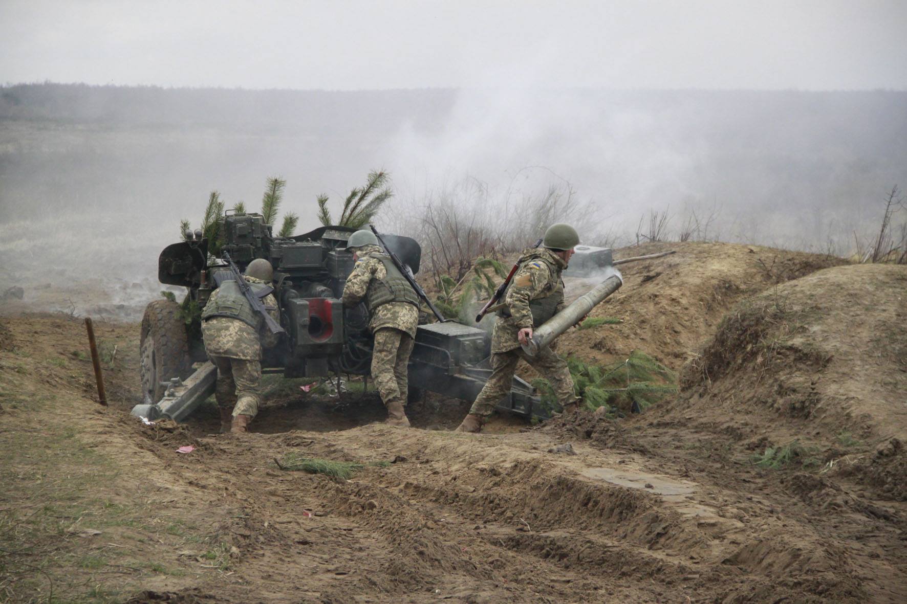
GUN

The primary justification for a smoothbore gun is that the nature of barrel wear with a smoothbore barrel is more conducive to a high pressure, high velocity gun. In both cases, the extent of throat erosion is the primary factor that determines the condition of the barrel, but the nature of throat erosion differs. This is due to the fact that the limiting wear for a smoothbore barrel is the thickness of the eroded bore diameter, whereas for a rifled gun, the limiting wear is the longitudinal length of the throat, because the delayed engagement with the rifling lands severely impacts the dispersion characteristics of the ammunition. The limiting type of erosion is shown in the drawing below, taken from the 2004 textbook "Учебник Сержанта Танковых Войск". The throat erodes at a much higher rate than the rest of the bore (excluding the muzzle) regardless of whether the barrel is rifled or not, and in both cases, the throat diameter progressively expands along a certain length due to erosion, but the progression of the eroded length is much faster than the progression of the eroded thickness. For instance, if a given ammunition is capable of eroding a certain thickness from the surface of the throat, then the throat diameter will expand at a nominal rate, with the rate decreasing towards the muzzle end, but the length of the throat affected by erosion can be very long, since the projectile and propellant gasses act on the surface for the entire length of the bore. Given this fundamental limitation, ideally, the service life of a barrel should be determined by the eroded diameter.
Because the length of the eroded throat has an overwhelming effect on the precision of a rifled gun, increasing the longevity of the barrel by increasing the resistance of the bore surface against erosion yields less of an improvement. As such, for guns of increased power, the presence of rifling results in the barrel not being able to fulfill its full service life potential. For a smoothbore, the length of the throat affected by erosion is no longer the primary issue, but rather the throat diameter. Because of this, when comparing two identical guns firing the same ammunition that differ only in one being rifled and the other being a smoothbore, the smoothbore will have a longer service life.
It is claimed on some websites that the T-12 was converted to the 115mm U-5TS tank gun, but this is completely untrue. The T-12 and MT-12 were not developed into any new artillery systems that went into service serially; they were effectively dead-end designs.
As with the preceding anti-tank guns, the T-12 has a semi-automatic vertically-sliding breechblock, with a mechanical firing mechanism. The right side of the breech housing is occupied by the spring-actuated breechblock-closing mechanism and the manual opening lever. The mechanism was not changed on the MT-12.

It is stated in the article "«РАПИРА. Как рождалась знаменитая пушка" ("Rapira": How the famous cannon was born) that during testing, the T-12 gun had an issue with incomplete case extraction. After a shot was fired, the case would be ejected weakly and hang from the opened breech, forcing a crew member to manually remove the case before the next round could be loaded. This affected the rate of fire. It turned out that the problem was a relatively high residual pressure in the chamber during ejection, which compressed the steel cases to the chamber walls and increased its static friction. The problem was solved by modifying the recoil buffer to delay the opening of the breech by around 2-3 tenths of a second.
Elevation and traverse was actuated with a pair of handwheels, each connected to worm gears at the gun cradle pintle and the pinion of the elevation rack. The layout and design is essentially the same as in any other modern towed artillery piece.


The mechanical firing mechanism of the gun is actuated with a large lever affixed to the recoil guard. A possible explanation for using a lever rather than a button on the elevation handwheel is so that the gunner's hand will not be shoved back by the gun if it jumps during recoil. As always, a recocking mechanism allows the firing pin striker to be recocked whenever necessary.
As alluded to earlier, there is an attachment point on the trigger lever mechanism for securing a wire cable connecting to the flash protection shutter of the APN-6-40 night sight so that, when the trigger is pulled, the sight is shielded from the muzzle flash.
The mounting system of the T-12 permits the gun to be traversed by 27 degrees to each side, and elevated from a maximum depression angle of -6 degrees to a maximum elevation angle of +20 degrees. On the MT-12, the elevation limits were expanded to span -7 degrees to +21 degrees. It is worth noting that the bore axis of the (M)T-12 is so low that when preparing to fire at elevation angles of more than 15 degrees, a pit must be dug under the gun breech of the gun to a depth of 20-30 cm. Otherwise, the recoil causes the breech face to strike the ground, and the breech block may be unable to fully open. The limited maximum elevation angle, combined with the low velocity of the proprietary 100mm HE-Frag ammunition, severely limited the reach of the (M)T-12 gun to just 8.2 kilometers.

This range of motion - and especially the full traversing arc of 54 degrees - was not any different from the preceding guns, but considering the increased size and power of the 100mm gun, it was very good. With the low bore axis of 800mm, the T-12 and MT-12 can depress the gun low enough that the muzzle touches the ground.


The photo below, provided by a friend of the author, shows a view of the recoil devices on a T-12. It can be seen that the location and layout of the recoil mechanism is typical of all Soviet guns, with a hydropneumatic recoil buffer on the top left of the barrel paired with a single recuperator on the top right. The levers and the spring for the breech opening mechanism can also be seen on the right of the breech housing. The recoil mechanism shares a close similarity with that of the D-48, but it was not interchangeable nonetheless.

As with the D-48 recoil mechanism, the buffer features an air pocket filling 2-3% of its internal volume to serve as its self-regulating mechanism instead of a replenisher. The design of the buffer and recuperator was almost the same as that of the D-48, but the components were not interchangeable. The recoil recuperator holds a slightly larger volume of Steol-M, 3.6-4.0 liters, and it is pressurized to 58 atm.


This solution does not increase the size or complicate the design of the recoil mechanism, but is unsustainable when large braking forces are involved because an air-oil mixture is compressible, so that the braking response can be altered significantly. For this reason, this method was only used for the recoil mechanisms of guns with a caliber up to 100mm, where the buffer has only a relatively small volume of liquid. For the T-12 and MT-12, the buffer contains 5.45 liters of Steol-M, and the braking force (due to the braking force) is limited by the long recoil stroke.
The T-12 and MT-12 both have a normal recoil stroke length of 680mm to 760mm, with a hard stop at 780mm. The minimum stroke length is 675mm. The recoil stroke is a useful illustration of the power of the gun, with its minimum recoil stroke being equal to the maximum limit of the D-44.
The original design of the 125mm D-81T tank gun, the 2A26, also utilized a free air pocket as a self-compensating mechanism, but this was soon abandoned due to unresolvable issues with the uniformity of the braking force at high temperatures, owing to the high power of the gun, its large buffer fluid content (8.45 liters) and its very short recoil stroke of just 270-320mm.
Like preceding guns, the T-12 was equipped with a pneumatic equilibrator located on the right side of the gun. It was of the same design as on the D-48. The photo below, from the Wikimedia Commons, shows the T-12 equilibrator in the same location as its counterpart on a D-48.

On the MT-12, the pneumatic equilibrator was exchanged for a coil spring equilibrator to enhance its ease of use, since the pneumatic type required calibration in various conditions. The large and rather prominent equilibrator is situated on the right of the breech. A spring equilibrator is by far the simplest, most reliable and most user-friendly type, but the drawbacks are their large weight and volume, particularly when they need to support a heavy gun and function over a large gun elevation arc. This is only somewhat ameliorated by the limited elevation arc of the MT-12. Even so, the massive size of the equilibrator springs and its housing undoubtedly contributed to the significant weight gain of the MT-12 over the T-12.


It is a push-type equilibrator, using compression-type coil springs. The additional load of the front-heavy gun acting on the elevation handwheel is relieved by the force exerted by the equilibrator springs pushing on a piston connected to the gun cradle.
For both the T-12 and MT-12, the barrel and breech together weigh 1,337 kg. The recoiling assembly, which includes the barrel, breech and recoil mechanism, weighs a total of 1,420 kg. In total, the T-12 gun assembly is slightly heavier than the D-48 and lighter than the BS-3. According to Shirokorad in "Энциклопедия Отечественной Артиллерии", the T-12 gun assembly differed from the D-48 only in the barrel, and that the entire breech and its mechanisms were identical to the D-48. However, the recoil system was not interchangeable, as the new 100mm cartridge generated more energetic recoil. It is even claimed in some secondary sources that the T-12 barrel was created by simply boring out the D-48 barrel, leaving the walls smooth and adding a muzzle brake. However, the massive differences in construction show that this cannot be the case.

The chamber consists of two cylindrical sections connected by a truncated conical ramp, which accommodates the bottleneck of the 100mm cartridges. The transition from the chamber to the barrel bore is formed by a forcing cone. The forcing cone aligns the projectile with the bore and ensures that a gas seal is formed upon firing. When a cartridge is fired, the overcaliber obturator ring on a projectile is squeezed by the forcing cone until it fits into the 100mm caliber of the bore, whereupon the projectile can be propelled down the barrel. With an APFSDS round loaded, the useful chamber volume (the volume which is filled with propellant) is 9.4 liters. With HEAT or practice shells, it is 8.9 liters. With a HE-Frag shell, it is 8.188 liters. For comparison, the chamber capacity of the BS-3 field gun and D10 tank gun (with AP or HE) is 7.9 liters, while the 105mm L7 or M68 guns have a chamber capacity of 6.6 liters, and the 90mm M36 and M41 guns have a chamber capacity of 4.9 liters.
With a smoothbore barrel, the necessary equilibrium spin is imparted by canted fins. Due to the elimination of stresses incurred by spin, fin-stabilized projectiles can be fired at higher velocities than spin stabilized projectiles, and fin stabilized ammunition generally performs much better in a smoothbore gun than in a rifled one. As such, even though an APFSDS round can be fired from a rifled barrel, a smoothbore could provide optimal internal ballistics.
A smoothbore barrel also improved the performance of HEAT shells by completely eliminating all unecessary projectile spin, and improved the performance of subcaliber AP rounds by accommodating increased propellant pressures and higher velocities without accelerated bore erosion.
The name of the gun, "Rapira", was allegedly chosen owing to the long and thin barrel of the gun resembling a rapier, but even though the barrel is certainly thin, it is not particularly long if the muzzle brake is left out. The total length of the barrel, including the muzzle brake, is 6,300mm, or 63 calibers. The total length of the gun, including the breech assembly, barrel and muzzle brake, is 6,650mm, or 66.5 calibers. For comparison, the barrel and breech assembly of the BS-3 had a total length of 5,960mm inclusive of the muzzle brake, or 5,604mm without the brake, and the barrel alone is 5,350mm long. The (M)T-12 chamber is 915mm long, including the forcing cone. The cartridge case, being 913mm long (less when the rim is excluded), fits almost the entire length of the chamber but leaves a sufficient gap for the obturator ring of the projectile to be pressed against the forcing cone. For all ammunition types, the obturator ring is the copper band affixed just slightly ahead of the cannelures around which the cartridge case is crimped.

Of the total length, the breech has a measured length of 345mm as shown below, and the muzzle brake has a length of around 400mm, estimated based on the drawing above. The barrel is of a monobloc construction with an integral muzzle brake. Excluding the breech and muzzle brake, the barrel alone has a length of around 5,900mm, making the (M)T-12 an L/59 gun, which is considerably longer than the D-48 and BS-3 barrels (5,350mm, L/53.5). However, some of this length comes from the long chamber needed to fit the 100x913mm cartridges, so the difference in shot travel distance inside the barrel is not as large as the barrel length alone suggests. From the known chamber length and the approximate length of the muzzle brake, it can be determined that the bore has a length of around 4,985mm, giving the barrel an effective length that is longer than the rifled length of the BS-3 and D10 barrels (4,630mm) by 355mm, which is considerably smaller than the 550mm difference in gross barrel length. Though there is some uncertainty in the muzzle brake length due to the scaling of the drawing above, it is abundantly clear that the effective length - when judged by the bore length - of the T-12 and MT-12 barrel is only slightly greater than the BS-3 and D10 guns.

Technologically, the gun barrel does not surpass the performance of other artillery barrels of the time, and this can be seen in the fact that the operating pressure of the gun is not particularly high - when firing a standard APFSDS round, exemplified by the 3UBM1 round, the nominal operating pressure of the T-12 and MT-12 is 328.5 MPa (3,350 kgf/sq.cm) under standard conditions with a propellant temperature of 15°C. This is only 11.6% higher than the BS-3 and D10, which have a nominal operating pressure of 294 MPa (3,000 kgf/sq.cm) when firing AP. From all available evidence, it appears that the higher pressure was merely achieved with a heavier propellant charge of 6.85 kg as compared to the 6.5 kg and 6.585 kg charge used in the APFSDS and APDS rounds for the D10 tank gun. The higher muzzle energy of the T-12 gun can be entirely ascribed to the slightly higher pressure and slightly larger weight of propellant. The significantly larger volume of the chamber itself, standing in at 9.4 liters, was not used to pack more propellant, but instead serves to regulate the maximum chamber pressure.
The muzzle of the barrel features an integral perforated brake with 80 holes, divided into pairs of 20 holes on each side. In the textbook "Основи Будови Артилерійських Гармат Та Боєприпасiв" (The Basics of Artillery Guns and Ammunition) by A.Y. Derev'yanchuk, this type of brake is described as an integral chamberless honeycomb muzzle brake. A honeycomb muzzle brake is a type of perforated brake with a large number of symmetric round holes arranged in a honeycomb pattern, and the lack of a chamber refers to the fact that the internal diameter of the muzzle brake is the same as the barrel bore, being an extension of the barrel itself. According to a technical description of the MT-12 from a textbook published by the military faculty of the Saint-Petersburg State University, the brake absorbs around 35% of the recoil force.

This type of brake is easy to manufacture. Perforated muzzle brakes of this type are produced by simply designing the gun barrel with an extended bell, and then drilling holes into it after forging the barrel. It is necessary for such a brake to have thickened walls to create a sufficiently long venting channel and to offset the structural weakening incurred by the perforations in conjunction with the honeycomb pattern of the perforations. Moreover, because the brake is integral to the forged barrel structure, it is innately stronger than non-integral brakes as those tend to have more complex shapes formed by casting and are affixed with threads and secured by pins. Any possibility of a brake malfunction or self-detachment are also eliminated with an integral design. Like the bell on a conventional barrel, the large thickness of the brake walls makes it highly resistant to scratches, dents and mechanical damage in general. The acceptable scratch depth is 24mm, equal to the permissible limit for the base of the barrel.
The brake was used for boresighting by the conventional method of affixing two strings to form a crosshair, then using a boresighting scope to look through the barrel from the breech end. The gunner lays the gun on a reference point in the landscape, then proceeds to adjust the sights until the line of fire coincidences with the line of sight.


Although the common perception is that the presence of a muzzle brake on an artillery piece implies that the blast and dust obscuration is worse compared to one with no muzzle device, it is important to make a distinction between muzzle devices that have a blast deflecting function and those without. Muzzle brakes with baffles function as a blast deflectors, and the deflected blast can considerably degrade crew visibility. Though such brakes divert a portion of the radial muzzle blast to the sides, ostensibly reducing the pressure of the downwards blast, the side blast expands in such a way that more obscurants are raised next to the muzzle which is inconvenient for the gunner, who sits offset to the right or left of the gun.
The perforations are perpendicular to the barrel and are mirrored, so the jets of propellant gas from the holes are not directed back towards the gun crew and the sideways thrust from one side of the brake cancels out the thrust from the other. The fact that the holes are not canted was confirmed by a friend of the author with a practical experiment: passing a pencil through both ends through one of the holes. The photo below, originally shared by sibnarkomat, shows the muzzle blast of a Polish T-12 gun in a live fire exercise.

Recoil reduction is achieved by redirecting a large proportion of the flow of propellant gasses to the sides of the muzzle so that the main forward jet generated after the projectile leaves the brake produces less rearward thrust, and hence, reduces the recoil force. The desired counter-recoil force was provided by having a large number of perforations from which the gasses are redirected. Relative to a brakes that use canted chamber surfaces or angled vents to produce forward thrust in addition, the braking force of this type of perforated brake is limited. As such, it is generally considered to be a medium efficiency brake. It is reported in the document "Gun Blast and Muzzle Brake Symposium" that a similar simple perforated brake achieved a satisfactory efficiency of 40-50% without much increase in blast.

Moreover, in the report "An experimental study of perforated muzzle brakes", it was found that a simple perforated muzzle brake could produce a satisfactory braking effect, attenuate the blast overpressure by weakening the muzzle blast waves, and help suppress muzzle flash. It was even found that the brake was even responsible for a 1.5% increase in muzzle velocity compared to a barrel with no brake, presumably because the integral brake functioned as a modicum of additional barrel length. For an APFSDS round, this is equivalent to around 200 meters of range.
This type of muzzle brake was a natural choice for this type of gun due to the use of saboted subcaliber AP rounds together with HEAT and HE-Frag rounds stabilized by folding fins. The main issue with using overcaliber muzzle brakes together with these types of ammunition is its influence on the separation mechanics of saboted projectiles or projectiles with unfolding fins. Alternatives to a perforated brake include the multi-baffle design used on the 100mm U-8TS gun on the T-62A and the 122mm M62-T2 gun on the T-10M. Those brakes were not integral, but they were chamberless. The influence of the muzzle blast on the projectile after it leaves the muzzle is minimal, but still a valid concern as it may contribute around 6.7% to the dispersion of APFSDS shots due to their fixed fins, unlike folding-fin projectiles which only fully unfold their fins once they are mostly clear of the muzzle blast.
In the article "Gun Blast" by Edward M. Schmidt from the Ballistic Research Laboratory (BRL), published in the "Army R, D & A" journal, Volume 20, Issue 4, the relatively minor effects of a modified muzzle blast from a muzzle brake are explained:
Gas velocities within the propellant gas jet can reach values up to three times the launch velocity of the projectile. Thus, the round is exposed to a high speed flow from the rear, that is, it is effectively in reverse flight. Fin-stabilized projectiles are obviously unstable in such a flow, so BRL has conducted a study of the muzzle blast induced perturbations to the trajectory of a variety of finners.The study showed that for a typical tank gun kinetic energy projectile, if the round to round dispersion produced a spread of impacts on target of 0.3 metres at a certain range, only 0.02 metres of the spread could be attributed to muzzle blast induced perturbations. Major contributions to dispersion were related to in-bore and separation mechanics.
In principle, a perforated brake of the type used on the T-12 and MT-12 guns does not enhance the muzzle blast acting on the tail of an exiting projectile, but rather reduces it because the gasses exiting the side holes are expelled as high velocity jets, unlike baffled brakes which produce side blasts.


For comparison, the much heavier BS-3 gun had a maximum rate of fire (without aiming corrections) is 8-10 rounds per minute, which is quite acceptable, but the aimed rate of fire was just 4-5 rounds per minute. According to A. V. Shirokorad, the low practical rate of fire was because the gun jumped a lot with every shot, which endangered the gunner if he did not move away and could even even shake the sights loose. Though the (M)T-12 can also jump violently if fired without being properly dug in beforehand, it was evidently a more stable system than the BS-3 despite being much lighter.
AMMUNITION

Naturally, the standard ammunition load for the T-12 and MT-12 was heavily focused on anti-armour work. The MT-LB prime mover of each gun would carry 20 rounds internally for immediate use. Of that, there would be 10 APFSDS rounds, 6 HEAT rounds and 4 HE-Frag rounds. The small allotment of HE-Frag rounds were to be used when fighting troop carriers and dismounted infantry accompanying the enemy tanks. Ammunition carriers would be used to reinforce the ammunition stockpiles of a long-term prepared defensive position and to resupply gun batteries. A standard unit of fire consisted of 80 rounds divided into the same ratio of 50% APFSDS, 30% HEAT and 20% HE-Frag. Needless to say, preparation of a unit of fire for a single T-12 or MT-12 gun battery was a more challenging logistics task than for 85mm guns.
The maximum tabular firing ranges of the ammunition and their corresponding firing elevation angles are as follows:
APFSDS - 3,000 meters (+0.4 degrees)HEAT - 6,000 meters (+20 degrees)HE-FRAG - 8,200 meters (+20.18 degrees)
It is important to note that in the case of APFSDS and HEAT, the maximum ranges were significantly greater than the tabular ranges, but as they were not represented in the firing tables, it was not possible to conduct aimed fire at their maximum ranges even with the S71 mechanical sight.
It is also worth noting that in U.S Army documents detailing enemy weapons and their capabilities, it was noted that if an MT-12 had its trails dug in to provide 45-degree elevation, the maximum range with HE-Frag is extended to 16,000 to 21,000 meters. Additional information on this capability is lacking, but the lack of firing tables for an elevation angle exceeding the maximum tabular angle of +20.18 degrees seems to indicate otherwise.
In terms of dimensions, 100x913mm ammunition significantly exceeded all other unitary cartridges for artillery in the Soviet Army at the time. The length of a HE shell is 1,284mm, which would have been totally unacceptable if the T-12 was mounted in an enclosed armoured vehicle.
4G8 steel cases with a KV-5-U primer are used for all ammunition types. The case has a rim diameter of 147mm and a mouth diameter of 100mm, identical to the D-412 steel case in the 100x695mm caliber used by the BS-3 field gun and D10 tank gun series. However, 4G8 is much longer, having an overall length of 913mm. 4G8 cases weigh 8.1 kg, which is rather counterintuitive given that the much shorter D-412 steel case weighs 8.50 kg.


The length of the case was greatly lengthened with a long, pronounced neck to accommodate the stabilizer fins of the entire range of fin-stabilized ammunition. However, though this may have been a serious issue were the gun mounted in a tank or an enclosed self-propelled tank destroyer, the enormous cartridge length was inconsequential for the T-12 and MT-12.
The rim and base diameter of the case is the same as the cases for the 85mm D-48, 100mm BS-3 and 122mm howitzers. This is a significant detail, because it meant that the same dies built to manufacture existing artillery ammunition could also be used to manufacture the new 100mm cartridge case. The process would only differ in that the case had to be drawn more times through the die to produce the required case length and wall thickness.
Although the rim diameter is the same between the 4G8 and the D-412, the 4G8 case was not merely a D-412 case with an elongated neck. The tapered section of the neck is much shorter, the body of the case is longer, and the walls were thinner. Even if the long neck is excluded, the capacity of the 4G8 case is substantially larger than the D-412 owing to its length.
Minor variations of the 4G8 were used for different ammunition types. The 4G8-1 case was used for APFSDS rounds, whereas the 4G8A case was used for HE-Frag and HEAT rounds that were affixed with a single crimp.
PROPELLANT
Nitrodiglycol propellant was used for all 100mm ammunition. Propellant sticks were used rather than grains, with two bundles stacked together, separated by a cardboard ring. A flame arrester in the form of a ring-shaped bag with 8/1UG powder is attached to the primer, and a lead wire is packed into the case as a decoppering agent to prevent copper fouling in the barrel bore surfaces, made necessary by the continued use of copper driving bands.
According to "Chemistry and Technology of Explosives Volume III", using nitrodiglycol as an alternative to nitroglycerine provides a number of benefits in terms of nitrocellulose solubility and stability, as well as ease of manufacture. In terms of internal ballistics, the use of nitrodiglycol serves mainly to greatly reduce the calorific value of the propellant, reduce the heat of combustion and thus markedly reduce bore erosion without degrading the pressure characteristics. This, combined with the lack of rifling, would have made the T-12 a highly economical field gun. The use of nitrodiglycol also served as a flash suppressant.
The propellant charges for all 100mm ammunition lack a primer tube because it was not necessary for a uniform burn. Propellant in the form of long sticks gives a very uniform burn when ignited with a base primer, because the hollow channels inside and between the sticks permit the flame from the primer to travel the entire length of the charge and thus ignite propellant evenly along the axis of the charge.
APFSDS

In accordance with the Soviet preference for KE ammunition in high performance guns, APFSDS ammunition was the primary anti-tank round for the T-12. Similar ammunition was also being developed abroad during the 1950's, but did not enter service despite the recognition of their various merits. The USSR took the first step, making the T-12 became the first artillery piece in the world to be armed with APFSDS ammunition. The roots of this ammunition in the USSR lay in the research work for expanding the reach of anti-aircraft artillery, carried out by Chief Ballistician V. V. Yavorskiy of the NII-24 research and machine-building institute (NIMI). By a resolution of the Council of Ministers of the USSR in November 1952, NIMI was assigned with task of creating fin-stabilized subcaliber ammunition for smoothbore anti-aircraft artillery, and in 1956, the responsibilities of NIMI were greatly expanded as it was declared as the sole authority for designing and mass producing artillery ammunition for the Soviet military by government decree, and the Pavlograd artillery range was handed over to the institute. In this capacity, Chief Ballistician Yavorskiy applied the work on subcaliber ammunition to anti-tank artillery, resulting in the creation of APFSDS ammunition for the T-12 and the subsequent adaptation of the same projectiles for the 115mm 2A20 (U-5TS) tank gun. The success of the 2A20 and the creation of the 125mm 2A26 gun for the T-64A irreversibly solidified the role of APFSDS ammunition in the Soviet Army.
Sticks of DG-4 15/1 propellant was used in APFSDS ammunition up to the 3UBM10 "Kalach" round. It is a nitroglycolic powder. According to the classification index for this type of powder, DG-4 has a calorific value of 820 kCal/kg. For comparison, the triple-base M30 propellant used in a 105mm APDS and HEAT rounds has a much higher calorific value of 950 kCal/kg. The APFSDS ammunition for the 115mm U-5TS tank gun also uses DG-4 propellant, but other domestic APFSDS ammunition was filled with different propellants of various types. Additionally, 100mm APFSDS had a wax paper phlegmatizer liner to reduce barrel wear.
According to the manual for the MT-12, the standard 3BM1 and 3BM2 were considered enough to defeat the frontal armour of medium tanks from up to 2,000 meters and heavy tanks from up to 1,000 meters. A characteristic feature of 100mm APFSDS ammunition was its extraordinarily high velocity. They were the speediest ammunition to see service anywhere in the world for a brief period, until they were surpassed by 115mm APFSDS. It is stated that the flatness of the trajectory at long ranges and the short flight time made it possible to use them to engage highly mobile targets (light tanks, armored personnel carriers, automobiles, etc.) at ranges of up to 3,000 meters. The side armour of any tank would also be vulnerable at such distances, so a tank moving side to side was also a viable target.
Moreover, the firing tables show that influence of wind on the trajectory of these high velocity APFSDS rounds was practically negligible, which absolved the simplicity of the (M)T-12 fire control system. The angular correction required for a 10 m/s crosswind reached only 0.9 mils when firing at 3 km, whereas a 3BK3 HEAT round would require a correction of 10.2 mils at the same distance. At typical combat ranges of up to 2 km, the needed corrections are small enough to be ignored, allowing gunners to simply point and fire. This contributes to a higher rate of fire. In combat, one of the only reasons to choose HEAT over APFSDS is that it was forbidden to fire APFSDS rounds when there are friendly troops in front of the firing line within a range of 1,000 meters and in an arc of ±5 degrees, due to the danger posed by the discarded sabot petals.
Due to the relatively static nature of anti-tank gun deployment, allowing the creation of range reference points and kill zones, the first hit probability of a T-12 or MT-12 is inherently quite high. The high precision of the gun contributed to this, and the hit probability on both static and moving targets was additionally augmented by the high velocity and flat trajectory of its APFSDS ammunition.
When the T-12 entered service, it was supplied with a steel long rod penetrator round and a cored penetrator round. The former was better suited for highly oblique armour plate, while the latter was best on flat or near-flat armour. These two types of subcaliber penetrator formed the basis of Soviet APFSDS ammunition technology for the next two decades, and managed to remain relevant throughout this time despite their simplicity due to a rather fortuitous onset of stagnation in the development of tanks in the West tied to the collapse of the MBT-70 (KPz-70) project.
Throughout the service life of the T-12 and MT-12 guns in the Soviet Army, the troops equipped with these guns only received one new model of APFSDS ammunition, the 3BM24 "Kalach" round with enhanced penetration. The new round did not fundamentally change the capabilities of the gun. It merely improved the probability of kill against existing NATO tanks to varying degrees.
In the mid to late 1980's, the MT-12 could still be considered reasonably effective for their role thanks to the introduction of a new APFSDS round with a long rod DU penetrator, which broadly matched the capabilities of contemporary 105mm APFSDS and permitted the otherwise obsolete MT-12 to defeat the frontal armour of the M1 Abrams and Leopard 2, as these tanks were only armoured against older threats.
PRECISION
The T-12 and MT-12 are allegedly considered to be extremely accurate guns by Soviet and modern Russian and Ukrainian artillerymen, earning it the moniker of "sniper artillery". However, the evidence suggests that technically, while it is indeed a highly precise gun, especially relative to conventional artillery, its performance is good, but not extraordinarily good by the standards of tank guns.
According to a technical manual for the medium repairs of the MT-12, when zeroing in the gun at 100 meters, APFSDS ammunition is to be used and all holes in the shot group must be within a 130mm square. If the distance between the holes that are furthest apart is measured to be greater than 130mm, then the group should be considered uncountable and abnormal. In terms of angular size, this is equal to a maximum angular dispersion of 1.3 mils.
The manual also states that the mean shot dispersion in the horizontal and vertical planes, which is measured as the dimensions of the area where 50% of the shots land, does not exceed 30cm when shooting at 1,000 meters or no more than 25mm when shooting at 100 meters. This translates to an angular dispersion of 0.25 mils at 100 meters, widening to 0.30 mils at 1,000 meters. This is also corroborated by a Ukrainian firing table for the 3BM1, 3BM2 and 3BM24 rounds, which also states that the mean dispersion at 2,000 meters is 0.5 meters in both planes.
From this, it can be said that the precision of the T-12 and MT-12 is equivalent to a D10 tank gun firing 3BM8 APDS and is also equivalent or better than foreign guns firing subcaliber ammunition, particularly 105mm guns.
For comparison, it is stated in the report "Performance of Chrome-Plated 105mm M68 Gun Tubes with Discarding Sabot Ammunition" that the data accumulated from 563 acceptance tests of M392A2 rounds showed horizontal and vertical standard deviation dispersions of 0.30 and 0.33 mils respectively, for a CEP circle of 0.37 mils. CEP is equivalent to mean dispersion, both being measurements of the 50% dispersion zone of shots. However, guns like the 115mm U-5TS and 125mm 2A26 had better precision. 115mm APFSDS ammunition in particular was highly precise, having a mean dispersion of 0.18 mils in the horizontal plane and 0.23 mils in the vertical plane.
3UBM1
3BM1

As the name indicates, 3UBM1 was the first subcaliber round to be classified in the GRAU index, established in 1956. It allegedly entered service in 1960. An almost completely identical design was used for the slightly larger 3BM3 projectile of the 3UBM3 round, the third APFSDS round to be indexed and the third to be put into service in the Soviet Army. The design of the penetrator is fundamentally quite simple - it essentially a greatly elongated APCR round.
Its high muzzle velocity of 1,575 m/s provided for an exceptionally flat trajectory compared to all other available munitions at the time with the sole exception of the 115mm gun of the T-62, as that had an even greater muzzle velocity. With a point blank range of 1,880 meters, 2,130 meters and 2,230 meters against a target with a height of 2.0 meters, 2.7 meters and 3.0 meters respectively, the 3BM1 round allowed a T-12 or MT-12 gun crew to confidently engage tank-sized targets at any practical combat range during an engagement even when relying purely on battlesight gunnery techniques, without needing a rangefinder of any kind. The firing table shown below, digitized by Aleksandr Mandadzhiev, is a firing table for both 3BM1 and 3BM2, as they are considered to be ballistically equivalent.

According to the firing tables for the 3BM1, 3BM2 (and 3BM24) rounds, the rate of speed loss is 125 m/s per kilometer of travel (in standard conditions). According to V.A Grigoryan in "Защита танков", the 115mm 3BM3 projectile has a rate of speed loss of up to 128.5 m/s per kilometer. Given the close design similarities, it is unsurprising that the 3BM1 projectile decelerates at almost the same rate, and both suffer from higher deceleration than APDS rounds due to higher drag. For comparison, APDS ammunition in the 100mm and 105mm calibers decelerate at a rate of around 100 m/s per kilometer.
The photo below, from the user vityz3819 of the guns.ru forum, show the projectile assembly separated from the case and its propellant. The projectile assembly includes the sabot. Considering that the weight of the projectile assembly is 4.3 kg while the in-flight projectile alone weighs 3.38 kg, it can be determined that the sabot weighs 0.92 kg.

To withstand the stresses of launch, the sabot and the bore-riding stabilizer fins on the projectile were made from 40KhFA chrome vanadium steel, a type of high-speed steel normally used for steel cutting tools. The fins have canted surfaces designed to impart a spin of 800-1,000 rotations per minute.

The penetrator assembly consists of the steel body of the projectile, which is a rod with a uniform diameter, and an armour-piercing cap screwed onto the steel body that would be covered with a ballistic cap. The armour-piercing cap was affixed with epoxy resin. The tail of the projectile is fitted with a 6-bladed stabilizer fin assembly.
35KhZNM tool steel is used for the steel projectile body. It is a impact-resistant steel with particularly high toughness as well as high strength and resistance to fatigue fracture. 35KhZNM steel used for APFSDS penetrators was rated for a Brinell impression diameter of 2.6-2.8mm along the nose of the penetrator. This translates to a lower boundary hardness of 477 BHN and an upper boundary hardness of 555 BHN.
The armour-piercing cap has a length (thickness) of 0.52 calibers, or 22mm. The armour piercing cap has a hollow cavity that accommodates a small tungsten carbide core weighing 0.45 kg, and its nose is blunt to facilitate the penetration of sloped armour. The cap also protects the core from shattering upon impact. The core is 56mm in length and has a diameter of 32.5 mm. Cores were machined with a 16mm socket to allow it to be fitted onto the steel body of the projectile, then secured with epoxy resin.
The steel body provides energy to the penetrating core by the conservation of momentum, similar to old APCR ammunition. Because the projectile body is a subcaliber assembly that does not exceed the diameter of the tungsten carbide core, it maintains contact with the core throughout the entire depth of its penetration path in armour, unlike APCR projectiles with a full caliber body, which are inevitably stopped by the armour.
According to the munitions design textbook "Устройство и действие боеприпасов артиллерии", the armour perforation limit of a cored APFSDS shot can be approximated by the Jacob deMarre formula for nickel steel armour, taking coefficient 'K' to be 2,800 and using the diameter (42mm) and weight (3.38 kg) of the full projectile for the variables 'D' and 'Q' respectively, or their equivalents in whatever notation variant is used. It is important that the full projectile weight is used rather than the penetrator alone, because the kinetic energy of the stabilizer fins is transferred to the penetrator by momentum transfer until the very end of the penetration when the fins themselves impact the surface of the armour. This is possible because the tungsten carbide core causes the projectile to behave approximately as a rigid body penetrator rather than an eroding penetrator.
It is noted in the textbook that initial reference values for the armour penetration of the round must be determined on experimental firing. In the absence of such data, the known performance of 3BM3 (an identical penetrator design) must be used instead. By normalizing its known penetration with the deMarre formula, it can be observed the thickness exponent should be modified from 1.4 to 1.34.
Using the normalized deMarre formula, the following results are obtained:
| Range (m) | Muzzle | 1,000 | 2,000 |
|---|---|---|---|
| Penetration at 0 degrees | 288mm | 253mm | 223mm |
| Penetration at 30 degrees | 233mm (269mm LOS) | 204mm (235mm LOS) | 180mm (207mm LOS) |
| Penetration at 60 degrees | 102mm (204mm LOS) | 90mm (180mm LOS) | 79mm (158mm LOS) |
It is stated in the textbook that cored APFSDS penetrators have somewhat higher penetration than monobloc steel long rods at an armour obliquity of up to 30 degrees, but have less penetration at an obliquity of 60 degrees and greater.
Aside from its penetration power in RHA, it is also important to note that RHA was not the most common type of steel armour on the modern tanks of the time. On the M47, M48, M60, M60A1, AMX-30, Centurion and Chieftain tanks, rolled plates could be encountered only sparingly on the main armoured surfaces, i.e. the turret and hull frontal arcs. The only tanks to use rolled steel armour for major assemblies were the Centurion and Leopard 1 which had their hulls assembled entirely from rolled plates.
However, low hardness steel, particularly low hardness cast steel, is exceptionally poor against subcaliber penetrators of all types. Conversely, high hardness armour has an extremely positive influence on resisting subcaliber penetrators. Soviet research into the effect of armour hardness on cored 115mm APFSDS (3BM3) showed that a 100mm high hardness steel plate set at an angle of 70 degrees had the same penetration channel depth as a 120mm medium hardness steel plate at the same angle, giving a higher mass and thickness efficiency by 23%.

Moreover, tests with 57mm subcaliber simulants with a tungsten carbide core with a diameter of 19.3 mm at a muzzle velocity of 1,400-1,450 m/s showed that, when the impact angle is 0-40 degrees, high-hardness armour has a 16-25% mass efficiency advantage compared with medium hardness armour. The difference narrows to 10% when the impact angle increases to 70 degrees, but even so, the disadvantage of lowering the hardness is abundantly clear. It can be surmised that the low hardness of 210 BHN on tanks like the M48 and M60 greatly improved the effectiveness of 3BM1, even ignoring the lower resistance of cast steel compared to rolled plates.
3UBM2
3BM2

As the cheaper alternative to 3BM1, it was the twin of the 115mm 3BM4 projectile which was its derivative. 3BM2 lacks a tungsten carbide core. It features only a steel penetrator with a steel armour-piercing cap. When fired, the nominal maximum operating pressure is 328.5 MPa (3,350 kgf/sq.cm). Its muzzle velocity of 1,575 m/s was equal to that of the 3BM1 projectile. 3BM2 is considered to be ballistically matched with 3BM1.
It was noted in the report "Development of 90mm Shot (Armor Piercing). Fin-Stabilized Discarding Sabot for the Defeat of Armor" that the (steel) APFSDS projectile created from the project had very low costs compared to HEAT and especially compared to APDS. Each APFSDS projectile cost only $25, compared to $40 for a HEAT shell and $125 for an APDS projectile.
Being a close analogue to such ammunition, Soviet steel APFSDS ammunition would have shared the same low manufacturing cost. The highly economical nature of solid steel penetrators would have made such ammunition deeply attractive for any large army, and particularly for the Soviet Army given its immense size and the expected ammunition consumption rate of such an army in a major war.
Unlike the steel body of the 3BM1 projectile, the steel penetrator of 3BM2 was made from 60KhNM tool steel. 60KhNM steel features high strength and toughness with a high hardness, rated for a Brinell impression diameter of 2.4mm to 2.58mm along the nose of the penetrator. This translates to a lower boundary hardness of 560 BHN and a upper boundary hardness of 653 BHN. At the tail, which only interacts with an armour plate at the very end of the penetration process, the rated impression diameter is 3.0mm to 3.3mm, or a hardness of 340-414 BHN. The armor-piercing tip is made of 35KhGSA steel. It is a high quality structural steel with a medium hardness of 388-444 BHN; much softer than the tip of the steel projectile body. It was attached to the steel penetrator by soldering.


The length of the full projectile is 525mm and its maximum diameter is 38mm. Its tail is of a much smaller diameter than the nose due to the taper of the penetrator, lowering the average penetrator diameter to 31-32mm. As the No. 11 tracer is standardized among subcaliber projectiles, its diameter of 20mm can be used to ascertain that the penetrator tail has a diameter of just over 20mm. The No. 11 tracer also has a known length of 30.5mm, not inclusive of the built-in cavity behind the tracer compound (an additional centimeter), while the ballistic cap has a length of 35mm as measured from the tip of the armour-piercing cap. After subtracting the ballistic cap and the tracer, it can be estimated that the steel penetrator and its armour-piercing cap have a total length of 470mm. The armour-piercing cap has a length (thickness) of 0.58 calibers, or 22mm. The aspect ratio of the penetrator based on its maximum diameter is 12.4, which qualifies 3BM2 as a bona fide long rod penetrator.

The weight of the full projectile is 3.38 kg, including the components that do not contribute to penetration such as the tracer and stabilizer fins. The weight of the stabilizer fin assembly is unknown, but based on the known weight of 3BM4 stabilizer fins, it can be estimated to have a proportional weight of 15%. For the 3BM2 projectile, this means that it weighs 0.507 kg, and indicates that the penetrator alone has a weight of 2.87 kg.
Thanks to the low weight of the steel "ring" type sabot, its parasitic effect on the effective muzzle energy of the 3BM2 round was limited. It is not entirely clear if the sabot for 3BM2 was interchangeable with the sabot for 3BM1, though they appear identical. Though the maximum diameter of the two projectiles is different, that is largely due to the bulbous cap on the 3BM1 projectile. It seems that interchangeability is likely.

As mentioned previously, penetration values quoted for the T-12 and MT-12 guns universally refer to 3BM2. The tables below detail its performance from 500-3,000 meters, at armour obliquities of 0 to 60 degrees. The penetration channel has a larger diameter than the steel penetrator rod itself.


It can be seen that the behaviour of 3BM2 is completely consistent with a long rod penetrator, having a better penetration capability as the armour obliquity increases from 0 degrees, although this ceases to be true at 2,500 meters and further. Furthermore, it significantly surpasses 3BM1 in penetration at a 60-degree obliquity at all ranges, but conversely, is inferior on flat and modestly sloped armour. This is fully consistent with the information from the textbook "Устройство и действие боеприпасов артиллерии" that cored APFSDS penetrators have somewhat higher penetration than monobloc steel long rods at an armour obliquity of up to 30 degrees, but have less penetration at an obliquity of 60 degrees and greater.
According to calculations using the Lanz-Odermatt perforation formula, 3BM2 should be expected to achieve initial perforation on an additional inch to an inch and a half of thickness. That is, the calculated perforation limit at 500 meters at 0 degrees is 245mm rather than 230mm, and it is 142mm at 60 degrees rather than 125mm. At 1,000 meters, the perforation limit is 225mm at 0 degrees rather than 200mm, and the limit is 131mm at 60 degrees rather than 115mm.
It is important to note that this is true for all Soviet steel long rod penetrators, and appears to indicate that the rated penetration figures are according to the guaranteed perforation criteria rather than initial perforation.
Domestically, the 115mm 3BMU4 round with the 3BM4 projectile is the closest counterpart to 3BM2. The penetrator was significantly heavier (by 18%) and was fired at a higher velocity, but was otherwise equivalent in design. The penetration of 3BM4 at a distance of 1 km is rated as 250mm RHA on a flat plate and 135mm RHA on a plate sloped at 60 degrees, where its impact velocity would be 1,524 m/s. At 500 meters, the impact velocity of 3BM2 is only 16 m/s less, but with a penetration of 230mm and 125mm on a flat and 60-degree target respectively, it can be clearly seen that its penetration power is greatly affected by the smaller penetrator mass.
Domestically, the 115mm 3BMU4 round with the 3BM4 projectile is the closest counterpart to 3BM2. The penetrator was significantly heavier (by 18%) and was fired at a higher velocity, but was otherwise equivalent in design. The penetration of 3BM4 at a distance of 1 km is rated as 250mm RHA on a flat plate and 135mm RHA on a plate sloped at 60 degrees, where its impact velocity would be 1,524 m/s. At 500 meters, the impact velocity of 3BM2 is only 16 m/s less, but with a penetration of 230mm and 125mm on a flat and 60-degree target respectively, it can be clearly seen that its penetration power is greatly affected by the smaller penetrator mass.
The main attraction of the 3BM2 round was its greatly enhanced penetration power on oblique armour plate owing to its long rod form and its material properties, allowing eroding penetration rather than rigid body penetration as was the case for other existing munitions at the time. Its penetration power on flat armour was only slightly worse than a full caliber steel APCBC round fired from a ballistically equivalent rifled gun with a muzzle velocity of above 1,000 m/s. On oblique plates, particularly plates sloped at 60 degrees and above, 3BM2 was overwhelmingly superior.
This is exemplified by the capabilities of the 100mm D54TS gun. The D54TS fired BR-413D, a 16.1 kg APCBC shell at a muzzle velocity of 1,015 m/s, achieving the following penetration values:
| Range (m) | 1,000 | 2,000 |
|---|---|---|
| Penetration at 0 degrees | 235mm | 200mm |
| Penetration at 60 degrees | 85mm | 75mm |
The main downside was a reduction in the penetrator mass ejected behind armour compared to rigid body shells, because the penetrator body erodes during penetration, but this does not necessarily correspond to a reduction in the total post-perforation effect. Due to the low efficiency of steel, a very large volume of armour material is displaced during penetration which produces characteristically large penetration channels and ensures that a large mass of armour fragments are ejected behind the plate.
Muzzle velocity: 1,575 m/s
Cartridge Mass: 19.34 kg
Projectile Mass (with sabot): 4.3 kg
Subcaliber Projectile Mass: 3.38 kg
With this performance, 3BM2 matched the contemporary 105mm L28 APDS round in sloped armour penetration without the use of any tungsten carbide. Foreign APFSDS ammunition of equivalent capabilities were not being used at the time, but experimental models were available for experimental guns. Equivalent APFSDS ammunition fired from the serial 90mm M3A1 gun at a pressure of 47,000 psi (324 MPa) achieves a muzzle velocity of just 1,310 m/s. A closer equivalent to 3BM2 was the American experimental 90mm T82E22 round fired from the experimental T114 gun. Its 3.22 kg steel penetrator was 12% heavier, but it was launched at a lower velocity of 1,524 m/s. With this, it could achieve the following performance:
3UBM10
Cartridge Mass: 19.34 kg
Projectile Mass (with sabot): 4.3 kg
Subcaliber Projectile Mass: 3.38 kg
With this performance, 3BM2 matched the contemporary 105mm L28 APDS round in sloped armour penetration without the use of any tungsten carbide. Foreign APFSDS ammunition of equivalent capabilities were not being used at the time, but experimental models were available for experimental guns. Equivalent APFSDS ammunition fired from the serial 90mm M3A1 gun at a pressure of 47,000 psi (324 MPa) achieves a muzzle velocity of just 1,310 m/s. A closer equivalent to 3BM2 was the American experimental 90mm T82E22 round fired from the experimental T114 gun. Its 3.22 kg steel penetrator was 12% heavier, but it was launched at a lower velocity of 1,524 m/s. With this, it could achieve the following performance:
4" at 55 degrees (177mm LOS) - V50 of approx. 3,800 ft/s (1,158 m/s)5" at 55 degrees (221mm LOS) - V50 of approx. 4,450 ft/s (1,356 m/s)6" at 55 degrees (265mm LOS) - no V50 obtained; one perforation at 5,000 ft/s (MV)
As would be expected for a steel penetrator, the T82E22 penetrator produced holes that were 4" (100mm) in diameter, much larger than the 40mm diameter of the penetrator itself.
3UBM10
3BM24 "Kalach"

In 1972, a directive to modernize the armour-piercing munitions for anti-tank guns of the 100mm to 125mm calibers was issued. From this, four interlinked research projects were started: "Izomer", "Kalach", "Zastup" and "Zakolka" for 100mm, 115mm and 125mm guns. Owing to the shared developmental background, the 3BM24 "Kalach" projectile shares a near-identical design with its brothers, differing only in scale and the details related with case and gun compatibility. These rounds entered service in 1977-1979, although mass production began in 1975-1976.
3BM24 has a cored penetrator, having a tungsten carbide core in the tip like 3BM1. Instead of the complex core used in 3BM1, 3BM24 contains the standard 0.27 kg VN-8 tungsten carbide core, shared with the 115mm 3BM21, 125mm 3BM22 and 100mm 3BM25 rounds. The core is 20mm in diameter and 71mm in length. Instead of a relatively thin steel cap atop the core, a massive VNZh-90 tungsten alloy armour-piercing cap with a blunt tip is fitted.
The new features increased the weight of the projectile assembly to 4.55 kg, and the weight of the propellant was marginally reduced by 0.05 kg, presumably so as not to exceed the maximum operating pressure of 3BM1 and 3BM2. Because of this, the muzzle velocity of 3BM24 was reduced to 1,548 m/s.
The sabot is assumed to weigh 0.92 kg, identical to the ring sabot of 3BM1 and 3BM2. From this, the weight of the in-flight projectile is calculated to be 3.63 kg.
The projectile is fitted with a slightly modified ring-type sabot with four engagement threads. A new 5-bladed stabilizer fin assembly was implemented, undoubtedly due to the forward shift in the center of gravity due to the heavy tungsten alloy cap. The fins have a longer tip chord which increases their wing area, probably to provide the equivalent lift of the earlier 6-bladed fin design. This explains how the sixth fin was eliminated.
Despite the shortfall of 27 m/s in velocity, which is a considerable loss as it is equal to 200 meters of distance and adds 0.3 meters to the apogee of the flight trajectory, 3BM24 is still considered to be ballistically matched to 3BM1 and 3BM2 in firing tables, and the point blank range on a target with a height of 2 meters is 1,850 meters - only 30 meters short of the preceding rounds. This can be explained by 3BM24 having a more modest rate of velocity loss compared to 3BM1 and 3BM2 owing to a combination of its greater weight, allowing it to better overcome air resistance, and the slightly reduced drag of its new fin design.
Indeed, similar characteristics are found when the 125mm 3BM22 shot is compared to the 3BM15 shot. While the 125mm 3BM15 projectile decelerates at a rate of 132.5 m/s per kilometer, 3BM22 decelerates by 105 m/s per kilometer according to Mikhail Rastopshin in the article "Наши танки в реальной войне обречены?" (Are our tanks doomed in a real war?). This can be expected to be true of 3BM24 as well.

Unfortunately, no penetration data is available. It can only be assumed to be better than 3BM1 on flat targets. Based on the relative performance of 3BM22 and 3BM15, the flat penetration increases by 5% and the penetration on RHA sloped at 60 degrees increases by 13.3%.
Regardless, it is extremely unlikely that 3BM24 was sufficient to deal with the frontal armour of any of the three new NATO main battle tanks emerging in the early 1980's: the Leopard 2, Challenger 1, and even the M1 Abrams, which was the most modestly armoured of the three.
Muzzle Velocity: 1,548 m/s
Cartridge Mass: 19.9 kg
Complete Projectile Mass: 4.55 kg
3UBM10 was the last APFSDS round created for the (M)T-12 before the creation of the 3UBM15 round. As DU ammunition was not authorized for use unless a major war involving the defence of the country broke out, 3UBM10 remains the most advanced type available for use even to this day - a sad state of affairs, to put it mildly.
3UBM15
3BM34 "Val'shchik"

Having been informed of new Western developments in composite armour technology, GRAU set forth new requirements to defeat future tank armour in the mid-70's. In 1977, work began on new APFSDS projectiles to accomplish this. The new ammunition would be based on totally new design concepts in order to avoid the limitations imposed by the previous composite rounds.
This round was allegedly mass-produced but never issued to troops, as DU ammunition was procured only to be stockpiled in case of a major European war. The 125mm "Vant" round shared the same fate.
The large increase in sectional density improved its ability to overcome air resistance, so that despite retaining stabilizer fins with a full-bore wingspan, the rate of velocity loss could be reduced somewhat. According to Mikhail Rastopshin in his article "Уран конструкторам не помог" ("Uranium designs don't help"), the drop in the velocity of 3BM32 at a distance of 2 km is 160 m/s, giving an average velocity loss of 80 m/s per kilometer. For comparison, the 105mm M774 round loses 134 m/s at 2 km, and the 105mm M833 round loses just 107 m/s at 2 km.
Though 3BM32 "Vant" is a heavier round for a larger and more energetic gun, it is proportionately very similar to "Val'shchik". As such, it can be reasonably assumed that "Feller" shares the same rate of velocity loss if not less, as the air resistance would be lower at the reduced ordnance velocity of "Feller".
However, due to the secrecy surrounding the DU ammunition possessed by the Soviet Army, many basic details about "Val'shchik" are still lacking. Its muzzle velocity remains unknown. A conservative estimate is that the muzzle energy of the 3BM24 round is maintained, which implies that "Val'shchik" has a meager muzzle velocity of around 1,425 m/s. From this, it can be estimated that the impact velocity of "Val'shchik" would be 1,345 m/s at 1 km, and 1,265 m/s at 2 km, and so on.
This is based on the assumption that the same weight of the same propellant is used, thus providing no increase in muzzle energy. However, the "Val'shchik" round model photographed by Vasily Fofanov at an arms expo, shown above, clearly has black sticks like the APTs-235P 16/1 high-calorie propellant used in the 125mm 4Zh63 propellant charge. The brown-coloured DG-4 15/1 propellant used in older rounds has a lower calorific value.
The UNTs alloy, known as "Material B", is an alloy of depleted Uranium with nickel and zinc. The use of nickel and zinc in an alloy were typically indicates improved formability, ductility and strength. It also serves to provide corrosion resistance, and indeed, nickel and zinc electroplating was studied as a solution for the corrosion issues of the Staballoy (U-0.75%Ti) penetrator used in XM774. Based on calculations using the known properties of the 3BM32 "Vant" penetrator, the density of "Material B" is 18.2 g/cc. This indicates a somewhat higher alloy content compared to Staballoy which has a slightly higher density of 18.6 g/cc on account of its low titanium content of 0.75%.
Based on available photos of the projectile assembly, the length of "Val'shchik" does not appear to be particularly impressive but it is slightly longer than the 125mm "Vant" round and is more slender, not just overall, but in terms of its shape. In the photo on the left below, it is the second from the left, while the "Vant" projectile is the fourth from the left. The "Val'shchik" penetrator is a uniform cylinder, lacking the characteristic thickened midsection of the "Vant" penetrator where the sabot interface threads are machined. The projectile has a total length of between 518mm and 548mm, judging by its size in relation to 3BM9 (second from right), 3BM15 (first from right) and 3BM25 (first from left). From the myriad of reference projectiles on display, it can be estimated with reasonable certainty that the penetrator rod has a length of around 410mm.


The projectile mass is known to be 3.43 kg, so after subtracting the known mass of the stabilizer fins (0.335 kg) and the standard T-20-1 tracer (0.03 kg), the weight of the penetrator alone is 3.06 kg. Knowing these variables, the perforation limit of "Val'shchik" on RHA steel with a hardness of 270 BHN can be calculated using the Lanz-Odermatt formula.
Muzzle Velocity: Unknown, estimated 1,425 m/s
Complete Projectile Mass: 5.38 kg
Projectile Mass: 3.43 kg
Sabot Mass: 1.95 kg
Stabilizer Fin Assembly Mass: 0.335 kg
Calculated Penetration
At muzzle:350mm at 0 degrees205mm at 60 degrees (410mm LOS)At 1 km:330mm at 0 degrees193mm at 60 degrees (386mm LOS)At 2 km:307mm at 0 degrees180mm at 60 degrees (360mm LOS)
At least in theory, "Val'shchik" is not worse than M774 in a conservative estimate. Relative to the tank rounds appearing in the mid to late 1980's, its performance was modest, but still nominally sufficient to fight tanks such as the M1, M1IP and M1A1 as well as the Leopard 2 and the Challenger 1 within their frontal arcs from any relevant combat range. The toughest target would have been the frontal turret of the Challenger 1, but even so, the hull would be vulnerable out to 2 km or more. The Leopard 2 and M1 Abrams can be threatened on both the hull and turret frontal arcs on the basis of the fact that the reference threat for the M1 was an early form of composite APFSDS from the late 1960's (XM578), a precursor to the M735 with inferior performance, while the reference threat for the Leopard 2 the 105mm DM13 composite APFSDS round, fired from the Rh105 smoothbore gun.
For instance, the armour of the M1 Abrams (represented by BRL-1) could be defeated by XM774 from a range of up to 3 km, possibly up to 4 km, according to results published in the report DEFE 70.88 "Future gun tank development". The XM774 round used for these tests closely resembled the final M774 round that entered serial production, as evidenced by its 26mm diameter penetrator instead of the 28mm diameter penetrator of the early XM774.

HEAT

Though the increased diameter and smooth bore of the T-12 permitted much more powerful HEAT shells to be used compared to the D-44 and D-48, it was no more than a supplement to APFSDS, which was firmly established as the main anti-tank munition. In the brief period before the introduction of the 3UOF3 HE-Frag round, HEAT served as a multipurpose shell for targets not suitable for APFSDS.
As with the D-48, the main purpose of 100mm HEAT rounds were to allow tanks with exceptionally thick armour to be defeated in the event that APFSDS fails or if the stock of APFSDS rounds has been depleted. In the document "Збірник Таблица Стрільбі" (Collection of Firing Tables) from the Sumsy State University and in the technical manual for the MT-12, it is advised that, as a rule, HEAT is to be used from the MT-12 only up to a range of 1,500 meters against moving targets, as firing at longer ranges is less effective due to a decrease in the hit probability. Moreover, HEAT is only to be used if it is impossible to shoot APFSDS. One example of such a circumstance is when friendly troops are advancing in front of the gun within the 10-degree sabot separation arc, as the sabot petals pose a severe danger even to lightly armoured vehicles such as BMPs and BTRs.
Naturally, as fin stabilization was firmly established as the most suitable solution for HEAT ammunition, and given that T-12 was a smoothbore gun, all 100mm HEAT shells were fin stabilized.
For HEAT rounds, single-channel DG-3 13/1 propellant sticks with a length of 290mm are used, packed into bundles. There are numerous indicators that HEAT ammunition was loaded with a propellant charge that traded off muzzle velocity in favour of thinning the thin walls of the projectile, with the positive side effects being the reduced barrel wear and high penetration performance, and negative side effects being the steeper trajectory and poorer hit probability on moving targets. Not only were HEAT cartridges loaded with a reduced charge so as to not fire at the same pressure as APFSDS ammunition, but DG-3 itself is a nitrodiglycolic propellant with a low calorific value of 750 kCal/kg.
Hungarian testing on a T-54 using 3UBK2 HEAT rounds fired from an MT-12 confirmed its ability to confidently defeat the armour of a contemporary medium tank with a powerful post-perforation effect. In one of the shots, the jet perforated the cheek of the turret (at a point where there was more than 200mm of armour), passed through a 25-30cm wooden log representing a crew member, perforated a concrete cartridge simulant in the turret bustle ready rack, and was finally stopped in the turret rear wall.
A translation of the original Hungarian article is available in this link.
3UBK2(M)
3BK3(M)

Entering service in 1961 together with the T-12 gun itself, the 3UBK2 round was the second HEAT cartridge to be categorized under the new GRAU index, following shortly behind the 85m 3UBK1(M) round. The 3BK4 shell for the 115mm U-5TS smoothbore tank gun had the same projectile design, differing only in scale and minor structural details.
Unlike the HEAT shells fired from rifled guns, the fins are not opened by centrifugal moment as the projectile does not spin at all before the fins are deployed. Instead, they are opened by the flow of incoming air acting on their beveled surfaces. A 6-bladed fin assembly with an integral No. 12 tracer was fitted to the shell. The burning time of the No. 12 tracer is at least 5 seconds, permitting observation out to at least 2,700 meters, although the effective range is much shorter.
The shell is propelled with a reduced charge of 4.75 kg of propellant, generating a peak pressure of just 215.7 MPa (2,200 kgf/sq.cm). However, the low weight of the shell gave it a relatively high muzzle velocity of 975 m/s. Because of this, the trajectory of a 3BK3(M) shell was naturally quite flat, despite the restrictions on its energy retention imposed by its light weight and the drag of the stabilizer assembly. With a point blank range of 1,020 meters for a target with a height of 2.0 meters, the trajectory of a 3BK3(M) shell was flat enough to comfortably engage the most modern low-profile NATO tanks of the time from a distance of a kilometer, which makes it feasible for situations other than ambushes at short distances. The point blank ranges are as follows:
For a target height of 2.0 m - 1,020 m
For a target height of 2.7 m - 1,150 m
For a target height of 3.0 m - 1,200 m
These figures are from firing table shown below, digitized by Aleksandr Mandadzhiev.

The focus on lightening can be seen in the design of the shell, with its thin shell casing following the inner taper of the warhead complete with protruding rings for the driving band and obturator ring. For comparison, the 3BK5(M) projectile for the 100mm BS-3 and D10 guns had a thicker shell casing that gave it a significantly larger weight despite sharing many similarities in other aspects. As such, the weight of 3BK3(M) is only 10.07 kg, which is substantially less than the 12.2 kg weight of the 3BK5(M) shell. The reduced mass of the projectile allowed its muzzle velocity to be increased without needing to fire it at a pressure approaching that of APFSDS rounds. A marginal improvement in the point blank range was obtained in this way. This did, however, reduce the sectional density of the projectile and worsened its energy retention at increasing ranges. In practice, however, there was effectively no difference. The flight time of 3BK3(M) to 2 km is 3.2 seconds, identical to 3BK5(M), and its flight time to 3 km is 6.2 seconds, as compared to the 6.0-second flight time of 3BK5(M). When compared to the 105mm OCC F1 (Obus-G) and 105mm M456 rounds, both have inferior long range performance.
Like the fin design of other HEAT shells belonging to the late first generation of postwar designs, the fins are very slightly canted to give the projectile a very slow spin calibrated to function as the equilibrium spin for the projectile and to average out the drag forces from each individual stabilizer fin. This allows the projectile to avoid having increased dispersion from asymmetric forces imparted by irregular fins, perhaps due to differences created by manufacturing tolerances or some external interference on the fins. As the smoothbore barrel does not impart any spin to the projectile, the obligatory equilibrium spin was entirely generated by the stabilizer fins.

The main expense of shaped charge ammunition was the high-precision processing of the liner rather than its material, so the use of a steel liner does not reduce the cost of the shell on its own, but material scarcity during a major war can affect the availability of copper, brass, and other types of metals suitable for shaped charge liners. The shaped charge cone has a steep angle of 28 degrees with an open apex, which is connected to the base detonator. This allows the cone to function as a funnel for the spitback element on the nose fuze.
3BK3(M) was fitted with the GPV-2 piezoelectric point-initiating base-detonating spitback fuse. This type of fuze is extremely quick, but an all-electric piezoelectric fuze would be marginally quicker.
The shaped charge cone in 3BK3 has a diameter of 90mm, which is almost a full three centimeters larger than 85mm HEAT shells and even slightly larger than the 88.4mm shaped charge cone of the M456 shell contrary to the external projectile diameter. Moreover, the greatly elongated warhead body of 3BK3 gave the shaped charge a very large built-in standoff distance of 2.75 CD, whereas M456 has a short standoff distance of just 1.78 CD. The magnitude of the design advantages is such that 3BK3 significantly outperforms M456A1 despite having a steel liner instead of a copper one, and despite using a piezoelectric spitback fuze rather than a purely electric piezoelectric fuze.
Officially, 3BK3 is rated to penetrate 350mm of medium hardness steel armour. This is further corroborated by the penetration data given in the munitions design textbook "Устройство и действие боеприпасов артиллерии", indicating a penetration of 350mm RHA. However, there is a significant difference between the average penetration of the shell and the rated penetration, with the rated penetration being much lower and close to the minimum value obtained during tests, presumably to ensure a meaningful post-perforation effect on tanks and other armoured vehicles.
According to a 1979 Soviet report titled "Выбор Кумулятивных Снарядов Для Испытания Брони" (Selection of Cumulative Shells for the Evaluation of Armour), the average penetration of the BK3 shell in armour plate is 425mm with a maximum of 500mm and a minimum of 338mm. All of the penetration figures represent the performance at both 0 and 60 degrees. Similarly, the 115mm 3BK4M shell is rated with a penetration of 440mm RHA, but the study credited it with an average penetration of 499mm RHA.
The large surplus in penetration power theoretically ensures that all existing tank armour would be strongly overmatched with a residual penetration of nearly up to 200mm when attacking tanks such as the M60A1 and Chieftain. For reference, it is stated in "Comparative Effectiveness of Armor-Defeating Ammunition" that a residual penetrating ability of just 2" (50mm) of armour was necessary for a HEAT shell to be considered effectively lethal.
For the sake of comparison, the average penetration of M456A1 in the same targets was found to be 398mm, and the maximum and minimum penetration were 434mm and 355mm respectively. Considering that foreign data indicates that the average penetration of M456A1 is only 380mm, the advantage of 3BK3 may be even more pronounced.
The high performance of 3BK3(M) can be attributed to a combination of a large built-in standoff distance, a quick-acting piezoelectric fuze, steep cone angle, an explosive filler with a high detonation velocity, and the use of a wave shaper - all features of a modern shaped charge warhead. Despite its ostensibly smaller caliber and its use of a steel liner, the 3BK3 shell had a superior penetration performance compared to the 105mm M456 shell with a copper liner.
With this penetration power, the basic 3BK3 shell with a steel liner was potent enough to handle the thickest armour on any NATO tank until the new generation of tanks, namely the M1 Abrams and Leopard 2, appeared in the early 1980's. There is no real difference in efficacy if the 3BK3M shell is used instead, given that the lower penetration of the 3BK3 shell is already enough. It is possible that the increased armour overmatch from the higher penetration power of the 3BK3M shell can increase the probability of kill due to increased post-perforation effects, but on the other hand, the comparatively lower penetration depth of the steel liner in the 3BK3 shell is accompanied by a wider penetration channel. As such, the post-perforation effect of the 3BK3 shell is not necessarily worse.
Muzzle Velocity: 975 m/s
Muzzle Velocity: 975 m/s
Projectile Length: 637mm
Projectile Mass: 10.072 kg
Explosive Filler Mass: 0.84 kg
Cartridge Weight: 23.056 kg
Penetration in RHA:
350mm at 0 degrees250mm at 30 degrees170mm at 60 degrees
From T-12 manual and Croatian technical manual of ammunition for the T-12
3UBK8(M)
3BK16(M) "Kadet"

The "Kadet" round was created in the early to mid-1970's as part of a broader modernization effort to improve artillery and tank ammunition, initiated in the early 1970's. The research and design work was shared between several parallel projects for a series of ammunition for different gun, leading to the simultaneous introduction of the "Kadet", the "Zmeya" round for the 115mm U-TS tank gun and the "Ikra" round for the 100mm D10 tank gun. Together with the "Kalach" round, the appearance of "Kadet" enhanced the firepower of the (M)T-12 incrementally.
The 3BK16 and 3BK16M projectiles differ only in the material of the shaped charge liner, the former having a steel liner and the latter having a copper liner. According to a technical manual for the 3UBK8(M) round, both versions of the cartridge can be loaded with an OKFOL or A-IX-1 explosive filler. OKFOL is octogen with 5% of wax as a phlegmatizer. The penetration power of shells loaded with OKFOL will be higher, but the variance in penetration - that is, the difference between the maximum and minimum - would also be higher. No guidelines were given on how these different shells would be issued. It appears to be purely subject to the availability of OKFOL, as the Soviet explosives manufacturing industry only began mass producing octogen (HMX) since 1972.
The 3BK16(M) shell was fitted with the V-15 piezoelectric point-initiating base-detonating fuze. Unlike GPV-2, this was a purely electric fuze rather than a piezoelectric spitback fuze. Upon impact with the target, the nose initiator, containing the piezoelectric element, generates a current which is channeled down a funnel in contact with the shaped charge liner, which in turn is connected to the base detonator. To complete the circuit, the other terminal of the piezoelectric element is connected to the shell casing, which contacts the corresponding terminal of the base detonator via its threaded socket. Due to the ommission of a spitback mechanism, the action of the fuze was slightly quickened.
Compared to the 3BK3(M) it replaced, the 3BK16(M) shell had a slightly flatter trajectory, having a greater point blank range of around 150 meters for targets with heights of 2.0-3.0 meters. This was mainly achieved due to the lightening of the projectile by 0.5 kg, allowing its muzzle velocity to be raised. From comparing the firing tables of 3BK16(M) and M456, the point blank distances of M456 do not exceed that of 3BK16(M) by more than 100 meters, despite the muzzle velocity of M456 being higher by 100 m/s and being heavier by 1 kg. For example, against a target with a height of 2.1 meters, M456 has a point blank range of 1,300 meters whereas 3BK16(M) has a point blank range of 1,200 meters. This can be attributed to the differences in the projectile spike tip and fin configuration, evidently in favour of the Soviet design.
The 5-second burning time of the No. 12 tracer permits observation out to at least 3,150 meters.
Instead of using forged steel as was the case for the conical noses of conventional projectiles, the stepped nose of the projectile body is made from cast 50L-I steel. Casting was used as the nose has a complex shape, consisting of a hollow spike tip and a shoulder screwed onto the warhead casing. An improved fragmentation effect can be expected as a side effect to the switch to a cast casing, although published data is absent for 3BK16.
Replacing the conical nose with a stepped casing with a spike tip enabled a reduction in the length of the tail required on a fin-stabilized round. The self-stabilizing effect of this projectile shape, sometimes known as shape stabilization, drastically increased the static stability of the shell and thereby decreased the shot dispersion compared to a projectile with an ogival or conical nose, particularly in the presence of wind or turbulence. This is partly due the fact that a spike tip lengthens the distance between the center of pressure and the center of gravity of the projectile compared to an ogive tip, given an unchanged center of gravity. According to the textbook "Устройство и действие боеприпасов артиллерии", the center of pressure is shifted towards the rear by 6-8% of the total length of the projectile, and given that the center of pressure is behind the center of gravity, this effectively meant that the static margin is significantly increased, which translates to a greater degree of static stability. For a fin-stabilized projectile, this means that the fins exert a larger stabilizing moment at any given angle of attack, and thus, smaller fins are needed, or the fins can be located closer to the center of gravity of the projectile to exert the same stabilizing moment by having a shorter tailboom. Both approaches will reduce the lateral displacement of the shell by wind, and allow the shell to be lightened, thus allowing a higher muzzle velocity to be obtained. Both smaller fins and a shorter tailboom were implemented on the 3BK16(M), as the drawings below show.


However, the primary stabilization mechanism of the spike tip is the interaction of the shock wave formed on its tip (a bow shock) with the surface of the projectile shoulder. The bow shock forms a barrier between the flow of air around the projectile and the flow of air directly around the spike tip and in front of the shoulder of the projectile body. The flow of air in front of the shoulder is stagnant as a result of this separation, and as a result of the shape of the bow shock, this zone acquires a cone shape. Within this cone-shaped stagnant zone, the air is not literally stagnant (motionless), but it primarily moves in a recirculatory manner. This zone is stable and symmetrical with respect to the velocity vector of the projectile. With spikes that are 1.5-2.0 calibers long, the border of the stagnant zone is located at the point of separation of the boundary layer, on the tip of the spike. When the projectile is yawed from external influences, the stagnant zone is shifted asymmetrically with respect to the axis of the projectile. The part of the spike tip located closer to the oncoming flow leaves the stagnant zone and is exposed to the air stream, forming a one-sided shock wave. This shock wave forms at a more acute angle than the symmetric shock wave, such that it touches the shoulder of the projectile body. This is shown on the right half of the drawing below. The air pressure at the contact patch of the shock wave generates a reaction force which acts opposite to the yawing direction of the projectile. This reaction moment thereby acts as a stabilizing moment, and its effect supplements the stabilizing moment of the stabilizer fins.

When an undercut (reverse taper) is present on the shoulder, the total component of the flow force is directed at an angle to the longitudinal axis of the projectile, which increases the moment generated by the righting force and thus the static stability of the projectile.
As such, on top of the higher static margin, the asymmetric reaction mechanism of the spike tip allowed the static stability of the shell to rise drastically in response to disturbances. This made it possible to switch to a more efficient tail assembly with a shorter aluminium tail boom and smaller, shorter fins while having an overall increase in static stability. The lower drag of the smaller fins helps to compensate for the increased drag of the spike tip shape, but overall, these spike-nosed projectiles invariably suffer from higher drag than equivalent projectiles with ogival or conical heads.
The most important design feature on the spike was the tapered shape of the fuze, which was used as the mechanism for eliminating dual flow that would otherwise increase drag. On spike-tipped projectiles, a bow shock forms on the blunt tip and a reattachment shock forms at a point below it. If a purely cylindrical spike was used, then dual flow (delayed attachment of the reattachment shock to the bow shock) can occur at certain velocities. Dual flow is a serious issue as it drastically increases the drag experienced by the projectile, and its formation is inconsistent, which means that the ballistic trajectory of the same ammunition can vary wildly from shot to shot. Needless to say, this would be unacceptable for HEAT shells. To eliminate dual flow at a wide range of velocities, a taper was added to the fuze, as in the case of 3BK16, or added to the spike itself. These measures ensure that the reattachment shock reliably forms at a predetermined point on the spike, and that the angle of the reattachment shock is such that it can quickly reattach to the bow shock, as shown in left half of the drawing below.
A common design feature of foreign spike-tipped shells to eliminate dual flow is a small ring placd a short distance behind the tip of the fuze which ensures the early separation of the reattachment shock, but the solution used by NIMI engineers was somewhat more elegant. Though the shock separation ring was an adequate solution, it ceases to function reliably at lower velocities and major inconsistencies arise in the flight trajectory of the projectile. This resulted in ammunition such as the 105mm M456 round and 120mm DM12 round having a drastically increased angular dispersion once the velocity drops below 660 m/s, corresponding to a range of 2 km. In the case of M456, the angular dispersion at 3,500 meters (0.62 mils) was triple that of its dispersion at 2,000 meters (0.18 mils), while the angular dispersion of DM12 was more than doubled, from 0.23 mils to 0.54 mils. This limited the usefulness of these HEAT rounds as long-range alternatives to KE rounds against heavily armoured targets.
The design of 3BK16(M), as well as other Soviet HEAT rounds developed from the same research project, suffers from increased dispersion only when the projectile is destabilized by the transition from supersonic to subsonic flight. This occurs at 3,400 meters. Crossing the 660 m/s threshold, which occurs at 1,700 meters, has no effect on its dispersion. The dispersion of 3BK16(M) only degrades to 0.6 mils at a range of 4 km, which is the largest distance given in its firing table. For 3BK16(M) to degrade to the same dispersion as M456 at 3.5 km, the distance must exceed 4 km.
Unlike most other projectile designs like the 125mm 3BK18 or the 122mm 3BK9, the shoulder of the 3BK16 casing does not have knurls or "teeth". The prominent knurls on other rounds was needed to ensure the smooth loading of the projectile into the gun chamber by a mechanical powered rammer, which can only push the cartridge along the surface of the chamber where the possibility of the projectile getting stuck against the shoulder of the chamber neck may arise. Such knurls were not needed on the 3BK16 shell as a human loader can insert a projectile while taking care not to scrape the shoulder of the projectile against the chamber walls. For the same reason, the 3BK15 and 3BK17 shells for the human-loaded 115mm U-5TS and 100mm D10 tank guns lacked knurls. Aerodynamically, the behaviour of 3BK16 did not differ from the projectile designs incorporating prominent knurls, as the knurls are too small to have a significant influence.
Unfortunately, no information on the penetration power of any variant of the 3BK16(M) shell can be found in the public domain. It can only be assumed to be at least equal to 3BK3(M) if not slightly better. Based on the drawings available in the technical manual for the ammunition, the shaped charge cone has a diameter of 85mm and it has a built-in standoff of 2.5 calibers. Based on the semi-empirical precision shaped charge penetration graph produced by Walters and Zukas, based on the results of copper shaped charges fired against 320 BHN armour steel, the nominal penetration of 3BK16M should be expected to be no less than 425mm RHA while the penetration of 3BK16 should be around 380mm.
Muzzle Velocity: 1,075 m/s
Cartridge Mass: 23.16 kg
Projectile Mass: 9.5 kg
HE-Frag

The HE-Frag ammunition for the T-12 and MT-12 had a reduced propellant charge of just 3.655 kg, with no full charge option. This was the first time for such a situation to exist since the first domestic anti-tank gun, the 45mm 53-K. The cartridges were loaded with the same DG-3 propellant as in HEAT rounds and were packed in the same manner. From all available information, the HE-Frag rounds should be highly economical in terms of barrel life, not only because the gun lacks rifling, but because of the use of a reduced charge of nitrodiglycol propellant.
A highly unusual feature is the presence of a tracer, permitting trajectory observation. A tracer is normally not incorporated into Soviet HE-Frag shells, even fin-stabilized shells which provide free space in the tail boom. Fire correction with such ammunition was invariably done by merely observing the highly visible explosions on impact (burst on target) around the stationary target, with little consideration for hitting moving vehicles, for which a tracer would be most useful. Other ammunition would be used for that purpose.
For HE ammunition, fin stabilization brings few benefits. There is no practical advantage in a non-rotating shell and the additional drag simply reduces its range, but on the other hand, fin stabilization provides the possibility to increase the aspect ratio of the shell beyond the structural limits imposed by spin stabilization. Normally, a high capacity HE shell does not exceed an aspect ratio of 5. However, most fin-stabilized HE shells do not exceed their spin-stabilized counterparts in aspect ratio.

A large aspect ratio is only feasible for a spin-stabilized shell if the ordnance velocity is high enough to allow a more pointed ogive shape to be implemented, which in turn necessitates thicker casing walls to ensure stabilization. However, this design solution negatively impacts the volume available for the explosive payload and adds casing mass to the shell.

3UOF3
3OF15

Thanks to the use of fin stabilization, the body of the shell was elongated to 5.25 calibers. The effect of this was to increase the explosive payload and enhance the fragmentation effect of the shell by a combination of a more optimal weight ratio of explosives to casing, and the greater length of the shell which slightly increases the altitude of its detonation above ground level. The aspect ratio of 3OF15 is superior to the OF-412 and 3OF32 HE-Frag rounds in service for the BS-3 and D10 guns, both of which had an aspect ratio of 4.9. Detailed dimensions are available in the drawing below, taken from "Projectile and Warhead Identification Guide—Foreign, 1997, NGIC, US".

Due to its small propellant charge, the projectile is launched at a muzzle velocity of just 700 m/s which is somewhat low considering the relatively high operating pressure of the T-12 gun and the high muzzle velocity of its APFSDS and HEAT ammunition. The velocity alone is not unusually low relative to other reduced charge rounds for high-powered field guns, but the maximum range was negatively impacted due to the increased drag from the stabilizer fins. Because of this, 3OF15 had a maximum range of just 8,200 meters, which is achieved with a gun superelevation angle of +336 mils or +20.18 degrees. For comparison, the OF-412 shell fired from a BS-3 field gun at a reduced charge (600 m/s) reaches a maximum range of 10,200 meters when fired from the same gun elevation angle of +20 degrees. The firing table for 3OF15, digitized by Aleksandr Mandadzhiev, is presented below.


The advantage of 3OF15 lay in its larger explosive payload and better filler weight proportion, translating to a combination of a superior HE effect and a much more favourable fragmentation characteristics. The stabilizer fin assembly accounts for 9% of the total weight of the projectile, leaving the weight of the projectile warhead alone to be 15.23 kg, where the warhead casing weighs 12.56 kg, the explosive charge weighs 2.234 kg and the V-429E fuze weighs 0.438 kg. From this, the filler weight proportion is 14.6%, almost high enough to classify 3OF15 as a HE shell under the Soviet definition. Overall, 3OF15 is comparable to a 105mm M1 howitzer shell.
For comparison, the OF-412 shell for the D-10T has a projectile weight of 15.6 kg (casing weight of 13.7 kg) and contains a 1.46 kg TNT explosive charge, meaning that the share of the explosive charge is only 10%, which was good considering its high velocity, but lay on the threshold separating a Frag shell from a HE-Frag shell. Additionally, the 3UOF3 cartridge weighs 29.56 kg, which is marginally less than the 30.2 kg weight of a UOF-412 cartridge despite the 3OF15 shell being heavier.
Muzzle Velocity: 700 m/s
Projectile weight: 16.74 kg
Explosive charge weight: 2.234 kg
3UOF12
3OF35

3OF35 does not differ structurally from 3OF15. It differs only in the switch from TNT to A-IX-2, which led to a substantial enhancement of its destructive power in terms of both its HE effect and fragmentation effect. The incendiary effect of the A-IX-2 compound supplemented the improved lethality of the blast and fragmentation.
The weight of the explosive filler increased to 2.5 kg, despite no changes in the internal volume of the shell. This large improvement was achieved by pressing A-IX-2 rather than casting it, reducing the voids and thereby increasing its bulk density to 1.8 g/cc. This increased the filler weight proportion to 16.4%. This is a considerable improvement, but the effective weight is even larger due to the high explosiveness of A-IX-2. By comparing the Trauzl values, A-IX-2 is 1.86 times more explosive than crystalline TNT (530 ml compared to 285 ml) when used in enclosed casing, which is the most relevant metric for explosive bombs and shells. While a simple comparison of their calorific values shows that A-IX-2 has 1.54 times more heat energy, with a specific heat of explosion of 6.44 MJ/kg compared to a specific heat of explosion of 4.184 MJ/kg for TNT, the amount of explosive heat energy by itself says nothing about the ability of the explosive compound to do work; to transfer its explosive heat energy into the shell casing as kinetic energy. By using explosiveness as a reference point rather than the calorific value alone, a much more meaningful estimation of the blasting and fragmenting capability of an explosive can be made. A higher explosiveness has the effect of increasing energy of the fragments produced from the shell casing, which is also increased due to the higher brisance of A-IX-2.
When comparing the fragmentation mass proportion with a lower limit of 0.25 grams (N0.25) and 0.50 grams (N0.5), the greater brisance of A-IX-2 evidently grants a considerable improvement over TNT. An improvement can also be seen when categorically sorting the mass range of fragments into small, medium and large fragment groups when tested empirically using a cylinder made from different grades of steel. With S-60 steel specifically, the grade used for artillery HE-Frag shells, the improvement in fragmentation performance is particularly large, producing 27.8% and 26.7% more fragments weighing 0.25 grams and 0.50 grams respectively.

The overall mass distribution of fragmentation was thereby considerably improved - the proportion of small fragments increased from 15% to 18%, the proportion of medium fragments increased from 26% to 35%, and that of large fragments decreased from 59% to 47%. In this case, small fragments (µм) were defined as weighing less than 1 gram. Medium fragments (µс) weigh between 1-4 grams, and large fragments (µк) weigh more than 4 grams. With a larger quantity of small and medium fragments, the probability of hitting targets is increased, thus improving the lethality radius. This is also mentioned in a patent where it is stated that, for a shell with an S-60 steel case and a TNT filler, 59% of the total fragments can be expected to have a mass of >4 grams, whereas with A-IX-2 or A-IX-20, only 47% of the total fragments do. Brisance is the critical factor responsible for bursting the casing into finer splinters. Essentially, a larger proportion of the steel case is shattered into smaller and faster fragments, which increases the overall probability of enemy personnel becoming a casualty to the shell strike.

After the casing is burst by the blasting pressure, the high explosiveness of A-IX-2 does its part in creating a strong fragmentation effect by imparting more energy into the fragments by performing more mechanical work, nominally 1.86 times more than TNT. Thanks to these two factors, supplemented by the secondary factor of a larger explosive mass, the lethal area of a shell filled with A-IX-2 is often between 1.5 to 2.0 times larger than the basic shell with a TNT filler.
Muzzle Velocity: 700 m/s
Cartridge Mass: 28.56 kg
Projectile Mass: 16.74 kg
Explosive Charge Mass: 2.538 kg
Explosive Charge Mass: 2.538 kg
YESSS I was hoping you'd make an AT gun article, thank you!
ReplyDeleteLove the article. Shame the 125mm Sprut wasn't pushed into production cos it was so heavy.
ReplyDeleteExcellent - I very much enjoyed that
ReplyDeleteFinally got done reading through this entire article.
ReplyDeleteAnother most informative post about Cold War Soviet AT Guns. A topic I and many others probably never really put much thought into. Looking at it now in proper context, I can see why the Soviets held on to them for so long.
Also impressive how good the guns were for their weight. Extraordinary engineering and design work to develop such light yet powerful guns.
Excellent article! I'd add a bit more info about the gunsights, since I have an original OP4M-40U sight. It is big, heavy, and looks very solid structurally. The clarity of the sight picture is just amazing... Better than anything I've ever seen, inculding a very expensive Nightforce gun scope. The only very minor downside is that the picture is quite yellowish, but I do not think it affects the performance at all. Overall, the OP4M-40U seems like a very high quality product.
ReplyDeleteGreat job! Keep up with these amazing articles. The MT-12R was a very interesting read.
ReplyDeleteIt is interest to note chinesebfirm NORINCO actually developed apdsfs round for 85mm tank gun,to wrmed both t60 amphobous tank and type 62 light tank,a sample round was among the displaynin norincon show room.
ReplyDeleteVery excellent article! Would it be possible to put an addendum in for the MT-12 examining the 3UBK10(M)/23 Kastet guided ammunition?
ReplyDeleteHi, gun-launched ATGMs like the Kastet may be covered in the future in a separate article, which will cover all serial GLATGMs used in the Soviet Union.
DeleteThank you! That will be an extremely fascinating read if you can get around to it. You are doing a superb job with this site, it is without peer for those of us interested in Soviet equipment of the Cold War. Thanks again!
Deletevery Impressive article as always! will be hopeful that you will have an article on old soviet air to air missiles
ReplyDeleteSmall mistake in start of text, 3.7cm Pak L/45 Rheinmetall is wrong, it is 3.7cm Pak L/46 Rheinmetall, gun was L46
ReplyDeleteAre you sure?
DeleteHi Iron Drapes,
ReplyDeleteComment on the 3BM34/3UBM15 DU sabot round. Given that we haven't seen any of these in the Ukraine conflict (that I am aware of), despite both sides using MT-12s heavily, and despite documented use of other presumably "war emergency" ammo -- is it possible that this round was just not heavily produced, for whatever reason? If anyone would have stockpiles it would be the Russian Army, and they have been rushing much older (and much newer) ammo to the frontline, yet I do not recall 3UBM15s being documented.
No depleted uranium ammunition has been used at all, it was, and presumably still is, reserved for a hypothetical WW3.
Delete