
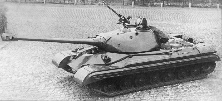
The T-10 heavy tank was formally revealed to the public in its first and only Red Square appearance on the 7th of November, 1957 in the parade for the 40th anniversary of the Great October Socialist Revolution with the T-10 obr. 1956 model representing the series. The parade was held just one month after the successful launch of Sputnik 1, the first artificial satellite to enter low Earth orbit in human history. Among those that made their first appearance on Red Square were the new R-5M mobile strategic nuclear missile on its transporter, the T-54 medium tank, the ZSU-57-2 self-propelled anti-aircraft gun system, and many others, marking this parade as one of the most grandiose political-military displays of the decade as well as one of the most significant from a military intelligence standpoint.
The T-10 was the culmination of over a decade of continuous heavy tank development in the Soviet Union and is the most advanced design of its class to see service in its homeland. It was also arguably the sleekest of all Soviet heavy tank designs, having extremely well-sloped armour on both its hull and turret arranged in a rather pleasing way. As a series, the T-10 boasted a level of technological sophistication that was unmatched in the Soviet Army until the T-64 entered service, and even then, there was significant overlap in the capabilities of the two classes. Soviet armoured doctrine saw the heavy tank as a breakthrough weapon capable of operating independently or alongside other armoured vehicles in mixed tank units that can, by design, eliminate any opposition that a medium tank cannot.
In fact, this was the same general doctrine that dictated the deployment of the M103 heavy tank in the service of the U.S Marines, which made little distinction between heavy and medium tanks in the operational sense. Ken Estes, who is probably the world's foremost expert on the M103 tank series, notes in page 38 of "M103 Heavy Tank: 1950-1974" that "there was no specific doctrine calling for the support of medium tanks in the field by heavy tank units, and in general it was assumed that the specific situation at hand would determine if the heavy tank company would support an infantry regiment in combat, form as part of the division’s antitank plan, or, in the rare case that the tank battalion was used en masse, to operate as part of an armored task force".
The T-10 was organized into heavy tank regiments which would be integrated into a tank division alongside two medium tank regiments. It could also be organized to form heavy tank divisions, but as the purpose of heavy tank divisions on the strategic scale became uncertain in the USSR during the late 1950's, they were eventually declared obsolete, making heavy tank regiments the largest dedicated unit size for heavy tanks.
The development of the T-10 was managed by Zhozef Yakovlevich Kotin, the chief designer of the Chelyabinsk Kirov Plant (ChKZ) design bureau who was previously responsible for the IS-2 and the IS-3, and the design work was handled by chief designer M.F Balzhi who had previously been involved in the design of both the IS-3 and IS-4. The new heavy tank was developed to be the direct successor of the IS-3 (Object 703) and IS-4 (Object 701). Needless to say, an evolutionary progression in tank technology is quite natural, but in this instance, it was prompted by the inadequacies of the first postwar heavy tanks. Problems with the IS-3 emerged shortly after it entered service and it was tentatively supplanted by the IS-4, but the IS-4 itself turned out to be rather flawed and it was discontinued just three years after production began. Conceptually, both of these tanks were designed during WWII and were created under late-war requirements with a late-war engineering school of thought which made them less than adequate for the needs of a postwar USSR.
In the December 2012 edition of the "Отечественные Бронированные Машины 1945-1965" series of articles authored by M.V Pavlov and published in the "Техника И Вооружение" magazine, Pavlov states in page 54 that the IS-4 failed its 1,000 km mobility trial due to the failure of the final drives, destruction of roadwheel and idler wheel bearings, failure of the oil pressure gauges in the engine, premature wear and destruction of the brake pads, failure of the transmission, failure of the hydraulic transmission control mechanism, and more.
Pavlov also mentioned other severe shortcomings of the tank, such as the unacceptably noisy fans of the cooling system. The whistling noise from the pair of radial cooling fans on the engine deck caused such a high amount of acoustic interference that it actually shortened the range of the onboard radio transceivers, and the fans could reportedly be heard from a staggering distance of 7-8 kilometers while the tank was moving. The concentration of carbon monoxide in the tank from the engine and from propellant fumes was also unacceptably high, making it difficult for the crew to operate the tank effectively. To top it all off, the escalation in weight led to one IS-4 costing almost three times as much as an IS-3 without bringing an equal increase in combat effectiveness. Much of this cost was related to the short supply of thick rolled steel armour plates and the difficulties in assembling a tank with such thick armour.
This is all the more unfortunate when earlier on, the initial IS-4 design (Object 701) still had a more modest combat weight of 55 tons in its prototypical form and it exceeded the IS-3 in several technical characteristics including tactical mobility such as having a 25% higher average speed when moving cross-country despite being a heavier tank. Mobility trials confirmed that the IS-3 was quicker and the difference in the mobility between the Object 701 and IS-3 continued to increase as the Object 701 gained more armour in later prototypes. At this stage, the IS-7 was still optimistically projected to weigh just 54-56 tons. In actuality, the pursuit of all-round armour protection would cause the IS-4 to bloat to a combat weight of 60 tons and the IS-7 would weigh a staggering 68 tons. The issues that arose from the weight gain made the IS-4 unsustainable; the mass production of the IS-4 was terminated on the 9th of April 1947. The IS-4M modernization was created with the aim of fixing these issues or at least ameliorating them, but not all IS-4 tanks were modified to this standard by the time the programme was terminated on the 22nd of March 1949.


On the 9th of April 1952, all IS-4 and IS-4M tanks were withdrawn from their frontline stations and relegated to the Reserves of the Supreme High Command (RVGK) - the strategic reserves - and served in this capacity in the Far Eastern Military District. When the Korean War took off, military units stationed in this district including IS-4 tanks were sent to Primorsky Krai (Manchuria) to secure the border between the USSR and North Korea, and when the Sino-Soviet split occurred, IS-4 units stationed in the Far Eastern Military District were mobilized once again and sent to the Transbaikal region bordering China, and the ones stationed in Manchuria were turned towards also China.
In practice, the troubles with the IS-4 meant that the IS-3 was the de facto heavy tank of the Soviet Army despite its own flaws which were being gradually ironed out in new tanks during production and later corrected on existing tanks via an expensive refurbishment programme to become the IS-3M.


The plethora of issues plaguing the IS-4 prompted great skepticism towards the IS-7 as the latter represented an even greater escalation in weight. This had an indirect effect on the eventual rejection of the IS-7 and catalyzed the decision to restrict the weight of all future heavy tanks. On February 18th 1949, the Council of Ministers of the USSR passed resolution No.701-270ss which formally prohibited all further work on heavy tanks with a mass of more than 50 tons. This would allow the crossing of civilian bridges, pontoon bridges, and other tactical bridges for crossing obstacles as these had a weight limit of 50 to 60 tons. It would also allow the heavy tank to be transported piecemeal by rail as the maximum weight capacity set by Soviet railway authority at the time was 55 tons. Attached to resolution No.701-270ss was the order for the LKZ and ChKZ design bureaus to develop a new heavy tank with a weight of 50 tons or less. The Object 730 prototype of the new tank, designed by the ChKZ design bureau with Zhozef Kotin at the helm, was ready for trials just seven months later under the tentative designation of IS-5, not to be confused with the Object 248 prototype from 1944 that was also known as "IS-5".
The IS-5 had a hull design taken directly from the IS-7 but streamlined and trimmed down for reduced weight at the expense of armour protection. Its turret was a completely original design. The IS-5 had the transmission of the IS-4 and used a similar cooling system driven by a pair of large axial cooling fans on the engine deck in the same style as the IS-4, closely patterned after the cooling fans used on the German Panther tank. The image below shows the IS-5 in its 1949 configuration with all of these features.

However, the reliability issues of the IS-4 transmission reemerged on the IS-5. The test report noted the following:
"1. Испытание машины начато 22.09.49 г. за это время она прошла 1012 км, из них:а) проселочная дорога — 501 км;б) пересеченная местность — 511 км.
2. Двигатель проработал 67 ч 36 мин.
3. В процессе испытаний получены следующие средние скорости чистого движения:
а) проселочная дорога 29–27 км/ч;
б) мокрый луг 17,7-16,5 км/ч;
в) болотистый луг (движение осуществлялось преимущественно погружением клиренса), пройдено 314 км 12–14 км/ч.
На отдельных участках сухого пути получали скорость 31–27 км/ч.
4. Основные дефекты:
а) Разрыв и разрушение по швам и целому телу алюминиевых топливных баков после 441 км. Внутренние баки заменены на стальные.
б) Выход из строя обоих бортовых редукторов по причине закручивания и изгиба ведущих валов.
5. В настоящее время машина находится на втором техническом осмотре"
Translated to English:
1. The test of the machine started on 22.9.49 during which it covered 1,012 km, of which:a) Country roads - 501 kmb) Rough terrain - 511 km
2. The engine worked for 67 h 36 min
3. During the test, the following average net speeds were obtained:
a) Country roads 29-27 km/h
b) Wet meadow 17.7-16.5 km/h
c) Marshy meadow (the movement was carried out mainly with sunken clearance), covered 314 km at 12-14 km/h
On some parts of dry roads, the speed was 31-27 km/h.
4. Major defects:
a) Formation of gaps and the destruction at the seams and the whole body of aluminum fuel tanks after 441 km. Internal tanks replaced by steel tanks.
b) The failure of both final drives due to the tightening and bending of the axles.
5. At this time, the machine is undergoing the second technical inspection (author's note: second level of maintenance as part of a planned maintenance schedule).
The main emphasis of the test was that the transmission was unreliable. The tank failed its 2,000 km factory warranty trial due to the failure of the transmission, signalling the need for a new and more robust design. As a result, a new 8-stage planetary transmission was installed in the tank. During the course of the redesign, many other refinements were made to the tank, including the replacement of the fan-based cooling system with a forced-ejection cooling system inspired by the IS-7 project. By the time the tank entered service as the T-10, it combined several of the successful design features of the IS-4 running gear with several features from the IS-7, so it can be said to have an amalgamation of all the best parts of its predecessors in a refined form. At that point, the "Object 730" designation had been applied to three modifications of the same tank under three different names.
Although the T-10 obr. 1953 (right below) was externally similar to the first IS-5 design from April 1949 (left below), the end product had several distinguishing features. The hull underwent minimal modifications, but the turret was given a more rational distribution of armour thicknesses. The armour protection was somewhat increased, and as testing of the tank continued in the mid-1950's, improvements to the casting technology and the distribution of armour mass were continuously made on the production line.


With the less-than-glamorous history of the IS-3 and IS-4 in mind, the T-10 could be rightfully considered the most successful heavy tank to serve in the Soviet Army during peacetime and was unquestionably a good, solid tank worthy of its place, at least by the standards of typical heavy tanks as the T-10 still had all of the drawbacks commonly associated with its class such as high production and maintenance costs and a somewhat low cost effectiveness relative to its actual combat capability. The strategic decision to impose an artificial weight limit of 50 tons undoubtedly had a large influence on the relatively unproblematic career of the T-10.
While the IS-4 primarily served in the reserves and only lasted only a few years in active service, the T-10 saw over a decade of active service in the Western Military District as the backbone of Soviet heavy tank divisions before being slowly withdrawn to the strategic reserves during the tail end of the 1960's, and several heavy tank units equipped with T-10M tanks even continued to serve in the GSFG until the late 1970's. Some sources state that the withdrawal of the last T-10M battalion occurred in 1979.
On the 28th of November 1953, the T-10 officially entered service in the Soviet Army and on the 15th of December 1953, the order was given to put the new heavy tank into mass production under the product code of Object 730. Factory No. 200 was responsible for the manufacture of turrets and hulls. Production of the original T-10 was slow, with only 30 units produced in 1954, 90 units produced in 1955 and 70 units produced in 1956 when the production run ended. Together with the ten pre-production tanks manufactured in 1953 prior to the official induction of the tank into the Soviet Army, the total number of T-10 tanks amounted to only 200 units. This paltry figure was less than a tenth of the total number of IS-3 tanks produced during its own short run and was utterly miniscule compared to the production run of workhorse tanks like the T-54, but even so, even at this early stage the T-10 series already outnumbered the Conqueror of which only 185 examples were built in a longer production run from 1955 to 1959.
However, these T-10 tanks had a number of issues related to the poor quality control of Factory No. 200 for the manufacture of the cast turrets. In 1954, a whopping 50.9% of the turrets of the tanks delivered to the Soviet Army exceeded the design mass of 6,500 kg by the tolerance limit of 5% (325 kg). This improved to 11.5% by 1955, but it was revealed during extensive live fire tests in the same year that 32% of the tested turrets (22 in total) did not meet the design specifications for ballistic resistance. As such, it was recognized that further refinement of the turret design was still needed in order to curb the wastage of resources and ensure that the design criteria for protection could be met consistently. The two photos below show one of the T-10 tanks built in 1954.


On the 17th of May 1956, the T-10A entered service and began production at ChKZ under the product code of Object 731. Although this model officially replaced the T-10 on the production line, there was a transitional period of a few months where both models were being produced simultaneously, with many components being shared by both. Less than one year later, the T-10B entered service on the 11th of February 1957 and began production at ChKZ under the product code of Object 733. Only 110 examples of the T-10B model were delivered when on the 26th of September 1957, the T-10M entered service and fully replaced it on the production line the next year. It had the product code of Object 272. Interestingly enough, the T-10M had a combat weight of 51.5 tons so it exceeded the official weight limit by just a hair, but this was likely considered acceptable as it was still well within the 55-ton railway load limit.
The T-10M obr. 1957 was manufactured simultaneously at both ChTZ and LKZ, but in slightly different forms. The ChTZ factory produced the Object 734 and the LKZ factory produced the Object 272. The two factories produced slightly different models because the ChTZ factory had only recently mastered the production of T-10 hulls when the new Object 272 design from LKZ was adopted as the next primary tank model. Because ChTZ was unable to switch production to the new Object 272 hull rapidly, they had to resort to the compromise solution of mating Object 272 turrets to Object 730 hulls, thus creating the Object 734, known as the Chelyabinsk T-10M as opposed to the original Leningrad T-10M. In 1962, ChTZ was finally prepared to switch to producing Object 272 hulls, so both factories were standardized on the Object 272 specifications. The final modification of the T-10M entered service in 1963 as the T-10M obr. 1963 and the tank continued to be manufactured in this form until 1965.
From 1953 to 1965, a total of 1,439 T-10 tanks and variants thereof were produced in the USSR. The T-10M lasted the longest on the production lines by far and can be considered the definitive representation of the T-10 series, being not only the most advanced model but also the most numerous by a large margin. Although no modernization programmes to bring earlier T-10 models to the T-10M standard were carried out in the USSR, some tanks were retrofitted with night vision equipment to close the gap in capabilities. Some tanks only received a partial modernization as not all parts and facilities were available for the units equipped with T-10 tanks.
To put the production figures of the T-10 into perspective, it can be compared to the M103 and the Conqueror. In 1955, the first Conqueror was built in the Royal Ordnance Factory and production continued until 1959, ending with a total of 185 tanks delivered to the British Army. A total of 20 Mark 1 and 165 Mark 2 Conquerors were built.
The M103 was much more numerous, but the time frame of its deployment was relatively late compared to the T-10. The T43E1 prototype of the M103 heavy tank (it was not designated the M103 yet because it had not been type-classified) entered mass production at approximately the same time as the T-10 but was considered unfit for service in its initial form. The Continental Army Command (CONARC), had finished testing these T43E1 tanks and found them unsatisfactory for issue to the troops as of June 20, 1955. A total of 144 modifications were deemed necessary, but due to the lack of urgency after the conclusion of the Korean War, the Army opted for a simpler refurbishment that applied just 98 of the 144 modifications. The M103 was type classified on the 26th of April 1956 and the first batch of 80 M103 tanks that were modified to the Army standard were operational by the middle of 1957 after troops trials in early 1957 had concluded. By this time, a decade had passed since the production of the IS-3 ceased, the T-10B had already begun mass production and the T-10M was only a year away from replacing it on the production line.
Only around 300 examples were produced, which is barely more than a fifth of the final size of the T-10 fleet. That said, the U.S Army had abandoned all of their heavy tank projects and moved on from the heavy tank concept and had shifted the focus on a main battle tank that could combine the capabilities of a medium tank and a heavy tank in a new and rather forward-thinking battle doctrine. Ultimately, this would prove to be the correct mindset even though the main battle tank borne from the new doctrine, the M60A1, did not have most of the characteristics that are now considered essential for a tank to truly belong under this classification. Ironically, the new main battle tank that made heavy tanks redundant in the eyes of the U.S Army bureaucracy became a source of upgrades for the M103A1 which was overhauled with a large number of M60 components to become the M103A2.
When the production of the T-10M ceased in 1965, it ended its eight-year production run and twelve years had passed since the original T-10 was accepted into the Soviet Army. The primary factor in the eventual downfall of the T-10 was not in any particular flaw in its design or in any deficiencies of its technical characteristics. Rather, it was a combination of various new developments in tank technology leading to the obsolescence of heavy tanks as a class. The main domestic threat to the existence of the T-10M was the excellent performance and stellar cost effectiveness of the T-54 medium tank, and the threat was further amplified by the appearance of the T-62 with its powerful 115mm smoothbore gun and APFSDS ammunition which would have been more effective against the armour of tanks like the M60A1 than any full caliber AP shell, thus voiding some of the firepower advantage that the T-10M previously held over medium tanks. The gap in the payload of the HE-Frag shells between the 122mm M62-T2 and the 115mm U-5TS was also much smaller than the gap that existed between it and the 100mm D-10, further eroding more of the credibility of the T-10 series as a viable instrument of war.
The final blow to the T-10 series and to Soviet heavy tank development in general was dealt by the materialization of the main battle tank concept in the Soviet Union in the form of the T-64 which was not only more mobile than the T-10M, but also more heavily armoured and exceeded it in terms of firepower thanks to an automatically loaded 115mm 2A21 smoothbore cannon with a highly sophisticated fire control system that included a fully stabilized optical rangefinder.
In 1961, the order to terminate all work on heavy tanks was given by the Council of Ministers, but before this, the induction of new vehicles based on heavy tanks had already begun to wind down. For instance, the well-known Object 268 casemated self-propelled gun based on the T-10 hull had passed state trials during the late 1950's and was ready to formally replace the ISU-152 of WWII vintage, but the new tactical and technological trends in armoured warfare did not favour this class of vehicle. A reevaluation of the heavy tank concept yielded the same conclusions. Not only could main battle tanks accomplish all the tasks that were normally delegated separately to medium and heavy tanks, but the tactical-technical characteristics of a main battle tank exceeded both classes of tanks in all operating characteristics including mobility, firepower and armour protection while remaining within the weight category of medium tanks.

The T-10M continued to serve as a frontline heavy tank in the GSFG until the end of 1976, after which they began to be withdrawn from Germany. Some were sent to training regiments before eventually being delivered back to the Soviet Union. The photo above shows a T-10M of the GSFG photographed in 1974. The withdrawal of the T-10M in 1976 coincided with the deployment of the T-64A main battle tank to the GSFG in the same year, although some units were reequipped with T-55 medium tanks instead. T-10 tanks of all models entered reserve storage and starting from the mid-1980's, they began to be written off, were stripped and used as hard targets at gunnery ranges, or simply scrapped. On the 23rd of September 1997, a presidential decree was issued to officially remove the T-10 series from service and all tanks remaining in storage were ordered to be scrapped
Overall, the T-10 was a low-profile tank with good armour protection, a relatively low weight, high mobility characteristics, acceptable crew accommodations, an advanced fire control system and an effective complement of weapons at its disposal. By all metrics of tank quality, the T-10M model was a serious contender for the best tank of its class during its heyday.
INDEX
- Ergonomics
- Ventilation
- Commander's Station
- Communications
- Gunner's Station
- Sighting Complexes
- TSh2-27 Articulated Telescopic Sight
- TPS1 Stabilized Periscopic sight
- TUP-21 Auxiliary Telescopic sight
- T2S-29-14 Stabilized Periscopic Sight
- TPN-1-29-14 Night Vision Sight
- Loader's Station
- Ammunition Stowage
- Loading Assistance Device
- - for D-25TA, D-25TS
- - for M62-T2
- Rate of Fire
- TAEN-1 Powered Controls
- Stabilizers
- PUOT "Uragan"
- PUOT-2 "Grom"
- PUOT-2S "Liven"
- D-25TA, D-25TS
- Ammunition, 122x785mm
- M62-T2
- Ammunition, 122x759mm
- Coaxial, Anti-Aircraft Machine Guns
- DShKM
- Anti-Aircraft DShKM
- KPVT
- Anti-Aircraft KPVT
- Protection
- Hull
- Upper Glacis
- Lower Glacis
- Driver's Hatch
- Side Armour
- Belly Armour
- T-10, T-10A, T-10B Turrets
- T-10M Turret
- Firefighting System
- Smokescreening System
- Driver's Station
- Escape Hatch
- Mobility
- V12-5 Engines
- V12-6 Engines
- Cooling System
- Suspension
- Fuel System
- Water Obstacles
ERGONOMICS
It is popularly perceived that Soviet tanks were designed with little attention to comfort or safety and that Western tanks were generally the opposite. Although this is evident to be true in some cases, Soviet tanks generally met and sometimes exceeded the minimum ergonomic requirements stipulated by the U.S Army and were not any less safe to operate than any other tank. It's just that in many cases, American tanks (and tanks of other nations) usually exceeded these minimum requirements by a larger margin. However, the fulfillment of those minimum standards implies that the standards of comfort were sufficient to ensure that the tactical-technical requirements could be met.
It often goes unmentioned that Soviet tank designers had to pay attention to crew ergonomics while under the obligation to deliver a product that met the challenging set of requirements put forward by the GBTU (Main Directorate of Armoured Forces). However, ergonomics had not been firmly established as a formal science at the time so only basic stipulations were given for the required dimensions of the tank crew stations. Much of it was left to the discretion of the design bureau under the advice of the Main Military Medical Directorate of the Soviet Army.
The basic external dimensions of the hull did not change during the production run of the entire T-10 tank series. The height of the hull is 1,015mm from the fighting compartment floor to the fighting compartment roof, including the armoured belly and roof themselves. However, the floor underneath the transmission has a bulge with a depth of 47mm, so the maximum height of the hull is 1,046mm when measured from this point.
The torsion bar housings protrude below the hull belly, but do not protrude below the transmission bulge. Internally, the height of the hull in the fighting compartment measured from the rotating floor is only 835mm while the height of the hull at the driver's compartment is 969mm. The total length of the hull is 6,925mm. The total external width of the hull is 3,162mm when measured across the sponsons, and the width of the lower part of the hull is 1,790mm. These dimensions are nearly identical to the IS-3. The internal width of the hull at the lower half is 1,630mm and the maximum internal width of the hull is 2,810mm as measured across the sponsons.
One of the most common misconceptions is that the liberal application of sloped armour plating for the construction of the hull led to a reduction in interior volume, but there is no evidence for this. On the contrary, a closer inspection of the configuration of the hull as depicted in the cross-sectional drawing below immediately dispels this widespread misunderstanding and shows quite the contrary.

The hull belly is constructed from a steel plate pressed into the shape of a tub with steeply sloped sides which are joined to the side hull armour plates. This ostensibly cramps the interior of the tank and reduces the floor space in the hull to a narrow corridor, but in actuality, this space is only used to house the torsion bar suspension. The rotating floor for the three-man turret is mounted on a platform and lies on top of the torsion bar housings (140mm in height from the hull floor), giving the crew the full space provided by the internal width of the hull at the expense of the vertical space. Considering that conventional single torsion bar suspensions already take up almost the same amount of hull height in most cases. The loss of vertical space in this design is thus not directly related to the hull shape, but the torsion bars.
Nevertheless, the space underneath the rotating floor is not entirely wasted as small arms ammunition for the crew's personal weapons and some equipment is stored underneath it. The small arms ammunition can be retrieved through an access panel on the 6 o'clock sector of the rotating floor when the turret is locked in the forward position.
The internal width of the hull is notable, seeing as the rotating floor upon which the loader stands has a diameter close to the internal width of the lower part of the hull. For a lack of a written source, the diameter of the rotating floor is estimated to be 1,570mm based on factory drawings. This is very similar to the rotating floor in the Conqueror heavy tank which had a diameter of 1,625mm or 64 inches and it is considerably wider than the rotating floor of the T-54/55 which was 1,370mm in diameter. The remains of a partially rotted and highly vandalized rotating floor in a dilapidated T-10M can be seen in the photo below (photo from the Net-Maquettes website). The gunner's seat can be seen at the top left corner of the photo in its fully lowered position.

The turret ring diameter of all T-10 variants is 2,100mm. This figure lies squarely between the 2,160mm turret ring diameter of the M103 and 2,032mm turret ring diameter of the Conqueror. It is important to note that the turret ring of the IS-3 is only 1,840mm in diameter which is not only markedly inferior to the T-10 but also only negligibly larger than the 1,825mm diameter of the turret ring of the T-54. With the D-25T gun being a shared feature between the T-10 and IS-3, it is evident that the T-10 turret was markedly superior in the width and length of its fighting compartment.
The increased length of the fighting compartment helped to ensure that the physical spaces of the commander and gunner do not intersect. Like the vast majority of other tanks, both foreign and domestic, the T-10 places its commander's seat within the turret ring, so the space between the commander and gunner is directly linked to the turret ring diameter. Generally speaking, unless it is balanced out by the addition of more equipment in front of the gunner, a larger turret ring diameter usually meant that there was more space between him and the commander behind him. In the T-10, there is just under a meter of space behind the gunner's seat and more than enough space for the commander to sit with his knees well clear of the gunner's back, unlike in the T-54 where the commander needed to sit with the gunner between his knees. The drawing below shows the fighting compartment of a T-10B with the turret ring marked as a red circle.

Due to the large diameter of the turret ring and the impressive width of the hull across the sponsons, the internal volume from the perspective of the crew in the fighting compartment is relatively large. The photo below, taken from the Net-Maquettes website, shows a view of the hull from behind the fighting compartment. The rotating floor of the turret can be seen in the bottom left corner.

Combined, the hull and turret structures for the T-10 up to the T-10B measure 1,881mm in height. Measured from the ground, the height of the hull is 1,506mm, making it much shorter than an average man. This is a normal height for any tank.

The total height of the tank measured to the top of the commander's cupola is 2,460mm for the T-10, T-10A and T-10B, and 2,585mm for the T-10M. However, the height of the tanks when measured up to the turret roof was just 2,300mm for the first three models and 2,427mm for the T-10M. When the ground clearance of the tank is taken out of the equation, the structural height of the tank is only 1,807mm for the first three models and only 1,930mm for the T-10M. This was directly comparable to the T-54 and it was considerably shorter than Western medium tanks like the M47 and M48 Pattons and the Centurion, not to mention Western heavy tanks.
The increased height of the T-10M was entirely due to the slightly taller turret which accommodated a gun depression angle of -5 degrees for its M62-T2 gun instead of the normal -3 degrees for the D-25T series of guns mounted in previous models, although the design of the turret itself is only partly responsible for providing the additional two degrees of depression. A full examination of this topic is provided in the section of this article on the M62-T2 gun. Both the Object 272 from Leningrad and Object 734 from ChTZ shared the same height despite the retention of the basic T-10 hull on the Object 734 since they both shared the same turret.
Internally, the height of the T-10 fighting compartment in the turret was 1,600mm as measured from the rotating floor to the ceiling of the turret. This is the same as the IS-2, IS-3, T-54, and several other Soviet tanks of the era. The two images below give a good perspective on the height of the tank scaled against Soviet tankers.


Naturally, a side effect of the increased height of the T-10M turret is the increased headroom for the crew, and most importantly, for the loader. The internal height of the T-10M as measured from the rotating floor to the turret ceiling is 1,725mm which is tall enough that standing completely upright may be possible for an average Soviet military age male who would have a height of 1.7 meters. The loader also has a cupola which is raised above the turret roof, so in practice, he could have more headroom if he stands directly underneath his cupola when performing some loading actions.
For a seated gunner or commander, shoulder height and seated height are the most important dimensions. The amount of space needed for these two crew members to carry out their duties effectively is not large, especially for the gunner who practically does not need to move at all if his controls are well laid out. The commander in a T-10 needs space to operate the radio, read maps, and so on, but in combat, his main tasks are to observes the battlefield through the viewing devices in his cupola, receive orders from his superiors or transmit orders to subordinate tank commanders (as a platoon or company leader) and to micromanage the rest of the crew using verbal commands, neither of which require a large working space. For a loader, however, space is much more important as his duties are inherently much more physical. The most important dimensions for a loader are the standing height, elbow width, and elbow height.

The width of the hips of an average man is only 350mm but the shoulder width of an average man is 450mm. Immediately it becomes obvious that it is possible to optimize the layout of a tank by narrowing the hull and increasing the width of the turret. The width of the loader's station should be as large as possible at elbow height as a human loader grasping a large caliber cartridge would hold it at elbow height, but generally speaking, the maximization of the internal width of the tank above the hip level of a standing man is beneficial to all the members of the crew, especially the loader.
Because of such nuances, it is not really possible to accurately express crew conditions by simply looking at the volume of the crew members' stations, although it can certainly be used as a tool for comparing two tanks with similar layouts and internal dimensions to some extent.
The photo below, from "T-10 Heavy Tank and Variants" by James Kinnear and Stephen Sewell, shows the left side of a T-10M turret. Without actual crew members sitting on the seats for the commander and gunner, it is somewhat difficult to form an accurate perspective on the amount of space provided for the two men but at least the layout of the equipment and furniture can be appreciated from this angle.

The inclusion of sponsons allowed a turret ring of a larger diameter to be implemented than would otherwise be possible with a hull that had completely vertical sides, that is, unless special platforms extending from the sides of the hull were used to accommodate the turret ring. This is best exemplified by the T-62 medium tank which features a 2,245mm turret ring despite having a hull with a width of only 2,020mm. This design solution enables a turret ring of a larger diameter than the maximum width of the hull to be installed, but there is no possibility of stowing a significant amount of ammunition or equipment in the extensions. The area above the tracks can still be used as a stowage space, but only expendable items such as tools and spare parts or fuel can be placed in these areas due to the lack of armour protection.

In the drawing above, it can be seen that ammunition is stowed in the hull sponsons and that additional external stowage space is available underneath the sponsons in sheet metal bins. The bins all had the same shape and general dimensions, differing only in length and in the number of hatches. There is a long bin with two hatches, a short bin with one hatch, and one long bin with one hatch.


The hatches are hinged to open upward, allowing items to be placed inside the bins easily. This was a notable improvement over the IS-7 stowage bins which had an unconventional design that was simple to a fault. It is demonstrated in Nicholas Moran's "Inside the Chieftain's Hatch" video on the IS-7, Part 1.

Two more stowage bins were added to the fenders on the T-10M model. The additional stowage space was probably appreciated by the crews but unfortunately, the bins also slightly disrupted the sleek prow of the tank. The photo on the left below is from Dave Haskell and the photo on the right below is from the Net-Maquettes website.


As usual for a Soviet tank of the 1950's, the standard-issue tarpaulin was strapped to the rear of the turret. The tarpaulin was a general-purpose item but it was often used as a tent. One excellent way of using it on cold nights was to turn the turret back and elevate the gun to its highest angle, and then draping the tarpaulin over the gun barrel. The crew would then sleep on the toasty engine deck which would remain warm until daybreak.

In 1959, the T-10M received an add-on metal stowage bin on the turret bustle. The tarpaulin which previously occupied this area was relocated to the right side of the turret. The beveled shape of the stowage bin was dictated by the need to ensure free air flow to the engine air intake and the radiator intakes on the engine compartment deck.

The bin is made from light gauge sheet metal so it does not significantly increase the protection of the rear of the turret nor does it offer much protection for its contents from gunfire, shell splinters or fragments, but its location makes it much less likely to suffer damage compared to all other stowage bins on the T-10. It is waterproof when sealed properly and will survive a snorkeling operation. The stowage bin is accessed from single large curved hatch on the top.


The width of the bustle stowage bin was close to the total width of the turret and it occupied the entire height of the bustle, so it was quite spacious. This bin was mainly used for stowing the personal effects of the crew and it was much more useful in this role than the sponson bins which were more exposed to direct fire and could potentially be blown off if the tank ran over a mine.

The total internal volume of the tank was 12.72 cubic meters, of which 8.21 cubic meters was allocated for the crew compartment and 4.51 cubic meters for the engine compartment. This was not particularly large compared to contemporary Soviet medium tanks such as the T-54 and T-62. For reference, the total internal volume of the T-54 measured in at 11.4 cubic meters, of which 8.05 cubic meters forms the crew compartment and 3.35 cubic meters forms the engine compartment, and the T-62 has a total internal volume of 12.5 cubic meters and the crew compartment occupies a volume of 9.23 cubic meters. From this, it seemingly appears that the T-10 is more spacious than a T-54 but more cramped than a T-62, but as always, further examination is necessary to gain a more detailed understanding of the true situation.
Given that many components from the T-10 and the two medium tanks share similar dimensions or are outright identical as is the case with the radio equipment, the main differences lie in the size of the cannon and the ammunition, and immediately the T-10 loses out in spaciousness. The massive 122mm cannon of the T-10 and T-10M is larger than the 100mm cannon of the T-54 and the 30 rounds of bulky 122mm cartridges take up more space than the 34 rounds of 100mm cartridges carried in the T-54. However, the T-10 does not carry any fuel in the fighting compartment whereas the T-54 holds 530 liters of fuel in four internal fuel tanks, two of which occupy useful space in the fighting compartment. As such, the available space in the T-54 is lower by 0.53 cubic meters which somewhat offsets the difference in the size of the gun and ammunition.
Of the internal volume allocated for the fighting compartment of the T-10, the driver's compartment at the front of the hull occupied 1.35 cubic meters and the fighting compartment occupied 6.86 cubic meters. According to the article "Human Factors and Scientific Progress in Tank Building" by M.N. Tikhonov and I.D. Kudrin, the commander is allocated a volume of 0.871 cubic meters, the gunner is allocated a volume of 0.367 cubic meters, the driver is allocated a volume of 0.650 cubic meters and the loader is allocated a volume of only 0.762 cubic meters. In total, the crew of the turret appears to have 2.0 cubic meters of space and the remaining 4.86 cubic meters of volume is dedicated to the internal equipment of the tank.
Two hatches were installed on the roof of the turret, one for the commander as a part of his cupola assembly and one for the loader. The gunner is forced to exit through the commander's hatch if the crew is ordered to bail out. This is not ideal in terms of individual crew comfort and the speed of a hasty escape, but this arrangement was normal for manually loaded tanks. For comparison, the Conqueror was equipped with three roof hatches on its turret; one for each crew member stationed within. This was possible because of the unconventional seating arrangement with the commander stationed in the turret bustle, separated from the rest of the turret crew. Both hatches were of the lift-and-swing type so that they do not interfere with the commander's view from his cupola if left open for whatever reason. The downside of the unconventional layout that this made for a very long and heavy turret and created an enormous shot trap at the rear of the turret.
The worst design by far was the turret of the M103. Like in the Conqueror, the commander was seated separately in the bustle in an exceptionally large and long turret and he was provided with his own hatch, but the gunner and two loaders were forced to share a single roof hatch that was officially termed the "front loader's escape hatch" since it was directly over the front right loader's station. The hatch layout of all three tanks can be seen in the drawings below and the size of their turrets can also be appreciated.


Two 20-liter jerry cans for drinking water were provided in the T-10M. They were stowed side-by-side on the hull wall to the left of the driver, behind the accumulator pack.
For ventilation, the T-10 featured an intake fan and two exhaust fans that worked to blow air through the crew compartment. The ventilator intake fan is prominently placed on the turret roof, and the two ventilator exhaust fans were installed in the bulkhead between the fighting compartment and the engine compartment. These worked by drawing air from the crew compartment and passing it into the engine compartment. Each fan was driven by an MV-42 electric motor with a power of 175 watts, which is extremely powerful considering that the internal volume of the crew compartment is only 8.21 cubic meters. The two top corners of the drawing below show the two ventilator exhaust fans. The bulkhead is not present in the drawing, revealing the engine and the engine air supply system.

During combat, the ventilation intake fan on the turret roof acts as a blower that brings fresh air into the fighting compartment, and also serves to remove some propellant fumes after each shot is fired by blowing the fumes downward where they are sucked out of the fighting compartment by the exhaust fans. The drawing below shows the position of the ventilation fan in the turret of a T-10B. Its location is the same in the T-10 and T-10A.

The drawing on the left below shows the location of the fan from another perspective and the drawing on the right shows a cross section of the entire ventilator dome, including the S-shaped design of its intake duct. This shape prevents bullets impacting the dome from hitting the fan itself through the duct.


Naturally, it is desirable to keep the hatches opened in hot weather so that the maximum amount of fresh air can enter the crew compartment, but when the hatches are closed, air can only enter the tank through a few possible intakes: the gaps in the gun mask, the gun barrel bore (if the gun is not loaded), the ventilation intake fan on the turret roof, small gaps in the turret ring between the turret and the hull, gaps in the periscope mountings, and gaps from the imperfect seals of the hatches.
The internal width of the hull is notable, seeing as the rotating floor upon which the loader stands has a diameter close to the internal width of the lower part of the hull. For a lack of a written source, the diameter of the rotating floor is estimated to be 1,570mm based on factory drawings. This is very similar to the rotating floor in the Conqueror heavy tank which had a diameter of 1,625mm or 64 inches and it is considerably wider than the rotating floor of the T-54/55 which was 1,370mm in diameter. The remains of a partially rotted and highly vandalized rotating floor in a dilapidated T-10M can be seen in the photo below (photo from the Net-Maquettes website). The gunner's seat can be seen at the top left corner of the photo in its fully lowered position.

The turret ring diameter of all T-10 variants is 2,100mm. This figure lies squarely between the 2,160mm turret ring diameter of the M103 and 2,032mm turret ring diameter of the Conqueror. It is important to note that the turret ring of the IS-3 is only 1,840mm in diameter which is not only markedly inferior to the T-10 but also only negligibly larger than the 1,825mm diameter of the turret ring of the T-54. With the D-25T gun being a shared feature between the T-10 and IS-3, it is evident that the T-10 turret was markedly superior in the width and length of its fighting compartment.
The increased length of the fighting compartment helped to ensure that the physical spaces of the commander and gunner do not intersect. Like the vast majority of other tanks, both foreign and domestic, the T-10 places its commander's seat within the turret ring, so the space between the commander and gunner is directly linked to the turret ring diameter. Generally speaking, unless it is balanced out by the addition of more equipment in front of the gunner, a larger turret ring diameter usually meant that there was more space between him and the commander behind him. In the T-10, there is just under a meter of space behind the gunner's seat and more than enough space for the commander to sit with his knees well clear of the gunner's back, unlike in the T-54 where the commander needed to sit with the gunner between his knees. The drawing below shows the fighting compartment of a T-10B with the turret ring marked as a red circle.

Due to the large diameter of the turret ring and the impressive width of the hull across the sponsons, the internal volume from the perspective of the crew in the fighting compartment is relatively large. The photo below, taken from the Net-Maquettes website, shows a view of the hull from behind the fighting compartment. The rotating floor of the turret can be seen in the bottom left corner.

Combined, the hull and turret structures for the T-10 up to the T-10B measure 1,881mm in height. Measured from the ground, the height of the hull is 1,506mm, making it much shorter than an average man. This is a normal height for any tank.

The total height of the tank measured to the top of the commander's cupola is 2,460mm for the T-10, T-10A and T-10B, and 2,585mm for the T-10M. However, the height of the tanks when measured up to the turret roof was just 2,300mm for the first three models and 2,427mm for the T-10M. When the ground clearance of the tank is taken out of the equation, the structural height of the tank is only 1,807mm for the first three models and only 1,930mm for the T-10M. This was directly comparable to the T-54 and it was considerably shorter than Western medium tanks like the M47 and M48 Pattons and the Centurion, not to mention Western heavy tanks.
The increased height of the T-10M was entirely due to the slightly taller turret which accommodated a gun depression angle of -5 degrees for its M62-T2 gun instead of the normal -3 degrees for the D-25T series of guns mounted in previous models, although the design of the turret itself is only partly responsible for providing the additional two degrees of depression. A full examination of this topic is provided in the section of this article on the M62-T2 gun. Both the Object 272 from Leningrad and Object 734 from ChTZ shared the same height despite the retention of the basic T-10 hull on the Object 734 since they both shared the same turret.
Internally, the height of the T-10 fighting compartment in the turret was 1,600mm as measured from the rotating floor to the ceiling of the turret. This is the same as the IS-2, IS-3, T-54, and several other Soviet tanks of the era. The two images below give a good perspective on the height of the tank scaled against Soviet tankers.


Naturally, a side effect of the increased height of the T-10M turret is the increased headroom for the crew, and most importantly, for the loader. The internal height of the T-10M as measured from the rotating floor to the turret ceiling is 1,725mm which is tall enough that standing completely upright may be possible for an average Soviet military age male who would have a height of 1.7 meters. The loader also has a cupola which is raised above the turret roof, so in practice, he could have more headroom if he stands directly underneath his cupola when performing some loading actions.
For a seated gunner or commander, shoulder height and seated height are the most important dimensions. The amount of space needed for these two crew members to carry out their duties effectively is not large, especially for the gunner who practically does not need to move at all if his controls are well laid out. The commander in a T-10 needs space to operate the radio, read maps, and so on, but in combat, his main tasks are to observes the battlefield through the viewing devices in his cupola, receive orders from his superiors or transmit orders to subordinate tank commanders (as a platoon or company leader) and to micromanage the rest of the crew using verbal commands, neither of which require a large working space. For a loader, however, space is much more important as his duties are inherently much more physical. The most important dimensions for a loader are the standing height, elbow width, and elbow height.

The width of the hips of an average man is only 350mm but the shoulder width of an average man is 450mm. Immediately it becomes obvious that it is possible to optimize the layout of a tank by narrowing the hull and increasing the width of the turret. The width of the loader's station should be as large as possible at elbow height as a human loader grasping a large caliber cartridge would hold it at elbow height, but generally speaking, the maximization of the internal width of the tank above the hip level of a standing man is beneficial to all the members of the crew, especially the loader.
Because of such nuances, it is not really possible to accurately express crew conditions by simply looking at the volume of the crew members' stations, although it can certainly be used as a tool for comparing two tanks with similar layouts and internal dimensions to some extent.
The photo below, from "T-10 Heavy Tank and Variants" by James Kinnear and Stephen Sewell, shows the left side of a T-10M turret. Without actual crew members sitting on the seats for the commander and gunner, it is somewhat difficult to form an accurate perspective on the amount of space provided for the two men but at least the layout of the equipment and furniture can be appreciated from this angle.

The inclusion of sponsons allowed a turret ring of a larger diameter to be implemented than would otherwise be possible with a hull that had completely vertical sides, that is, unless special platforms extending from the sides of the hull were used to accommodate the turret ring. This is best exemplified by the T-62 medium tank which features a 2,245mm turret ring despite having a hull with a width of only 2,020mm. This design solution enables a turret ring of a larger diameter than the maximum width of the hull to be installed, but there is no possibility of stowing a significant amount of ammunition or equipment in the extensions. The area above the tracks can still be used as a stowage space, but only expendable items such as tools and spare parts or fuel can be placed in these areas due to the lack of armour protection.

In the drawing above, it can be seen that ammunition is stowed in the hull sponsons and that additional external stowage space is available underneath the sponsons in sheet metal bins. The bins all had the same shape and general dimensions, differing only in length and in the number of hatches. There is a long bin with two hatches, a short bin with one hatch, and one long bin with one hatch.


The hatches are hinged to open upward, allowing items to be placed inside the bins easily. This was a notable improvement over the IS-7 stowage bins which had an unconventional design that was simple to a fault. It is demonstrated in Nicholas Moran's "Inside the Chieftain's Hatch" video on the IS-7, Part 1.

Two more stowage bins were added to the fenders on the T-10M model. The additional stowage space was probably appreciated by the crews but unfortunately, the bins also slightly disrupted the sleek prow of the tank. The photo on the left below is from Dave Haskell and the photo on the right below is from the Net-Maquettes website.


As usual for a Soviet tank of the 1950's, the standard-issue tarpaulin was strapped to the rear of the turret. The tarpaulin was a general-purpose item but it was often used as a tent. One excellent way of using it on cold nights was to turn the turret back and elevate the gun to its highest angle, and then draping the tarpaulin over the gun barrel. The crew would then sleep on the toasty engine deck which would remain warm until daybreak.

In 1959, the T-10M received an add-on metal stowage bin on the turret bustle. The tarpaulin which previously occupied this area was relocated to the right side of the turret. The beveled shape of the stowage bin was dictated by the need to ensure free air flow to the engine air intake and the radiator intakes on the engine compartment deck.

The bin is made from light gauge sheet metal so it does not significantly increase the protection of the rear of the turret nor does it offer much protection for its contents from gunfire, shell splinters or fragments, but its location makes it much less likely to suffer damage compared to all other stowage bins on the T-10. It is waterproof when sealed properly and will survive a snorkeling operation. The stowage bin is accessed from single large curved hatch on the top.


The width of the bustle stowage bin was close to the total width of the turret and it occupied the entire height of the bustle, so it was quite spacious. This bin was mainly used for stowing the personal effects of the crew and it was much more useful in this role than the sponson bins which were more exposed to direct fire and could potentially be blown off if the tank ran over a mine.

The total internal volume of the tank was 12.72 cubic meters, of which 8.21 cubic meters was allocated for the crew compartment and 4.51 cubic meters for the engine compartment. This was not particularly large compared to contemporary Soviet medium tanks such as the T-54 and T-62. For reference, the total internal volume of the T-54 measured in at 11.4 cubic meters, of which 8.05 cubic meters forms the crew compartment and 3.35 cubic meters forms the engine compartment, and the T-62 has a total internal volume of 12.5 cubic meters and the crew compartment occupies a volume of 9.23 cubic meters. From this, it seemingly appears that the T-10 is more spacious than a T-54 but more cramped than a T-62, but as always, further examination is necessary to gain a more detailed understanding of the true situation.
Given that many components from the T-10 and the two medium tanks share similar dimensions or are outright identical as is the case with the radio equipment, the main differences lie in the size of the cannon and the ammunition, and immediately the T-10 loses out in spaciousness. The massive 122mm cannon of the T-10 and T-10M is larger than the 100mm cannon of the T-54 and the 30 rounds of bulky 122mm cartridges take up more space than the 34 rounds of 100mm cartridges carried in the T-54. However, the T-10 does not carry any fuel in the fighting compartment whereas the T-54 holds 530 liters of fuel in four internal fuel tanks, two of which occupy useful space in the fighting compartment. As such, the available space in the T-54 is lower by 0.53 cubic meters which somewhat offsets the difference in the size of the gun and ammunition.
Of the internal volume allocated for the fighting compartment of the T-10, the driver's compartment at the front of the hull occupied 1.35 cubic meters and the fighting compartment occupied 6.86 cubic meters. According to the article "Human Factors and Scientific Progress in Tank Building" by M.N. Tikhonov and I.D. Kudrin, the commander is allocated a volume of 0.871 cubic meters, the gunner is allocated a volume of 0.367 cubic meters, the driver is allocated a volume of 0.650 cubic meters and the loader is allocated a volume of only 0.762 cubic meters. In total, the crew of the turret appears to have 2.0 cubic meters of space and the remaining 4.86 cubic meters of volume is dedicated to the internal equipment of the tank.
Two hatches were installed on the roof of the turret, one for the commander as a part of his cupola assembly and one for the loader. The gunner is forced to exit through the commander's hatch if the crew is ordered to bail out. This is not ideal in terms of individual crew comfort and the speed of a hasty escape, but this arrangement was normal for manually loaded tanks. For comparison, the Conqueror was equipped with three roof hatches on its turret; one for each crew member stationed within. This was possible because of the unconventional seating arrangement with the commander stationed in the turret bustle, separated from the rest of the turret crew. Both hatches were of the lift-and-swing type so that they do not interfere with the commander's view from his cupola if left open for whatever reason. The downside of the unconventional layout that this made for a very long and heavy turret and created an enormous shot trap at the rear of the turret.
The worst design by far was the turret of the M103. Like in the Conqueror, the commander was seated separately in the bustle in an exceptionally large and long turret and he was provided with his own hatch, but the gunner and two loaders were forced to share a single roof hatch that was officially termed the "front loader's escape hatch" since it was directly over the front right loader's station. The hatch layout of all three tanks can be seen in the drawings below and the size of their turrets can also be appreciated.


Two 20-liter jerry cans for drinking water were provided in the T-10M. They were stowed side-by-side on the hull wall to the left of the driver, behind the accumulator pack.
VENTILATION
For ventilation, the T-10 featured an intake fan and two exhaust fans that worked to blow air through the crew compartment. The ventilator intake fan is prominently placed on the turret roof, and the two ventilator exhaust fans were installed in the bulkhead between the fighting compartment and the engine compartment. These worked by drawing air from the crew compartment and passing it into the engine compartment. Each fan was driven by an MV-42 electric motor with a power of 175 watts, which is extremely powerful considering that the internal volume of the crew compartment is only 8.21 cubic meters. The two top corners of the drawing below show the two ventilator exhaust fans. The bulkhead is not present in the drawing, revealing the engine and the engine air supply system.

During combat, the ventilation intake fan on the turret roof acts as a blower that brings fresh air into the fighting compartment, and also serves to remove some propellant fumes after each shot is fired by blowing the fumes downward where they are sucked out of the fighting compartment by the exhaust fans. The drawing below shows the position of the ventilation fan in the turret of a T-10B. Its location is the same in the T-10 and T-10A.

The drawing on the left below shows the location of the fan from another perspective and the drawing on the right shows a cross section of the entire ventilator dome, including the S-shaped design of its intake duct. This shape prevents bullets impacting the dome from hitting the fan itself through the duct.


Naturally, it is desirable to keep the hatches opened in hot weather so that the maximum amount of fresh air can enter the crew compartment, but when the hatches are closed, air can only enter the tank through a few possible intakes: the gaps in the gun mask, the gun barrel bore (if the gun is not loaded), the ventilation intake fan on the turret roof, small gaps in the turret ring between the turret and the hull, gaps in the periscope mountings, and gaps from the imperfect seals of the hatches.

Due to the large work capacity of the ventilator exhaust fans, it can be surmised that the air flow through the crew compartment is very strong, which is good for the crew in the summer heat. However, this ventilation system is not ideal in the winter because it simply takes cold air and circulates it in the tank when warmth is needed instead. To circumvent this issue, the exhaust fans can simply be deactivated without closing the shutters for the vents. This allows heat from the running engine to radiate into the fighting compartment, thus providing warmth. The downside is that there is no airflow to remove propellant fumes, so it may still be necessary to turn on the ventilator intake fan during combat.
In principle, the ventilation system of the T-10 was typical of other Soviet tanks of the immediate postwar era like the T-54, and interestingly enough, it was also quite similar to the M4 and M4A1 variants of the Sherman tank with an air-cooled radial engine. Its cooling system used a pair of large and powerful fans that drew air from the crew compartment and passed it through the engine, thus producing a strong draught in the crew compartment. This was an excellent feature during summer or in the Pacific theatre, but a major issue with this system was that there was no alternate airway for the cooling system, so there was no way to prevent the cooling fans from drawing air from the crew compartment. At night and during winter, this chilled the crew compartment even further and made the crew rather miserable. This unfortunate drawback was mentioned by Dmitriy Loza in his book "Commanding the Red Army's Sherman Tanks: The World War II Memoirs of Hero of The Soviet Union". According to Loza, the crews of the M4 Shermans under his command had the habit of having the commander sit on the left fender next to the driver, who drove with his head out of his open hatch. Naturally, these two men were the most exposed to windchill from the cold night air which had an ambient temperature of 8-10 degrees Celsius according to Loza. To resist the cold, the commander and driver helped themselves to extra portions of alcohol. The ventilation system of the T-10 did not suffer from this problem, but with that said, rations of vodka would still have been appreciated by the crew in cold weather, of course.
COMMANDER'S STATION

The turrets of all T-10 models have a conventional seating arrangement with the commander seated at the rear left quadrant of the turret behind the gunner and adjacent to the loader. The commander's seat is attached to the turret ring and the height can be adjusted between five different positions. If desired, the seat cushion can be folded away to permit easier access the hull without dismantling the entire seat. The seat cushion is round as opposed to a more comfortable molded shape like on the M103, so there is not much thigh support. This could make it somewhat uncomfortable for the commander to remain seated for very long periods.

In a major departure from the IS-3 and IS-4, the commander was given a relatively large conventional cupola with an inclusive hatch. The hatch was much smaller as a consequence, but the number of viewing devices was vastly improved. The cupola offered all-round protection from 12.7mm AP bullets and artillery shell fragments. It has insufficient protection from autocannons, but was unlikely to be hit directly by such weapons due to its low height.
Unlike an IS-3 or IS-4 commander who was given only a single MK-4 rotating periscope, the commander of a T-10 is furnished with seven fixed TNP periscopes arranged around the circumference of his rotating cupola and one magnified forward-facing binocular periscope which is vertically adjustable, giving him an uninterrupted circular view of the surrounding environment.

The TNP periscopes arranged around the commander's cupola are medium sized. The width of the periscope body is 133.5mm and the width of the actual periscope prism is slightly less than that. As shown in the photo below on the right, the periscopes around the circumference of the cupola are covered by a step guard, allowing the commander and gunner to step on the edge of the cupola or grip it when exiting the hatch without fear of damaging the periscope windows. The size of the gaps between each periscope can also be seen. Each of the eight observation devices are installed in 45-degree increments around the perimeter of the cupola.


The greatly improved visibility afforded to a T-10 commander compared to IS-3 and IS-4 commanders reduced his incentive to fight from an open hatch, but if the commander chose to do so regardless, the hatch design gives him much better protection from bullets and shell splinters at the small cost of having a more distinctive silhouette when opened.
Two cupola types were used in the T-10 series, each type having two iterative models with improvements. The first type, used on the original T-10, was practically built into the turret. The cupola ring mount was first fitted to the hole in the turret roof with bolts, then the cupola itself would be placed on top of it, and then the ball bearings inserted into its race ring to secure the two parts together. It was not possible to simply unbolt the cupola and remove it from the turret without first dismantling it. The cupola race ring was protected by a thick steel collar welded to the turret roof. The electrical connectors in the cupola were connected to the electrical network of the tank with loose wires. An improved cupola design was introduced in the T-10A. The sealing of the cupola was improved, a new traverse lock with two positions (facing forward and backward) was introduced, and most importantly, a new electrical contact ring was implemented to supply power to the commander's target designator system integral to the cupola. The contact ring was a textolite ring with copper-lined grooves, connected to wires embedded inside the textolite, serving as a conductive ring to allow current to flow from the turret to the commander's target designator system via brushes riding on the grooves. The contact ring was placed between the rotating cupola and the fixed ring mount within its own sealed chamber, beneath the race ring. This was done to prevent the ingress of contaminants which could obstruct the grooves of the contact ring or interfere electrically.

The cupola seal consists of a rubber flap which is joined to the cupola, and is pressed against the collar on the turret roof with a steel loop. This creates a fairly tight moisture and dust seal without impeding the rotation of the cupola, as the friction that the commander must overcome is between the steel loop and the steel turret collar, rather than a steel-rubber interface, which would create much more resistance and rapidly wear out the rubber.
The commander's hatch is hinged to the cupola roof where the TPKU-2 periscope is installed. The hatch has the shape of a circular segment and has a width of 492mm and a depth (axial width) of around 400mm (excluding the hinges). This is enough for a man of average shoulder width and chest depth, but the hatch opening may be too narrow if thick winter clothing is worn. On average, winter clothing adds four inches to the width of a man. Fabric is a flexible material, of course, so the commander can still squeeze into the hatch with reasonable speed, but the man's belt, holster, harness, binoculars case and document case are all worn on top of his winter uniform and become much more liable to be caught on the edges of the hatch opening. The hatch has a shallow dome shape to increase the headroom in the cupola for the commander. The cupola and the hatch can be seen in the drawings below.


The second T-10 cupola type, shown in the drawing below, was used on the T-10B, followed by the T-10M. It differed from the first type in having an entirely new mount, with a spaced collar to protect the cupola race ring. Bolts placed behind the ring guard secure the cupola to the turret. This new design allowed the cupola to be installed or uninstalled without needing to dismantle it, the only requirement is that the rain guard is taken off beforehand.

The T-10M cupola featured an enlarged hood over the TPKU-2 periscope to further decrease the splashing of rain on the periscope window and to further protect from rain water dripping onto the periscope mount. The new cupola has three traverse lock positions, and a new sealing system with a particularly noteworthy seal tightening feature. Unlike the original cupola which had a rubber flap permanently fitted to the cupola to seal the race ring, the new cupola has a rubber flap fitted to the fixed cupola ring mount which is tightened against the cupola with a cable.


The design of the cupola remained largely unchanged from the T-10B to the T-10M, with the exception of the increased protection of the race ring. This was achieved by increasing the height of the spaced armoured collar surrounding the cupola from 22mm to 33mm. The thickness of the collar remained at 20mm. This upgrade further reduced the possibility of jamming the cupola with concentrated heavy machine gun fire, shell fragments, and other ballistic threats. The design of the periscope step guard was also modified from a fully enclosed cover to a partial cover, but remained interchangeable with the earlier version.

Unfortunately, there are a few factors that can degrade the commander's visibility. The fact that the commander's cupola is offset to the left side of the turret unavoidably exaggerates the size of the dead zone to the right while reducing the dead zone to the left, and depending on the T-10 model, there may be a number of items on the turret roof which obstruct the commander's view from his cupola. On the T-10 and T-10A, the ventilation dome on the turret roof partly obstructs the commander's view from his TNP periscopes in the 1 o'clock direction, and on all T-10 models, the loader's cupola can obstruct the commander's view to his right, mainly from the dome shape of the loader's hatch. This is illustrated in the cross-sectional drawing below. However, the field of view from the TPKU-2 periscope is almost entirely uninterrupted because it is mounted higher to clear both of the aforementioned obstructions. It is worth mentioning that the anti-aircraft machine gun on the loader's cupola is not an obstruction as it is mounted on a raised pintle, so there is a large gap between the machine gun itself and the top of the loader's cupola, enough to not significantly interfere with the commander's field of view in elevation.

It is obvious that the T-10 commander enjoys an unparalleled amount of overall visibility compared to his peers in an IS-3 or IS-4, but the cupola design of the T-10 also offers appreciably better vision than the cupola of the IS-2 obr. 1944 which had six vision slits supplemented by an MK-4S rotating periscope (Gundlach periscope) installed in the cupola roof, especially since the T-10 also benefits from having a magnified periscope with a target designation function. The MK-4S had no magnification and as such, it only permitted the commander to spot a tank-type target from a maximum distance of 1,000 meters to 1,500 meters.
The difference between the IS-2 obr. 1944 and the IS-3 and IS-4 in this particular aspect mirrors the difference between the split-hatch cupola of early M4 Shermans to the "vision cupola" of late model Shermans. During modernization programmes in the 1950's, IS-2, IS-3 and IS-4 tanks were upgraded into IS-2M, IS-3M and IS-4M tanks and had their MK-4S periscope replaced with the TPK-1 periscope with a combined unmagnified viewing window and a magnified 2.5x binocular device, but even with this upgrade, the T-10 still held an advantage because the TPK-1 was a generation behind the TPKU-2 and the upgraded tanks were not retrofitted with a target designation system.
However, the good all-round visibility from the T-10 cupola does not necessarily make it superior to the cupola of contemporary Soviet medium tanks in practical terms. Beginning with the T-54 obr. 1949, most Soviet medium and main battle tanks used a cupola with a forward-facing binocular periscope supplemented by four general vision periscopes covering the forward half of the cupola's perimeter. On the T-54 and T-62, two TNPO-170 periscopes were installed in the fixed cupola roof and two 54-36-318-R periscopes were embedded into the commander's hatch itself. Both of these periscopes have a width of 230mm and differ only in that the periscopes embedded in the hatch (54-36-318-R) do not have an internal electric heater for defogging whereas the TNPO-170 does. By comparing the width of the periscope casings alone, the TNP is 51% narrower than the TNPO-170 and 54-36-318-R periscopes. The cast aluminium periscope casings for all three models have a fixed thickness, so the difference in the width of the glass prisms inside the periscopes is not directly proportional to the difference in the width of the periscope casings. In actuality, the glass prisms in the TNPO-170 and the 54-36-318-R are more than 51% wider than the TNP. This is only slightly offset by the lower periscopicity of the TNP periscope.
In a direct side-by-side comparison, it is evident that the T-54 and T-62 cupolas provide better visibility in the forward half simply by virtue of having the same number of periscopes in the same layout, but with wider periscopes that grant a wider field of view. However, the rearward visibility from the T-54 and T-62 cupolas is non-existent unless the cupola is rotated so that one or more of the periscopes is facing rearward, so the T-10 cupola has a weighty advantage here. On the other hand, the relevance of this advantage in a combat situation is debatable.
The characteristics of a tank commander's observation practices when buttoned-up in a fixed cupola with eight periscopes and one fixed forward-facing sight in the turret were examined in the 1974 study "Некоторые Статистические Характеристики Процесса Наблюдения Командира Танка" (Some Statistical Characteristics of a Tank Commander's Observation Processes) by G.G Golub et al. The findings of the study were that 30% of all battlefield observations were carried out using the forward-facing unmagnified periscope and at most, 5% of observations were done using the magnified 8x optic with a stabilized field of view because there was little need given that the topographic range of visibility of targets during the study was 1.0-1.5 km. However, it was also found that in certain tactical situations such as when carrying out a breakthrough mission, the frequency of the use of a magnified optic to search for targets increases up to 50%. Overall, more than 70% of observations were made using only three periscopes at the front of the cupola covering a 100-degree frontal sector and over 95% of observations were made in a 200-degree frontal sector. Most interestingly, the experiments revealed that the highest recorded frequency of usage of the rear-view periscope was only 0.8%. It was also noted that the periscopes installed at more than 110 degrees off the centerline axis of the cupola (8 o'clock) were difficult to use due to neck strain when the tank was in motion. One of the conclusions of the study was that observation devices installed in the commander’s cupola at angles greater than ± 100 degrees (outside the 200-degree frontal arc) were difficult to use.
Based on these results, it can be seen that in a fixed cupola with all-round visibility, five unmagnified periscopes covering the front 180-degree sector provide 95.3% of the total visibility needs of the commander under various combat conditions. The rear-facing periscopes are rarely used partly because of the lack of a need and partly because of user discomfort. A rotating cupola that provides vision in a 206-degree arc will fulfill 98.1% of the commander's visibility needs under the same combat conditions. So in other words, the increased rearward visibility from the T-10 cupola compared the T-54-style cupola would not necessarily have led to any great advantage in combat. The main upside of having better rearward visibility is a greater ease of navigation during marches, particularly in rough terrain. However, this is a non-combat situation and the commander may stand on his seat with his head outside of his hatch for even better visibility and for safer driving.
A thick armoured rib is welded to the turret roof in front of the commander's cupola to prevent damage to the protruding periscopes from bullets ricocheting off the turret roof. This is shown in the photo below (taken from the Net-Maquettes website).

Unlike the commander of a Conqueror or an M103(A1), the commander of a T-10 is not provided with his own optical rangefinder. In order to determine the range to a target, the commander only has a simple stadia rangefinder to rely upon. Conversely, the short base length of the rangefinder on the Conqueror was not conducive to precise range measurement and the stereoscopic device on the M103 is inherently difficult to operate properly owing to human limitations.
In general, the gunner should be responsible for operating a tank's rangefinding device unless the tank lacks a turret - a fact that was later recognized and put into practice in the creation of most tanks outside the U.S during the 1960's but unappreciated during the development of the entire "Patton" line of medium tanks, the M60 series, and the M103 series. Future tanks like Leopard 1 and Chieftain were also configured in this way, and even though the British Chieftain lacked an optical rangefinder, the gunner was responsible for using the ranging machine gun and later, the laser rangefinder. This was a more efficient division of labour and increased the speed of target acquisition and target switching.
Instead of a coincidence rangefinder in his cupola, the commander of a T-10 was furnished with a large number of observation devices which gave him a much better all-round view. This was a stark contrast to the commander of a Conqueror who was given only three general observation periscopes to cover a 90-degree arc. His cupola - or "Fire Control Turret" as it is officially known - can rotate to nullify this drawback to some extent, but the T-10 cupola rotates as well. Even the M103 was rather deficient in this aspect as the commander's M11 cupola only had four M17 periscopes aimed at the four cardinal directions. Although M17 periscopes are certainly larger than TNP periscopes, this periscope layout created large dead zones in the corners of the cupola.


The TPKU-2 has a fixed 5x magnification. It has a field of view of 7.5 degrees. According to Soviet studies, an optical sight with 5x magnification allows a tank to be seen and identified from a distance of 3.0 kilometers. This may seem excessive as the normal combat distance generally does not exceed 1.5-2.0 kilometers, but a 5x magnification is necessary because it allows the commander to discern minute details and differentiate specific tank models at such ranges. When viewing with the naked eye or with an non-magnified optic, the commander can see and identify a tank from a maximum distance of 1.5 kilometers but he cannot identify its type and model, nor can he effectively perform fire corrections.
Due to the standardization of the TPKU-2 periscope for all armoured combat vehicles in the Soviet Army during the early 1950's, the viewing distance and rangefinding capabilities of a T-10 commander were at the normal level of the time. The main distinguishing factor is that the T-10 cupola features a more elaborate control scheme with a counter-rotating mechanism.


Instead of having handles built into the case of the periscope itself, the control of the elevation angle of the periscope and the rotation of the cupola is done by grasping on two vertical handles. The design of the handles hardly changed throughout the evolution of the T-10 series. The positioning of the handles was changed slightly with the introduction of the T-10A, and essentially remained untouched in all folowing models.

By grasping both handles, the commander could rotate the cupola and adjust the TPKU-2 in elevation. The left handle was firmly fixed to the cupola and the right handle was attached to the cupola with a hinge and fitted into the mounting fork on the left side of the TPKU-2 periscope. To depress and elevate the periscope, the right handle is moved up and down.

As with the existing T-54 medium tank series, the T-10 series featured a target designation system beginning with the original T-10 model. Using the target designation system, the commander of a T-10 could direct the gunner to a target, and then allow the gunner to carry on with the rest of the engagement process while the commander searches for other targets independently. The T-54 obr. 1949 was the first tank in the world to have this system with the TPK-1 periscope and it became a standard feature of all Soviet tanks from then on, but the system in the T-10 is more sophisticated as it can cue the gunner in elevation and azimuth, rather than being limited to azimuth only. The purpose of this system is to decrease the reaction time of the tank crew to new threats and reduce the time taken to switch from engaging one target to another.

The T-10M cupola featured an enlarged hood over the TPKU-2 periscope to further decrease the splashing of rain on the periscope window and to further protect from rain water dripping onto the periscope mount. The new cupola has three traverse lock positions, and a new sealing system with a particularly noteworthy seal tightening feature. Unlike the original cupola which had a rubber flap permanently fitted to the cupola to seal the race ring, the new cupola has a rubber flap fitted to the fixed cupola ring mount which is tightened against the cupola with a cable.

The seal tightening mechanism functions by pulling in the cable on a reel, which is twisted by turning a lever and locking it in one of nine positions with a spring-loaded stopper. This can be seen in the drawing on the left below. The greater the angle of the lever, the more the reel is twisted and the tighter the cable presses against the rubber flap. Before tightening the seal, the commander must ensure that the cupola is not moving. The purpose of having this decidedly peculiar feature is not mentioned in the manual for the T-10M, but it is most likely the cupola sealing system for snorkelling. The last major redesign introduced in the new cupola is the electrical contact ring for the commander's target designator system, which was no longer sealed within its own chamber, but was simply fitted to the underside of the cupola ring mount. The same general design was retained, consisting of a textolite ring with copper-lined grooves, touching against the terminals of the cupola contacts. This is shown in the drawing on the right below.


The design of the cupola remained largely unchanged from the T-10B to the T-10M, with the exception of the increased protection of the race ring. This was achieved by increasing the height of the spaced armoured collar surrounding the cupola from 22mm to 33mm. The thickness of the collar remained at 20mm. This upgrade further reduced the possibility of jamming the cupola with concentrated heavy machine gun fire, shell fragments, and other ballistic threats. The design of the periscope step guard was also modified from a fully enclosed cover to a partial cover, but remained interchangeable with the earlier version.

Unfortunately, there are a few factors that can degrade the commander's visibility. The fact that the commander's cupola is offset to the left side of the turret unavoidably exaggerates the size of the dead zone to the right while reducing the dead zone to the left, and depending on the T-10 model, there may be a number of items on the turret roof which obstruct the commander's view from his cupola. On the T-10 and T-10A, the ventilation dome on the turret roof partly obstructs the commander's view from his TNP periscopes in the 1 o'clock direction, and on all T-10 models, the loader's cupola can obstruct the commander's view to his right, mainly from the dome shape of the loader's hatch. This is illustrated in the cross-sectional drawing below. However, the field of view from the TPKU-2 periscope is almost entirely uninterrupted because it is mounted higher to clear both of the aforementioned obstructions. It is worth mentioning that the anti-aircraft machine gun on the loader's cupola is not an obstruction as it is mounted on a raised pintle, so there is a large gap between the machine gun itself and the top of the loader's cupola, enough to not significantly interfere with the commander's field of view in elevation.

It is obvious that the T-10 commander enjoys an unparalleled amount of overall visibility compared to his peers in an IS-3 or IS-4, but the cupola design of the T-10 also offers appreciably better vision than the cupola of the IS-2 obr. 1944 which had six vision slits supplemented by an MK-4S rotating periscope (Gundlach periscope) installed in the cupola roof, especially since the T-10 also benefits from having a magnified periscope with a target designation function. The MK-4S had no magnification and as such, it only permitted the commander to spot a tank-type target from a maximum distance of 1,000 meters to 1,500 meters.
The difference between the IS-2 obr. 1944 and the IS-3 and IS-4 in this particular aspect mirrors the difference between the split-hatch cupola of early M4 Shermans to the "vision cupola" of late model Shermans. During modernization programmes in the 1950's, IS-2, IS-3 and IS-4 tanks were upgraded into IS-2M, IS-3M and IS-4M tanks and had their MK-4S periscope replaced with the TPK-1 periscope with a combined unmagnified viewing window and a magnified 2.5x binocular device, but even with this upgrade, the T-10 still held an advantage because the TPK-1 was a generation behind the TPKU-2 and the upgraded tanks were not retrofitted with a target designation system.
However, the good all-round visibility from the T-10 cupola does not necessarily make it superior to the cupola of contemporary Soviet medium tanks in practical terms. Beginning with the T-54 obr. 1949, most Soviet medium and main battle tanks used a cupola with a forward-facing binocular periscope supplemented by four general vision periscopes covering the forward half of the cupola's perimeter. On the T-54 and T-62, two TNPO-170 periscopes were installed in the fixed cupola roof and two 54-36-318-R periscopes were embedded into the commander's hatch itself. Both of these periscopes have a width of 230mm and differ only in that the periscopes embedded in the hatch (54-36-318-R) do not have an internal electric heater for defogging whereas the TNPO-170 does. By comparing the width of the periscope casings alone, the TNP is 51% narrower than the TNPO-170 and 54-36-318-R periscopes. The cast aluminium periscope casings for all three models have a fixed thickness, so the difference in the width of the glass prisms inside the periscopes is not directly proportional to the difference in the width of the periscope casings. In actuality, the glass prisms in the TNPO-170 and the 54-36-318-R are more than 51% wider than the TNP. This is only slightly offset by the lower periscopicity of the TNP periscope.
In a direct side-by-side comparison, it is evident that the T-54 and T-62 cupolas provide better visibility in the forward half simply by virtue of having the same number of periscopes in the same layout, but with wider periscopes that grant a wider field of view. However, the rearward visibility from the T-54 and T-62 cupolas is non-existent unless the cupola is rotated so that one or more of the periscopes is facing rearward, so the T-10 cupola has a weighty advantage here. On the other hand, the relevance of this advantage in a combat situation is debatable.
The characteristics of a tank commander's observation practices when buttoned-up in a fixed cupola with eight periscopes and one fixed forward-facing sight in the turret were examined in the 1974 study "Некоторые Статистические Характеристики Процесса Наблюдения Командира Танка" (Some Statistical Characteristics of a Tank Commander's Observation Processes) by G.G Golub et al. The findings of the study were that 30% of all battlefield observations were carried out using the forward-facing unmagnified periscope and at most, 5% of observations were done using the magnified 8x optic with a stabilized field of view because there was little need given that the topographic range of visibility of targets during the study was 1.0-1.5 km. However, it was also found that in certain tactical situations such as when carrying out a breakthrough mission, the frequency of the use of a magnified optic to search for targets increases up to 50%. Overall, more than 70% of observations were made using only three periscopes at the front of the cupola covering a 100-degree frontal sector and over 95% of observations were made in a 200-degree frontal sector. Most interestingly, the experiments revealed that the highest recorded frequency of usage of the rear-view periscope was only 0.8%. It was also noted that the periscopes installed at more than 110 degrees off the centerline axis of the cupola (8 o'clock) were difficult to use due to neck strain when the tank was in motion. One of the conclusions of the study was that observation devices installed in the commander’s cupola at angles greater than ± 100 degrees (outside the 200-degree frontal arc) were difficult to use.
Based on these results, it can be seen that in a fixed cupola with all-round visibility, five unmagnified periscopes covering the front 180-degree sector provide 95.3% of the total visibility needs of the commander under various combat conditions. The rear-facing periscopes are rarely used partly because of the lack of a need and partly because of user discomfort. A rotating cupola that provides vision in a 206-degree arc will fulfill 98.1% of the commander's visibility needs under the same combat conditions. So in other words, the increased rearward visibility from the T-10 cupola compared the T-54-style cupola would not necessarily have led to any great advantage in combat. The main upside of having better rearward visibility is a greater ease of navigation during marches, particularly in rough terrain. However, this is a non-combat situation and the commander may stand on his seat with his head outside of his hatch for even better visibility and for safer driving.
A thick armoured rib is welded to the turret roof in front of the commander's cupola to prevent damage to the protruding periscopes from bullets ricocheting off the turret roof. This is shown in the photo below (taken from the Net-Maquettes website).

Unlike the commander of a Conqueror or an M103(A1), the commander of a T-10 is not provided with his own optical rangefinder. In order to determine the range to a target, the commander only has a simple stadia rangefinder to rely upon. Conversely, the short base length of the rangefinder on the Conqueror was not conducive to precise range measurement and the stereoscopic device on the M103 is inherently difficult to operate properly owing to human limitations.
In general, the gunner should be responsible for operating a tank's rangefinding device unless the tank lacks a turret - a fact that was later recognized and put into practice in the creation of most tanks outside the U.S during the 1960's but unappreciated during the development of the entire "Patton" line of medium tanks, the M60 series, and the M103 series. Future tanks like Leopard 1 and Chieftain were also configured in this way, and even though the British Chieftain lacked an optical rangefinder, the gunner was responsible for using the ranging machine gun and later, the laser rangefinder. This was a more efficient division of labour and increased the speed of target acquisition and target switching.
Instead of a coincidence rangefinder in his cupola, the commander of a T-10 was furnished with a large number of observation devices which gave him a much better all-round view. This was a stark contrast to the commander of a Conqueror who was given only three general observation periscopes to cover a 90-degree arc. His cupola - or "Fire Control Turret" as it is officially known - can rotate to nullify this drawback to some extent, but the T-10 cupola rotates as well. Even the M103 was rather deficient in this aspect as the commander's M11 cupola only had four M17 periscopes aimed at the four cardinal directions. Although M17 periscopes are certainly larger than TNP periscopes, this periscope layout created large dead zones in the corners of the cupola.
TPKU-2


The TPKU-2 has a fixed 5x magnification. It has a field of view of 7.5 degrees. According to Soviet studies, an optical sight with 5x magnification allows a tank to be seen and identified from a distance of 3.0 kilometers. This may seem excessive as the normal combat distance generally does not exceed 1.5-2.0 kilometers, but a 5x magnification is necessary because it allows the commander to discern minute details and differentiate specific tank models at such ranges. When viewing with the naked eye or with an non-magnified optic, the commander can see and identify a tank from a maximum distance of 1.5 kilometers but he cannot identify its type and model, nor can he effectively perform fire corrections.
Due to the standardization of the TPKU-2 periscope for all armoured combat vehicles in the Soviet Army during the early 1950's, the viewing distance and rangefinding capabilities of a T-10 commander were at the normal level of the time. The main distinguishing factor is that the T-10 cupola features a more elaborate control scheme with a counter-rotating mechanism.


Instead of having handles built into the case of the periscope itself, the control of the elevation angle of the periscope and the rotation of the cupola is done by grasping on two vertical handles. The design of the handles hardly changed throughout the evolution of the T-10 series. The positioning of the handles was changed slightly with the introduction of the T-10A, and essentially remained untouched in all folowing models.

By grasping both handles, the commander could rotate the cupola and adjust the TPKU-2 in elevation. The left handle was firmly fixed to the cupola and the right handle was attached to the cupola with a hinge and fitted into the mounting fork on the left side of the TPKU-2 periscope. To depress and elevate the periscope, the right handle is moved up and down.

As with the existing T-54 medium tank series, the T-10 series featured a target designation system beginning with the original T-10 model. Using the target designation system, the commander of a T-10 could direct the gunner to a target, and then allow the gunner to carry on with the rest of the engagement process while the commander searches for other targets independently. The T-54 obr. 1949 was the first tank in the world to have this system with the TPK-1 periscope and it became a standard feature of all Soviet tanks from then on, but the system in the T-10 is more sophisticated as it can cue the gunner in elevation and azimuth, rather than being limited to azimuth only. The purpose of this system is to decrease the reaction time of the tank crew to new threats and reduce the time taken to switch from engaging one target to another.
The left thumb button activates the target designation system and slews the turret to lay the gun on target in both the horizontal and vertical planes. The point of aim in the TPKU-2 in elevation is inputted to the gun elevation system via a potentiometer in the right cupola handle. The point of aim in azimuth is relayed to the powered turret traverse system by a cupola ring sensor. To initiate target designation, the cupola must be traversed away from the direct forward position. The speed of turret rotation depends on how far the cupola is traversed, with a progressive increase up to the maximum speed when the cupola is traversed up to 10 degrees in each direction away from the direct forward position. Beyond 10 degrees, the turret will always turn at maximum speed and it begins braking as it approaches alignment with the cupola, progressively slowing down to a smooth halt within the 10-degree buffer zone. The precision of the target designator system is ±8.5 mils, which is not enough to directly lay the gunner's reticle onto the target, but is more than enough to place it directly in the center of the gunner's field of view in his sight. The direction of turret rotation always takes the shortest path during target designation.

The progressive turret rotation speed control was achieved by having a rheostat in the azimuth sensor, which differentiates it from the simplr directional sensor in the T-54 cupola. When the cupola turns in either direction, it deflects one of two identical opposing rollers which is held in contact with the cupola surface. Both rollers are linked to a two-way rheostat with gears. The direction that the cupola is turned relative to the turret is sensed according to which roller is deflected.


Interestingly enough, the Conqueror also had a target designating system that was functionally identical.
The British-Israeli report WO 194-2946 with the title "A Technical Assessment of the T-55" report reveals some interesting information on the precision of rangefinding through the TPKU-2; from the table in Page 64, the mean error in ranging tank-shaped screens, broadside tanks, oblique tanks and head-on tanks is 14.57%. The tests show that the commander is able to range the target in an average time of 3.34 seconds, and this section of the report concludes that the short time required to obtain a range estimate is unobtrusive to the loading and laying of the gun. This means that by the time the gunner has visually acquired the target, he will be have been informed of the range by the commander and can open fire immediately after forming a ballistic solution. The time taken for the measurements is a relatively close representation of real world conditions as the observers were required to start each test by finding and laying the sights onto the target from a fixed point offset to the left or right of it.
From the table in page 121 of the report (page 64 of the photo album), the mean error in ranging tank-shaped screens, broadside tanks, oblique tanks, head-on tanks and hull-down tanks at distances of 800 meters to 3,000 meters is 14.57%. There appears to have been very little correlation between the distance and the time taken for each ranging process.
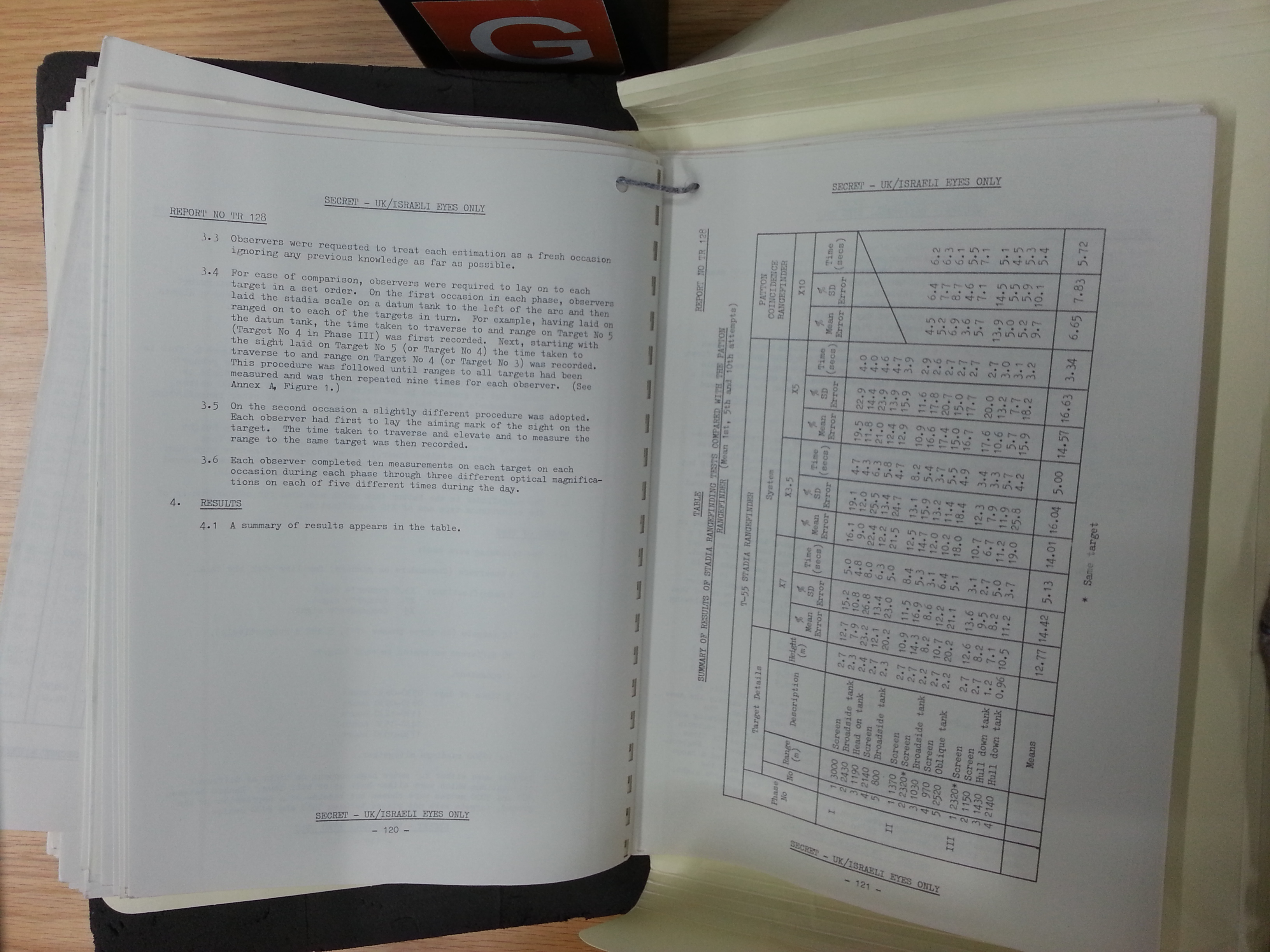
It is stated in page 122 of the report (page 65 of the photo album) that the ranging errors only increased slightly with distance. Surprisingly, the precision of rangefinding against hull-down tanks was hardly affected by the fact that half of the target was out of sight. It is also mentioned on page 123 that the light conditions at various times during the day did not make a significant difference in the ranging process. It could be hypothesized that operator skill and experience in range estimation can make a large difference in overcoming the shortcomings of stadiametric rangefinding.
For reference, the report notes that unaided range estimation by eye results in a mean error of 25%. This information lines up perfectly with a report on the Fifth Annual Army Human Factors Engineering Conference where it is written that a British study showed that a 25% error was found for unaided visual range estimation. The study also showed that on average, a 15% error was found for range measurements using an optical stereoscopic rangefinder. Additionally, a study conducted by The Human Resources Research Organization (HumRRO) found that only 15% of human subjects could physically use a stereoscopic rangefinder, and a second study conducted with 120 men who were given five weeks of training with stereoscopic rangefinders revealed that only 10% could meet or exceed the required standard of accuracy. Furthermore, independent studies have shown that the stresses induced during combat will have a noticeable negative effect on the accuracy of ranging using stereoscopic rangefinders due to the mentally intensive nature of the task. Also, measuring the range to a moving target or an intermittently disappearing target (due to obstructions, for example) was found to be nearly impossible.
Although the details of the results from the British study were not provided, a direct comparison between the 15% error figure given and the 14.57% error figure given in the British-Israeli report shows that the stadiametric rangefinder of the TPKU-2 is functionally of equal precision as a stereoscopic rangefinder when both are operated by trained personnel, and the stadia system has the major advantage of only requiring the normal clarity of eyesight expected from a tank commander or gunner rather than needing specially picked operators. The high theoretical ranging accuracy of stereoscopic rangefinders is usually not achieved even during training, let alone in combat conditions.
On the other hand, an optical coincidence rangefinder is much more practical as it does not require operators with special mental capabilities and it can be just as precise as a stereoscopic type. The British-Israeli report includes data in page 121 showing that when ranging the same targets as the T-55 from 970 meters to 2,520 meters, a "Patton coincidence rangefinder" had a mean range measurement error of only 6.65% at the expense of taking an average of 5.72 seconds for each measurement. It is mentioned that there was a noticeable negative correlation between ranging precision and range, but even so, it is clear that the replacement of a stereoscopic rangefinder with a coincidence type in the M103A2 (the same rangefinder as in the M60) gave it a quantifiable advantage over the entire T-10 series in general. However, the catch is that conversions of M103A1 tanks to the M103A2 standard only began in 1964, so this advantage took a rather long time to materialize.
TKN-1T

The T-10 was furnished with a TKN-1T active infrared monocular periscope. As the TPKU-2 lacked any provisions for nighttime use, it was necessary to swap it out for the TKN-1T before commencing night operations. The device fits into the same periscope slot without any modification. The angle of elevation is adjusted with the right cupola handle in the same way as the TPKU-2 and the target designation system continues to work with the TKN-1T installed, so the basic mode of fire control does not change when operating at night except for the greatly reduced viewing distance and total reliance on the night vision periscope. As before, to designate a target for the gunner to engage, the commander simple aims at it in the TKN-1T viewfinder and presses the thumb button on the left handle.

The TKN-1T has a fixed 2.75x magnification, making it only suitable for observation at short distances even if the battlefield is illuminated by other sources of infrared light. The angular field of vision is 10 degrees. The high voltage signal needed to amplify the infrared light is supplied by the BT-2-26T power supply unit.
Illumination for the periscope is supplied by an OU-3T infrared spotlight. The infrared light from the spotlight illuminates the target, and the reflected light entering the objective lens of the periscope is then amplified by an image intensifier tube operating on 17 kV. The power cable supplies power to the transformer housed in the box on top of the eyepiece, and another cable runs from the transformer to the image intensifier installed inside the device itself. To turn on the OU-3T spotlight, the commander simply flips an on-off toggle switch located on the side of the left handle.

Using the OU-3T in the active infrared mode will enable the commander to identify tank-type targets at a distance of only 250-300 meters. Due to the short viewing distance, the TKN-1 is generally only suitable for spotting enemy tanks that are also using active infrared illumination, for following the fall of tracers, for observing the impact of shots and for spotting the muzzle flash of enemy tanks. The view through the eyepiece of the TKN-1S is shown in the two photos below (image credit to kmshik from the GAZ 69 forums).


COMMUNICATIONS

The turret wall on the side of the commander's station is largely occupied by the tank's communication facilities. These include the radio transceiver set, the power supply box for the radio, the communications relay box, the radio antenna frequency tuning box, and a slot in the turret wall for the whip antenna. The bulky radio transceiver and radio power supply box are installed side-by-side on the shelf between the turret wall and the turret ring. This is the same layout as in the T-54 and shares the same disadvantage of decreasing the width of the commander's station with the advantage of providing the commander with free and easy access to the radio transceiver. This is necessary for him to control the communication channel fluidly and also to troubleshoot any issues if they arise. The model of radio transceiver installed in the T-10 series directly corresponded to the models that were standardized at the time of introduction. For the original T-10, the 10RT-26E radio was installed.
A fuze box for the tank's electrical network is installed above the radio transceiver, and the radio antenna frequency tuning box is installed above it. It connects the radio transceiver to the whip antenna. For communication between crew members, the tank was equipped with the TPU-47-2 intercom system.
Additionally, the tank is equipped with an electric S-58 buzzer (horn) to allow infantry to get the attention of the tank crew. The buzzer is located inside the tank on a bracket above the accumulator battery rack. It is activated by a button located near the left rear marker light.
10RT-26E

The commander is also in charge of the single 10RT-26E short wave radio set mounted to the turret wall next to him. The radio is designed to operate in the 3.75-6.00 MHz frequency range. All Soviet armoured vehicles from the later half of WWII and the immediate postwar period featured a 10RT series radio, but by the early 50's, the series was rendered obsolete by a new government decree allocating the 20.0-22.4 MHz frequency range for the exclusive use of tank radios.
The production of the venerable 10RT series ceased entirely in 1956, having been replaced by the R-113 radio set. From January 1957 onward, the new R-113 radio transceiver and R-120 intercom system began replacing the older types on existing T-10 tanks during scheduled maintenance. The T-10A model (introduced in May 1957) came with the new communications suite as standard, as did the T-10B and T-10M.
R-113

R-113 radio transceiver set. A video of an R-113 radio in operation can be found here (link). The R-113 belonged to the first generation of Soviet tank radios designed in the postwar era and it became the standard tank radio for short to medium range communications. It is a typical VHF radio operating in the 20-22.375 MHz frequency range with a maximum range of 20 km with the whip antenna extended, but the range is reduced to 8-12 km in the presence of high noise interference and it is further reduced to 10 km in the presence of jamming. The R-113 could be tuned to 96 frequencies within the limits of its frequency range. During combat, tanks in tank platoons usually have their radios kept in the simplex receiving mode to receive orders from the platoon leader, while the platoon leader operates his radio in the half duplex mode, although he is often forbidden from transmitting except in emergencies. In general, all tanks mainly operate in the receiving mode to receive orders from the company commander, but in some cases, total radio silence is practiced by tank commanders prior to an attack in order to gain the element of surprise. In such cases, communications may be carried out using signal flags and by relying on pre-practiced drills.
The extendable whip antenna for the radio system is located on the side of the turret just next to the commander's cupola, behind the gunner's TPB-51 vision block. The photo below is from Dave Haskell.

The photo shows the commander of a T-10M tank belonging to the 49th Separate Tank Battalion, Senior Sergeant S.N. Shabalin in his tank while stationed at GSFG in the summer of 1974. In the photo, you can see that he is actually seated on the gunner's seat and his right hand is resting on the commander's seat. The R-113 radio can be seen just behind his right shoulder, and the cables that connect his headset to the communications system are clearly visible.

The tank also has a supply of 20 signal cartridges. The signal gun can be used in times of emergency, but their main purpose is for the commander to signal other troops to coordinate night battles when total radio silence is needed. The signal shells are bright enough to be visible from a very long distance and can be easily seen by enemy forces, thus revealing the position of the firer. However, the shells do not produce enough light to illuminate objects on the ground.
GUNNER'S STATION

The gunner's seat is mounted on a fixed tubular post which is bolted to the rotating turret floor. The seat can be adjusted in height and the cushion can be folded down to permit easier access to the hull. The gunner is not provided with a footrest so he simply places his feet on the rotating floor, and although there is no turret basket on any T-10 model, there is a short fence on the perimeter of the rotating floor in front of the gunner to ensure that his feet does not slip off accidentally.


The gunner only has a single TPB-51 aimed 35 degrees to the left for general vision outside of his sighting devices. The two photos below show the position TPB-51 relative to the night vision sight of the T-10M. The photo on the left below (credit to Vladimir Yakubov) shows the exterior of the tank with the (cracked) square periscope aperture window clearly visible in front of the radio antenna post and to the left of the night vision sight housing, which has been blanked off. The photo on the right below (credit to Stefan Kotsch) shows the square hole in the turret roof where the TPB-51 would fit and its close proximity to the opening for the night vision sight.


As usual, a spare periscope is provided. It is worth noting that the T-54 had an MK-4S periscope in a fully rotating mount where the TPB-51 is installed on the T-10, thus granting its gunner much more freedom in terms of vision. This was replaced with a periscopic night vision sight on the T-54B, but the T-55 compensated by installing a forward-facing general vision periscope on the turret roof above its TSh2-22 sight. In both cases, the presence of a periscope to supplement the articulated telescopic sight was a deliberate design solution to not only provide the gunner with good visibility but also to allow him to see over the edge of cover when the tank is in a turret-down position with only the optical instruments on the roof exposed. In such a position, the gunner's primary sight would be useless for surveillance. The need for such a periscope did not exist for the T-10A, T-10B and T-10M as all of these tanks had a periscopic primary sight, but for the T-10, the lack of a periscope was a tangible drawback. Still, having the TPB-51 to cover the 10 o'clock sector of the turret was certainly better than nothing as it expanded the gunner's view of the surrounding environment.
To put this into a greater context, it should be mentioned that the gunners of virtually all NATO tanks were not provided with general vision periscopes and had to rely entirely on the view from their sights and the directions given by the commander, or their control of the gun and turret had to be overridden by the commander.
The gunner's intercom relay switch is on the turret ceiling directly above him. It is a somewhat unusual location, but completely serviceable. The gunner also has access to the turret rotation lock.
SIGHTING COMPLEXES
The original T-10 had an articulated telescopic TSh2-27 sight. The design of the sight is principally identical to all others in the TSh2 series, including the TSh2-22 of the T-54 obr. 1951 medium tank, so it was not more advanced than the standard medium tank in the Soviet Army in 1953. One of the chief complaints from users of early T-54 models like the T-54 obr. 1947 and T-54 obr. 1949 (TSh-20) and heavy tanks like the IS-2, IS-3 and IS-4 (TSh-17) was the relatively limited 4x magnification of the TSh series of articulated telescopic sights. As such, the TSh2 series was created with two magnification settings: 3.5x and 7x. By implementing variable magnification in the sight, the gunner could enjoy both wide vision and high power magnification as the situation dictated. The "2" suffix at the end of the "TSh" designation indicates that the TSh2 series belongs to the second generation of articulated telescopic sights produced in the USSR.
The 7x magnification of the high setting was most likely chosen because it was more ideal from the standpoint of practicality. To better understand this, it should be understood that an optical sight with no magnification would allow the gunner to see and identify a tank from a distance of 1.0-1.5 kilometers. According to Soviet figures, an optical sight with 4x magnification increases this distance to 2.5 kilometers, an optical sight with 5x magnification further increases this range to 3.0 kilometers, and according to the table below, an optical sight with 7x to 8x magnification increases this range to 4.0-5.0 kilometers.
The table below is from page 12 of the article "Forging the Thunderbolt" published in the January-February 1976 issue of "Armor" magazine. The range figures denote the range at which the respective targets are recognizable by the naked eye or when viewed through a magnified optic.

Based on this, a 4x sight should have been sufficient for a postwar tank as it already permits a tank gunner to identify a tank from beyond the maximum effective range of his tank gun, but a tank gunner does not only need to be able to identify a target but also engage it. With a 7-8 power optic, a gunner can not only spot tanks from beyond the maximum effective range of his main gun but also discern more minute details to differentiate between different tank models and more importantly, he can lay his reticle precisely on the individual parts of a tank from normal combat distances, i.e. from 1.5 kilometers or perhaps more. The ability to see various soft-skinned vehicles from 4 kilometers or more also allows the gunner to conduct long-range direct fire with HE-Frag shells. A further increase in magnification does not necessarily increase the effective direct-fire range of the main gun due to the limitations in the mechanical accuracy of the weapons. Case in point; at two kilometers, the probability of a first-round hit on an ATGM emplacement with a HE-Frag shell is 20% whereas at three kilometers, the probability drops to less than 5%.
Contrary to expectations, the magnification power of T-10 tank sights was higher than that of the Conqueror's No. 10 sight, which had a slightly lower 6x magnification. The disparity widens when the Conqueror is compared to the T-10M, which had a sight with 8x magnification.
T-10
TSh2-27, TSh2-27K

The TSh2-27 is an articulated telescopic sight with manual range adjustment. The sight can be switched between two magnification settings: 3.5x and 7x. The field of view in the 3.5x setting is 18 degrees and the field of view in the 7x setting is 9 degrees. The low magnification setting would be used to scan for targets or for general observation whereas the high magnification setting would be used for laying the gun on the target, engaging it, and conducting fire correction (if not done by the commander).
The main characteristics of the sight - magnification and field of view - were excellent for the early 1950's and were still more than adequate during the 1960's, and the ergonomic design of the system was good. The large brow pad surrounds the gunner's forehead and temples, and the eyepiece itself is ringed by more rubber padding. Being an articulated sight, the telescopic tube and eyepiece of the TSh2-27 is mounted to the turret roof and suspended in a fixed position, while only the articulated aperture assembly moves up and down coaxially with the main gun. This allows the gunner to stay in his seat in a comfortable posture while using the sight without needing to follow the eyepiece up and down as the gun is elevated and depressed during operation as in some early WWII era telescopic sights. The height of the eyepiece can be adjusted by adjusting the frame attaching the sight to the turret ceiling.

An additional feature of the TSh2-27 that the previous generation of TSh sights lacked is a stadia rangefinder. The stadia rangefinder allowed the gunner to independently estimate the range to a target from a range of 1.2-2.8 kilometers. However, as mentioned earlier, the commander is responsible for providing an initial range estimate to the gunner using his own stadia rangefinder.

The TSh2-27K variant is a slightly modified version of the TSh2-27 with an additional range scale for HEAT rounds. This allowed T-10 tanks to fight tanks much more confidently by relying on modern HEAT ammunition instead of legacy armour-piercing shells. However, there appears to be no TSh2-27 variant with a range scale for APDS rounds, so if T-10 tanks were supplied with 3BM7 APDS rounds, the gunner would need to use firing tables.
T-10A, T-10B
TPS1


When the T-10A entered service in 1956, it came equipped with the highly advanced TPS1 sighting complex. The sight was also carried over to the T-10B when it entered service in 1957. The TPS1 is paired with the PUOT "Uragan" stabilizer on the T-10A and paired with the PUOT-2 "Grom" stabilizer on the T-10B, retaining the same function in both setups with only minor technical nuances. Development of the revolutionary TPS1 began during the early 1950's and concluded in 1955, with mass production beginning in 1956 and ending in 1958. There are two gyroscopes in the sight - one rate gyro to stabilize the field of view of the optical channel and another rate gyro to serve as a reference system for calculating lead.
The TPS1 features independent vertical stabilization with a range of elevation of -7.75 degrees to +20.75 degrees and an elevation speed of 0.05 degrees per second to 3 degrees per second. The weapons control scheme of the "Uragan" stabilizer slaved the main gun and coaxial machine gun to the TPS1 and only permitted the weapons to be fired when the elevation angle coincided with the elevation angle of the sight. The accuracy of the independent sight stabilization system was such that the point of aim did not deviate by more than of 0.5 mils during normal operation.
Thanks to these technological achievements, the gunner could maintain visual contact with a target while the tank is moving across extremely rough terrain even if it is beyond the gun elevation or depression limits of the gun. When firing on the move on undulating terrain, the gunner could track a target and simply hold his finger on the trigger button when he has obtained the ballistic solution, and the fire control system would automatically fire the gun when the tank pitches in such a way that the elevation angle of the gun matches the sight.
This sophisticated control scheme not only provided an considerable increase in firing accuracy but also partly nullified the disadvantages of the low gun depression limit of the T-10 series and gave the tank an indisputable edge over the newest models of the T-54 series and T-62 series appearing the late 1950's and early 1960's, as these medium tanks had a much simpler fire control system lacking independently stabilized sights.
The TPS1 could be switched between two magnification settings; 3.1x and 8.0x, and as before, the former setting would be used to scan for targets at short distances or for general observation whereas the latter setting would be used for servicing the target. The field of view in the low magnification setting is 22 degrees and the field of view in the high magnification setting is 8.5 degrees.


The fire control systems of the T-10A and T-10B lack an optical rangefinder, but the TPS1 features a somewhat innovative stadia rangefinder mechanism. Three stadia rangefinder markings calibrated for different targets are etched on three different locations on a glass disc in 90-degree intervals. The glass disc is placed next to the viewfinder in such a way that one edge of the disc will appear on the right edge of the viewfinder. By turning the rangefinder setting dial located on the right side of the sight, the glass disc is rotated to cycle between the three different rangefinder markings. The rangefinder setting dial is marked (22) in the cutaway drawing above. The three settings are: for a towed anti-tank gun with a height of 1.2 meters, a medium tank with a height of 2.7 meters, and a heavy tank with a height of 3.0 meters. The fourth setting is void and provides the gunner with a less cluttered field of view.
There are also three fixed range marks for OF-471N rounds on the vertical line below the center chevron. The fixed range marks are calibrated for a distance of 1.0 km, 1.8 km and 2.0 km. This is designed to allow the gunner to use the bracketing gunnery technique to rapidly determine the range to the target at normal combat ranges by immediately firing the first shot without prior range estimation. In this system, bracketing is done by firing at the target with the 1.0 km range mark, determining if the shot went over or short, and then using a range mark for a shorter range if the shot went over or a range mark for a longer range if the shot went short.
The drawings below show the viewfinder of the sight in the 3.1x magnification setting and in the 8.0x magnification setting with the stadia rangefinder adjusted for a 2.7-meter target.

Additionally, the gunner has the option to place or remove a high-contrast filter by turning a dial on the left side of the sight, and as usual, illumination for the reticle (including all markings in the viewfinder) with a lightbulb can be turned on for nighttime observation.
The sight is suspended from the roof of the turret on a special frame.

Theoretically, it is possible to use the coaxial machine gun as a ranging gun. However, this would not be possible with the stabilizer operating in the automatic mode due to the lag issue which discounts any possibility of exploiting the coaxial machine gun in this way under most situations. Another hurdle is that neither B-32 or BZT were ballistically matched to any 122mm round supplied for the D-25TS.
Due to the high complexity and sensitivity of the TPS1, a backup sight was deemed necessary to ensure that the tank would not lose its firepower spontaneously during combat from technical issues or from battle damage. As such, the TUP sight (standing for "Simplified Tank Sight") was created and installed in the T-10A and T-10B together with the TPS1.
TUP-21

The TUP-21 is a simple fixed telescopic sight. It is meant only as a backup to the much more complex TPS1 primary sight and would not be used except in emergencies. The aperture and erector tube of the sight is mounted to the main gun above the trunnion at a relatively unusual position. This was done because the space directly beside the D-25TS was already occupied by the parallelogram linkages connecting it with the TPS1 sight. Two periscopic extensions redirect the optical path to ensure that the eyepiece is placed at the gunner's eye level.

To use the sight, the periscopic eyepiece extension must be swiveled from the stowed position to the ready position where the gunner's eye would be (refer to drawing above). When placed in the stowed position, the eyepiece is flush to the recoil guard of the cannon breech and should not interfere with the gunner's workspace.


The TUP-21 has a fixed 4x magnification and a field of view of 12 degrees. As shown in the drawings below, there is a fixed range scale for 'БР/ТУП' rounds for a distance of up to 3,600 meters in increments of 200 meters. This stands for 'armour-piercing blunt-tipped', referring to the BR-471B APBC rounds. To aim with the sight, the gunner first estimates the distance to the target using the reticle markings or receives the range estimate from the commander, and then he simply raises the gun with the manual gun elevation handwheel until the appropriate range mark for the desired ammunition type is laid on the target. Engaging point targets with HE-Frag rounds has to be done by using a conversion chart for the range scales, and engaging targets with the coaxial DShKM would have to be done by simply following the fall of the tracers. To engage moving targets, the gunner first determines the amount of lead needed using the lead markings, and then proceeds with the rest of the procedure as before.

The distance markings for the TUP-1 somewhat resemble the distance and lead grid found in typical American tank sights of WWII vintage, but differ in that only a single row of lead markings comprised of vertical dashes and small chevrons are provided along the center chevron and two columns of range scales for the coaxial machine gun and the main gun are provided. On American sights, the grid is meant only for one type of AP round from the main gun, and firing from all other ammunition types has to be done using firing tables or by following the tracers in the case of the coaxial machine gun. It was noted in a Soviet tank technology journal article that the American M8 sight (with an identical reticle layout as all other American tank sights) that the presence of a grid obstructed the gunner's view, although it was convenient to use when lead is required. Although there are no pictures of the view through the TUP-21 viewfinder, it is probably safe to assume that the range scales would also obstruct the gunner's view in the same manner.
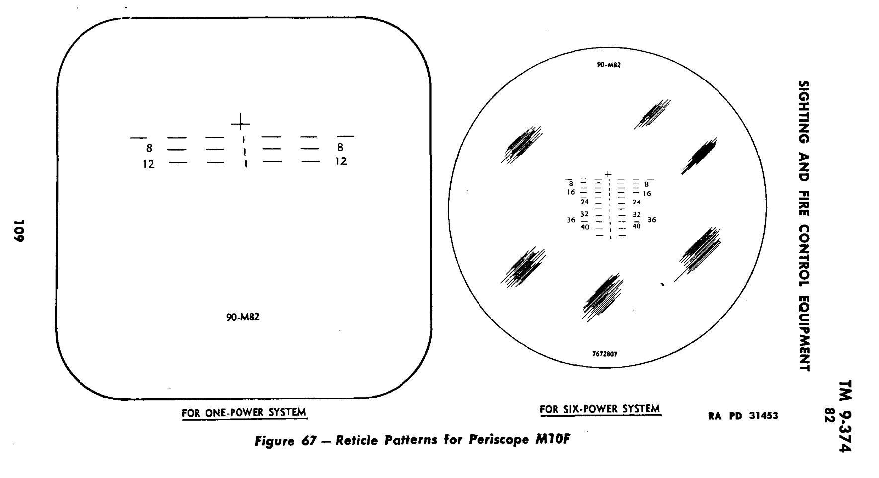
The simplification of the aiming system greatly reduced the precision of fire compared to the TPS1 primary sight, but it was still possible to engage targets from up to two kilometers without serious difficulty and the magnification of the TUP-21 was sufficient for identifying a tank-type target at more than two kilometers. The fixed mounting of the TUP-21 to the main gun eliminates the possibility of a mechanical misalignment and contributes to high accuracy, but the disadvantage is that the eyepiece would follow the gun up and down as it is elevated and depressed, so the gunner must adjust himself to keep his eye on the eyepiece. As such, it would also be much less convenient to use the sight when the main gun stabilizer is active.
Considering these limitations, it is still worth keeping in mind that even though the TS-17 primary sight of the IS-3 has a slightly wider field of view and includes a range adjustment dial, it also has the same fixed 4x magnification. As such, even if a T-10A or T-10B is forced to operate in a degraded mode with only the TUP-21 sight, the sighting system does not regress very far below the level of the IS-3.
T-10M
T2S-29-14 "Udar"

The T2S-29-14 was the most advanced sighting complex in the world at the time of its introduction in 1957 and firmly retained that title for the earlier half of the 1960's before being surpassed by another Soviet tank sighting complex. The progress made in implementing the features of the T2S sight was instrumental in the research and development of all future Soviet tank sights and fire control systems. Despite being a more technically complex product, the T2S-29-14 did not have the reliability issues of the TPS1 so it was judged that a backup sight like the TUP-21 was no longer needed. The sight facilitated a maximum direct fire range for APCBC ammunition of 4,000 meters, for HE-Frag ammunition it was 6,000 meters, and for the coaxial KPVT machine gun it was 2,000 meters.
Like the TPS1, the T2S-29-14 sight could be switched between two magnification settings; 3.1x and 8.0x, and as before, the low magnification setting would be used to scan for targets at short distances or for general observation whereas the high magnification setting would be used when laying the gun on the target, firing at the target and applying corrections. The field of view in the 3.1x magnification setting is 22 degrees and the field of view in the 8.0x magnification setting is 8.5 degrees.
Besides independent stabilization, the T2S-29-14 sight included a Delta-D system. This system automatically and dynamically measures the speed of the tank using a tachometer to calculate the distance traveled and automatically subtracted this from the range to the target in the ballistic solution. The Delta-D system in the T2S-29-14 also took the orientation of the turret in azimuth as an input and dynamically generated new calculations using a cosine function. For example, if the T-10M was moving diagonally obliquely relative to the gunner's target at a 60° angle, the system would subtract the distance at a rate equivalent to the Cosine of 60 degrees, or 0.5. As such, if the tank was moving at a steady speed of 18 km/h (5 m/s), then the system would subtract the distance at a rate of 2.5 m/s.
The system would continue to run until it is reset by the gunner, so the gunner could make a single range measurement and fire continuously at the target while the driver performs maneuvers with the tank without needing to update his range measurement. The distance traveled by the tank was calculated by measuring the engine driveshaft speed; it was an odometer, to put it simply, but this system was independent from the driving odometer of the tank.
The Delta-D system continuously corrected the ballistic solution in the sight according to the change in the distance from the tank to the target, and the automatic lateral lead automatically set the lateral lead needed when firing at a moving target.


One unusual feature of the T2S-29-14 is the layout of the "Cheburashka" control handles. Typically, the handles are placed below the eyepiece of the sight, preferably somewhere in front of the gunner's chest or midriff. On the T2S-29-14, the control handles are located behind the eyepiece of the sight and the potentiometers of the control box are wrapped around the tube of the eyepiece optical channel, so the gunner must have his hands raised up to eye level to operate the control handles. It is worth noting that although the location of the control handles is certainly unconventional, being unconventional does not necessarily translate to being ergonomically deficient. Gun elevation is controlled in the normal way with the handles twisted forwards and backwards to depress and raise the gun, but to control turret traverse, the handles are turned like a steering wheel in the same way as the control handles - or "Cadillacs" - of an American tank. The index buttons on both the left and right handles are for firing the coaxial machine gun and the thumb buttons on both of the handles are for firing the main gun. Strangely enough, although there are two buttons for the main gun and the coaxial machine gun each, the manual states that the gunner can choose to press one or both of the two buttons to fire the associated weapon and there does not appear to be any difference either way.

Inputting range data is done by turning the large range adjustment dial located between the control handles and the eyepiece of the sight. It is shown in the drawing above, labeled (36). The sight is zeroed for a distance of 1,000-1,200 meters. In the sight viewfinder, the lead markings are spaced 4 mils apart and both the vertical lines and chevrons are 2 mils tall.

Thanks to the inclusion of a form of independent horizontal sight stabilization, the T2S-29-14 featured special provisions for engaging moving targets. In this system, the sight head remained locked in traverse to the turret, but a vertical line in the viewfinder, joined to an internal gyroscope, allowed deflection angles to be calculated with the help of ballistic computer and a timer. Using the range data inputted by the gunner, the sight can automatically calculate the amount of lead needed for a moving target and create a new point of aim. The process relies on the internal gyroscope of the sight to create a fixed reference point from which the lateral movement of a moving target can be compared via the horizontal stabilization of the sight. By combining the rate of rotation of the sight (together with the turret) as the gunner tracks the target with a range estimate from either the gunner or commander, the sighting complex can determine the necessary horizontal offset to ensure that the shot will land on the target.
Initially, the vertical lead indicator line is locked to the reticle and is centered on the central chevron. The central chevron, along with the lead markings, is fixed within the viewfinder and to the sight itself. To determine the lateral lead, the gunner must first activate the lead computing system to unlock the lead indicator line from the reticle. Then, the gunner tracks the target by holding the central chevron on it using the control handles. The vertical lead indicator line is gyroscopically stabilized to maintain its initial bearing, so when the central chevron moves to the right or to the left as the target is being tracked, the static vertical line will appear to shift to the left or to the right relative to the central chevron. The T2S-29-14 sighting complex allows the target to be tracked in this manner until the internal timer finishes its countdown, whereupon the vertical indicator line is locked to the viewfinder and it stops moving relative to the central chevron. The intersection point between the vertical lead indicator line and the lateral lead correction scales becomes the new point of aim. In the drawing below, the tank target seen through the sight appears to be 1,550 meters away and the vertical lead indicator line has stopped at the first secondary chevron. This means that the gunner must use the first secondary chevron as his new aiming point in deflection.

Unlike the previous sighting complexes used on the T-10, the coaxial KPVT machine gun is ballistically matched to the HE-Frag rounds up to a certain distance. As shown in the drawing above, the range markings for the KPVT and HE-Frag ammunition are similar up until 1.2 kilometers where 14.5mm bullets begin to drop off rapidly as they approach the limits of their effective range. Because of this, it is possible to rapidly and accurately engage point and area targets with HE-Frag shells up to 1.2 km as the margin of error in the range estimation is small enough to be irrelevant due to the explosive nature of the HE-Frag ammunition. Nevertheless, the main method of range determination was with the stadia scales.
According to a report on the Fifth Annual Army Human Factors Engineering Conference, a British study showed that a 25% error was found for unaided visual range estimation and a 15% error was found for range measurements using a stereoscopic optical rangefinder. Additionally, a study conducted by the The Human Resources Research Organization (HumRRO) found that only 15% of human subjects could use a stereoscopic rangefinder, and a second study conducted with 120 men who were given five weeks of training with stereoscopic rangefinders revealed that only 10% could meet or exceed the required standard of accuracy. Furthermore, studies have shown that the stresses induced during combat will have a noticeable negative effect on the accuracy of ranging using stereoscopic rangefinders due to the mentally intensive nature of the task. Also, measuring the range to a moving target or an intermittently disappearing target (due to obstructions, for example) was found to be nearly impossible.
Of course, rangefinding from any optical rangefinder is practically impossible if the vehicle is moving over uneven ground unless the rangefinder is stabilized. The first stabilized rangefinder did not come about until 1963, when the TPD-43B independently stabilized sighting system with an integrated optical coincidence rangefinder was introduced with the T-64 main battle tank.
There is not much information on the opinions of Soviet engineers on the precision of this method of rangefinding, but the normal error margin for the .50 caliber ranging system of the Chieftain is claimed to be 50 meters at a distance of 1,000 meters, which is equivalent to a 5% error. However, the rangefinding system in the Chieftain relies on fixed aiming points in the sights, so the claimed degree of accuracy is most likely not achievable if the range to the target does not coincide exactly with the fixed aiming points.
It is important to note that the ranging time required for the operation of a ranging machine gun is much less than that required of a stereoscopic rangefinder, and that a ranging machine gun also helps give the gunner the ability to loosely sense and account for wind effects. However, using a stadia rangefinder takes much less time and will allow the gunner to fire the first shot in an engagement.
In any case, whether by stadia rangefinding or ranging machine gun, the results are much better than from simple visual range estimation with the naked eye. With an error margin of 25%, firing on tank-type targets at ranges greater than a few hundred meters is ineffective; tests showed that at a distance of 1,000 meters to 2,900 meters, the probability of hitting the front silhouette of a tank target with an APCBC round with the M62-T2 was just 6-20% with visual range estimation.
On a side note, it is worth mentioning that the location of the sight resulted in a local weakening of the frontal turret armour. The reduction in the thickness of the turret casting is evident in the photo below (taken by Stefan Kotsch). The only redeeming features are that the sight is quite narrow so the zone of reduced armour thickness is also quite narrow, and the external shaping of the turret casting in front of the sight is unchanged so it is still likely for an impacting projectile to ricochet off the armour, in which case the reduction in armour thickness has much less of an effect.


A set of spare parts for the T2S-29-14 are kept in an aluminium box on the turret wall at the loader's station, next to the first-aid kit.
TPN-1-29-14

When it entered service in 1958, the T-10M featured the "Luna" night vision sighting system consisting of the TPN-1 sight and the L-2 infrared spotlight. The TPN-1-29-14 is a variant of the TPN-1 sight which was used on the T-54B (TPN-1-22-11), T-62 (TPN-1-41-11), T-64 and T-72 (TPN-1-49-23) and other Soviet tanks. The only noteworthy differences between these modifications are the reticle markings and the design of the linkages that connect the sight to the cannon. The photo below (credit to Dave Haskell) shows the L-2 "Luna" spotlight with the TPN-1-29-14 sight window in the background.


The sight can be used to identify a tank-type target at a maximum distance of 750-800 meters in the active mode with illumination from the "Luna" IR spotlight. The T-54B medium tank entered service in the same year as the T-10M (1957) and it was was equipped with a TPN-1 night vision sight as well, so the T-10M did not have any advantage over its medium counterpart in this particular department.
The passive mode allows the same type of target to be spotted at ranges of up to 500 meters if the intensity of ambient light is no less than 0.005 lux, which is the typical brightness of a moonless, starlit night with clear skies. The clarity of the image - and thus the distance at which targets can be seen and identified - increases with the brightness of ambient light. Based on research into other 1st Generation night vision systems, the identification distance may be expanded to around 1,000 m on moonlit nights with clear skies (0.05–0.3 lux), and it should be possible to spot tanks at distances of more than 1,300 m during dark twilight hours (3.4 lux), although low magnification and mediocre image resolution complicates target observation at longer ranges. The sensitivity of the image intensifier in the sight should be decreased to provide better image quality during twilight hours.
Illumination shells and bombs can be used to great effect in conjunction with light intensifying sights like the TPN-1.

When operating at night, the "Liven" stabilizer is switched from the "day" mode to the "night" mode. This switches the stabilization system from a gun-follows-sight scheme where the gun stabilizer is slaved to the independent two-plane stabilizer of the T2S-29-14 primary sight to a sight-follows-gun scheme where the TPN-1-29-14 is slaved to the gun stabilizer. The precision of stabilization is consequently reduced but not significantly enough to have a meaningful effect on combat accuracy due to the relatively short viewing distance provided by the night vision sight. If night fighting is conducted using flare illumination and with the IR spotlight converted to a white light spotlight, the T2S-29-14 primary sight is used instead and the stabilizer is set in the "day" mode.
The TPN-1-29-14 is installed directly above the T2S-29-14 sight in a circular slot in the turret roof. The eyepiece of the sight is placed directly above the eyepiece of the T2S-29-14. From the outside, the sight is protected by a cast steel armoured hood and the objective window is sealed with a simple armoured cover when not in use. The armoured cover is a simple plate with a handle that slides over the window into a pair of dovetailed tracks. The armoured hood on the T-10 has a sloping roof so that it does not obstruct the commander's view from his cupola periscopes. This was necessary because the sight was not offset to the left of the main sight like on the T-54 and T-62.


Because the TPN-1-29-14 eyepiece is located above the eyepiece of the T2S sight, the gunner should adjust the height of his seat to maintain a comfortable posture when using the night sight. Interestingly enough, the control handles on the T2S sight would be at the level of the gunner's chest in a much more natural position when he is using the night sight.
As shown in the drawing below, the ends of the vertical lines and the chevron in the viewfinder are calibrated to predetermined distances. The topmost mark corresponding to a distance of 250 meters for AP round from the M62-T2 cannon only corresponds to a distance of 100 meters for the coaxial KPVT machine gun. The difference in the ballistic drop remains roughly similar with the smallest difference being at the center chevron, where there is a difference of 100 meters. The largest difference is at the lowest vertical line where the points of impact of the cannon and the coaxial machine gun would differ by 250 meters. Again, the mismatch between the ballistic trajectory of the APCBC rounds and 14.5mm bullets is clearly demonstrated. The markings are designed to facilitate quick and reasonably accurate engagement using the battlesight gunnery technique.

The sight does not include a stadia rangefinder or any other provision for range estimation besides the reticle markings, but this was not considered a debilitating drawback due to the limited viewing distance provided by the TPN-1-29-14. Given that the maximum practical combat distance with the sight was just 800 meters, the center chevron in the reticle (700 m) would serve as the universal battlesight and it could be used to engage practically all types of targets. When firing at tanks, the gunner should aim at the center of the hull. If the target is closer than 700 meters, the shot will land on the upper hull or on the turret. If the target is at 700 meters or more, the shot will land on the center of the hull or on the lower glacis. To engage targets with HE-Frag rounds, the gunner has to either rely on the relatively good point blank range of the OF-472 shell or use the burst-on-target gunnery technique.
The night vision capabilities of the "Luna" system were generally quite good by the standards of the 1950's, but it was limited by the low output of the incandescent lamp in the L-2 spotlight. An M103A2 with a xenon arc lamp spotlight (fitted since 1967) had a 75-million candlepower output that could illuminate a target at close to two kilometers, but the M103 series lacked any infrared night vision sighting systems, let alone a passive light intensifier system as found in the TPN-1. Despite the large range advantage that such a powerful spotlight could have granted the M103A2, the downsides of relying entirely on white light illumination with no possibility of switching to infrared imaging were much more compelling. Earlier M103 tanks were in a worse position as they only had a Hinds-Crouse incandescent white light spotlight of limited power. The worst by far was the Conqueror as it never had any night vision capability whatsoever. It even lacked infrared headlights for driving, and as such, not only lacked a night fighting capability but also lacked the ability to participate in stealthy night maneuvers.
In 1960, a small scale programme to upgrade existing T-10 series tanks with modern night vision equipment was started. The quantity of tanks that received the upgrade is unclear, but the upgrade package included the TPN-1-29-14 night sight, the L-2 "Luna" infrared spotlight, the TKN-1T infrared periscope, the OU-3T infrared spotlight, the TVN-1T, the FG-100 infrared headlight, as well as all of the associated electrical equipment. The photo below shows one example of a T-10 upgraded with night vision equipment while retaining all other characteristics of a typical T-10. This variant is known as the T-10 obr. 1960.

Due to the lack of an existing periscope opening on the turret roof of the T-10, T-10A and T-10B, the tanks that were retrofitted with a night vision sight had to undergo factory-level modifications. A square-shaped hole had to be cut into the turret roof and a hole had to be made in the turret to fit the electrical fittings to supply power to the external infrared spotlight, which was simply added to the right side of the gun mask by welding. The drawings on the left below show the locations of the equipment of the "Luna" night vision system in the turret of a T-10 obr. 1960 and how the TPN-1-29-14 sight is linked to the D-25T cannon, and the photo on the right below shows the TPN-1-29-14 installed in modernized T-10.


LOADER'S STATION
T-10, T-10A, T-10B
For general vision, the loader is provided with two TPB-51 prismatic periscopes on the sides of the turret, just underneath his cupola. They are aimed in the 2 o'clock and 4 o'clock directions to allow the loader to cover the right side of the turret. This is a notable downgrade from most other Soviet tanks which gave their loaders a rotating MK-4S periscope, but regardless, this seems to be a very minor drawback since the loader is generally more focused on his loading duties and the two TPB-51 periscopes on the sides of the turret are enough to allow him to cover the right side of the turret which is a dead zone for the commander because the commander's cupola is offset to the left of the turret roof.
However, the loader would generally tend to be occupied with his primary tasks such as reloading the coaxial machine gun frequently as it is fed with relatively small 50-round boxes. Even when not actively loading the cannon or the coaxial machine gun, the loader can replenish his ready racks or rearrange the ammunition in the ready racks to more convenient positions so that he is ready for any sudden contact with enemy forces. Scanning the tank's surroundings from his periscopes is quite an unprofitable use of time by comparison.
The internal height of the fighting compartment at the loader's station as measured from the rotating floor to the turret ceiling is 1,600mm. This is functionally identical to both the IS-2 and IS-3 which had an internal height of 1,580mm. The loader also has a cupola which is raised above the turret roof, so in practice, he could have more headroom if he stands directly underneath his cupola when performing some loading actions, but conversely, the slope of the turret roof in front of the cupola drastically reduces the loader's headroom if he is not standing under his cupola. This would not be a problem if the loader is retrieving ammunition from the ammunition racks on the fighting compartment floor or from any of the hull racks as he must bend down anyway, but it could make it more difficult to reload and service the coaxial machine gun because the top cover must hinge upward. On T-10 models up to the T-10B, the coaxial DShKM mount is raised above the bore axis of the main gun, so it is quite close to the turret roof, especially when the gun is depressed. The coaxial KPVT in a T-10M is closer to the bore axis of the main gun, but due to its enormous top cover, the clearance issues are similar.
The D-25T series gun breech assembly has a width of 480mm and the gun is aligned with the centerline of the turret. Since the tank has a turret ring diameter of 2,100mm, the maximum width of the loader's station is 810mm. By contrast, the loader's station in an IS-2 and IS-3 had a maximum width of 660mm and 680mm respectively. Even when the loading assistance device integral to the T-10 is factored in, the loader's station in the T-10 is still wider by a noticeable amount.
According to the article "Human Factors and Scientific Progress in Tank Building", the internal volume of the loader's station in a T-10 is 0.762 cubic meters. This much less than the 1.36 cubic meters of space enjoyed by the loader of a T-55, and it can be explained by the ammunition stowage layout in the T-10. This will be explored later in this article.
The loader's hatch has a diameter of 572mm and a thickness of 20mm. It has a dome shape to provide additional headroom if the loader is standing under his cupola.

The loader was also responsible for manning the external DShKM anti-aircraft machine gun which is mounted on a fixed pintle attached to his cupola. Besides traversing the cupola, the machine gun can also be aimed independently by swinging it around its pintle. This design is unobtrusive to the loader and it permits a full-sized circular hatch to be installed, giving the loader the largest possible passageway for a given cupola diameter. In this case, the cupola has a diameter of 646mm, the hatch has a diameter of 572mm and the hatch opening has an internal diameter of 540mm, as detailed in the drawings below. This is effectively the same design as the loader's cupola on a T-54. The drawback of this design is that when the DShKM is fitted on its mount, the toothed arc for its elevation mechanism physically blocks the hatch from opening or closing, making it necessary to stow the gun away by turning it to the side.


However, there is no mechanical assistance for rotating the cupola, so the loader must rely entirely on his upper body strength to shift it. The pintle juts outside the perimeter of the cupola to accommodate the full circular hatch for the loader, but the heavy DShKM machine gun unbalances the cupola with its weight and makes it difficult to rotate the cupola if the tank is on a slope. To solve this issue, the loader's hatch was designed to act as a counterweight when it is fully opened.

T-10M


The new T-10M turret retained the general shape of the previous turret design, but the level of protection was deeply enhanced. One of the measures taken to improve the resilience of the side turret armour was to replace the two TPB-51 prismatic periscopes on the sides of the loader's cupola with a single fixed TNP periscope on the turret roof aimed in the 1 o'clock direction. This is probably less useful than the two smaller square-shaped TPB-51 periscopes on the side of the turret since the loader would be looking in a forward direction while both the gunner and commander would already be scanning the area ahead of the tank through their own, much better viewing devices. The loader also loses the ability to scan the dead zone on the right side of the turret. Still, there is not much combat value in giving the loader more vision than absolutely necessary, so it does not make much of a difference in the grand scheme of things. The loader's single TNP periscope can be seen in the photo below (taken from the Net-Maquettes website).

The photos below show the loader's cupola of a T-10M. The bulge in the hatch for additional headroom can be seen in both photos. To allow the loader to turn the heavy cupola more easily and to aim the KPVT machine gun with greater precision, a geared traverse mechanism was added on the cupola roof, as part of the anti-aircraft machine gun system. If desired, the cupola could still be turned by physically forcing it, with a fixed handle next to the traverse handwheel to aid the loader. In the photo on the left, the handwheel is clearly visible, but the fixed handle next to it has been broken off. In the photo on the right, fixed handle is still attached to the cupola but the handwheel is gone.

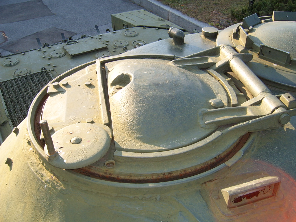
The handwheel of the traverse mechanism has a fixed gear ratio and would be the primary method of laying the machine gun on target in the horizontal plane, but it is light and coarse enough that the cupola could be traversed rapidly with it. Even with the KPVT being mounted directly to the cupola instead of a pintle combined with the loader's hatch acting as a counterweight when it is opened, the cupola is slightly unbalanced due to the huge weight of the KPVT and its ammunition box, so the handwheel is a basic necessity if the tank is on a slope. A manned KPVT on the loader's cupola of a T-10M can be seen in the photo below, taken during Operation Danube in 1968.

The Object 268 featured an identical loader's cupola on the roof of its casemate, and a brief overview of the cupola sans the KPVT can be seen in this video clip from an episode of "The Chieftain's Hatch".
A major drawback of the new cupola design was decreased size of the hatch opening, making it more difficult for the loader to ingress and egress through the hatch, especially when wearing winter clothing or when carrying some equipment on his person. The photo below, taken from from "T-10 Heavy Tank and Variants" by James Kinnear and Stephen Sewell, shows the loader's station through his open hatch.

The T-10 series carries a load of 30 rounds of ammunition, which is slightly more than the 28 rounds carried in an IS-2 or an IS-3. A substantial portion of this ammunition load was stowed in the turret.
The work of the loader is aided rather than hampered by the division of the cartridges into two parts. For reference, a unitary 122mm AP cartridge of equivalent ballistic characteristics to the existing two-part ammunition of the D-25 series of guns would have a length of 1,211mm. Individually, a case with a length of 784mm and an AP projectile with a length of 419mm are both much easier to handle than a unitary cartridge in the confines of the tank. The Conqueror and the M103 both used two-part ammunition for the same reason.
SEMI-COMBUSTIBLE PROPELLANT CHARGES
Since the D-25T and M-62T2 both use cased ammunition, the loader must deal with the hassle of occasionally disposing of spent shell casings during or after combat. This was also a problem for the M103 and Conqueror, but not the future Chieftain main battle tank which made use of lightweight bagged charges.
To achieve a further increase in the rate of fire, the development of tank ammunition with semi-combustible propellant charges in the Soviet Union began in 1954. Comprehensive testing began in 1955 on IS-3 and T-10 tanks and continued for four years, culminating in the acceptance of the new technology in 1957 and the order to begin production of semi-combustible propellant charges for 122mm HE-Frag and AP ammunition in 1959. Modified ammunition racks and fire protection equipment were approved for installation in the IS-3 and T-10 shortly afterward, and fielded to active tank units in 1961. Future ammunition developed for both the IS-3 and T-10 like HEAT and APDS rounds were only supplied with semi-combustible propellant charges, as metal-cased ammunition had been all but phased out by that point.
Combustible pyroxylin-cellulose textile impregnated with TNT was used to construct the combustible casings of the new propellant charges for the D-25T. The combustible cases were very hard and could withstand cuts and impacts, but not to the same extent as a metal casing, and of course, the combustible cases will begin to burn when subjected to an open flame for a few seconds whereas a metal casing does not burn at all. The purpose of having a rimmed steel casing stub was to ensure that the semi-combustible charges could be used in guns with a breech designed to operate with cased propellant, which would have been impossible with fully combustible charges.
The use of semi-combustible propellant charges made the loader's job easier as they were lighter to handle and there would be no need to dispose of spent casings even after long periods of sustained firing as the obturator stubs are several times shorter than a full metal casing. For the 122x785mm and 122x759mm caliber cartridges, a casing stub is a fifth of the length of a full-sized casing. The volume in the tank occupied by spent casings after each shot would be much lower accordingly and they are much easier to throw out of an open hatch. According to the study "Автоматизация Удаления Гильз Из Боевого Отделения Танка" published in 1963, creating a special space in a tank for stowing 40 full-sized spent shell casings for a hypothetical tank shell cartridge would require a hypothetical volume of 1,000 liters (1 cu.m) whereas 40 casing stubs for semi-combustible rounds of the same caliber would occupy a volume of only 200 liters.
Furthermore, according to Soviet data obtained during the development of semi-combustible propellant charges, it was shown that the substitution of metal-cased cartridges with cartridges using this type of propellant charge had the effect of reducing the concentration of propellant fumes in the fighting compartment by 60%. The combination of the light weight of the semi-combustible charges, small size of the casing stubs and the greatly reduced pollution of the fighting compartment atmosphere from propellant fumes meant that the job of the T-10 loader became much easier and the fighting efficiency of the crew as a whole saw a general improvement. Additionally, the substitution of large brass cases with small steel stubs was economically beneficial. These factors were noted to be the main advantages of semi-combustible charges in the book "Танки и танковые войска" published by the Воениздат (Voenizdat) in 1970.
British engineers were also experimenting with this type of technology around the same time as their Soviet counterparts, leading to the introduction of light bagged charges for the L11 gun of the Chieftain in the mid to late 1960's. The benefits of semi-combustible propellant casings extended to unitary cartridges as well. For example, a unitary DM12 (105) or M456 HEAT cartridge for the L7 and M68 with a brass casing weighs 21.8 kg whereas a DM12 (120) or M830 HEAT cartridge for the Rh 120 and M256 is barely heavier with a weight of only 24.2 kg despite the large increase in caliber, and this is thanks to the change from brass casings to combustible nitrocellulose casings. However, the use of semi-combustible propellant charges was not the only method of reducing the amount of clutter in the loader's station from spent shell casings while also reducing the concentration of propellant fumes. The Conqueror and the T-62 both solved these two issues by using an automatic spent shell casing ejection mechanism. When combined with a fume extractor and a good ventilation system, the concentration of propellant fumes could be reduced to nearly 0%, but the downside to this solution is that nothing is done about the greater weight of the metal-cased cartridges.
On the basic T-10 model with the D-25TA cannon, the inclusion of a ventilator intake fan on the turret ceiling above the gun breech was necessary due to the lack of a fume extractor on the D-25TA. When the D-25TS was introduced on the T-10A, the ceiling ventilation fan was omitted as it had become redundant and it slightly weakened the turret roof as it was essentially just a large hole.
The work done by the engineers at the NII-6 research bureau with the participation of the in-house design bureaus of various tank factories culminated in the universal implementation of caseless ammunition for all subsequent Soviet tanks and tank guns in the mid-1960's including the 115mm 2A21 for the T-62 and 125mm 2A26 (2A46) for the T-64A, T-72 and T-80.
Tanks that were to be supplied with the new semi-combustible ammunition required modified ammunition racks. The new racks had to be slightly narrower so that the charges did not constantly rattle around or rub against the clips, causing wear and tear by friction. The installation of new ammo racks was a very straightforward process that could be carried out during normal maintenance checkups.
AMMUNITION STOWAGE
T-10
Due to the large weight of 122mm projectiles, they are mostly stowed in the turret so that the loader does not have to bend down and exert additional effort to lift them up to the cannon breech, and the majority of the much lighter propellant charges are stowed in the hull. This also has the benefit of reducing the likelihood of an ammunition fire as the propellant charges are much more sensitive to open flames as well as impact detonation from fragments, so placing a larger share of the charges in the hull behind the tank's thickest armour where they are less likely to be damaged is generally a good idea, although the stowage layout is not optimal from a safety standpoint as the number of propellant charges stowed in the turret is non-trivial. In this sense, the T-10 is actually a step backward from the IS-3 and IS-2, both of which carried a large number of projectiles in the turret but no propellant charges. In fact, the IS-2 carried all 28 projectiles of its full ammunition load in the turret bustle. This shortcoming of the T-10 is mainly due to the short length of its turret bustle.
The British Conqueror and Chieftain tanks (both use two-piece ammunition) were also designed with the same safety considerations, but the M103 does not follow this convention as the propellant charges are stowed together with the projectiles in the turret bustle. Interestingly enough, this was repeated in the M48, M60 and M60A1 tank designs which also stowed a large quantity of their unitary ammunition in the turret.
Overall, the ammunition layout in the T-10 is imperfect but it lacks any major flaws that might impede the loader's work. On the T-10A and T-10B, the turret traverse drive is suspended after every shot until the loader presses his safety switch so that there is no chance of the loader being endangered by unexpected turret movements while he is retrieving ammunition from various racks in the hull.

A vertical rack for six projectiles is arranged in a row at the front of the turret, next to the coaxial machine gun. These are the same racks as the distinctive type found in the IS-3 turret. These racks hold projectiles in folding trays that are designed to be folded flush against the curved turret wall when not in use so as to not obstruct the loader. When the loader wishes to retrieve a projectile, he simply pulls a lever and the tray folds out, allowing the heavy projectile to slide out. This process is shown in the GIF below, created using this video from the "Cross Porcupine" channel. If the GIF loads too slowly, it can be viewed separately here.

A potential issue with the front turret projectile racks is that a non-perforating hit from a sufficiently powerful cannon could create a bulge on the back surface of the turret wall or even cause spalling. This would not set off the projectile, but the damage could render it unsafe to fire and the racks may also be knocked open, possibly causing the projectile to drop to the floor and cause a nuisance.

Two more projectiles are stowed on the turret ring underneath these vertical racks.
Ten propellant charges are placed vertically on the front right quadrant of the rotating floor.
As shown in the factory drawing below, the vertical ammunition racks take up almost half of the space on the rotating floor on the loader's side of the turret. The presence of these racks may make it impossible to access the front right hull ammunition racks when the turret is facing the front. Once these vertical ammunition racks are expended, the full length of the turret floor is freed up for the loader and the internal volume of the loader's station increases accordingly.

Several boxes of ammunition for the coaxial 12.7mm machine gun are stored on the rotating floor of the turret, underneath the main gun. Since the vertical ammunition racks on the rotating floor in front of the loader prevent him from reaching these boxes, the loader must have at least depleted the ammunition racks before being able to access this location.
Six propellant charges are clipped to each of the sponsons on the sides of the hull.
T-10M

The loader is provided with a seat attached to the rotating floor. The seat is vertically adjustable by sliding it up and down the seat post and it can also be adjusted between two horizontal positions. The first position places the seat directly underneath the loader's hatch and allows the loader to sit facing the front of the tank. The second position places the seat forward of the loader's hatch and allows the loader to easily load the cannon while seated. The grooves for sliding the seat post horizontally on the mounting point is clearly shown in the drawing below. The simple mechanism for adjusting the seat vertically is also shown. When adjusted to its full height and positioned underneath the hatch, the loader can stand on the seat to operate the anti-aircraft machine gun on his cupola, and if the seat is not needed or wanted, it can be dismantled and stowed away.

Like the T-10A and T-10B models with the "Uragan" and "Grom" stabilizers, the T-10M with the "Liven" stabilizer will automatically elevate the M62-T2 cannon by 3 degrees after each shot and fix it in place by hydrolock, thereby lowering the breech by 3 degrees from the loader's perspective. With the gun fixed at this angle, it it easier for the loader to load the cannon, especially if the tank is moving. In this condition, the stabilizer limits the maximum traverse speed of the turret to just 5 degrees per second. This helps to ensure the loader's safety from unexpected turret movements while he is retrieving ammunition from the hull.
Four ready boxes of ammunition were provided for the KPVT coaxial machine gun. One box would be placed next to the machine gun itself, ready to feed, and the other three boxes were stowed in three different locations in the fighting compartment. One box is placed in the rear right corner of the hull next to the engine compartment firewall, one box is placed in front of the front right 122mm ammunition rack, and one box is placed in front of the front left 122mm ammunition rack. If the turret is facing to the right or to the rear, only one of the boxes can be reached by the loader. Otherwise, two of the boxes can be accessed by the loader from his station.
Five ready boxes of ammunition were provided for the KPVT anti-aircraft machine gun. One box would be placed next to the machine gun itself, ready to feed, one box would be stowed externally on the turret next to the loader's cupola, and the remaining three boxes would be stowed on the turret floor. One box is placed underneath the commander's seat and two boxes are placed underneath the main gun, on top of the sealed zinc boxes of reserve ammunition. Except for the box underneath the commander's seat, all of the ammunition is accessible to the loader who is responsible for manning the anti-aircraft machine gun.
Depending on the situation, it may be expedient to use the ammunition boxes for the anti-aircraft machine gun to feed the coaxial machine gun as the coaxial is likely to see more frequent use.
The assisted loading system was retained on the new M62-T2 cannon but the ammunition stowage layout in the tank was revised. Like previous T-10 models, the loader can perform his duties while seated because the ready racks for the 122mm rounds are in the turret.

Seven projectiles are stowed in a single row along the entire length of the turret bustle. The projectiles are angled away from the loader for his convenience when retrieving them from the bustle racks. When the loader extracts a projectile from these racks, his left hand would be on the base of the projectile to pull it out and his right hand would be holding the tip. The loader could then turn on the spot and immediately lay the projectile on the ramming tray without needing to turn it around in his hands to align it with the cannon. The photo on the left below (from "T-10 Heavy Tank and Variants" by James Kinnear and Stephen Sewell) shows the rear bustle racks from the perspective of the cannon breech, and the photo on the right (credit to Stefan Kotsch) below shows the racks from the commander's perspective.


There is also a row of nine projectiles stowed facing down around the turret ring behind the casing deflector of the cannon breech guard. The nine projectiles are stowed in three separate racks mounted on the perimeter of the turret ring on rollers. Once the rack closest to the loader is expended, he can push it out of his way and pull the next rack over to his position, possibly with the commander's help. This gives the loader a consistent source of ready ammunition at the most convenient position.


There is also a row of nine projectiles stowed facing down around the turret ring behind the casing deflector of the cannon breech guard. The nine projectiles are stowed in three separate racks mounted on the perimeter of the turret ring on rollers. Once the rack closest to the loader is expended, he can push it out of his way and pull the next rack over to his position, possibly with the commander's help. This gives the loader a consistent source of ready ammunition at the most convenient position.

In total, sixteen projectiles are stowed in the two turret racks at the rear of the turret in convenient racks. Once the turret racks are fully expended, he can replenish them using the projectiles stowed on the hull floor.
For the propellant charges, the loader mainly draws from the supply of charges stowed in the turret bustle of which there are six, and on the turret wall, of which there are two. There are another seven propellant charges in the front right hull rack arranged in two staggered columns and there are six more charges in the right hull sponson. In total, twenty two propellant charges are readily available to the loader in various hull and turret racks, but the most convenient ones are the eight charges stowed in the turret.
During the initial burst of fire with the M62-T2, the loader takes eight projectiles and eight propellant charges from the turret. To load the remaining eight projectiles in the turret, the loader must take propellant charges from the turret floor and front hull racks in front of him, or from the propellant charges clipped to the sponsons. Because each ammunition type must be paired with a proprietary propellant charge, any of the three propellant charge racks may have to be used. The other four rounds that are readily available are taken from the front hull racks. The remaining eight rounds consist of eight propellant charges on the port side of the hull, but there are only five projectiles stowed in this side of the hull. The other three projectiles must be taken from the turret floor.
It is worth noting that it is possible for the tank commander to load the cannon without leaving his station thanks to the relatively large number of rounds stored near him, although he does not have the assistance of the powered rammer as the mechanism is on the loader's side of the turret. This is a rather minor advantage that would probably never have much effect except in emergency situations, but it is interesting to point out nonetheless.
LOADING ASSISTANCE DEVICE

The loading assistance device in the T-10 traces its roots to an idea by Kotin after personally trying to load 122mm shells in an IS-2 in the field after interrogating the tank crews. In Zhozef Kotin's biography "Конструктор боевых машин" (Designer of War Machines) by N. Popov and M. Ashik et al., it is reported that Kotin claimed in a 1977 interview with the "Военный вестник" magazine (Military Herald) that he made it a personal policy to follow the deployments of his new heavy tanks to the frontline in order to inspect them after battle, and this led to his personal revelation that the 122mm shells of the IS-2 (then known provisionally as the IS-122) were too heavy and a mechanical rammer was needed to assist the tank loader. Here is the relevant paragraph from the book, reprinted verbatim:
"У меня выработалось твердое правило: с каждой новой или модернизированной машиной самому выезжать на фронт, - рассказывал Ж. Я. Котин корреспонденту журнала "Военный вестник" в 1977 г., - в атаку, правда, я свои танки не водил. А вот по горячим следам, сразу же после боя, надо было посмотреть, как работает новая конструкция, побеседовать с командирами экипажей, механиками-водителями. Такая связь с фронтом давала нам очень многое. Помню, испытывался ИС. Пушка на нем стояла 122-мм. Снаряд тяжелый. Члены экипажей жалуются, что слишком много времени и сил тратят на заряжание. Полез сам в танк, попробовал подать снаряд и убедился: надо что-то делать. На заводе в срочном порядке изготовили специальное приспособление для подачи снарядов в казенную часть…"
Translated:
“I have developed a firm rule: to go to the front with each new or modernized machine myself, " - Zh. Ya. Kotin told a correspondent of the Military Herald magazine in 1977 - "I didn’t drive my tanks, though. I was hot on their heels. Immediately after the battle, it was necessary to see how the new design works, to talk with the crew commanders, the driver-mechanics. Such communication with the front gave us a lot. I remember testing the IS. The gun had a 122mm caliber. The shell was heavy. Crew members complain that too much time and effort was spent to load them. I climbed into a tank, tried to lift a shell and found it was really heavy: I needed to do something. The factory urgently produced a special device for feeding shells into the breech ... "
This special device was not fitted to the IS-3 and IS-4 in serial production, but it was reportedly tested as early as 1944 on IS-2 tanks but was rejected for unknown reasons. A loading assistance device was tested in an IS-3 with positive results and a recommendation for service, but it was never fitted to IS-3 tanks. The IS-7 had a highly automated loading system in its turret bustle akin to that of the AMX-13, and naturally, the experience gained from developing this loading system influenced the direction taken by future designers. One of the findings was that the original pneumatic rammer in the IS-7 loading mechanism was unreliable, so it was replaced by a mechanical rigid-chain rammer. This later became standard on all Soviet tanks with assisted loading mechanisms and automatic loaders even until now.
After a great deal of development and testing on various platforms over several years, loading assistance devices eventually became a standard feature among Soviet tanks with large caliber cannons beginning with the T-10.
Comparing the T-10 with the Conqueror and the M103, the T-10 is the only one that successfully implemented a powered loading assistance system of any kind. An early prototype of the Conqueror was originally intended to have an autoloader for its 120mm gun but this was scrapped before the tank entered series production, leading to the final tank having only one human loader. On the other side of the pond, the M103 was originally intended to have one loader assisted by a power-loader mechanism in the early stages of its development, but this idea did not come to fruition and the tank was designed to have two human loaders instead. The Soviet Union probably took the lead simply because Kotin had been working on this concept since the late stages of WWII, so there was more time for testing and refinement.
One of the most attractive characteristics of the T-10 loading assistance device is its compactness. The device is installed behind the cannon breech, inside the recoil guard which is mounted to the gun mounting cradle. Due to its relatively small size and narrowness, it does not intrude significantly into the loader's space or interfere very much with his work, and it also acts as a recoil guard because it physically separates the loader from the path of the recoiling cannon. The photo on the left below shows the device in a T-10M, taken from "T-10 Heavy Tank and Variants" by James Kinnear and Stephen Sewell. The image on the right below, from "Отечественные Бронированные Машины 1945-65 гг.", shows the device already present on the D-25T of the IS-5.


D-25TA, D-25TS

The loading process for the D-25TA and D-25TS is not more complex than a completely manually-loaded tank gun without assistance. On the contrary, the presence of the loading assistance device enables the loader to bypass what is usually the most physically demanding part of his job. Considering that the mass of an OF-471 HE-Frag shell is 25.25 kg and the propellant charge weighs 16.55 kg for a combined weight of 41.8 kg (92 lbs), ramming the full cartridge into the cannon chamber by hand is no mean feat, especially since the loader must also ensure that he rams the cartridge forcefully enough that the projectile engages the forcing cone in the chamber. By implementing a loading assistance device, the T-10 could fire at a higher rate than its NATO counterparts and sustain its higher rate of fire for a prolonged period of time. This was complicated by the lack of a fume extractor on the original T-10 model as sustained fire at a high rate will eventually flood the fighting compartment of the tank with fumes even with a powerful ventilator fan installed directly over the gun breech. This would not have been a problem for any T-10 model after the original.

The loading assistance device is mounted on a rail and includes a powered chain rammer, the electric motor for the rammer, a microswitch, a loading tray, a handlebar underneath the tray, and a return spring. The rigid chain for the ramming mechanism is stored in a special container underneath the tray, as shown in the drawing below. The powered chain rammer has a rubber-padded tip that contacts the base of the projectile or propellant casing. When loading, the chain rammer is programmed to actuate in two different stroke lengths - when ramming projectiles, the entire length of the chain rammer unfurls and the rammer pushes the projectile deeply into the chamber to engage with the forcing cone at the throat of the barrel in a long stroke.

When ramming propellant charges, the chain rammer only unfurls partially to push the charge into the chamber in a short stroke, due to the much shorter travelling distance. In the latter case, the much shorter stroke length takes much less time to complete and minimizes the delay before the gunner can fire the cannon. The loading assistance device slides along the rail it is mounted upon and the handlebar underneath the tray contains the stopper that locks the device in one of two positions: the "ramming" position directly behind the gun breech and in the "ready" position behind and to the right of the gun breech.

An MU-431 electric motor serves as the drive unit for the chain rammer. The motor has a power of 400 W and a torque output of 0.78 Nm which is amplified through a worm gear in the rammer unit gearbox. The 122mm 2A31 howitzer of the 2S1 "Gvozdika" and the 152mm 2A33 howitzer of the 2S3 "Akatsiya" which entered service later in 1970 and 1971 respectively both use the same MU-431 motor and have very similar loading assistance devices.
The device is normally in the "ready" position before loading and when not in use. The loader can switch the operating mode of the loading assistance device between the Automatic and Manual modes. The loader is provided with a control box mounted on the recoil guard of the cannon just next to the opening for the breech block. It can be seen in the drawing on the left below. Referring to the drawing on the right below, the control box has a button for activating the chain rammer for loading a propellant charge (labeled КД) and two signal lights, one to indicate that the system is operating in the manual mode (Р) and one to indicate that the system is operating in the automatic mode (А). When operating in the manual mode, a cover (5) above the signal lights is lifted and two buttons are available to control the chain rammer. There is a button to command the chain rammer to ram a full stroke (КПХ) and a button to command the chain rammer to recede (КОХ). A safety and instruction guide is screwed onto the cover of the control box.


Before loading the cannon, the loader must ensure that the operating mode of the loading assistance device is switched to the "automatic" setting during normal operation. The signal light (А) will be lit, informing the loader that the system is operational and the cannon is ready to be loaded.
To load, the loader receives the order to load a specific type of ammunition from the commander and he proceeds to locate a shell of the desired type. He retrieves it and deposits it on the loading tray. Then, he grasps the handlebar underneath the loading tray and pulls it back to unlock the stopper from the "ready" position, and then he proceeds to shove the unlocked device behind the breech until it is locked in place by the stopper, indicating that it is in the "ramming" position. This action tensions the return spring and it trips a microswitch which signals the powered chain rammer to begin pushing the projectile in the gun. The rammer extends a full stroke to ram the projectile all the way down the chamber.

Immediately after moving the loading assistance device into position, the loader locates and retrieves a propellant charge corresponding to the desired ammunition type. By the time the loader has retrieved a propellant charge, the mechanism would have finished the ramming cycle for the projectile. When placing the propellant charge on the freshly vacated loading tray, the loader should ensure that the base of the charge is in contact with the rubber-padded tip of the chain rammer, although it is by no means mandatory. To complete the loading procedure, the loader presses the "ram" button (marked "Досылка") on the control box, whereby the device sends the chain rammer to perform a short stroke to ram the propellant charge into the chamber. Once the rim of the propellant charge trips the casing ejector and unlocks the breech block, allowing it to close, the unlocking of the breech block also releases the stopper for the loading assistance device and it is immediately pulled back to the ready position by the return spring.
Then, the loader presses his safety button on the side of the gun breech assembly. This completes the electrical firing circuit and unblocks the mechanical firing mechanism and signals to the gunner that the cannon is ready to fire. The green light on the loader's control panel is shut off and the red light is turned on, indicating to the loader that the cannon is ready to fire.
A demonstration of the loading procedure is shown in the two short clips below. The clip does not show the loader pressing his safety button.

If there are any issues with the loading assistance device or if there is simply a loss of electrical power, the loader can immediately proceed to load the cannon manually in the usual manner. The loading assistance device does not block the loader's access to the gun chamber opening and the breech block mechanism can work independently from the device. If electrical power is available but a malfunction has occurred with the loading assistance device, the loader must switch the system to the "Manual" operating mode before attempting to load the cannon. The signal light (Р) will be lit to indicate that the system is operating in the manual mode. This allows the loader to take advantage of some of the features which can be helpful even in a degraded capacity.
If using the device manually, the loader can control the chain rammer with the buttons on his control box. He can place the projectile on the tray and shove the tray behind the gun breech as usual, and then he must open the flap on the control box and press the ram button (КПХ) to command the rammer to ram a full stroke. After this, he presses the "recede" button (КОХ), and while the chain recedes, he retrieves a propellant charge. Upon placing the propellant charge on the tray, he presses the "ram" button ("Досылка") to command the rammer to ram a short stroke. The rest of the process - including the recession of the chain rammer - is automatic.
It is worth noting that it is strictly necessary to ram the projectile and propellant charge separately, instead of positioning a projectile at the mouth of the chamber and then ramming it together with the propellant charge in a single stroke. This is due to the fact that the mouth of the propellant case is not capped with a rigid load-bearing cork, and pushing the base of the projectile by the mouth of the brass case may deform its thin walls, potentially causing it to split when the round is fired. Moreover, doing so does not shorten the loading time, because the process of ramming the projectile occurs in parallel to the loader picking up the propellant charge anyway.
The same system was carried over to the D-25TS, but some modifications were added to enable the loader to load the cannon safely while the tank is on the move with the stabilizers active. With the implementation of the PUOT and PUOT-2 stabilizers, the cannon would no longer remain fixed relative to the tank while the tank moved across rough terrain. Instead, when the tank oscillates from the movement, the cannon would remain level thanks to its vertical stabilizer, but from the loader's perspective as a passenger in the tank, the cannon is constantly elevating and depressing. To ensure that accidents do not occur during the loading process, a safety system was added.
The loader's safety system was designed to automatically disconnect the electric firing circuit and mechanical firing mechanism of the gun as well as to command the stabilizer system to cease the stabilization of the gun beginning from the moment of the shot until the end of the loading process when the loader's safety button (marked '3') is pressed by the loader to signal that a round has been loaded and that he is clear of the recoil path. Before beginning to load the cannon for the first shot, the safety switch has to be toggled manually, but the system automatically activates for every shot thereafter. The safety system will detect that the firing of a shot from the main gun has occurred by sensing the recoil stroke of the cannon using a lever switch (marked '4') attached to the loader's safety control box that maintains contact with the gun breech via a roller. When the cannon recoils, the roller rides over a special bump on the breech and this deflects the lever switch.


The electrical and mechanical firing mechanisms can also be disconnected manually without relying on the recoil sensor. To do this, the loader flips the toggle switch (marked '5') on the side of the safety system box.
M62-T2

The loading assistance device on the M62-T2 is almost completely unchanged from the D-25TS, most notably retaining the loader's safety system to return the cannon to the stabilized mode once the loading process is complete. Some minor differences include the change to a new loader's control box and the relocation of this new box to the top part of the recoil guard above the M62-T2 breech block opening. This was needed because the KPVT coaxial machine gun mounted to the M62-T2 was so long that the back of its receiver almost reached the breech block opening on the side of the breech assembly, making it impossible for the control box to remain in its original location.

On the bright side, the revised ammunition stowage layout in the T-10M helped improve the ease of loading the M62-T2. Moreover, the weight issue was only valid for the first few years of the service career of the T-10M as the situation with the increasing weight of the ammunition was ameliorated when semi-combustible propellant charges were introduced in 1961. The brass-cased 4ZhN4 charge for the OF-472 round and the brass-cased 4ZhN3 charge for the BR-472 round were replaced with the semi-combustible 4Zh14 and 4Zh15 propellant charges respectively, with the new 4Zh15 charge weighing only 14.77 kg and the 4Zh14 charge weighing only 14.6 kg. The 3VBK-5 HEAT round from 1964 and 3VBM-4 APDS round from 1967 were both fielded with semi-combustible propellant charges and never had brass casings, and the APDS cartridge was particularly light, weighing only 22.7 kg in total.
Compared to a tank where the cannon is completely manually loaded, the number of steps in the loading procedure in the T-10 is not fewer, but the mechanization of the most physically demanding parts of the procedure enables the loader to carry his duties out more rapidly and the reduced rate of exertion makes it possible to sustain a high rate of fire for prolonged periods. It would also eliminate the need to give special physical training to new recruits selected to be loaders.
It should be possible for a T-10 loader to consistently load a round in less than 10 seconds sustain this rate for a few minutes until the ready racks are completely emptied, and the sustained loading speed using all ammunition racks should be less than 15 seconds, including the time needed to turn the turret to access certain ammunition racks. Based on the official figures, the combat rate of fire (using all ammunition racks) is 3-4 rounds per minute. Under the same criteria, the IS-2 could achieve a combat rate of fire of 2-3 rounds per minute but could actually achieve a maximum rate of fire of up to 5-6 rounds per minute.
For reference, it should be noted that the 2S1 "Gvozdika" self-propelled howitzer had a very similar loading assistance device that worked identically to the one in the T-10, but with minor differences related to the vertically-sliding breech block of the 2A31 howitzer and the need to load the cannon when it is elevated at high angles for indirect fire. The loading process in a "Gvozdika" is briefly demonstrated in this clip from a show by TV Zvezda. Adding on to that, this video by a Ukrainian artilleryman during combat and this video by a Russian artilleryman during live fire training shows the loading process being carried out by real loaders under relatively relaxed conditions. Of course, it should be pointed out that the different pace of the sustained fire and different fire control procedure for artillerymen invalidates the use of the combat rate of fire of "Gvozdika" howitzers as a surrogate for the T-10 and the internal space provided for the loader is not comparable at all.
The November 2012 edition of the "Отечественные Бронированные Машины 1945-1965" series of articles authored by M.V Pavlov and published in the "Техника И Вооружение" magazine, pages 57-58, states that the IS-3 could be reloaded in an average time of just 9.5 seconds during testing with a well-trained loader at the NIIBT proving grounds when using all the ammunition racks in the tank. This figure excludes the time taken by the loader to expel a shell casing from the tank, the time taken for the gunner to lay the gun, and the time taken during the firing of the cannon itself. With all factors included, the average time between shots was 16.5 seconds for an average aimed rate of fire of 3.6 rounds per minute. Normally, these actions are only included in the reported figures for foreign tanks when evaluating the sustained rate of fire. For example, in the report "Motion Studies of German Tanks", the British Army did not include the disposal of spent casings in any of their evaluations of tank loading speeds and the rate of fire figures given in the report have been erroneously compared with the official figures listed for Soviet tanks. Essentially, a maximum short term (burst) rate of fire figure would be compared with a sustained rate of fire figure, and the results would invariably favour the foreign tanks.
A further increase could have been achieved if the IS-3 loader simply neglected to dispose of spent shell casings after every shot, and in a realistic combat scenario, the loader would only need to use ammunition from the ready racks as a single engagement rarely lasts long enough for the entire ammunition load of the tank to be expended. The disposal of spent casings is a more contentious issue when evaluating the average aimed rate of fire as tank has a ventilation fan but the D-25T does not have a fume extractor, so the fumes from the unburnt propellant residue inside the cases will accumulate with the fumes entering the fighting compartment from the cannon and eventually the toxicity of the air will reach an unacceptable level. This could be alleviated in the IS-3 by keeping the loader's hatch open, but ideally, the loader should find any chance to discard shell casings after a burst of fire. The need to dispose of spent casings was never solved in the IS-3 or in the Conqueror and M103, but it was solved in the T-10 when semi-combustible ammunition became available.
All in all, the maximum combat rate of fire of an IS-3 would be around 5-6 rounds per minute when using all ammunition racks. Furthermore, it was noted in the article (p.57) that a further increase in the aimed rate of fire of the IS-3 could be achieved by the mechanization of the loading process. Given that the T-10 features a loading assistance device and has a larger turret with more room for the loader, it is guaranteed that the actual aimed rate of fire will greatly exceed the 2-3 rounds per minute figure listed in the manual and other publications even without a well-trained loader.
It is very likely that the maximum rate of fire of a T-10 reaches or even exceeds 5-6 rounds per minute and the sustained rate of fire exceeds the 3.6 rounds per minute of the IS-3, but even with the loading assistance device on the D-25TA to reduce loader fatigue, the sustained rate of fire may still not be as high as the average aimed rate of fire as the loader in a T-10 still has to dispose of spent casings due to the lack of a fume extractor on the D-25TA. The loader in a T-10A or T-10B would have much more leeway in this regard as a fume extractor is present on the D-25TS, and all of these problems were eliminated when semi-combustible ammunition began to be supplied in 1961. The revised ammunition layout in the T-10M may contribute to an even higher rate of fire.
It is worth noting, however, that as a result of the first gamut of live gunnery trials carried out on the IS-5 in 1950, it was found that the rate of fire when using the entire ammunition load of the tank using the loading assistance device was around 1.5 times higher than with purely manual loading. The T-10 differed from the IS-5 in many ways, but not in any way that invalidates this comparison as the loader's station was functionally dentical: the gun was the same D-25TA, the ammunition layout was the same, the seat was in the same location, and so on.
With that said, the significance of these developments can be difficult to grasp without a reference point, so once again, a comparison with the Conqueror and the M103 is warranted. The main advantage of the Conqueror was that it predominantly fired APDS against armoured targets. Since APDS projectiles are much lighter than full caliber AP projectiles, the loader's burden was slashed accordingly. A secondary advantage was that it had the Mollins casing ejection device that automatically disposed of spent shell casings through a small porthole in the right side of the turret, behind the gunner's station. The ejection mechanism was automatic so the loader did not need to be involved at all, but one of its many disadvantages is that the ejection process took around 5 seconds and the mechanism itself was infamously unreliable.
Rob Griffin writes in "Conqueror" that the maximum rate of fire obtained during actual trials was 4 rounds per minute if the Mollins casing ejection mechanism was operational, but the rate of fire declined after a few minutes as the ready racks were depleted. Griffin reports that the initial requirement for the Conqueror was to be capable of firing 4 shots in the first minute, 16 rounds in 5 minutes (including the 4 shots in the first minute), and fire all 35 rounds in 55 minutes, but actual tests carried out at a gunnery range in Lulworth showed that this could not be achieved. Translated into rates of fire, the requirements were for a rate of fire of 4 RPM in the first minute, 3 RPM in the next four minutes, and an average rate of 0.38 RPM in the next 50 minutes. The tank would therefore only be required to fire 16 aimed shots in a 5-minute burst, but the fact that it could not achieve this modest firing rate at a gunnery range has extremely negative connotations on what it might achieve in combat conditions. With that said, Griffin also reported in the same book that a loading time as short as 6.5 seconds with HESH was recorded.
On the other hand, the M103 with its two loaders was able to attain a maximum rate of fire of 5 rounds per minute according to R.P Hunnicutt in "Firepower: A History of the American Heavy Tank" - a figure that is supported by Ken Estes - but the same limitations still applied; the sustained rate of fire using all ammunition racks was completely different from the burst rate of fire in the first minute alone.
As mentioned earlier in the introduction of this article, it is popularly perceived that Soviet tanks were designed with little attention to comfort or safety and that Western tanks were generally the opposite, but ironically, the loader's station in any T-10 model is objectively safer compared to its two Western counterparts the M103 and the Conqueror. In the T-10, the loader cannot be anywhere near the cannon breech when it recoils as he is physically barred by the recoil guard and the tray of the loading assistance device, whereas in the M103, there is no recoil guard at all to prevent either of the two loaders from being in the path of the recoil stroke when the cannon fires. In fact, the loaders must actually position themselves directly behind the cannon breech in order to carry out their duties, which is hardly reassuring even though there are safety systems in place. The lack of safety measures and the cramped conditions of the loaders' stations can be fully appreciated in this photo showing the interior of an M103A2 turret from the commander's perspective.
RATE OF FIRE
Compared to a tank where the cannon is completely manually loaded, the number of steps in the loading procedure in the T-10 is not fewer, but the mechanization of the most physically demanding parts of the procedure enables the loader to carry his duties out more rapidly and the reduced rate of exertion makes it possible to sustain a high rate of fire for prolonged periods. It would also eliminate the need to give special physical training to new recruits selected to be loaders.
It should be possible for a T-10 loader to consistently load a round in less than 10 seconds sustain this rate for a few minutes until the ready racks are completely emptied, and the sustained loading speed using all ammunition racks should be less than 15 seconds, including the time needed to turn the turret to access certain ammunition racks. Based on the official figures, the combat rate of fire (using all ammunition racks) is 3-4 rounds per minute. Under the same criteria, the IS-2 could achieve a combat rate of fire of 2-3 rounds per minute but could actually achieve a maximum rate of fire of up to 5-6 rounds per minute.
For reference, it should be noted that the 2S1 "Gvozdika" self-propelled howitzer had a very similar loading assistance device that worked identically to the one in the T-10, but with minor differences related to the vertically-sliding breech block of the 2A31 howitzer and the need to load the cannon when it is elevated at high angles for indirect fire. The loading process in a "Gvozdika" is briefly demonstrated in this clip from a show by TV Zvezda. Adding on to that, this video by a Ukrainian artilleryman during combat and this video by a Russian artilleryman during live fire training shows the loading process being carried out by real loaders under relatively relaxed conditions. Of course, it should be pointed out that the different pace of the sustained fire and different fire control procedure for artillerymen invalidates the use of the combat rate of fire of "Gvozdika" howitzers as a surrogate for the T-10 and the internal space provided for the loader is not comparable at all.
The November 2012 edition of the "Отечественные Бронированные Машины 1945-1965" series of articles authored by M.V Pavlov and published in the "Техника И Вооружение" magazine, pages 57-58, states that the IS-3 could be reloaded in an average time of just 9.5 seconds during testing with a well-trained loader at the NIIBT proving grounds when using all the ammunition racks in the tank. This figure excludes the time taken by the loader to expel a shell casing from the tank, the time taken for the gunner to lay the gun, and the time taken during the firing of the cannon itself. With all factors included, the average time between shots was 16.5 seconds for an average aimed rate of fire of 3.6 rounds per minute. Normally, these actions are only included in the reported figures for foreign tanks when evaluating the sustained rate of fire. For example, in the report "Motion Studies of German Tanks", the British Army did not include the disposal of spent casings in any of their evaluations of tank loading speeds and the rate of fire figures given in the report have been erroneously compared with the official figures listed for Soviet tanks. Essentially, a maximum short term (burst) rate of fire figure would be compared with a sustained rate of fire figure, and the results would invariably favour the foreign tanks.
A further increase could have been achieved if the IS-3 loader simply neglected to dispose of spent shell casings after every shot, and in a realistic combat scenario, the loader would only need to use ammunition from the ready racks as a single engagement rarely lasts long enough for the entire ammunition load of the tank to be expended. The disposal of spent casings is a more contentious issue when evaluating the average aimed rate of fire as tank has a ventilation fan but the D-25T does not have a fume extractor, so the fumes from the unburnt propellant residue inside the cases will accumulate with the fumes entering the fighting compartment from the cannon and eventually the toxicity of the air will reach an unacceptable level. This could be alleviated in the IS-3 by keeping the loader's hatch open, but ideally, the loader should find any chance to discard shell casings after a burst of fire. The need to dispose of spent casings was never solved in the IS-3 or in the Conqueror and M103, but it was solved in the T-10 when semi-combustible ammunition became available.
All in all, the maximum combat rate of fire of an IS-3 would be around 5-6 rounds per minute when using all ammunition racks. Furthermore, it was noted in the article (p.57) that a further increase in the aimed rate of fire of the IS-3 could be achieved by the mechanization of the loading process. Given that the T-10 features a loading assistance device and has a larger turret with more room for the loader, it is guaranteed that the actual aimed rate of fire will greatly exceed the 2-3 rounds per minute figure listed in the manual and other publications even without a well-trained loader.
It is very likely that the maximum rate of fire of a T-10 reaches or even exceeds 5-6 rounds per minute and the sustained rate of fire exceeds the 3.6 rounds per minute of the IS-3, but even with the loading assistance device on the D-25TA to reduce loader fatigue, the sustained rate of fire may still not be as high as the average aimed rate of fire as the loader in a T-10 still has to dispose of spent casings due to the lack of a fume extractor on the D-25TA. The loader in a T-10A or T-10B would have much more leeway in this regard as a fume extractor is present on the D-25TS, and all of these problems were eliminated when semi-combustible ammunition began to be supplied in 1961. The revised ammunition layout in the T-10M may contribute to an even higher rate of fire.
It is worth noting, however, that as a result of the first gamut of live gunnery trials carried out on the IS-5 in 1950, it was found that the rate of fire when using the entire ammunition load of the tank using the loading assistance device was around 1.5 times higher than with purely manual loading. The T-10 differed from the IS-5 in many ways, but not in any way that invalidates this comparison as the loader's station was functionally dentical: the gun was the same D-25TA, the ammunition layout was the same, the seat was in the same location, and so on.
With that said, the significance of these developments can be difficult to grasp without a reference point, so once again, a comparison with the Conqueror and the M103 is warranted. The main advantage of the Conqueror was that it predominantly fired APDS against armoured targets. Since APDS projectiles are much lighter than full caliber AP projectiles, the loader's burden was slashed accordingly. A secondary advantage was that it had the Mollins casing ejection device that automatically disposed of spent shell casings through a small porthole in the right side of the turret, behind the gunner's station. The ejection mechanism was automatic so the loader did not need to be involved at all, but one of its many disadvantages is that the ejection process took around 5 seconds and the mechanism itself was infamously unreliable.
Rob Griffin writes in "Conqueror" that the maximum rate of fire obtained during actual trials was 4 rounds per minute if the Mollins casing ejection mechanism was operational, but the rate of fire declined after a few minutes as the ready racks were depleted. Griffin reports that the initial requirement for the Conqueror was to be capable of firing 4 shots in the first minute, 16 rounds in 5 minutes (including the 4 shots in the first minute), and fire all 35 rounds in 55 minutes, but actual tests carried out at a gunnery range in Lulworth showed that this could not be achieved. Translated into rates of fire, the requirements were for a rate of fire of 4 RPM in the first minute, 3 RPM in the next four minutes, and an average rate of 0.38 RPM in the next 50 minutes. The tank would therefore only be required to fire 16 aimed shots in a 5-minute burst, but the fact that it could not achieve this modest firing rate at a gunnery range has extremely negative connotations on what it might achieve in combat conditions. With that said, Griffin also reported in the same book that a loading time as short as 6.5 seconds with HESH was recorded.
On the other hand, the M103 with its two loaders was able to attain a maximum rate of fire of 5 rounds per minute according to R.P Hunnicutt in "Firepower: A History of the American Heavy Tank" - a figure that is supported by Ken Estes - but the same limitations still applied; the sustained rate of fire using all ammunition racks was completely different from the burst rate of fire in the first minute alone.
As mentioned earlier in the introduction of this article, it is popularly perceived that Soviet tanks were designed with little attention to comfort or safety and that Western tanks were generally the opposite, but ironically, the loader's station in any T-10 model is objectively safer compared to its two Western counterparts the M103 and the Conqueror. In the T-10, the loader cannot be anywhere near the cannon breech when it recoils as he is physically barred by the recoil guard and the tray of the loading assistance device, whereas in the M103, there is no recoil guard at all to prevent either of the two loaders from being in the path of the recoil stroke when the cannon fires. In fact, the loaders must actually position themselves directly behind the cannon breech in order to carry out their duties, which is hardly reassuring even though there are safety systems in place. The lack of safety measures and the cramped conditions of the loaders' stations can be fully appreciated in this photo showing the interior of an M103A2 turret from the commander's perspective.
POWERED CONTROLS (T-10)
TAEN-1
The T-10 was outfitted with the advanced TAEN-1 automated powered gun laying system for aiming and firing the main gun and coaxial machine gun. Both the turret rotation and the gun elevation drives are electromechanical with manual backups. Naturally, the mechanical clutches of the manual turret rotation and gun elevation mechanisms must be disengaged before using the powered systems.
The system also facilitated the automatic target designation system of the TPKU periscope operated by the tank commander. When a target is detected by the commander, he places his point of aim on it and he presses the target designator button on his left cupola control handle. This overrides the TAEN-1 system so that it automatically lays the gun on the target designated by the commander in both planes. This was somewhat more sophisticated than the target designation function provided by the EPB-4 powered traverse system of the T-54 obr. 1951 as that system could only lay the gun on the target in the horizontal plane.
More importantly, the TAEN-1 system provided the gunner with full control of the gun in both planes via a single set of control handles that could produce progressive traverse and elevation speeds by changing the deflection angle of the handles. The system allowed the gunner to quickly traverse the gun onto a target like the conventional powered traverse systems found in contemporary tanks, but unlike the existing control systems at the time, the precision of the TAEN-1 gun laying drives was high enough that the final lay on both planes could be done using the powered controls. By contrast, the less sophisticated control scheme in the EPB-1 powered traverse system as found in the IS-4 and T-54 obr. 1947 and T-54 obr. 1949 only provided the gunner with the ability to use powered traverse to lay the gun in azimuth as gun elevation had to be done manually. The process of laying the gun on target was therefore much more fluid and intuitive with the TAEN-1 system than the EPB-4 system.
The gunner's control handles are placed directly below the TSh2-27 primary sight and above the manual gun elevation handwheel, as shown below. The photo is taken from "T-10 Heavy Tank and Variants" by James Kinnear and Stephen Sewell.

Gun elevation and traverse was sensed by a pair of rheostats. The maximum gun elevation and traverse speeds were attained by pushing the handles to their limits of deflection in both axes, but if the gunner desires to lay the gun on target with maximum precision, he could simply nudge the handles lightly in the appropriate direction. The minimum speed of gun laying in both axes was 0.05 degrees per second. To put this into perspective, the time needed for the turret to complete a full rotation at this speed is 2 hours.
Besides having a more sophisticated fire control system than the heavy tanks preceding it, the T-10 most likely had better firing precision when firing on the move or on short halts thanks to its bundled torsion bars. A suspension with a high damping capacity reduces the oscillations of the hull, reduces the power consumption and errors of the stabilizer, and reduces the vibration of the barrel, contributing to reduced dispersion.
Vertical:
Maximum elevating speed: 4° per second
Minimum elevating speed: 0.05° per second
Horizontal:
Maximum Turret Traverse Speed: 14.8° per second
Minimum Turret Traverse Speed: 0.05° per second
In terms of gun laying speed and precision, the TAEN-1 system was sufficient for the needs of a modern tank of the early 1950's. It was more precise than any T-54 variant as those had a minimum traverse speed of only 0.07 degrees per second compared to 0.05 degrees per second. It also provided a 48% quicker maximum turret traverse speed than the EPB-4 powered traverse system of the T-54 obr. 1951 and the STP-1 stabilizer system of the T-54A (1954), both of which were only capable of a turret rotation speed of just 10° per second. The IS-4 heavy tank used the EPB-1 powered traverse system and also had a turret rotation speed of 10° per second.
STABILIZERS (T-10A, T-10B, T-10M)
The T-10 series was consistently outfitted with the most modern stabilization systems in the USSR as they became available and there was a clear technological distinction between the fire control systems of the T-10 series and the T-54 series. Some of the most major differences are related to the higher complexity of the primary sights of the T-10 series (beginning with the T-10A). The cost of the stabilizers installed in the T-10 series was higher, but it was justified as it was proportional to the results that they were capable of producing.
By contrast, very few foreign tanks had stabilizers at the time, and of those that did, they only permitted accurate fire at short range or were limited to providing the gunner with a stable field of view without the possibility of accurate fire while on the move. The T-10 was certainly the only heavy tank that had a stabilizer. The Conqueror is interesting in this regard as it is sometimes said to have a stabilizer, but in reality it had an extremely limited pseudo-stabilization system where the gunner's controls would be automatically disengaged once the tank exceeded a speed of approximately 2 mph whereupon the gyroscopic stabilization system would activate. The system would keep the gun stable within the elevation angles of +1 to +15 degrees, and the gunner's controls would only return to action after the tank came to a full stop, and only after a delay of three seconds. During this time, the gunner could look through his sights but it would be aimed at the sky, so he would not be able to find a target let alone lay the reticle on it during the three-second interval. Of course, the gunner would have to also find the target after he regained control, so the reaction time of the tank is further extended.
Although the system incorporated a gyroscopic stabilizer and technically kept the gun "stable" within a very generous range of elevation angles, it stripped the gunner of control and prevented the armament of the tank from being used while it was active. This system also greatly hampered the Conqueror's ability to fire on short halts, rendering the tank much less effective unless it was completely static before contact with the enemy is initiated. This relied on the assumption that Conqueror commanders possessed omniscience regarding the enemy's intentions.
T-10A
PUOT "Uragan"

The PUOT "Uragan" stabilizer is a single-plane stabilizer with fully electric gun elevation and turret rotation drives. Turret rotation was fully powered but not stabilized. This complicates firing on the move, so it was still advisable to fire from a slow crawl or a short halt. With the "Uragan", the ability to accurately fire on tank-sized targets while moving at high speeds had not yet been achieved, although the use of fire gating in the stabilizer was a great step forward towards this goal. Control of the turret and gun is actuated by the TAEN-2 drive system which is controlled through the gunner's control handles, which were of a particularly ergonomic design for their time, being self-contained two-axis mechanisms with a pair of handles for the gunner's two hands like in any modern tank. This set it apart from the turret control systems of foreign tanks, which still used joysticks (Patton family, M103) or separate elevation and traverse handles (Centurion). The electric gun elevation motor is the MI-400 and the amplidyne amplifier for the motor is the EMU-3PM. It interfaces with the elevation gear on a toothed arc on the D-25TA gun - which is shared with the backup manual elevation drive - via a worm gear, which can be seen in the diagram below. Underneath the motor is the amplidyne. The electric turret rotation motor is the MI-22M and the amplidyne amplifier for the motor is the EMU-12PM.

If the stabilizer is switched from the automatic mode to the semi-automatic mode, all gyroscopic stabilization is disabled and the gunner assumes direct control of the TAEN-2 drives which only provide powered turret traverse and gun elevation. The fire control system essentially regresses to the level of the T-10. The field of view of the sight becomes directly coupled to the elevation of the gun via a parallelogram linkage, and the precision of aiming is downgraded to the level offered by the minimum movement speeds of the turret traverse and gun elevation mechanisms. As examined earlier in the section on the TPS1 primary sight, the "Uragan" system is slaved to the much more precise stabilizer of the TPS1 and the two systems are very tightly intertwined in their operation.
Unlike the conventional stabilization scheme employed by the contemporary STP-1 stabilizer of the T-54A (1955) where the weapons were stabilized at the highest possible precision and the sights are mechanically linked to the weapons so that they shared the same precision of stabilization, "Uragan" keeps the gun loosely stabilized when the tank is in motion and only maintains the orientation of the gun close to the point of aim of the TPS1 within a limit of ± 2.5 degrees. Corrections are continuously applied, but the gun is only automatically elevated at a speed of 8 mils per second (0.48 degrees per second). If the tank is pitching and diving as it is driven across undulating terrain, the loosely stabilized gun will appear as if it is languidly shifting in the opposite direction of the pitching and diving on its own as shown in the clip on the right below. A tightly stabilized gun would simply appear to be completely level even when the tank is moving at a relatively high speed on rough terrain, as the clip on the left shows on a T-54B.


When the gunner presses the firing button, "Uragan" verifies if the two systems are in alignment, at which point the gun is fired. The system guarantees that the precision of the alignment between the gun and the point of aim of the TPS1 sight is ± 0.5 mils. The time taken for the verification does not exceed one second. To minimize the lag time as much as possible, the elevation speed is temporarily boosted to 4.0 degrees per second until the gun achieves coincidence with the aim point of the TPS1 sight and the shot is fired. "Uragan" features automatic lag compensation to account to eliminate errors from this phenomenon as well as the lag between the initiation of the electric primer for the main gun cartridges and the moment that the shell exits the muzzle. The fire control system facilitates higher accuracy compared to a conventional gun stabilization scheme where only the gun is tightly stabilized and the sights are linked to the gun. When the tank is static, the gun stabilizer does not need to compensate for the deflection of the gun due to the vertical oscillations induced by movement across uneven ground, so it is able to keep the gun aligned with the point of aim of the sight at all times.
The stabilizer does not treat the coaxial DShKM machine gun the same as the cannon, mainly because the machine gun is a fully automatic weapon so it was not feasible to control the moment it is fired to the moment that its point of aim aligns with the sights. Furthermore, there was no automatic lag compensation programmed into the stabilizer to account for the lag inherent in the mechanical firing mechanism, so it is not reasonable to expect to hit point targets when the tank is moving except at short ranges. This was because the lag time between the triggering and the actual firing of the DShKM was 10 times longer than that of the cannon. If the machine gun was fired on the move using the same fire gating system as the main gun, most of the bullets would probably hit the ground in front of the target or fly clear over it. However, if the tank is cruising at a modest speed on relatively flat ground, the level of accuracy with the loose stabilization is still better than with no stabilization at all so it is possible to use the coaxial machine gun with reasonable accuracy.

If the coaxial machine gun is being used in lieu of the main gun to engage vehicles such as trucks and APCs with short bursts, it is more efficient to fire from short halts or using the semi-automatic mode of the stabilizer, i.e. regressing to an unstabilized state with powered controls.
With that in mind, the question arises as to why the stabilizer for the gun should not be discarded entirely in favour of a free-swinging gun paired with simple powered elevation or manual elevation as backups. There are a multitude of technical reasons, but the simplest is that even if the point of aim of a free-swinging gun may eventually coincide with the point of aim of the sights, it simply cannot be relied upon, not to mention that there is guaranteed to be a long lag before the shot can be fired. Furthermore, a free-swinging gun is subjected to the full amplitude of vibrations transmitted from the suspension of the tank during movement, and the pitching motion of the tank is translated into strong oscillations at the muzzle of the gun barrel. The oscillations take some time to dissipate even after the tank stops to fire, thus increasing the dispersion of shots compared to a fully static tank by several times. A free-swinging gun would also have a significant amount of vertical momentum if it is in motion during the moment of firing, as vertical momentum has a major impact on the uniformity of the recoil cycle and the vertical motion of the gun also imparts a vertical moment on the projectile before it leaves the muzzle. These factors, and several more, add up to severely degrade the accuracy of fire.
Adding on to all of this, a freely swinging gun is liable to hit the ground in front of the tank when the tank is moving on undulating terrain, and the swinging motion of the gun breech inside the turret is a safety hazard. The gun itself may also be damaged by hitting the hard stops at the limits of its elevation and depression angles. Gun stabilizers, even loose systems like in "Uragan", are effective at damping the errors incurred by having a completely free-swinging gun and ensure that it is not damaged by including braking zones at the limits of its elevation and depression.
It is particularly noteworthy that the "Uragan" stabilization scheme was the first of its kind to be implemented in mass-produced tanks in 1956 when in the U.S.A and other Western nations, such concepts had not yet progressed beyond the research stage. In the report "Tank Fire Control Systems Study: Evaluation of Some Alternative Systems of Tank Stabilization" from April 1955 by Philip I. Brown of the Fire Control Instrument Group, this stabilization scheme was referred to as the "three-switch" proposal and was shown to be the most promising system in terms of fire accuracy in theoretical models. Fundamentally, this scheme provides the highest accuracy that can be achieved from all possible gyroscopic stabilization systems. After its first appearance in "Uragan", this operating scheme was carried over to later models of the T-10 and was implemented on the T-64 (Object 432) in 1963 whereas the first instance of a Western nation managing to operationally implement such a scheme was more than two decades later with the appearance of the Leopard 2 in 1979.
At the end of 1954, three experimental T-10 tanks equipped with the "Uragan" stabilizer were delivered and on the 14th of February 1955, they were ordered to be sent for testing at the Main Research Site of the State Agrarian University. The tests ran from May 5 to June 18, 1955 and the three tanks drove a total cumulative distance of 2,752 kilometers and fired 1,503 shots.
With a maximum turret traverse speed of 14 degrees per second, the turret is appreciably quicker to rotate than the turret of a T-54A and all preceding T-54 models, all of which had a turret traverse speed of only 10 degrees per second. The maximum gun elevation speed of 3 degrees per second is somewhat ponderous, but is still acceptable. Using the stabilizer in the semi-automatic mode marginally increases the speed of elevation to 3.6 degrees per second.
When the stabilizer is operated in the automatic mode, the range of vertical elevation decreased by 30' to 45' (0.5 to 0.75 degrees) at the limits of elevation and depression in order to create braking zones. This feature was incorporated into the stabilizer to ensure that the gun does not slam into the hard stops at high speed at the limits of its elevation range when the tank is travelling across rough terrain. This came at the expense of further decreasing the extremely limited gun depression limit of the T-10A when the stabilizer was used in the automatic mode. Interestingly enough, the Conqueror heavy tank "solved" this problem by using a pseudo-stabilization system that kept the gun elevated at +1 to +15 degrees.
The stabilizer automatically places the cannon elevation into hydrolock after every shot for the loader's safety. It is unlocked when the loader presses the loader's safety button on the side of the cannon breech, signalling the stabilizer to return to the last elevation angle during the previous shot and resume normal operation with full control returned to the gunner.
Vertical (semi-automatic mode):
Maximum elevating speed: 3.0° per second (3.6°)
Minimum elevating speed: 0.05° per second
Horizontal:
Maximum Turret Traverse Speed: 14° per second
Minimum Turret Traverse Speed: 0.05° per second
The stabilizer consumes 2.5 kW of power on average during normal operation.
T-10B
PUOT-2 "Grom"

The "Grom" stabilizer offered dual-axis stabilization with the option of switching between automatic and semi-automatic modes. The stabilizer was only used in the T-10B, but the first 20 T-10B tanks had the "Uragan" stabilizer installed due to supply issues. The remaining 90 tanks produced were outfitted with "Grom".
Because the gun received a fully independent stabilization system, it became possible to fire the coaxial machine gun accurately on the move in the automatic mode. This makes it vastly more effective against point targets and it could help to improve the overall survivability of the tank as it is now possible for the driver to maneuver the tank while the gunner engages dangerous anti-tank weapons with accurate machine gun fire. This includes towed anti-tank guns, recoilless rifle emplacements, and could even include dangerous armoured vehicles like the M56 "Scorpion" and M551 "Sheridan".
The horizontal stabilizer was not slaved to the sight with a switching system like the vertical stabilizer. Instead, it works as a conventional stabilizer that attempts to keep the turret aimed at the target in azimuth with maximum precision. This was mainly due to the lack of independent horizontal stabilization in the T2S sight itself, but also because the accuracy benefit of implementing such a system for controlling turret rotation was lower than it was for the gun elevation. The stabilization precision of the PUOT-2 is 1 mil in the vertical plane and 3 mils in the horizontal plane.
The elevation drive had increased precision with a minimum elevating speed that was five times slower than the elevation drive of the "Uragan" stabilizer - 0.01 degrees per second instead of 0.05 degrees per second. The speed of the turret rotation drive was also very close to the STP-2 "Tsyklon" stabilizer of the T-54B (1956) which had a maximum speed of 15 degrees per second, and its gun laying precision was far higher.
Vertical:
Maximum elevating speed: 3° per second
Minimum elevating speed: 0.01° per second
Horizontal:
Maximum Turret Traverse Speed: 14° per second
Minimum Turret Traverse Speed: 0.05° per second
The higher electrical load due to the inclusion of a horizontal stabilizer meant that the 3 kW engine generator of previous T-10 models had to be replaced with a 5 kW generator.

The "Liven" dual-axis stabilizer was installed in the T-10M exclusively. It was more sophisticated than previous stabilization systems, eliminated previous technical drawbacks and facilitated greater accuracy. Structurally, the most major difference is that the gun elevation drive was changed from an electric mechanism to a hydraulic mechanism with a piston actuator to move the gun up and down. As before, the stabilizer could be switched between automatic and semi-automatic modes. The vertical gun stabilization system restricts the maximum gun depression angle to -4.5 degrees instead of the full -5 degrees due to the need for braking zones at the elevation limits of the gun to reduce the shock load on the gun elevation mechanism when the stabilizer is attempting to keep the gun aligned to the T2S sight while the tank moves over rough terrain. When operating in the semi-automatic mode, the maximum gun depression angle is increased to the full limit of -5 degrees as the gun is no longer stabilized, so braking zones were no longer necessary. The stabilization precision of the PUOT-2S is 1 mil in the vertical plane and 3 mils in the horizontal plane.
The addition of a high-precision vertical gun stabilizer system made it necessary to increase the output of the engine generator from 5 kW to 6.5 kW to handle the higher electrical load.
After each shot, the cannon is elevated by 3 degrees and fixed by a hydrolock in the elevator piston, thereby lowering the breech by 3 degrees from the loader's perspective. With the gun fixed at this angle, it it easier for the loader to load the cannon, especially if the tank is moving. In this condition, the stabilizer limits the maximum traverse speed of the turret to just 5 degrees per second.
Due to the high complexity of the system, the training of new cadets in the use of the T-10M was a uniquely difficult task compared to the T-55 or T-62 which lacked independent sight stabilization. For the qualitative study and development of the "Liven", powered simulator cabins to demonstrate the functions of the stabilizer were created and installed in tank schools.
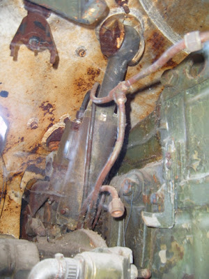
The maximum turret traverse speed of 18 degrees per second is entirely respectable for a heavy tank. This makes the turret quicker to rotate than the turret of a Conqueror which had a traverse speed of 15 degrees per second and it is equivalent to a basic M103 which had an identical maximum turret traverse speed, but it is outstripped by the M103A2 (21 degrees per second). It takes 20 seconds for a T-10M turret to complete a full rotation.
Vertical:
Maximum elevating speed: 4.5° per second
Minimum elevating speed: 0.01° per second
Horizontal:
Maximum Turret Traverse Speed: 18° per second
Minimum Turret Traverse Speed: 0.05° per second
As usual, all T-10 tanks had a set of manual turret traverse and gun elevation drives. These were worked using hand cranks and power was transmitted via worm gears. In order to use them, the stabilizer must be disabled and the mechanical clutches of both the manual turret rotation and gun elevation mechanisms must be engaged. This ensures that the only input force is from the gunner. The gun elevation mechanism is mounted to the gun cradle of the main gun and the turret rotation mechanism is mounted to the turret ring.
The elevation wheel handle has an electric thumb trigger for firing the main gun, but there is no way to fire the coaxial machine gun electrically from the gunner's station when operating in manual mode. To do this, the loader would have to manually pull the emergency trigger on the DShKM or KPVT receiver when ordered by the commander, who would be responsible for tightly coordinating the crew in such situations. If all electrical systems in the tank were to fail, the main gun can be fired by pulling the emergency trigger on the side of the cannon itself. These procedures apply for all T-10 models.

An interesting side effect of the unusual layout of the gunner's control handles on the T2S-29-14 sight of the T-10M is that a lot of space beneath the sight was freed up so there was much more room to use the manual turret traverse and gun elevation handwheels. It is doubtful if this had any real effect on the combat effectiveness of the tank, however.

With a muzzle energy of 8 MJ, the D-25T was among the most powerful guns of WWII and was still a viable weapon in the immediate postwar period, but the need for a more powerful gun was recognized at the end of WWII when new German heavy tanks and tank destroyers like the Tiger II and the Jagdtiger were captured and inspected. Soviet engineers approached the issue by attempting to create large caliber guns with an increased muzzle velocity. Work on installing more powerful guns in the latest heavy tank projects had already been underway several years before the T-10 entered service, and the 130mm S-53 was one of the options considered. The only reason for the installation of a derivative of the D-25T on the T-10 in 1953 was that other alternatives were still technologically immature. There was no real justification to actively use the D-25 in the postwar era.
The demolition power of its HE-Frag shells was still a highly persuasive argument against stubborn opposition, but the limited potential of the D-25T against heavily armoured targets made it an inefficient weapon against some of the latest medium tanks of the probable enemy, and it would have struggled against new heavy tanks like the M103 and Conqueror.
The barrel length is 5,610mm or 46 calibers. The maximum operating pressure of all guns derived from the D-25T including the D-25TA and D-25TS is 270 MPa.
The D-49 gun installed in the SU-122 casemate tank destroyer otherwise known as the "SU-122-54" was developed in parallel with the D-25TA. The two guns shared many similarities and both used the same loading assistance device. Besides the expected differences such as the different gun cradle, gun laying mechanism and the different mounts for the articulated telescopic sights, the most noteworthy difference is that the D-49 had a fume extractor. In fact, the D-49 was the first Soviet tank gun to have one.
The horizontal stabilizer was not slaved to the sight with a switching system like the vertical stabilizer. Instead, it works as a conventional stabilizer that attempts to keep the turret aimed at the target in azimuth with maximum precision. This was mainly due to the lack of independent horizontal stabilization in the T2S sight itself, but also because the accuracy benefit of implementing such a system for controlling turret rotation was lower than it was for the gun elevation. The stabilization precision of the PUOT-2 is 1 mil in the vertical plane and 3 mils in the horizontal plane.
The elevation drive had increased precision with a minimum elevating speed that was five times slower than the elevation drive of the "Uragan" stabilizer - 0.01 degrees per second instead of 0.05 degrees per second. The speed of the turret rotation drive was also very close to the STP-2 "Tsyklon" stabilizer of the T-54B (1956) which had a maximum speed of 15 degrees per second, and its gun laying precision was far higher.
Vertical:
Maximum elevating speed: 3° per second
Minimum elevating speed: 0.01° per second
Horizontal:
Maximum Turret Traverse Speed: 14° per second
Minimum Turret Traverse Speed: 0.05° per second
The higher electrical load due to the inclusion of a horizontal stabilizer meant that the 3 kW engine generator of previous T-10 models had to be replaced with a 5 kW generator.
T-10M
PUOT-2S "Liven"

The "Liven" dual-axis stabilizer was installed in the T-10M exclusively. It was more sophisticated than previous stabilization systems, eliminated previous technical drawbacks and facilitated greater accuracy. Structurally, the most major difference is that the gun elevation drive was changed from an electric mechanism to a hydraulic mechanism with a piston actuator to move the gun up and down. As before, the stabilizer could be switched between automatic and semi-automatic modes. The vertical gun stabilization system restricts the maximum gun depression angle to -4.5 degrees instead of the full -5 degrees due to the need for braking zones at the elevation limits of the gun to reduce the shock load on the gun elevation mechanism when the stabilizer is attempting to keep the gun aligned to the T2S sight while the tank moves over rough terrain. When operating in the semi-automatic mode, the maximum gun depression angle is increased to the full limit of -5 degrees as the gun is no longer stabilized, so braking zones were no longer necessary. The stabilization precision of the PUOT-2S is 1 mil in the vertical plane and 3 mils in the horizontal plane.
The addition of a high-precision vertical gun stabilizer system made it necessary to increase the output of the engine generator from 5 kW to 6.5 kW to handle the higher electrical load.
After each shot, the cannon is elevated by 3 degrees and fixed by a hydrolock in the elevator piston, thereby lowering the breech by 3 degrees from the loader's perspective. With the gun fixed at this angle, it it easier for the loader to load the cannon, especially if the tank is moving. In this condition, the stabilizer limits the maximum traverse speed of the turret to just 5 degrees per second.
Due to the high complexity of the system, the training of new cadets in the use of the T-10M was a uniquely difficult task compared to the T-55 or T-62 which lacked independent sight stabilization. For the qualitative study and development of the "Liven", powered simulator cabins to demonstrate the functions of the stabilizer were created and installed in tank schools.

The maximum turret traverse speed of 18 degrees per second is entirely respectable for a heavy tank. This makes the turret quicker to rotate than the turret of a Conqueror which had a traverse speed of 15 degrees per second and it is equivalent to a basic M103 which had an identical maximum turret traverse speed, but it is outstripped by the M103A2 (21 degrees per second). It takes 20 seconds for a T-10M turret to complete a full rotation.
Vertical:
Maximum elevating speed: 4.5° per second
Minimum elevating speed: 0.01° per second
Horizontal:
Maximum Turret Traverse Speed: 18° per second
Minimum Turret Traverse Speed: 0.05° per second
MANUAL CONTROLS
As usual, all T-10 tanks had a set of manual turret traverse and gun elevation drives. These were worked using hand cranks and power was transmitted via worm gears. In order to use them, the stabilizer must be disabled and the mechanical clutches of both the manual turret rotation and gun elevation mechanisms must be engaged. This ensures that the only input force is from the gunner. The gun elevation mechanism is mounted to the gun cradle of the main gun and the turret rotation mechanism is mounted to the turret ring.
The elevation wheel handle has an electric thumb trigger for firing the main gun, but there is no way to fire the coaxial machine gun electrically from the gunner's station when operating in manual mode. To do this, the loader would have to manually pull the emergency trigger on the DShKM or KPVT receiver when ordered by the commander, who would be responsible for tightly coordinating the crew in such situations. If all electrical systems in the tank were to fail, the main gun can be fired by pulling the emergency trigger on the side of the cannon itself. These procedures apply for all T-10 models.

An interesting side effect of the unusual layout of the gunner's control handles on the T2S-29-14 sight of the T-10M is that a lot of space beneath the sight was freed up so there was much more room to use the manual turret traverse and gun elevation handwheels. It is doubtful if this had any real effect on the combat effectiveness of the tank, however.
D-25TA, D-25TS
With a muzzle energy of 8 MJ, the D-25T was among the most powerful guns of WWII and was still a viable weapon in the immediate postwar period, but the need for a more powerful gun was recognized at the end of WWII when new German heavy tanks and tank destroyers like the Tiger II and the Jagdtiger were captured and inspected. Soviet engineers approached the issue by attempting to create large caliber guns with an increased muzzle velocity. Work on installing more powerful guns in the latest heavy tank projects had already been underway several years before the T-10 entered service, and the 130mm S-53 was one of the options considered. The only reason for the installation of a derivative of the D-25T on the T-10 in 1953 was that other alternatives were still technologically immature. There was no real justification to actively use the D-25 in the postwar era.
The demolition power of its HE-Frag shells was still a highly persuasive argument against stubborn opposition, but the limited potential of the D-25T against heavily armoured targets made it an inefficient weapon against some of the latest medium tanks of the probable enemy, and it would have struggled against new heavy tanks like the M103 and Conqueror.
The barrel length is 5,610mm or 46 calibers. The maximum operating pressure of all guns derived from the D-25T including the D-25TA and D-25TS is 270 MPa.
The D-49 gun installed in the SU-122 casemate tank destroyer otherwise known as the "SU-122-54" was developed in parallel with the D-25TA. The two guns shared many similarities and both used the same loading assistance device. Besides the expected differences such as the different gun cradle, gun laying mechanism and the different mounts for the articulated telescopic sights, the most noteworthy difference is that the D-49 had a fume extractor. In fact, the D-49 was the first Soviet tank gun to have one.
To remove or install the gun, the turret is unbolted from the turret ring platform and then its front is raised with a crane until there is sufficient clearance to support it in place with rods. From this position, the gun can be disconnected from the turret ring platform and freely removed, or installed. This process was long, and the use of such a system created a local weakening under the gun mantlet due to the absence of a full turret embrasure.


Like the 85mm ZiS-S-53 and 100mm D-10 guns, the recoil mechanism of all D-25 variants is located above the breech. The hydraulic recoil buffer is placed on the left and the hydropneumatic recoil recuperator is placed on the right. Due to the location of the recoil mechanism, the center of mass of the gun is higher than the axis of the gun bore by 35mm. Like all other Soviet tank guns of the time, the asymmetry of the recoil mechanism from the axis of the bore was a negative influence on accuracy.
The drawing below shows the gun cradle of the D-25TS with the slots for these two recoil devices and a slot for the gun tube. The coaxial machine gun mounting platform is on the right of the gun tube and a toothed arc for the manual elevation mechanism is on the left. The gun is well-balanced and it is designed to maintain equilibrium when it is properly assembled with all standard equipment installed, including the coaxial machine gun, the gun mask, and everything else. It does not require an equilibrator.

The D-25TA is almost completely identical to the basic D-25T and mainly differs in the inclusion of a loading assistance device and the associated modifications to the breech of the cannon. The elevation mechanism of the D-25TA was also modified to have a more restricted range of gun elevation angles of +17 degrees to -3 degrees. The maximum gun depression limit was not worse than previous heavy tanks, but the maximum gun elevation limit was reduced from the +19 or +20 degrees of the IS-2, IS-3 and IS-4. The maximum gun elevation limit is only slightly better than the M103 and Conqueror heavy tanks which had +15 degrees of gun elevation, but unsurprisingly, the gun depression limit was lower than the -8 degrees and -5 degrees of the M103 and Conqueror respectively. The normal length of the recoil stroke is 490-550mm and the maximum is 570mm, the same as the D-25T. Although quite long by most standards, this is already less than half of the length of the recoil stroke of an A-19 howitzer in a direct fire configuration (1,150mm).
In terms of overall length, the D-25TA and D-25TS were both very imposing. Despite the large 2,100mm diameter of the T-10 turret ring, the cannon occupied almost its entire length, leaving only a narrow gap between the back of the recoil guard and the turret ring. It was completely impossible for the loader on the right side of the gun to move to the other side of the turret and vice versa for the other two crew members.

When travelling for long distances or when being prepared for transportation, the turret is rotated to the rear and the gun is affixed to the travel lock to eliminate forward gun overhang and reduce the overall length of the tank. For traveling in road marches, the travel lock can be used but it is more practical to use only the internal travel lock on the turret ceiling as this allows the crew to rapidly prepare for combat without needing to exit the tank.

The D-25TA was replaced by the D-25TS with the introduction of the T-10A model in 1956, and the mass production of the obsolete D-25TA was discontinued entirely in 1957. As the suffix implies, the D-25TS variant includes a number of stabilizer-related upgrades. It also featured a fume extractor which seriously improved the working conditions of the crew during combat and increase the sustained rate of fire.

Interestingly enough, late-production D-25TA guns from 1956 and 1957 had a fume extractor. These guns were installed on the very last T-10 tanks manufactured in 1956 prior to being the model being fully displaced by the T-10A on the production line. These late model T-10 tanks had all of the features of a typical T-10 obr. 1955 and still used the original TSh2-27 sight with the same powered control system and were almost indistinguishable if not for the fume extractor on the D-25TA barrel. Examples such tanks are shown in the two photos below.


On both the D-25TA and D-25TS, the recoil guard is mounted to the mounting cradle and includes a shell casing deflector directly behind the breech of the cannon. The casing deflector is slanted inward to deflect the casings ejected from the cannon toward the floor of the tank. Unfortunately, there is no casing collection bin so the casings will simply roll around on the floor until the loader disposes of them. The loading tray on top of the loading assistance device is only long enough to accommodate either the projectile and the cases of the 122mm cartridge individually, and indeed, the entire recoil guard is quite short like the recoil guard of the D-25T which is due to the fact that the loader inserts the projectile and the propellant of the cartridge separately so there is no reason to have the full space that is needed to position a much longer unitary cartridge behind the breech to ram it in.
A light sheet metal fairing in the shape of a truncated cone was attached to the end of the gun mask. It is bolted to the gun mask by two small bolts. Its official purpose is unclear, but there is an extended collar on the right side of the fairing that is more or less level with the muzzle brake of the coaxial DShKM machine gun. Naturally, it might be assumed that it is a muzzle blast deflector to prevent the uneven heating of the cannon barrel on one side by the firing of the coaxial machine gun, but a problem with this hypothesis is that the muzzle brake of the DShKM is rotated 90 degrees so the muzzle blast is directed downward and upward instead of sideways. The photo on the left below is taken from "T-10 Heavy Tank and Variants" by James Kinnear and Stephen Sewell.


The D-25TA uses the same muzzle brake as the standard D-25T, designed by the TsAKB design bureau during WWII. The D-25TS used a slightly modified muzzle brake, but it is not easily distinguishable from the first. The TsAKB muzzle brake has two baffles and resembles the muzzle brake of the ZiS-3, and the D-25TS muzzle brake has an even stronger resemblance. The operating principle of both muzzle brakes is referred to as an active braking system.
According to pages 308-311 of "Основи Будови Артилерійських Гармат Та Боєприпасiв" ("The Basics of Artillery Guns and Ammunition") by A.Y. Derevyanchuk, a double-baffle muzzle brake works by placing obstacles of a large surface area (the baffles) in front of the muzzle to impede the forward flow of the escaping propellant gasses, thus absorbing the kinetic energy of the propellant gas particles in the form of pressure, effectively causing the gasses to impart a forward force on the barrel which cancels out some of the rearward recoil force. This is illustrated in diagram "A" in the drawing below.

As in all other cases, the decision to use a muzzle brake on the original D-25 was inspired by the need to fit a gun with the same internal ballistic characteristics as the A-19 howitzer into the confines of a tank turret. To contain such power, the barrel and breech assembly needed to be heavy and the recoil system needed to be enlarged and seriously reinforced, keeping in mind that the length of the recoil stroke needed to be much shorter due to the limited diameter of the turret ring. A muzzle brake could reduce recoil forces enough that the size of the recoil system could be kept under control. The same rationale was behind the universal presence of muzzle brakes on the high velocity 7.5 cm and 8.8 cm tank guns on the German Pz.IV, Pz.V and Pz.VI tanks.
On the T-10, the main downside to the double-baffle muzzle brake is that the propellant gasses diverted sideways through the baffles will obscure the gunner's vision through his telescopic sight after every shot, which can make it more difficult to observe the fall of his shots. Another downside is that the large blast of smoke may also assist enemy observers in locating the tank's position and identifying it as a heavy tank, but this is situational. When the T-10A model replaced the T-10, the new TPS1 periscopic sight was placed on the turret roof and not in the gun mask, so the gunner's vision would no longer be obscured after every shot and it became a much simpler matter to correct fire.
AMMUNITION
122x785mm
The case length is 785mm and the neck diameter is 125mm. The diameter of the rim is 143.3mm. The case is slightly tapered, but it is very minor. The taper probably only exists to help case extraction since a completely straight-walled casing usually experiences much more friction against the gun chamber, especially after it is fired. On its own, the case is longer than the case of a 100mm cartridge for the D-10T of the T-54 as those have a case length of 695mm. It is also not significantly narrower, as the 100x695mm cases have a rim diameter of 147mm. If the 122mm propellant charge was combined with a projectile to form a unitary cartridge, it would be far too long to handle effectively inside the confines of a tank. Case in point: an experimental unitary version of a 122x785mm AP cartridge had a total length of 1,211mm whereas a 100x695mm AP cartridge has a total length of 910mm.
Although the use of two-part ammunition of the D-25T was carried over from the A-19 field gun as a matter of expediency, the decision to keep the 122x785mm cartridges split into two parts was completely sensible. Contrary to popular belief, it was not a design flaw that limited the rate of fire of the D-25T.
A single unified HEAT round was developed that could be fired from both the D-25T and M62. The HEAT round for the D-25T was designated as the 3BK-10, and it entered service in 1964. The 3BK-9 round for the M62 entered service in the same year. Before the introduction of 3BK-10, there were no HEAT rounds available for field guns or tank guns in the 122x785mm caliber.
The development of APDS ammunition for large caliber tank guns netted the Soviet Army a single unified generation of APDS rounds that all shared the same 55mm tungsten carbide core, but with two different projectile and sabots. The 122mm D-25T and M62-T2 received the 3BM7 and 3BM11 rounds respectively, but the only physical difference between the two is the name. Both rounds not only shared the same 55mm core but also shared the same subcaliber projectile. Functionally, the performance of the two rounds were identical except in velocity, as the D-25T could only manage to launch the 3BM7 round at a muzzle velocity of 1,400 m/s whereas the M62-T2 achieved 1,620 m/s.
HE-Frag
The 3VOF1 cartridge was originally supplied with the ZhN-471 propellant charge with the G-471 brass casing. The total weight of the cartridge is 40.25 kg

When semi-combustible propellant charge technology reached maturity, 54-ZhN-471 was replaced by the 4Zh2 semi-combustible charge. 4Zh2 weighs just 10.02 kg, bringing the total mass of the 3VOF1 cartridge to just 35.1 kg.

AP
The 53-VBR-471B cartridge is paired with the 54-Zh-471 propellant charge. The total weight of the cartridge is 40.0 kg

When the BR-471B shell is paired with the 4Zh2 semi-combustible propellant charge instead, the cartridge is known as 3VBR2. Thanks to the lighter weight of the 4Zh2 charge of just 10.8 kg, the total weight of the 3VBR2 cartridge is 35.1 kg.

HEAT
3VBK6 HEAT cartridges were paired with the 4Zh29 semi-combustible propellant charge. The 4Zh29 charge weighed only 8.07 kg. Steel or brass cased propellant charges for the 3VBK6 cartridge did not enter service.

APDS
Like the 3VBK6 HEAT round, the 3VBK4 APDS round was only ever supplied with a semi-combustible propellant charge. However, the exact details are unknown.
HE-Frag
53-VOF-471, 3VOF1
53-OF-471N, 53-OF-471NZh

The OF-471N warhead contains a 3.35 kg filler of TNT. A.V Shirokad writes in "Энциклопедия Отечественной Артиллерии" (Encyclopedia of Domestic Artillery) that the TNT filler weighs 3.8 kg. The difference is due to the fact that there were two OF-471N models that existed under the same name, and both could be fitted with different fuzes which affected the amount of explosive compound carried in the warhead. Both models were ballistically matched because they had the same weight of 25 kg. The earlier OF-471N model had a monobloc warhead casing with a threaded nose to accept a fuze, and when fitted with the standard D-1 fuze, the weight of the TNT charge would be 3.35 kg. The later OF-471N model featured a slightly thinner warhead casing that had another separate, threaded front section that extended the projectile by around two inches and increased its internal volume, and thus increased the explosive payload from to 3.8 kg with the D-1 fuze fitted. This newer OF-471N shell is shown in the two photos below.
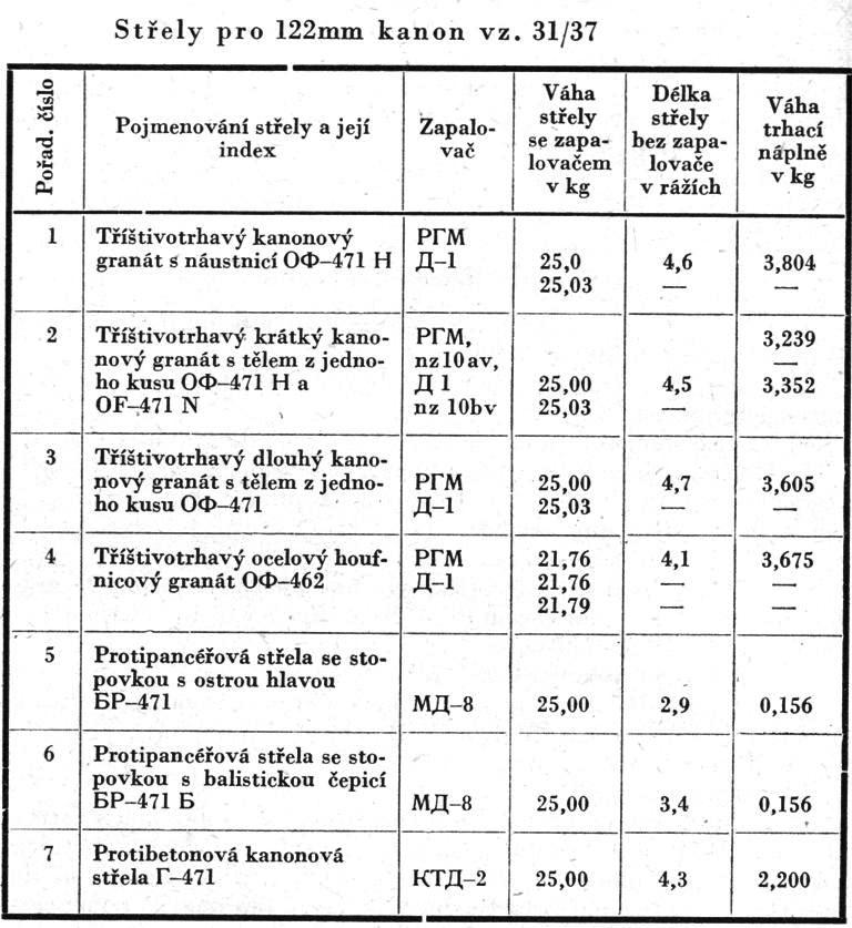


As a 122mm HE-Frag shell, the explosive payload was uniquely large and the projectile itself was particularly heavy. Even the older OF-471N shell with the smaller explosive payload exceeded the explosive payload of the 100mm OF-412 shell fired from the D-10T of the T-54 medium tank by more than two times, and the disparity grew even further when compared to the improved OF-471N model. OF-471N also had a more optimal ratio between the mass of the projectile casing and the explosive charge, so it possesses more favourable fragmentation characteristics. For comparison, the older OF-471N warhead casing weighs 21.46 kg and it contains a 3.35 kg TNT charge so the share of the explosive charge by mass is 15.6%, whereas the OF-412 projectile casing weighs 13.7 kg and contains a 1.46 kg TNT explosive charge, and the share of the explosive charge by mass is just 10.3%. The share of the explosive charge mass for the newer OF-471N was 18.1%. The smaller share of explosive mass in the OF-412 is a side effect of the thicker steel casing needed to withstand the heavy stresses of being launched at a muzzle velocity of 892 m/s. The OF-471N avoids this problem because it was originally an artillery round and it was designed to be launched at a more modest muzzle velocity of 795 m/s. However, OF-471N is significantly inferior to the OF-462 howitzer shell in terms of the filler weight ratio and the size of the lethal area, used in the M-30 and D-30 howitzers.
An even wider gap is found when foreign medium tank guns are compared, as a 20 pdr. HE shell fired from a British Centurion weighs just 7.8 kg and contains an explosive charge of only 0.6 to 0.75 kg of TNT (Mk. I) or Composition B (Mk. I/I), while a 90mm HE shell fired from the M3 guns of the M47 and M48 Pattons weighs 10.56 kg and contains an explosive charge of 0.925 kg. In other words, the OF-471N shell has 5.6 times more explosive content than the 20 pdr. HE shell and 3.62 times more explosive filler than a 90mm HE shell.
The OF-471N shell can have the RGM, RGM-2 (1978), or D-1 point-detonating fuzes fitted, but for a postwar tank, the D-1 fuze would usually be used. The D-1 fuze weighs 0.188 kg. The OF-471NZh uses the more modern V-429 fuze instead.
Muzzle Velocity: 795 m/s
Projectile Mass: 25 kg
Warhead casing mass: 21.46 kg or 21.0 kg
Explosive Charge Mass: 3.352 kg or 3.804 kg
To use the shell in the "Frag" mode, the fuze is left in the superquick setting and the fuze cap is removed. The shell detonates instantly upon impacting any surface, regardless of whether it is a body of water, a marsh, or snow, thus producing the maximum fragmentation effect on targets standing on top of the surface. If nothing is done prior to firing the shell, meaning that the fuze is left in the superquick setting and the fuze cap is left on, the shell behaves as a "HE-Frag" shell. The fuze detonates after a delay of 0.027 seconds and produces a combined high-explosive and fragmentation effect. If the fuze cap is left on but the fuze is set to the delayed setting, the shell is behaves as a "HE" shell. It is detonated after a much longer delay of 0.063 seconds after impact. This enables the shell to explode after penetrating the earth down to an optimal depth, thus displacing the largest possible volume of soil and delivering the maximum shock effect to enemy fortifications which tend to be below ground level by nature. For example, a trench can be destroyed by firing a HE shell at a point just in front of the trench. The shell penetrates the earth at an oblique angle and explodes just next to the wall of the trench (a lucky shot may even explode inside the trench itself), thus demolishing it and killing anyone in the way. Setting the fuze is done by the loader using a special key, but it is the commander who dictates which setting is most suitable for the target.
Being a HE-Frag shell with a point-detonating fuze, OF-471N is most effective against troops in the open, sheltered troops, soft-skinned vehicles, and field fortifications. The lack of an armour-piercing tip and a base fuze means that it is unsuitable for destroying reinforced concrete bunkers. Even when set to behave as a HE shell, the explosion is only capable of creating a large and deep dent in the wall of the bunker without significantly penetrating it. Repeated shots at the same area of the wall will eventually bust the bunker, so it is not impossible, but specialized anti-concrete shells are much more efficient for this purpose. Nevertheless, the effect of a HE shell on hard targets should not be underestimated.
Even against heavily armoured targets that the OF-471N could never hope to perforate, the blast of the shell could still cause serious injuries to the crew. A Soviet study found that when firing 122mm AP and HE shells at armoured vehicles with an armour thickness of 240mm, the impact generated shock waves inside the vehicle with a pressure of 0.57-1.52 kg/sq.cm as recorded by sensors placed 200-1,000mm from the surface of the armour plate. The back surface of the plate was not breached or compromised in any way in any of the tests in the study as that would invalidate the results. It was noted in a separate report that a pressure of 0.4-0.6 kg/sq.cm is enough to cause medium injuries to humans, including the temporary loss of consciousness, hearing damage, bleeding from the nose and ears, and fractures or twisting of the limbs. A pressure wave of 0.57-1.52 kg/sq.cm can produce heavy hearing damage and blast injuries to the body, leading to an inability to continue fighting.
These effects are probably not as intense as that of a HESH shell of comparable caliber detonating against a plate of comparable thickness, but still, the effectiveness of 122mm HE-Frag shells on heavily armoured tanks was proven in combat during WWII.
When set to the Frag mode, the shell merely detonates on the surface of an armour plate and does not inflict much damage except in certain circumstances, but when set to the HE mode for penetration, OF-471N can tank armour and form extremely large breaches, killing the crew and destroying internal equipment with a large mass of fragments. Thinner plates can be perforated without causing too much damage to the point-detonating fuze that it is unable to function, so the shell may explode behind the plate. But if a sufficiently thick plate is fired at, the shell might perforate without detonating since the point-detonating fuze would be destroyed.
Soft-skinned targets such as trucks, tractors and cars (Jeeps, Land Rovers) can be destroyed without requiring a direct hit if the shell has the fuze set to the superquick mode. In such cases, the fragmentation deals most of the damage. Armoured personnel carriers, light tanks, armoured cars and other lightly armoured vehicles can also be knocked out by a near miss, although some of the heavier vehicles may require a direct hit or even a direct hit with the shell set in the delayed penetration mode. It is worth noting that even HE-Frag shells in the 76mm caliber were already enough to handle light tanks, not to mention less well-armoured vehicles.
Soviet testing detailed in "Report on the shooting of German tanks with AP and HE shells from tank guns" from 1942 also indicated that 76.2mm HE-Frag shells fired from an F-34 tank gun proved to be capable of destroying early medium tanks like the Pz.38(t) and Pz.III from distances of up to a kilometer in a side attack. If set to the "Frag" mode mode, the detonation of a 76.2mm shell on the surface of the hull sides of these tanks could not blow through the side armour plate but they would destroy the suspension. Adding on to that, 76mm HE shells from obr. 1931 guns (a high velocity anti-air gun) were reportedly capable of perforating 45 mm of armour at 30 degrees from 500 meters and 50 mm of armour at 30 degrees can be perforated from 300 meters or closer. With that in mind, it is also unsurprising that 85mm HE shells fired from the ZiS-S-53 gun of the T-34-85 were reported to be capable of knocking out Pz.III tanks from 800 meters.
It is obvious that 122mm HE-Frag shells can achieve these results and more, but the higher rate of fire obtained from smaller caliber tank guns makes them more efficient on a shot-per-shot basis. On the other hand, a valid counterargument is that a 122mm HE-Frag shell fired in the superquick mode is powerful enough to destroy the suspensions of light vehicles with fragmentation and blast alone while also dealing with dismounted infantry, making it somewhat more efficient, especially at longer ranges where a direct hit is simply not guaranteed. Using the shells in HE mode and aiming for direct hits may not be as viable.
OF-471N may be capable of defeating the side armour of several contemporary medium and heavy tanks, but the most interesting targets are the Centurion and Conqueror as these tanks had spaced side skirts. For reference, it is interesting to recall that German testing of "Schurzen" spaced armour panels in 1943 found that the spaced panels could detonate 76mm HE-Frag shells fired from ZiS-3 guns. The panels were badly damaged, but they served their purpose by shielding the suspension from the blast and splinters.
Armour-Piercing
53-VBR-471B
53-BR-471B

The BR-471B shell was one of two armour-piercing shells originally available to the T-10 in 1953. The BR-471 shell of WWII vintage can skipped over even though wartime stockpiles of this obsolete shell still existed because T-10 tanks were simply not intended to use this shell, given that the TSh2-27 and TPS1 sights were only marked for BR-471B rounds.
Although the BR-471 shell was the standard armour-piercing round for IS-2 tanks during WWII, the BR-471B shell already began supplanting it in 1945, albeit too late to see combat in Europe, and it replaced the BR-471 entirely during the 1950's. The main targets of BR-471 shells during its heyday were German tanks such as Panthers and Tigers, against which it was generally quite successful. Even Tiger II tanks could fall victim to this shell under certain circumstances. However, its performance on sloped armour plate, and its long range energy retention, were both not ideal as it was a simple sharp-tipped projectile.
The BR-471B shell was superior on both counts as it had a blunt tip underneath a ballistic cap, and the projectile had a more elongated and streamlined shape, giving it a better ballistic coefficient. The BR-471 shell had a worse ballistic coefficient as it did not have a ballistic cap on top of its pointed penetrator body, and it two annular grooves around the midsection of its body that acted as local structural weakened zones where the tip of the shell could break off when impacting highly oblique armour. By allowing the penetrator to fail at predetermined points, the catastrophic failure of the entire penetrator could be avoided. The shell could then continue its interaction with the armour plate as a blunt-tipped shell rather than an ogive-tipped shell. The sensitivity of ricocheting from thinner but highly oblique plates was also reduced.

BR-471B already had a blunt tip so that when it impacts an oblique plate, an edge of its tip will dig into the plate and the resistance of the armour generates a righting torque, countering the effect of the deflecting force. This can improve performance on sloped armour plate and also increases the plate thickness and obliquity threshold for a ricochet. Moreover, rather than perforating armour through ductile hole formation, blunt-tipped shells tend to defeat armour through plug formation. This requires less energy and, if the target armour has a low toughness, allows the BR-471B penetrator to defeat a greater thickness of armour despite having the same mass and velocity as BR-471. The gap in the penetration power widens at longer distances as BR-471B loses less speed thanks to its superior ballistic coefficient.

The body of the BR-471B projectile is made from KhZNM steel. The shape of the body is cylindrical from the driving band to the localizer grooves. Ahead of the frontmost localizer groove, the body is ogived for a length of 1.9 calibers, The base is boattailed.
In the later half of WWII when the 122mm D-25T became the new standard gun of Soviet heavy tanks, the BR-471 and BR-471B shells produced at the time had a hardness of up to 481 BHN. This was considerably lower than the steel armour-piercing shells of German and American production which maintained a hardness of 550-600 BHN, but it was already an improvement over earlier Soviet shells from the earlier half of the war which had a hardness ranging from 351-451 BHN. The quality of the metallurgy of postwar shells was substantially higher than shells produced during wartime as the Soviet munitions industry had managed to improve their hardening technology and methodology during the immediate postwar period, allowing the manufacturers to harden the steel penetrator body more rationally and to increase its overall hardness. BR-471 and BR-471B shells produced in the immediate postwar period were of considerably higher quality with a hardness of up to 590 BHN at the surface near the nose, but this still fell short of the U.S Army standard hardness of 60 HRC (654 BHN) at the nose. Moreoever, 100mm shells captured from SU-100 tank destroyers during the Suez Crisis of 1956 revealed that the hardening of BR-412B shells reached 622 BHN at the tip. This implies that BR-471B shells produced in the late 1940's and early 1950's also had the same standard of quality.
The explosive charge at the base of the shell was initiated by the MD-8 base fuze in early BR-471B shells. Later BR-471B shells have a DBR base fuze instead, later replaced by the DBR-2.
Muzzle Velocity: 795 m/s
Projectile Mass: 25 kg
Explosive charge: A-IX-2
Explosive Charge Mass: 0.156 kg
The point blank range of BR-471B is high enough that theoretically, a hit can be guaranteed on a typical medium tank at a range of over a kilometer. The point blank range is 970 m for a target with a height of 2.0 meters (representing an armoured personnel carrier), 1,120 m for a 2.7-meter target (medium tank), and 1,180 meters for a 3.0-meter target (heavy tank). Of course, the natural vertical dispersion of the shot makes it necessary to estimate the range with some precision to have any real chance of scoring a hit at such ranges, and the vertical dispersion increases if the tank is on the move or even if it has just recently stopped since the barrel will oscillate from movement.
Depending on the source, the penetration of BR-471B shells can vary by a considerable margin. One Soviet source gives the following figures:

U.S Army testing of captured BR-471B shells obtained from knocked-out IS-3 tanks gave the following results:

Although BR-471B may have been effective against late WWII-era tanks, postwar tanks such as the M47 Patton were much more challenging. The M47 was designed as the replacement of the M46 Patton, but it held this title for only a short period before it was supplanted less than a year after entering service by the new M48 Patton medium tank. Still, the M47 was not uncommon among U.S Army tank units until the early 1960's and it formed a massive part of the tank fleets of several NATO members in continental Europe as part of U.S military aid, and as such, it was a militarily significant tank model that the T-10 series was likely to encounter. The cast upper glacis armour of the M47 had a thickness of 100mm at a slope of 60 degrees.
The M48 had a more resilient upper glacis with a thickness of 110mm sloped at 60 degrees and an eliptical hull shape providing more efficient protection from armour-piercing projectiles. An impact velocity of 870 m/s was needed to guarantee the defeat the upper glacis armour of the M48 from the front and an impact velocity of 900 m/s is required from an ±18 degree side angle. The limit velocity for satisfactory penetrations of the upper glacis was 820 m/s from the front. The low muzzle velocity of 795 m/s of the BR-471B shell effectively renders it impotent against the upper glacis of the M48 even at point blank range, so a hit to the turret or the lower glacis is necessary.
The British Centurion tank had somewhat poorer chances of surviving an encounter with a T-10. Its upper glacis armour was merely 75mm thick and sloped at 57 degrees, and its turret was more vulnerable as it had a worse ballistic shape but its armour was not thick enough to compensate.
With this level of performance, BR-471B was sufficiently powerful against medium tanks of the immediate postwar era but it was already falling into obsolescence in the face of the newer M48 Patton. The addition of appliqué armour on Centurion tanks also made them a much more challenging foe.
HEAT
3VBK-6, 3VBK-6M
3BK-10, 3BK-10M

Given that 3BK-10(M) is functionally identical to the 3BK-9(M) round, this segment will only focus on its ballistic performance, which was entirely unremarkable for a projectile of its type. Its muzzle velocity was marginally higher than AP or HE-Frag rounds, but due to the increased drag from the stabilizer fins, higher drag of the spike tip projectile design and the smaller momentum of the lighter projectile, 3BK-10 loses velocity at a more rapid rate compared to spin-stabilized projectiles.
Like the 3BK-9 round, A-IX-1 is used for the explosive filler, and the V-15PG point-initiating base-detonating (PIBD) fuze is used.
The point blank range for a target with a height of 2 meters is just 900 meters.
3BK-10 (3BK-10M)
Muzzle Velocity: 820 m/s
Cartridge Mass: 26.13 kg
Projectile Mass: 18.0 kg
Explosive Charge Mass: 1.334 kg
Penetration at 0 degrees: 400mm RHA (450mm RHA)
Penetration at 60 degrees: 200mm RHA (220mm RHA)
(Official figures)
Penetration: 523mm RHA (593mm RHA)
(From Soviet study)
APDS
3VBM4
3BM7
Like the 3VBK-6 HEAT rounds, the 3BM7 rounds had an identical design to their more powerful counterparts for the M62 gun and entered service in the same year. The only functional difference was that the 3BM7 projectile had a lower muzzle velocity of 1,400 m/s as a result of the lower chamber pressure of the D-25TA and D-25TS guns. However, even though 3BM7 did not reach the same level of performance as 3BM11, it was already enough to ensure the defeat of all existing NATO medium and main battle tanks of the 1960's from the front at combat distances of 1,500 to 2,000 meters. The point blank range for a target with a height of 2 meters is given as 1,600 meters.
Projectile Mass: 7.4 kg
Core Mass: 2.82 kg
Muzzle Energy: 7,252 kJ
Penetration at 1 km:
300mm at 0 degrees
100mm at 60 degrees
Penetration at 2 km:
270mm at 0 degrees
90mm at 60 degrees
M62-T2

The M62-T2 is a rifled high-pressure tank gun with a horizontally-sliding breech block. It is chambered for the newly developed 122x759mm caliber and it would turn out to be the only gun chambered for this cartridge that ever entered service. Like the D-25TA, a loading assistance device with a powered chain rammer is installed adjacent the breech of the cannon. The mass of the loading assistance device acts as a counterbalance to the gun mask. However, the design of the M62-T2 was completely different from the D-25 series and it had nothing in common except the diameter of the bore, as even the loading assistance device on the M62-T2 was designed to operate with 122x759mm cartridges only. The M62-T2 gun weighs 2,785 kg, inclusive of the muzzle brake and fume extractor. This is comparable to the American M58 which weighs 2,848 kg. Together with the armoured gun mask, the total weight of the gun assembly is 3,397 kg.

The ammunition for the M62-T2 is proprietary. It is not possible to fire a shell in the 122x785mm caliber, mainly because the propellant charge would not fit into the chamber designed for a 759mm case. The ballistics of the M62 gun were unified with the D-74 field gun, but despite this, the cartridges were not officially shared. According to a T-10M manual, the cases for the ammunition are only marked for the M62-T2, without mention of the D-74 (index 122-D74).
One of the factors behind the increased muzzle energy of the M62-T2 compared to the D-25T series is the lengthened barrel. The barrel of the M62-T2 has a length of 6,393mm or 52.4 calibers instead of the 43-caliber barrel of the D-25T series. This was still substantially shorter than the American 120mm M58 which had a barrel length of 7,162mm or 60 calibers. The maximum operating pressure of an 122mm AP shell fired from the M62-T2 is 392 MPa. This is noticeably higher than the 330 MPa nominal chamber pressure and 372 MPa maximum pressure of the M58 gun.
The gun elevation limit for the M62-T2 is 15 degrees and the gun depression limit is -5 degrees. Compared to the D-25TA and D-25TS, the total range of elevation angles is the same but 2 degrees were taken from the positive elevation and essentially reallocated towards increasing the gun depression limit. This is partly due to the revised location and positioning of the recoil mechanism on the M62-T2 breech assembly.
The hydraulic recoil buffer is located on the bottom left corner of the breech and the hydropneumatic recoil recuperator is placed next to it in the bottom right corner of the breech. Due to the relocation of the recoil mechanism from above the gun breech to below it, the M62-T2 appears narrower than the D-25T, although its breech assembly had the same width of 480mm. This can be seen in the photo below by Yuri Maltsev.

The M62-T2 is well-balanced and will maintain equilibrium when all of the standard equipment is installed, including the loading assistance device. As usual, there are a stack of steel ballast plates placed behind the breech to act as removable counterweights. As the barrel bore is progressively worn down with repeated firings over time, the weight of the eroded bore material will shift the center of gravity to the rear, so the ballast plate should be incrementally removed to maintain equilibrium.
Although a maintaining perfect equilibrium seems to be a relatively trivial quality for a tank gun, it is actually not so simple. For example, the M58 gun on the M89 combination mount in the M103 heavy tank required a large hydraulic equilibrator mechanism with a hydraulic cylinder pressurized to 1,000 psi. This mechanism took up a very large amount of space above the breech assembly and increased the total weight of the gun assembly, not to mention that the failure of the equilibrator seal would leave the gun inoperable by power or manual means due to the immense weight of the gun, making it necessary to apply an overwhelmingly large amount of torque to control the gun should the equilibrator fail. It also made the turret taller than it could have otherwise been.

The safety mechanism of the M62-T2 prevents the firing of a loaded round by any method, mechanical or electrical, until the loader's safety switch is closed. This included the electric trigger system and the mechanical firing pin, both the solenoid-actuated and manually-cocked modes of firing using the trigger on the manual elevation handwheel and using the mechanical trigger lever respectively.
Despite the considerable increase in power compared to the D-25TA gun, the M62-T2 gun assembly is slightly more compact as its breech assembly has the same width but the recoil guard is shorter. This freed up space behind the recoil guard, most notably increasing the size of the gap between the back of the recoil guard and the turret ring, thus allowing additional racks for 122mm projectiles to be placed on the turret ring.

Besides that, the mask mount on the end of the gun cradle was modified to accept the new gun mask of the T-10M, and like on the D-25 guns installed in previous T-10 models, a light sheet metal fairing was attached to the end of the gun mask, but again, the reason for this item is unclear.


Protection from the muzzle blast of the coaxial machine gun may have been a somewhat plausible explanation for the previous tanks, but on the M62-T2, the sheet metal fairing does not even reach the muzzle of the KPVT and the KPVT has a conical flash hider instead of a muzzle brake anyway. The increased length of the fairing compared to the one on the D-25 guns of previous T-10 tanks could indicate that it is intended to be a sleeve for protection against fragmentation, but the low thickness of the fairing means that it would only stop fragmentation that is already too anemic to cause anything other than superficial damage to the gun barrel anyway.
At some point, a canvas gun mask shroud was added to seal the many small gaps around the gun embrasure. The canvas shroud was mainly useful during daily operation as it completely prevented rain water from entering the turret or dust from collecting in the gaps between moving parts. The photo on the left below is taken from "T-10 Heavy Tank and Variants" by James Kinnear and Stephen Sewell.


As before, the cannon is installed on a mounting cradle which in turn is installed in the turret with two trunnions. These two trunnion are secured to the turret with two trunnion pins which pass through the entire thickness of the frontal turret casting on either side of the cannon and can be seen externally when the cannon is elevated if a canvas gun mask shroud is not present, as shown in the photo on the left below. The photo on the right below shows the mount for the coaxial KPVT with the right trunnion pin visible underneath the mount (photo credit to Stefan Kotsch).


The normal length of the recoil stroke is 490 to 520mm and the maximum is 560mm. This is the same as the D-25T despite the greatly increased power of the gun. This was partly achieved thanks to a more sophisticated recoil mechanism, but the main design feature that permitted this was the new combined slotted-baffle muzzle brake.
The muzzle brake had six pairs of slots and it was affixed to the muzzle of the barrel with four bolts as shown in the photo below (credit to Vasily Chobitok.). It is used exclusively on the M62-T2 and is a surefire indicator to distinguish the T-10M from all previous models. The 100mm D-54TS high-velocity cannon had a derivative of this muzzle brake design with four pairs of slots instead of six.


A slotted-baffle muzzle brake, referred to as an active-reactive muzzle brake, works to counteract recoil force by a combination of the rearward thrust (reactive) from the redirected escaping propellant gasses escaping through the slots and the forward force exerted by the pressure of the escaping propellant gas acting on the baffles (active). The smaller size of the slotted baffles compared to the large baffles of the TsKAB muzzle brake reduces the available surface area that the propellant gasses can act upon, but the relatively large slots reduces the velocity of the escaping propellant gasses which consequently reduce the rearward thrust compared to a purely slotted muzzle brake.

The efficiency and recoil-damping effectiveness of such muzzle brakes is heavily dependent on the specific design in question, but A. Mashkin states in "Тяжёлый танк Т-10" that the slotted muzzle brake of the M62 gun has a very high efficiency of 70%. The downside to having such an efficient muzzle brake is that the recoil system would likely fail if the gun was fired without it or if the brake was defective in some way. Furthermore, the large volume of propellant gasses ejected to the sides with every shot increases the firing signature of the tank, but like the T-10A and T-10B with the periscopic TPS1 sight, obscuration of the gunner's vision would not be a major concern as the T-10M had the periscopic T2S-29-14 sight, so the high velocity of the propellant gas exiting the muzzle brake slots is helpful for clearing the gunner's view and helps the fumes dissipate more quickly.
122x759mm Caliber
Like all previous T-10 models, the standard combat loadout for the T-10M was evenly divided between HE-Frag ammunition and armour-piercing ammunition. Fifteen HE-Frag rounds and fifteen APCBC rounds would be carried. When HEAT ammunition became available in 1964, the share of APCBC rounds was reduced to only six, with the other nine having been replaced by HEAT rounds.
It is worth noting that the shape and ballistic properties of the spin-stabilized 122mm ammunition for the M62 was not the same as the 122mm ammunition for the D-25T, even though they shared the same caliber. The difference in the shape of the projectiles can be seen most clearly when the OF-472 is compared to the OF-471N. The radius of the ogive was increased, the bearing surface length was shortened, and the overall length of the projectile grew slightly. These changes were necessary to counteract the increased drag experienced by the projectiles as they traveled at a considerably higher velocity.

In the early 1960's, there was a desire to improve the firepower of the T-10M and the most expedient approach was to put an APDS round into service. The muzzle velocity was specified to be around 1,800-1,900 m/s and the armour penetration was calculated to be a whopping 200mm at 60 degrees at a distance of 2,000 meters. However, the chamber pressure of this APDS round reached 451.1 MPa, exceeding the maximum safe chamber pressure of 392 MPa by 15%. When the APDS round was fired during a live fire test in January 1963, the M62-T2 gun mounted on a tracked test platform experienced a catastrophic failure: a piece of the breech was blown off and the breech block itself followed, the gun cradle collapsed, the recoil guard and loading assistance device was demolished and the recoil mechanism was disabled. Needless to say, this APDS round was too powerful for M62-T2 to handle. An APDS round with reduced power had to be developed.
In 1967, the 3BM11 APDS round for the T-10M entered service. This addition was rather belated given that production of the heavy tank had already ceased completely by 1965, but even so, the availability of another new and more potent ammunition type extended the usefulness of T-10M tanks and made it a viable tool during the remainder of their service life until they could be replaced by new and more effective tanks equipped with powerful smoothbore guns. With the new APDS round, the number of HEAT rounds was reduced and obsolete APCBC rounds were omitted entirely. Beginning in the late 1960's, the combat loadout of each T-10M consisted of 18 HE-Frag shells, 8 APDS shells and 4 HEAT shells.
PROPELLANT CHARGES
The propellant charges for the M62-T2 cannon had a bottlenecked tapered case instead of a straight cylindrical case. The cases had a slightly reduced length compared to the straight-walled cases for the D-25T - only 759mm compared to 785mm - but had an increased diameter of 157mm and a rim diameter of 171mm. This made them slightly easier to handle in the confines of the tank, especially with the revised ammunition stowage layout of the T-10M. However, the charges also weighed more due to the increased mass of propellant. It can be assumed that the ergonomic benefits of the reduced length of the propellant charges were largely offset by the increased weight.
As mentioned before in the article, new semi-combustible propellant charges entered service for the T-10M in 1959. Moreoever, the new HEAT and APDS ammunition appearing in 1964 and 1967 were exclusively supplied with semi-combustible propellant charges.
As mentioned before in the article, new semi-combustible propellant charges entered service for the T-10M in 1959. Moreoever, the new HEAT and APDS ammunition appearing in 1964 and 1967 were exclusively supplied with semi-combustible propellant charges.
HE-Frag
3VOF-2 cartridges with the OF-472 HE-Frag shell use the 4ZhN4 propellant charge with a brass casing and NDT-2 19/1 propellant. The complete propellant charge weighs 20.25 kg and the brass casing alone weighs 9.75 kg. There is a waxed cardboard liner and obturator to seal the mouth of the casing and to phlegmatize the propellant for barrel cooling purposes, helping to reduce erosion.
3VOF-16 cartridges with the OF-472 HE-Frag shell use the 4Zh14 semi-combustible propellant charge. Weighing only 14.6 kg, the difference in weight between the 4ZhN4 brass-cased propellant charge and the new 4Zh14 semi-combustible propellant charge amounts to 5.65 kg. A waxed liner was absent as the semi-combustible casing material itself served as the phlegmatizer.

APCBC
3VBR-1 cartridges with the BR-472 APCBC shell use the 4ZhN3 propellant charge. The charge uses a brass casing with NDT-2 16/1 propellant. There is a waxed cardboard liner and a combustible cork with the shape of a truncated cone is affixed to the mouth of the propellant charge casing. It is 95mm long. The purpose of the cork is to ensure that the projectile is seated in the chamber when the propellant charge is rammed into position, because the projectile would tend to lay short of the forcing cone due to the shorter length of the projectile base behind its driving band relative to the HE-Frag shell. The presence of the cork also serves as a way for the loader to quickly identify it from the 4ZhN4 propellant charge to ensure that the incorrect propellant charge is not incorrectly loaded during the heat of battle, as it is inadmissible to use propellant charges interchangeably. The full propellant charge weighs 20.42 kg.
3VBR-3 cartridges with the BR-472 shell use the 4Zh15 semi-combustible propellant charge. The charge weighs only 14.77 kg - a very substantial improvement over the 4ZhN3 that undoubtedly made the loader's job easier. The combustible cork that was present at the mouth of the 4ZhN3 casing was replaced with a hollow spacer of the same shape, made from the same cellulose textile as the rest of the combustible casing.

HEAT
3VBK-5 cartridges with the 3BK-10 HEAT shell use the Zh26 propellant charge. The length of the Zh26 propellant charge is particularly short due to the presence of the stabilizer fins at the rear part of the projectile, so it had to be short to ensure that the projectile is seated properly in the chamber. However, the mass of propellant was not compromised because no air gaps were left inside the charge casing unlike the 4Zh15 and 4Zh14 propellant charges. The charge was shortened to the extent that no bottlenecking remained, which makes it easy to visually differentiate it from the propellant charges of the other ammunition types.
APDS
3VBM4 cartridges with the 3BM11 APDS shell use the 4Zh46 propellant charge. The hollow nose of the combustible casing of the propellant charge is extended to ensure that the exceptionally short APDS projectile is seated properly and engages with the rifling of the barrel, thus fulfilling the same purpose as the combustible cork found on 4ZhN3 charges. The propellant charge weighs 15 kg.

Due to the short length of APDS projectiles, there was an attempt to create a unitary APDS cartridge. This unitary cartridge only slightly exceeded the length of a standard propellant charge for an armour-piercing round so it could be loaded using the loading assistance device. Otherwise, two-piece APDS cartridges had to be loaded manually because the APDS projectile assembly was simply too short to be loaded properly by the chain rammer of the loading assistance device. However, the unitary APDS cartridge remained experimental.

HE-Frag
3VOF-2, 3VOF-16
OF-472

The only available types of HE-Frag ammunition for the M62-T2 were the full-charge 3VOF-2 or 3VOF-16, both having the same OF-472 shell. The OF-472 shell was also used for the D-74 field gun. A reduced charge cartridge was available for the D-74, but for the T-10M, only full propellant charges were available.
Although the upgrade to the M62-T2 improved the performance of armour piercing rounds, the unfortunate side effect is that the increased operating pressure required HE-Frag projectiles to have thicker walls in order to withstand the increased rate of acceleration inside the barrel. According to the Russian artillery ammunition design textbook "Устройство и действие боеприпасов артиллерии", the wall thickness of OF-472 is 0.17 calibers, as compared to 0.14 calibers for the OF-471N. Because of this, the mass of a complete projectile increased by 2.3 kg compared to the OF-471N shell.
The steel body of the OF-472 projectile weighs 23.34 kg. With a total projectile mass of 27.3 kg and a muzzle velocity of 885 m/s, the muzzle energy of the OF-472 shell is a whopping 10.69 MJ, so it is much more energetic than the 8.08 MJ of the OF-471N shell fired from the D-25T. This is beneficial when firing upon armoured targets, including tanks. However, it paid for the increased kinetic energy with a heavy sacrifice in its explosive payload, having only 3 kg of TNT filler compared to 3.35 kg of TNT in the OF-471N. The share of the explosive charge by mass was sub-optimal - only 11.8%. This is still marginally better than the 100mm OF-412 shell, but it falls far below the 15.6% ratio of the OF-471N shell.
One upside of the OF-472 design is that the sectional density of the projectile increased compared to OF-471N due to the larger weight, which has a positive effect on the ballistic coefficient. With the increased muzzle velocity, the ballistic trajectory of the OF-472 projectile became noticeably flatter and the maximum indirect fire range increased to 16 km despite the reduction in the maximum gun elevation angle from the 17 degrees of the D-25T to the limit of 15 degrees on the M62-T2. This is useful when a higher hit probability on point targets is required, but the flat trajectory is counterproductive when engaging infantry in the open because the fragmentation pattern is negatively affected. It also makes the shell more sensitive to ground ricochets when fired at flat ground at short ranges, so the coaxial KPVT of the T-10M may be needed to take over the anti-infantry role in such circumstances. Also, the increased range of the OF-472 shell is not very useful for a heavy tank like the T-10M as it would be an immense waste of resources to deploy it as a field gun instead of using it in its intended role. Overall, there was little good in the reduction of the explosive payload, but it was unavoidable due to the higher acceleration forces the shell experienced when it was launched from the high-pressure M62-T2 gun.
Muzzle Velocity: 885 m/s
Projectile length (without fuze): 564 mm
Projectile length (fuzed): 622mm (5.1 calibers)
Projectile body mass: 23.34 kg
Total projectile mass: 27.3 kg
Explosive filler mass: 3 kg
Projectile body mass: 23.34 kg
Total projectile mass: 27.3 kg
Explosive filler mass: 3 kg
APCBC
3VBR-1, 3VBR-3
BR-472

When the T-10M entered service, the 3VBR-1 round with the BR-472 shell was only armour-piercing ammunition initially available for the tank. It was not the first capped armour-piercing shell in the 122mm caliber as the BR-471D already existed, but it was the first and last APCBC round in the 122x759mm caliber to be issued in service. Like the BR-471D shell, the nose of the BR-472 armour-piercing cap is blunt and the steel armour-piercing core has an ogived tip.
The shell body (19.61 kg) is composed of 60Kh2N2M steel, while the armour-piercing tip (3.5 kg) is made from 48Kh3 (sometimes referred to as 48Kh30) steel. Both are grades of tool steel. According to the Russian munitions design textbook "Устройство и действие боеприпасов артиллерии", compared to earlier shells, more sophisticated heat treatment was utilized, providing through hardening, high tempering, hardening and rehardening of the nose, tempering of the shell base, and low-temperature tempering of the entire body. This provided higher hardness and strength. The nose of the shell was treated to a hardness of 57-63 HRC, with the hardness being maximum on the surface of the nose (down to the midsection of the shell) and gradually decreasing into the center of the shell. The base is treated to a Brinell hardness indentation diameter of 3.34-3.6 mm (285-332 BHN). These hardness specifications essentially correspond to that of American shells and to the Pzgr. 39 rot specifications from the later half of the GPW.
The armour-piercing cap soldered onto the penetrator body serves to prevent both penetrator breakup and shatter, particularly when attacking sloped armour. The presence of a blunt AP cap made localizer grooves uncecessary. Its hardness does not exceed 477 BHN, and the hardness of the base of the cap is 269-321 BHN.
The design of the shell is effectively the same as BR-471D, namely in the thickness (0.41 calibers) and length (1.03 calibers) of the armour-piercing cap, and the length of the ballistic cap (1.2 calibers). BR-472 only differs in that its total length is very slightly longer (3.72 calibers), the walls of the explosive cavity are marginally thinner (0.29 calibers), but more importantly, a new set of driving and obturator bands was introduced. The image below shows BR-472 on the left and BR-471D on the right.

The use of a capped shell with a sharp-nosed penetrator to replace the homogeneous blunt-nosed type established in 1945 was a result of the close similarity in impact behaviour on mildly oblique armour and the higher penetrating performance of a sharp-nosed penetrator, particularly on thick and tough, but softer armour. Such armour resists blunt-nosed penetrators well due to a high toughness, allowing it to resist failure by plugging, but is suboptimal for sharp-nosed penetrators, against which an armour plate of higher hardness is usually more effective. Since the armour-piercing cap effectively distributes the shock load across the entire surface of the ogived penetrator tip during impact, the penetrator remains intact throughout the interaction and maintains its tip, with the exception of high-obliquity impacts. Shell shattering or fracturing was also avoided, allowing the shell to exhibit better penetration performance than a homogeneous shell under the same conditions, except on high-obliquity impacts.
In terms of muzzle energy, the BR-472 shell was close to the 12.8cm Pzgr. 39 shell fired from a KwK 44 or a Pak 44 as that fired a 28.3 kg projectile at 950 m/s. Compared to the M358 round fired from the M58 gun of the M103 series, BR-372 is less energetic, though the difference is not as large as the commonly printed values suggest due to the use of a 21°C standard propellant temperature in the U.S, as opposed to a 15°C standard temperature as used in Germany and the USSR.
A 0.34 kg charge of A-IX-2 is packed at the base of the projectile. A DBR base fuze is screwed into the back of the explosive charge cavity and incorporates a tracer at the end. The tracer does not protrude beyond the rim of the projectile base which has some fairly interesting aerodynamic connotations.
The increased muzzle velocity of the BR-472 shell extended the point blank range to 1,130 meters for a target with a height of 2 meters. This is the average height of an APC hull. The combined height of the hull and turret of NATO tanks like the Centurion and M48 was 2.3 meters tall on average, but the M48 had a very large cupola that increased the height to 2.7 meters. Naturally, this made them much easier to hit.
Muzzle Velocity: 950 m/s
Projectile Length: 488mm
Projectile Mass: 25.1 kg
Muzzle Energy: 11,326.4 kJ
Penetration at 0 degrees:
500 m - 265mm
1,000 m - 247mm
1,500 m - 230mm
2,000 m - 214mm
Penetration at 30 degrees:
500 m - 214mm
1,000 m - 200mm
1,500 m - 186mm
2,000 m - 172mm
With this shell, the M48 Patton medium tank was vulnerable on its upper glacis from 1,000 meters and the frontal armour in general (including the turret) was vulnerable to a frontal shot from a distance of 1,500 meters or more. The more lightly armoured M47 would be even less likely to survive a direct hit from BR-472 at such distances. These tanks formed the bulk of the armoured forces of several NATO armies, the main one being the U.S Army, but just a few years after the T-10M was introduced, the M60A1 main battle tank made its appearance. The strong emphasis on armour obliquity on its turret and hull made it practically impervious to BR-472 except at the normal weakened zones - the lower glacis of the hull, the base of the turret cheeks, and the are below the gun mask.
The large gun mask of the M103 turret has a thickness of 254mm at the apex of its nose, thinning down to 102mm while gaining a slope of 45 degrees. The penetration figures for BR-472 indicate that this armour can be perforated from a distance of up to 1,500 meters.
3VBK-5, 3VBK-5M
3BK-9, 3BK-9M

The relatively high muzzle velocity of the projectile helps to improve the probability of scoring a hit on a distant target, especially a moving target. However, the use of a spike tip and stabilizer fins causes the projectile to experience greater air resistance during flight, so the rate of velocity loss is higher than the spin-stabilized BR-472 projectile and the difference between the velocities of the two shells will increase over distance.
The point blank range of 3BK-9(M) for a target with a height of 2.0 meters is 1,000 meters. This is a small improvement over the 3BK-10(M) round, but it is less than the point blank range of 1,120 meters for BR-472 for a target of the same height. The flatter trajectory of the 3BK-9(M) shell compared to the 3BK-10(M) shell despite having the same caliber and the same projectile design is due to its marginally larger mass and its higher muzzle velocity, courtesy of the higher pressure and longer barrel of the M62-T2 gun.
According to a 1979 Soviet report titled "Выбор Кумулятивных Снарядов Для Испытания Брони" (Selection of Cumulative Shells for the Evaluation of Armour), the average penetration of 3BK-9 in armour plate is 523mm with a maximum of 563mm and a minimum of 481mm. All of the penetration figures represent the performance at both 0 and 60 degrees. For comparison, the average penetration of the American 105mm M456A1 in the same targets was found to be 398mm, and the maximum and minimum penetration was 434mm and 355mm respectively. The Soviet 115mm BK-4M shell had an average penetration of 499mm with a maximum of 559mm and a minimum of 418mm.
The penetration power of 3BK-9M is not known for sure, but based on the performance ratio between the 115mm 3BK-4 (440mm RHA) and 3BK-4M (499mm RHA) and assuming a similar ratio exists between 3BK-9 and 3BK-9M, it can be deduced that the penetration of 3BK-9M is around 593mm and the maximum achievable penetration is around 638mm.
With such an impressive penetration power, 3BK-9(M) is capable of easily perforated the armour of any tank in the world with a large surplus of energy left to inflict heavy post-perforation damage. Case in point, 3BK-9M could perforate the thickest part of the upper glacis of an M103 twice over and 3BK-9 could do the same to the upper glacis of the Conqueror, so the probability of a mission kill on the first hit should be rather high. This creates a strong incentive for T-10M commanders to choose HEAT when dealing with heavily armoured targets over the BR-472 APCBC, especially since there is a relatively small difference in the ballistics between the two shells and none of the penetration power of HEAT is sacrificed at long range.
The V-15PG point-initiating base-detonating (PIBD) fuze is used.
3BK-9 (3BK-9M)
Muzzle Velocity: 920 m/s
Cartridge Mass: 31 kg
Projectile Mass: 19.2 kg
Explosive Charge Mass: 1.7 kg
Penetration (Official): 450mm RHA
Penetration: 523mm RHA (593mm RHA)
APDS
3BM11
3BM11 was developed during the late 1950's in a programme to increase the firepower of the 100mm D-10 and the M62 cannons. It entered service in 1967. The design of the projectile is almost identical to the 100mm 3BM8 projectile and the tungsten carbide core has the same dimensions. The only structural difference is in the size of the steel jacket and the sabot. The core is made from a tungsten carbide with a 10% nickel binder, designated as VN-10.

Unfortunately for the T-10M, the appearance of 3BM11 in 1967 was rather belated as the T-62 had already achieved its level of performance on sloped targets several years ago thanks to the virtues of APFSDS ammunition. The APFSDS rounds fired from the U-5TS gun of the T-62 were still inferior in penetration on flat targets, but this was largely irrelevant as armour with complex ballistic shapes and liberally sloped surfaces was the norm for all post-WWII tanks. Interestingly enough, the APFSDS rounds that were in development for the U-5TS were also tested in the M62-T2 cannon at the NIIBT testing grounds at Kubinka, but ultimately, only the smoothbore U-5TS was supplied with the new ammunition.
The 3BM11 round uses a reel-shaped cup-type sabot that is fundamentally the same as the sabot of the 3BM8 round in its working principle, but has a completely different construction due to the two-part ammunition of the M62-T2 gun. The sabot is joined to the subcaliber projectile by four pins and the base of the projectile is supported by the sabot. When the round is fired, the four pins are responsible for transmitting the rotational force imparted by the rifling to the subcaliber projectile.
As the entire projectile assembly leaves the muzzle of the barrel, both the sabot and the subcaliber projectile are rotating at the same rate but the sabot experiences much more aerodynamic resistance due to the large cavity at its front end. The sabot decelerates because of this, but the heavier subcaliber projectile carries much more momentum and it is much more streamlined. As a result, the four pins connecting the sabot to the projectile experience a strong shear force and are sheared off almost immediately after the projectile assembly stops accelerating from being propelled in the gun barrel, thus separating the subcaliber projectile from the sabot.


The four pins connecting the sabot to the projectile do not shear off when the round is fired because the base support offered by the cup spares the pins from the tremendous rate of acceleration, so they are left intact to transmit rotational energy.
This sabot design is simple in its operation. Compared to the complex sabots of foreign APDS rounds, the 3BM11 cup sabot has only a single separation stage whereas the sabots of rounds like the 105mm L28 and 120mm L15 first have three nose petals separate from centrifugal force before the cup separates from the subcaliber projectile due to air resistance.
With a muzzle velocity of 1,620 m/s and a higher sectional density than full caliber projectiles owing to its small caliber and the high density of its tungsten carbide core, 3BM11 has an exceptionally flat ballistic trajectory compared to BR-472, even more so than the 3BM7 round for the D-25T. Therefore, the probability of hit would be much higher on distant targets and especially if they are moving. The point blank range for a target with a height of 2.0 meters is given as 1,900 meters. Considering that tanks like the M48 Patton, M60A1 and Leopard 1 have a structural height of 2.3 meters (hull and turret only, ignoring ground clearance and cupolas), the actual point blank range on a typical NATO tank exceeds two kilometers. For comparison, the 100mm 3BM8 round has point blank ranges of 1,680 meters and 1,800 meters for a 2.0-meter target and a 2.3-meter target respectively.
Muzzle Velocity: 1,620 m/s
Total projectile assembly length (incl. sabot): 250mm
Total cartridge mass: 22.7 kg
Projectile Mass: 7.4 kg
Core Mass: 2.82 kg
Muzzle Energy: 9,710.3 kJ
Penetration at 2 km:
320mm at 0 degrees
190mm at 45 degrees
110mm at 60 degrees
From "Theory and Design of a Tank", P.P. Isakov, 1982
Penetration at 1 km:
370mm at 0 degrees
140mm at 60 degrees
Penetration at 2 km:
300mm at 0 degrees
115mm at 60 degrees
The penetration performance of 3BM11 is ostensibly inferior to L1G APDS from the Conqueror's L1 cannon on flat plates by a large margin, but it is apparently somewhat more effective on plates sloped at 60 degrees. This can be seen in the table below from the British Army Operational Research Group memorandum "Tank Effectiveness, Conqueror, Conway and Charioteer" from June 1954 as shared on the Tanks and AFV News website. According to DEFE 15/1183, the penetration of the "Conqueror APDS" is 125mm at 60 degrees at 1,000 yards.
As mentioned many times before on Tankograd, it is usually not possible to directly compare the penetration figures given by different sources due to differences in the penetration criteria and test methodology, and this is particularly true when comparing Soviet penetration figures with the figures from any other nation. However, the advantage held by the L1G round is quite far beyond the realms of possibility given that it is a 10.43 kg projectile travelling at a muzzle velocity of 1,280 m/s. The core of L1G is much more substantial than the core of 3BM11 at a weight of 5.44 kg, but due to the large difference in the muzzle velocities, the 3BM11 projectile carries 9.71 MJ of kinetic energy whereas the L1G projectile carries 8.54 MJ of kinetic energy.

Firing tables for 3BM11 are not publicly available and the only available firing table for 3BM8 is incomplete, but according to V.A Grigoryan in "Защита танков" (Tank Protection), 3BM8 has a muzzle velocity of 1,415 m/s and a velocity of 1,202 m/s at 2 km. The average rate of velocity loss from this small set of data comes out to 106.5 m/s per kilometer. It is doubtful that this figure is entirely true because the larger caliber L15A5 APDS projectile fired from the 120mm L11 gun is known to decelerate at a rate of 61 m/s per kilometer, but unfortunately, this is the only known source of information on this topic for the 3BM8. In the absence of better information, there is no choice but to assume that the ballistic characteristics of 3BM11 are similar enough to 3BM8 that these figures apply.
All of the figures are calculated for an impact velocity of 1,500 m/s. For 3BM11, this corresponds to a distance of 1 km. From the graph, it is shown that the penetration of 3BM11 into RHA at this distance is 400mm at 0 degrees, 370mm at 30 degrees, 310mm at 45 degrees, 150mm at 60 degrees, 100mm at 70 degrees, and 40mm at 80 degrees.
The graph on the left shows the actual penetration of the munitions across the range of target plate angles, and the graph on the right shows the penetration of the munitions in terms of actual line-of-sight thickness. Based on this data, it can be seen that the performance of 3BM11 actually increases gradually as the target obliquity increases from 0 degrees to around 41 degrees, after which a rapid drop is observed. The decay in penetration performance plateaus as the impact angle reaches 70 degrees, but it plummets again until 82 degrees is reached where it is presumably guaranteed to ricochet.

3BM11 was evaluated against spaced armour with various plate and air gap thickness configurations. The flash photographs below show the result of 3BM11 defeating a two-layer spaced armour pack set at 30 degrees with an 80mm RHA front plate, a 60mm air gap and a 20mm RHA back plate. The velocity limit of defeat was 1,230 m/s.

It can be seen that the addition of an 80mm air gap between a 100mm RHA front plate and a 200mm RHA back plate increases the relative effectiveness of the armour by 40% and effectively renders the target proof against 3BM11 except at point blank range as an impact velocity of 1,622 m/s is required to defeat it.

The test result from the shelling of the first two-layer spaced armour configuration listed in the table (20-300-200) is shown in the photo below. The photo on the top shows the crater in the 200mm RHA back plate after it successfully stopped the APDS round at an impact velocity of 1,393 m/s. The photo on the bottom shows the perforation channel of the APDS round in the 200mm RHA back plate at an impact velocity of 1,429 m/s. This test data confirms that the calculated velocity limit of 1,413 m/s for the spaced armour configuration is correct. The second spaced armour configuration with a larger air gap is not significantly more effective than the first, despite the increase in the air gap size by 217%. However, both are 40% more effective than a homogeneous 220mm RHA plate, showing that 3BM11 is sensitive to relatively light spaced armour screens.

But besides simply illustrating the effectiveness of 3BM11 on various spaced armour targets, the table also gives the velocity limits for homogeneous armour plates of the same armour weight. For example, the 20-300-200 spaced armour weighs the same amount as a solid 220mm RHA plate, and the table shows that a 220mm RHA plate can be defeated at an impact velocity of 1,000 m/s.
From the table, it can be seen that a 300mm RHA dual-layered block made by stacking a 100mm RHA plate on top of a 200mm RHA plate is actually marginally more effective at stopping 3BM11 compared to a solid homogeneous 300mm RHA block; while a solid 300mm block can be defeated at an impact velocity of 1,220 m/s, a dual-layered block can only be defeated at 1,235 m/s. It is known that stacked plates can have a noticeable effect on solid steel AP and APC shots, but in this case, a difference of only 15 m/s indicates that 3BM11 is only negligibly affected.

At an impact velocity of 1,246 m/s, the 3BM11 core narrowly failed to fully perforate the target and left a large cracked bulge on the rear surface of the 200mm plate. This directly contradicts the data given in the table since 1,246 m/s is in excess of the 1,235 m/s perforation limit, but this can be explained by the fact that the penetration path of the projectile deviated from the perpendicular axis while travelling through the second plate. This phenomenon can be attributed to a few factors such as the possible heterogeneity of the plate quality, quality variances in individual penetrator cores, the sturdiness of the testing rigs, and more.
At an impact velocity of 1,272 m/s, the 3BM11 core successfully defeats the target as expected, leaving a hole in the plate equivalent to the tungsten penetrator core in diameter. The penetration path is more or less completely straight. Based on the available information, the limit velocity of 1,235 m/s corresponds to a distance of 3.5 kilometers. This shows that the reported penetration of only 300mm or 320mm RHA at 2 km is nowhere near the actual limit of the performance of 3BM11.

COAXIAL, ANTI-AIRCRAFT MACHINE GUNS
DShKM

The T-10 was equipped with a DShKM heavy machine gun as its co-axial machine gun. The DShKM is an open-bolt single-feed heavy machine gun chambered in the 12.7x108mm cartridge. To fit the machine gun into the gun mask, the front and rear sight blocks were removed, although tanks in museums often seem to have DShKMs with the rear sight block intact. Its great length of 1,588mm and prominent muzzle brake meant that a considerable portion of its barrel had to protrude rather openly outside the gun mask, and due to the gas vent of its long-stroke gas mechanism, the machine gun had to be positioned so that it vents out through the gap between the gun mask and the turret, and the turret seal of the coaxial port is fitted behind the gas vent. It has a barrel length of 967mm and a total barrel length of 1,069 with the large muzzle brake included. The cyclic rate of fire is 600 rounds per minute. This is similar to contemporary machine guns like the M2HB and not inferior to most 7.62mm machine guns, but in practice, the practical rate of fire is expected to be lower than a small caliber machine gun for various reasons, the primary one being the more limited ammunition supply. When installed in the T-10, the large muzzle brake of the DShKM protrudes prominently outside the gun mask as shown in the photo below (from "T-10 Heavy Tank and Variants" by James Kinnear and Stephen Sewell).

A total of a thousand rounds of 12.7mm ammunition is carried in the tank. 50 rounds are provided in a single non-disintegrating steel belt held in a box, of which six are carried in ready racks. The anti-aircraft machine gun is supplied with a 150 in three boxes. The ammunition boxes for the two machine guns are not interchangeable since the coaxial DShKM feeds from the right whereas the anti-aircraft DShKM feeds from the left, and the types of rounds contained within them are not the same. An additional 550 of reserve ammunition is carried in zinc boxes. These zinc boxes are stowed at the rear of the hull. In order to use the reserve ammunition supply, the loader must collect expended belts or obtain empty belts from somewhere else, reload them with the loose cartridges from the zinc boxes, and lay them into empty ammunition boxes. The main drawback of the DShKM is the limited ammunition capacity compared to an SGMT which is fed from 250-round boxes. With only 50 rounds at the gunner's disposal, the machine gun is limited to a practical rate of fire of 80 rounds per minute. The 11 kg weight of the large 50-round boxes for the DShKM is also greater than the 9.4 kg weight of the 250-round boxes for the SGMT, making them somewhat more difficult to handle inside the confines of a tank.
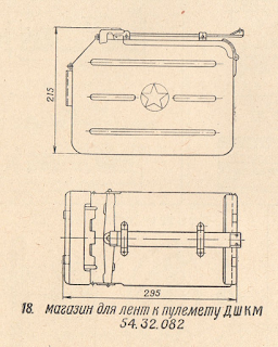


The barrel of the DShKM is removable, but it is not possible to do so while the weapon is locked in its coaxial mount. In fact, it is not possible to remove it from inside the tank without exiting. This is because the large muzzle brake is larger than the machine gun port, so removing the machine gun requires the prior removal of the muzzle brake from outside the tank.


The concept of installing a coaxial large caliber machine gun to supplement the main cannon was not new by the time the T-10 began development; the IS-4 had a DShKM as its coaxial weapon and the IS-7 was armed with the particularly powerful KPVT together with a rather excessive number of external 7.62mm machine guns. However, it was by no means a standard practice for Soviet heavy tanks as the IS-2 and IS-3 both had a 7.62mm DTM coaxial machine gun.

The DShKM retains the same basic functionality as a DTM or SGMT machine gun, but unlike a 7.62mm machine gun, it is suitable for engaging troops behind cover and thin-skinned vehicles at longer distances by virtue of its more powerful cartridge. However, a 12.7mm machine gun is less efficient against troops in the open as the practical rate of fire is lower due to the small ammunition capacity and limited ammunition supply. Even though a direct hit from a 12.7mm bullet of any type is instantly lethal, a direct hit from a 7.62mm bullet achieves practically the same effect and the volume of fire from a 7.62mm machine gun can be much higher, so the probability of scoring a direct hit tends to be higher as well. The DShK was also not originally designed to be used in enclosed combat vehicles, unlike the American M85. Its large width of 161mm was not a problem for external mounts but it took up a lot of space inside a tank, and its operating mechanism was not designed with confined spaces in mind. Nevertheless, it was a robust weapon and it was not troublesome in use.
Standard B-32 armour-piercing incendiary (AP-I) and BZT armour-piercing incendiary tracer (API-T) rounds were provided for the coaxial DShKM. B-32 and BZT bullets contain 1.03 grams (16 grains) of aluminium-magnesium-barium nitrate incendiary compound in the tip. The mass of the incendiary compound in both bullets is substantially greater than the 0.84 grams (13 grains) of magnesium-barium nitrate incendiary compound contained in the British .50 caliber L11A1 and L13A1 spotting bullets used in the British Centurion and Chieftain and is marginally greater than the 0.97 grams of aluminium-magnesium-barium nitrate incendiary compound (IM 11) contained in the American .50 caliber API-M8 bullet. Beginning in 1954, the B-32 obr. 1954 bullet was slightly lengthened to accommodate an additional incendiary charge behind the steel core to improve the damage inflicted on targets behind armour plates. Combined with the sparking from the impact of the steel core, B-32 rounds could generate an exceptionally good flash signature on hard targets, particularly metal ones.
Standard B-32 armour-piercing incendiary (AP-I) and BZT armour-piercing incendiary tracer (API-T) rounds were provided for the coaxial DShKM. B-32 and BZT bullets contain 1.03 grams (16 grains) of aluminium-magnesium-barium nitrate incendiary compound in the tip. The mass of the incendiary compound in both bullets is substantially greater than the 0.84 grams (13 grains) of magnesium-barium nitrate incendiary compound contained in the British .50 caliber L11A1 and L13A1 spotting bullets used in the British Centurion and Chieftain and is marginally greater than the 0.97 grams of aluminium-magnesium-barium nitrate incendiary compound (IM 11) contained in the American .50 caliber API-M8 bullet. Beginning in 1954, the B-32 obr. 1954 bullet was slightly lengthened to accommodate an additional incendiary charge behind the steel core to improve the damage inflicted on targets behind armour plates. Combined with the sparking from the impact of the steel core, B-32 rounds could generate an exceptionally good flash signature on hard targets, particularly metal ones.
For the coaxial DShKM, the AP-I and API-T rounds are fed in a 3:1 ratio, or in other words, there are three B-32 bullets for every BZT bullet in a standard belt. This is the standard configuration for coaxial machine guns and is similar to the 4:1 mix of M8 AP-I and M20 API-T carried by American tanks, and indeed, similar to any other machine gun. The BZT bullet has a tracer burnout range of 1,500 meters. It is worth noting that without tungsten-cored ammunition, the capabilities of the standard ammunition mix are relatively limited against armoured personnel carriers designed with frontal protection against 12.7mm machine guns. In "Современные Отечественные Патроны, Хроники Конструкторов", the fourth book of the four-part monograph "Боевые Патроны Стрелкового Оружия" by the ballistician V.N. Dvoryaninov, the calculated probability of knocking out an M113 with 7 hits of 12.7mm fire from the front was provided for three different belt compositions to evaluate the usefulness of including tungsten-cored 12.7mm AP-I bullets.
On a flat RHA target, the armour penetration capability of the 12.7mm B-32 bullet is directly equivalent to .50 caliber APM2 fired from an M2 Browning and is slightly superior to .50 caliber API-M8 and APIT-M20. The APM2 bullet travels at a muzzle velocity of 894 m/s and has a 25.9 gram steel core whereas the B-32 bullet travels at a muzzle velocity of 840 m/s and has a 30.0 gram steel core. The diameter of the steel cores of both bullets is 10.8mm, and as such, the B-32 bullet has a larger sectional density. Unsurprisingly, the larger sectional density and the larger elongation of the B-32 bullet granted it a higher ballistic coefficient, providing better energy retention at distance. Case in point - the impact energy of the APM2 bullet at 914 meters (1,000 yards) is 6,544 J, whereas B-32 has an impact energy of 7,000 J. This can also be observed in the maximum ranges of the B-32 compared to APM2 - the B-32 bullet fired from a DShK can travel up to 7,000 meters, whereas an M2 bullet fired from an M2HB can travel 6,583 meters (7,200 yards). The main advantage of APM2 is at shorter ranges, where its higher muzzle velocity grants a shorter time of flight and a flatter trajectory. For instance, the time of flight to 500 meters is 0.69 seconds for the B-32, but an M2 bullet takes 0.64 seconds to reach the same distance, and while the maximum ordinate of a B-32 bullet at 500 meters is 0.55 meters, the maximum ordinate of an M2 bullet at the same range is 0.5 meters.
- Belt option 1 - 3x B-32, 1x BZT-44 (standard belt mix)
- Belt option 2 - 1x B3S, 2x B-32, 1x BZT-44
- Belt option 3 - 3x B3S, 1x BZT-44
With these three options, the following probabilities of defeat were calculated.
| Distance (m) | Belt 1 | Belt 2 | Belt 3 |
|---|---|---|---|
| 100 | 0.57 | 0.68 | 0.83 |
| 200 | 0 | 0.31 | 0.67 |
| 300 | 0 | 0.12 | 0.33 |
| 400 | 0 | 0.10 | 0.27 |
As the table shows, a typical burst from a DShKM will be effective on an M113 from the front only at a distance of 100 meters or less. Beyond 100 meters, fire from the machine gun is ineffective without BS or B3S tungsten-cored ammunition, but even so, if the steel-cored AP-I is not fully exchanged for tungsten-cored AP-I on a one-to-one basis, the effectiveness will still be quite low at extended ranges. The coaxial DShKM can only be considered effective against armoured personnel carriers if the T-10 gunner has the opportunity to fire upon the flanks.
On a flat RHA target, the armour penetration capability of the 12.7mm B-32 bullet is directly equivalent to .50 caliber APM2 fired from an M2 Browning and is slightly superior to .50 caliber API-M8 and APIT-M20. The APM2 bullet travels at a muzzle velocity of 894 m/s and has a 25.9 gram steel core whereas the B-32 bullet travels at a muzzle velocity of 840 m/s and has a 30.0 gram steel core. The diameter of the steel cores of both bullets is 10.8mm, and as such, the B-32 bullet has a larger sectional density. Unsurprisingly, the larger sectional density and the larger elongation of the B-32 bullet granted it a higher ballistic coefficient, providing better energy retention at distance. Case in point - the impact energy of the APM2 bullet at 914 meters (1,000 yards) is 6,544 J, whereas B-32 has an impact energy of 7,000 J. This can also be observed in the maximum ranges of the B-32 compared to APM2 - the B-32 bullet fired from a DShK can travel up to 7,000 meters, whereas an M2 bullet fired from an M2HB can travel 6,583 meters (7,200 yards). The main advantage of APM2 is at shorter ranges, where its higher muzzle velocity grants a shorter time of flight and a flatter trajectory. For instance, the time of flight to 500 meters is 0.69 seconds for the B-32, but an M2 bullet takes 0.64 seconds to reach the same distance, and while the maximum ordinate of a B-32 bullet at 500 meters is 0.55 meters, the maximum ordinate of an M2 bullet at the same range is 0.5 meters.
Information on the penetration power of the 12.7mm B-32 and BZT bullets is available in a 1971 USAARMDL handbook titled "Survivability Design Guide For U.S Army Aircraft Volume II: Classified Data for Small-Arms Ballistic Protection".


From the table on the left, it can be seen that the penetration of the B-32 bullet at its muzzle velocity in RHA is 29.5mm (1.16") at 0 degrees, 21.8mm (0.86") at 30 degrees, 14.2mm (0.56") at 45 degrees, and 9.1mm (0.36") at 60 degrees. The penetration performance of the BZT bullets is much lower due to the presence of a tracer, as shown in the table on the right. Besides this, it is stated on page 6 of the March 1998 issue of the "Техника И Вооружение" magazine that the penetration of B-32 at a 0 degree angle is 20mm at 350 meters which aligns perfectly with the penetration table, but it is also stated that the BZT bullet achieves the same penetration at a slightly shorter distance of 300 meters which is plainly impossible.
For comparison, the .50 caliber M2 AP round penetrates 30.5mm of RHA steel at its muzzle velocity of 2,935 ft/s when fired from the 45-inch barrel of an M2HB machine gun under the Navy criterion (full bullet passage through armour plate). Its penetration drops to 19.1mm (0.73") at 30 degrees, 12.7mm (0.5") at 45 degrees, and only 6.35mm (0.25") at 60 degrees. As such, the penetration power of the M2 AP bullet is comparable to the B-32 bullet at 0 degrees, but falls short as the target obliquity increases.

However, Russian testing of the two bullets on 20mm plates of 2P high hardness steel (MIL-DTL-46100 grade) set at 0 degrees revealed that the M2 bullet has a slight advantage, being able to perforate it at a distance of 450 meters whereas the B-32 bullet manages to do so at 400 meters. Against the same 20mm plate of 2P steel but angled at 20 degrees, the M2 requires a range of 100 meters, but B-32 requires the range to be at point blank (muzzle velocity) to achieve perforation. The V80 standard was used for these tests, requiring that 80% of the bullets could achieve a full perforation instead of only 50% under the V50 standard used by foreign nations. This can be attributed to the fact that the core of the B-32 is made of high hardness carbon steel, rather than the high hardness alloy steel of the APM2 bullet. On softer metal plates less capable of breaking up impacting bullets, B-32 has the advantage.
At 100 meters, the penetration of the B-32 bullet is 26.9mm (1.06") in RHA. However, the 12.7mm B-32 bullet is credited with only 20mm of penetration at 100 meters according to Russian literature. This is because of a difference in the standards used to evaluate penetration performance. This Russian figure is a guaranteed minimum where 90% of all bullets will perforate a 20mm RHA plate at the specified distance and 75% of perforations will ignite 70 octane petrol (Soviet grade B-70) placed behind the plate. The U.S Army uses a V50 rating system where only 50% of hits are required to fully perforate the target. This is typically done with six shots where three complete perforations (a 0.5mm aluminium sheet placed six inches behind the target plate must be pierced) and three partial perforations (bulge or crack at the rear of the target plate) are achieved.
But besides its armour penetration power and incendiary effects, it is also worth noting that 12.7mm B-32 should be able to defeat a typical single-layer sandbag fortification from around 200 meters which is not possible for a 7.62mm bullet to achieve from any distance. As an example, it is noted in manuals for the M2 machine gun series such as the training document TC 3-22.50 (shown below) that protection from a single shot of .50 cal AP or API-T at 200 meters requires 3 layers of 8 to 10-inch sandbags. Rocks, logs, berms and other forms of natural cover that would otherwise be largely impervious to a burst of 7.62mm bullets are also more readily defeated by 12.7mm rounds. Rapid demolition of brick and concrete structures barring thick reinforced concrete bunkers also became possible thanks to the increased caliber of the coaxial machine gun. Rather than simply suppressing concentrations of entrenched enemy infantry with little hope of scoring a direct hit, a large caliber machine gun combines a powerful psychological effect with a much more tangible destructive effect.

However, the primary practical incentive to mount a large caliber machine gun as a coaxial weapon instead of a typical 7.62mm machine gun was to conserve the limited supply of 122mm ammunition available in the tank by providing a useful alternative against light fortifications, structures and lightly armoured vehicles. Given the opportunity, the DShKM would likely have been used to great effect against many lightly armoured vehicles including prime movers, utility vehicles as well as several early Cold War armoured personnel carriers like the M59 and Alvis Saracen, not to mention a wide variety of other vehicles that would probably have been pressed into service in the 1950's if another European conflict flared up. Notable examples include the M3 half-track and Universal Carrier, both of which were very numerous and rather lightly armoured. However, later types such as the American M113 armoured personnel carrier would be a somewhat more challenging target as the 12.7mm caliber had insufficient power to reliably defeat the frontal armour of the M113 and FV432 from beyond 200 meters. According to various Soviet and Russian sources, the maximum effective range of the DShKM on lightly armoured vehicles is claimed to be 500 meters.
The merits of a heavy machine gun as a coaxial weapon were explored outside of the Soviet Union by practically every major military. The U.S Army made an effort to arm their medium and heavy tanks with a .50 caliber M2HB machine gun alongside the standard M1919 but when the M47 and M103 (both with dual coaxial machine gun mounts) entered service, the M1919 was installed exclusively in practice. The French Army went ahead and armed their AMX-30 main battle tank with a .50 M2HB caliber coaxial machine gun before eventually upgrading it to a 20mm autocannon on the AMX-30B in 1972. Early prototypes of the British Centurion Mk. 1 medium tank were armed with a Polsten 20mm autocannon in an independently elevated mount, but this was scrapped fairly quickly in favour of a 7.92mm BESA machine gun. These mixed results came about due to the lack of an incentive for these tanks to have anything larger than a .30 caliber machine gun for a coaxial weapon since they generally had a plentiful supply of main gun rounds which they could afford to expend on lightly armoured vehicles and a .30 caliber machine gun was enough for practically everything else.


From the table on the left, it can be seen that the penetration of the B-32 bullet at its muzzle velocity in RHA is 29.5mm (1.16") at 0 degrees, 21.8mm (0.86") at 30 degrees, 14.2mm (0.56") at 45 degrees, and 9.1mm (0.36") at 60 degrees. The penetration performance of the BZT bullets is much lower due to the presence of a tracer, as shown in the table on the right. Besides this, it is stated on page 6 of the March 1998 issue of the "Техника И Вооружение" magazine that the penetration of B-32 at a 0 degree angle is 20mm at 350 meters which aligns perfectly with the penetration table, but it is also stated that the BZT bullet achieves the same penetration at a slightly shorter distance of 300 meters which is plainly impossible.
For comparison, the .50 caliber M2 AP round penetrates 30.5mm of RHA steel at its muzzle velocity of 2,935 ft/s when fired from the 45-inch barrel of an M2HB machine gun under the Navy criterion (full bullet passage through armour plate). Its penetration drops to 19.1mm (0.73") at 30 degrees, 12.7mm (0.5") at 45 degrees, and only 6.35mm (0.25") at 60 degrees. As such, the penetration power of the M2 AP bullet is comparable to the B-32 bullet at 0 degrees, but falls short as the target obliquity increases.

At 100 meters, the penetration of the B-32 bullet is 26.9mm (1.06") in RHA. However, the 12.7mm B-32 bullet is credited with only 20mm of penetration at 100 meters according to Russian literature. This is because of a difference in the standards used to evaluate penetration performance. This Russian figure is a guaranteed minimum where 90% of all bullets will perforate a 20mm RHA plate at the specified distance and 75% of perforations will ignite 70 octane petrol (Soviet grade B-70) placed behind the plate. The U.S Army uses a V50 rating system where only 50% of hits are required to fully perforate the target. This is typically done with six shots where three complete perforations (a 0.5mm aluminium sheet placed six inches behind the target plate must be pierced) and three partial perforations (bulge or crack at the rear of the target plate) are achieved.
But besides its armour penetration power and incendiary effects, it is also worth noting that 12.7mm B-32 should be able to defeat a typical single-layer sandbag fortification from around 200 meters which is not possible for a 7.62mm bullet to achieve from any distance. As an example, it is noted in manuals for the M2 machine gun series such as the training document TC 3-22.50 (shown below) that protection from a single shot of .50 cal AP or API-T at 200 meters requires 3 layers of 8 to 10-inch sandbags. Rocks, logs, berms and other forms of natural cover that would otherwise be largely impervious to a burst of 7.62mm bullets are also more readily defeated by 12.7mm rounds. Rapid demolition of brick and concrete structures barring thick reinforced concrete bunkers also became possible thanks to the increased caliber of the coaxial machine gun. Rather than simply suppressing concentrations of entrenched enemy infantry with little hope of scoring a direct hit, a large caliber machine gun combines a powerful psychological effect with a much more tangible destructive effect.

However, the primary practical incentive to mount a large caliber machine gun as a coaxial weapon instead of a typical 7.62mm machine gun was to conserve the limited supply of 122mm ammunition available in the tank by providing a useful alternative against light fortifications, structures and lightly armoured vehicles. Given the opportunity, the DShKM would likely have been used to great effect against many lightly armoured vehicles including prime movers, utility vehicles as well as several early Cold War armoured personnel carriers like the M59 and Alvis Saracen, not to mention a wide variety of other vehicles that would probably have been pressed into service in the 1950's if another European conflict flared up. Notable examples include the M3 half-track and Universal Carrier, both of which were very numerous and rather lightly armoured. However, later types such as the American M113 armoured personnel carrier would be a somewhat more challenging target as the 12.7mm caliber had insufficient power to reliably defeat the frontal armour of the M113 and FV432 from beyond 200 meters. According to various Soviet and Russian sources, the maximum effective range of the DShKM on lightly armoured vehicles is claimed to be 500 meters.
The merits of a heavy machine gun as a coaxial weapon were explored outside of the Soviet Union by practically every major military. The U.S Army made an effort to arm their medium and heavy tanks with a .50 caliber M2HB machine gun alongside the standard M1919 but when the M47 and M103 (both with dual coaxial machine gun mounts) entered service, the M1919 was installed exclusively in practice. The French Army went ahead and armed their AMX-30 main battle tank with a .50 M2HB caliber coaxial machine gun before eventually upgrading it to a 20mm autocannon on the AMX-30B in 1972. Early prototypes of the British Centurion Mk. 1 medium tank were armed with a Polsten 20mm autocannon in an independently elevated mount, but this was scrapped fairly quickly in favour of a 7.92mm BESA machine gun. These mixed results came about due to the lack of an incentive for these tanks to have anything larger than a .30 caliber machine gun for a coaxial weapon since they generally had a plentiful supply of main gun rounds which they could afford to expend on lightly armoured vehicles and a .30 caliber machine gun was enough for practically everything else.
ANTI-AIRCRAFT DShKM

For anti-aircraft work, there is a pintle-mounted DShKM machine gun on a gun cradle attached to the rotating loader's cupola. This is the same design as the loader's cupola of the T-54 obr. 1951 and the anti-aircraft machine gun mount and cradle are interchangeable. As mentioned before in this article in the section on the T-10 loader's station, the pintle attached to the loader's cupola is fixed in place. The machine gun mount is installed in the pintle by simply putting its base pin into the pintle slot and then tightening the pintle clamp. The machine gun can be elevated by 85 degrees and depressed by -5 degrees, making it a useful tool against both ground targets and air targets. Besides the infrared spotlight on the commander's cupola, there are no obstructions on the turret roof to prevent the machine gun from being fully depressed, so the loader is largely guaranteed a free field of fire in azimuth.

The machine gun mount can be swiveled in a full 360-degree arc about its axis on the pintle, and it can be locked facing any direction. If the machine gun is locked facing backward, it will not overhang the turret so it is less likely to snag onto any obstacles, but it will block the opening of the hatch. Locking it in the forward position allows the loader to aim and fire the machine gun from a natural position out of his hatch. The photo below from "T-10 Heavy Tank and Variants" by James Kinnear and Stephen Sewell shows the loader's cupola with its pintle.

To aim the machine gun in azimuth, the loader must rotate his entire cupola with his own bodily strength, and to aim it in elevation, the elevation hand wheel is worked to move the machine gun along a toothed arc. There is also a braking mechanism on the elevation hand wheel that acts as an elevation lock for the machine gun. It is actuated by a lever on the handle of the wheel that releases the brake when pressed to allow the machine gun to be elevated and depressed, so once the loader has aimed at a fixed target, he should release the lever to lock the machine gun in place before opening fire for maximum accuracy.
The loader fires the machine gun by depressing the trigger lever on the fixed handle on the left of the gun mount which pulls on a Bowden cable connected to the trigger on the back of the DShKM receiver. Since the DShKM still retains its spade grips and its original finger trigger when mounted in this configuration, it can be fired manually if needed and it can be used if it is dismounted from the machine gun cradle.
Due to the cantilever installation of the DShKM, the gun cradle has a pair of large equilibrator springs to ensure that the machine gun can be elevated with a uniform effort throughout its entire 90-degree range. Photo on the left by Yuri Maltsev from the Armor Journal website.


The cyclic rate of fire of 600 rounds per minute made the DShKM an adequate weapon for anti-aircraft purposes, but it was inferior to the American M85 in this regard as the M85 had an adjustable rate of fire and it could be set to fire at 800-950 rounds per minute; up to 50% faster than the DShKM. The limited supply of 50 rounds per ammunition box may have been a detriment to the practical rate of fire of the machine gun as there would be too few rounds to put out sustained fire against low-flying aircraft. It may not be an issue when firing at any aircraft making a pass at a short distance as the operator can afford to empty the entire box in one long burst and he will manage to reload before the aircraft comes for another pass. Since the aircraft only appears intermittently, the maximum volume of fire can delivered against it whenever it is needed. It is another matter when firing at ground targets because the time spent reloading generally has a much more direct impact on the volume of fire delivered to the enemy.
Aiming at ground targets is accomplished with either the standard iron sights on the DShKM or the K-10T anti-aircraft collimator sight. The K-10T facilitates accurate aiming at both ground level and high altitude targets, although the basic leaf sights on the machine gun itself would be more appropriate for aiming at ground targets as it can be adjusted for various distances. According to the manual, the K-10T should be zeroed for a distance of 400 meters. Fire correction would only be possible by observing the fall of the tracers and using the elevation scales in the reticle as a reference. The sight has a tinted screen in front of the collimator display to reduce glare. If it is not needed, it can be flipped down and out of the way. When flipped up, the screen darkens the background enough that there is a high enough contrast for the projected reticle to appear clearly in the operator's vision, allowing him to engage air targets with both eyes open.

The reticle of the K-10T is illuminated via a light collecting lens, which receives environmental light from a front-facing lens and magnifies it to project an illuminated image onto the reflector, with which the operator aims. In low-light conditions, the operator must fit a special battery-powered lamp onto a purpose-built bracket in front of the light collector lens to provide an artificial source of light for the illuminated reticle.
For anti-aircraft purposes, the collimator sight has an ideal design and location to provide the operator with a maximum field of view while allowing him to aim regardless of how he is positioned, which changes depending on the elevation angle of the machine gun, as the operator does not need to adjust his head to obtain a correct eye relief as with iron sights. The proper method of aiming with the sight is for the operator to keep both eyes open and look through the sight with his his right eye, allowing his brain to perceive the projected sight reticle in his vision through both eyes. Moreover, as long as the right eye is used to aim and there is 165-250mm of eye relief, the operator's field of view is not obstructed by the stowage box next to the sight.
The anti-aircraft DShKM uses a different belt with AP-I, API-T and HEI-T rounds in a 1:3:1 ratio.
KPVT

The KPVT is an open-bolt single-feed heavy machine gun, replacing the DShKT as the coaxial machine gun in the T-10M. It fires the 14.5x114mm cartridge at a cyclic rate of 550-600 rounds per minute. It has a barrel length of 1,348mm, but the total length of the barrel including the conical flash hider and booster assembly is 1,496mm. When configured as the coaxial machine gun, the KPVT from the right and ejects spent casings downward. It can be fired using the control handles on the T2S-29-14 sight or using the firing button on the manual gun elevation handwheel.

The machine gun cycles by short recoil operation. The reciprocating barrel is shrouded by a rigid air-cooling jacket. Propellant gasses entering the booster assembly at the muzzle push the barrel against the end of the jacket, causing the barrel and barrel assembly to recoil backwards a short distance after every shot which unlocks the bolt and propels it rearward to cycle the feed system. The reciprocation of the barrel assembly also marginally reduces the recoil impulse of the machine gun and makes it more manageable on vehicle mounts, thus fulfilling a similar function as the large muzzle brake on the DShK series to a lesser degree without incurring the drawbacks, such as a large muzzle flash - which the DShK is quite famous for - and a loud firing signature. Additionally, the conical flash suppressor at the muzzle of the gun further reduces the muzzle flash, making it an equally subtle weapon as the DShK despite firing a much more powerful round. For the curious, this video shows the field disassembly of a KPVT and this video gives an in-depth examination of the machine gun (in Russian)
A pair of shock absorber springs are integrated in the gun cradle for the KPVT on the coaxial mount. Part of the recoil force is damped by these shock absorbers, leading to reduced vibrations and increased firing accuracy. This is not an unusual feature for a coaxial machine gun mount, but for the KPVT, it has particular relevance as tight dispersion is crucial to attaining a long effective range on point targets, which is one of the main justifications of the increased power of the KPVT compared to the DShKM.
One of the main features of the KPVT that differentiates it from the standard KPV infantry machine gun was its forward-ejection mechanism for spent cases, which was considered mandatory for machine guns adapted for tank usage.

The cases are ejected downward and pushed forward by a special lever. In a T-10M, the machine gun mount includes a special guide chute under the gun barrel that leads to an ejection port outside the tank, closed by a spring-loaded lid. This chute can be clearly seen in the drawing below. By ejecting spent cases out of the tank, the amount of clutter inside the fighting compartment is significantly reduced and the air contamination from propellant fumes is kept under control.

The coaxial mount is at the same location next to the gun breech assembly. Owing to its increased size, the KPVT takes up even more space inside the turret of the T-10M in both width and length compared to the DShKM. Its greater length of 2,007mm was only partially offset by having a larger portion of the long barrel exposed outside the gun mantlet, but the receiver of the machine gun still protrudes deeper into the turret compared to the DShKM.
As the coaxial machine gun, the KPVT is loaded and cycled manually by the loader. Cocking the bolt is done with a large spring-loaded cocking lever. To ready the KPVT for loading, the loader pulls the handlebar backward to pull the bolt to the cocked position. The spring tension assists the loader in overcoming the resistance of the recoil spring and it also keeps the cocking lever in the rearmost position. Then, to load the machine gun, the top cover is opened and the belt is inserted into the feed tray like any other belt-fed machine gun. Once the top cover is closed, the machine gun is ready to fire and the bolt does not need to be recocked for any subsequent reloads as it locks itself in the cocked position after the last shot. The machine gun cradle and the cocking lever can be seen in the photos below (courtesy of Stefan Kotsch), although the spring for the cocking lever has been unhooked in the photo and the entire assembly appears worn and disheveled. Spent belt segments are collected in a metal bin placed directly underneath the machine gun. The collection bin is fixed, but there is a sliding trap door on the side to empty the bin when it is full. Again, this can be seen in the photos below.


The M62-T gun shown below lacks a bore evacuator and it is not fitted for stabilization like the M62-T2 gun, but it shares all of the other features found on the M62-T2. The spent link collector bin for the coaxial KPVT can be clearly seen hanging under the gun. This photo also makes it apparent that the coaxial KPVT machine gun is so long that it almost reaches the breech block opening on the side of the breech assembly. This was the reason why the loading assistance device control box had to be moved from its original position.

A total of 744 rounds of 14.5mm ammunition is carried in the tank. Of this amount, 200 rounds were provided for the coaxial machine gun and 250 rounds were provided for the anti-aircraft machine gun, all in 50-round boxes. All of the bullets and belts are interchangeable, but the boxes are not. Proprietary ammunition boxes with a distinct "lunch pail" shape were provided for the coaxial KPVT, which feeds from the right whereas the anti-aircraft KPVT feeds from the left and uses standard ammunition boxes. The peculiar ammunition boxes for the coaxial KPVT can be seen marked '21' and '25' in the drawing below. Also, the mix of bullet types for the coaxial and anti-aircraft machine guns are entirely different and may not be well-suited to different targets if exchanged. Another 294 rounds of ammunition are carried in sealed zinc tins as a reserve supply.

A ready supply of 200 rounds for the coaxial machine gun is not particularly large despite the high power of the 14.5mm caliber, but on the other hand, the ready supply for the anti-aircraft machine gun is quite plentiful relative to medium tanks like the T-54 series as those tanks carried a total of 300 rounds for their 12.7mm anti-aircraft machine guns. From another perspective, it could be argued that the total ready supply of 500 rounds for the T-10M is acceptable because is just one box shy of the full 500-round ammunition load for the KPVT of a BRDM-2 or a BTR-60PB, but these light vehicles also included a coaxial PKT machine gun with two thousands rounds of ammunition which invalidates the comparison. On the T-10M, it is quite likely for the entire supply of ammunition for the coaxial machine gun to be expended in a single engagement which would not have been a real problem for preceding tanks such as the IS-3, as that had a DTM for its coaxial machine gun with 756 rounds available at any time in 12 drums with another 1,244 rounds in sealed zinc tins in reserve stowage. On the other hand, the DTM was not an ideal tank machine gun either - experience had shown that it could not provide a sufficient volume of fire due to the relatively small capacity of its 63-round drums and the rapid overheating of the barrel.
Interestingly enough, issues with the ammunition capacity were recognized very early on. The Object 265 experimental prototype was developed from 1952 to 1953 and several samples were built in 1954 to explore alternative armament options for the T-10. It incorporated two coaxial machine guns: a KPVT and an SGMT - a bona fide belt-fed 7.62mm machine gun. A thousand rounds of ammunition would be carried for the SGMT in 250-round boxes, but the total quantity of 14.5mm ammunition dropped to just 510 rounds. The prototypes passed their state trials, but it was never disclosed if the dual coaxial setup was a more effective alternative to the single KPVT that was finally chosen for the T-10M.
Although the cyclic rate of fire of the KPVT is 550-600 rounds per minute, the practical rate of fire is officially listed as 70-80 rounds per minute in the manual. The practical rate is achieved by limiting fire to short bursts of 2-5 rounds. When necessary, long bursts of up to 20 rounds against ground targets may be used, and when engaging aerial targets, the machine gun is fired in long bursts exclusively. For a KPV used in its infantry mount and a KPVT used in a BTR turret, continuous full automatic fire is permitted up to 150 rounds, after which it is necessary to let the barrel cool. However, the barrel jacket of the KPVT mounted in a T-10M is almost entirely recessed inside the turret with most of its length enshrouded by armour. As such, there is almost no flowing air to cool the barrel and hardly any room for convection to occur. Because of this, it is likely that the heat limit of its barrel is less than 150 rounds in continuous fire.
In recognition of the issues with the DShKM mount in earlier T-10 models, the inability to remove the machine gun from inside the tank was corrected by implementing a coaxial machine gun port with a larger diameter on the T-10M mask casting. No special design solution was needed because the flash hider of the KPVT has the same diameter as the barrel jacket, making it a simple matter to extricate or install the machine gun in the mount from inside the tank. During snorkeling operations, the KPVT is removed from its mount and a protective watertight cover is closed over the port opening. The photo on the left below is by Vladimir Yakubov and the photo on the right below is by Stefan Kotsch. Both photos also show the spring-loaded lid for the spent case ejection port underneath the KPVT barrel.


The upgrade to the KPVT was largely influenced by the upgrade to the more powerful M-62T2 cannon which fired full caliber rounds at a higher muzzle velocity than the D-25T series. With a muzzle velocity of 1,000 m/s, the ballistic trajectory of the bullets fired from the KPVT were a close match for the OF-472 shells up to a distance of 1.2 km. As such, the upgrade from the DShKM to the KPVT was not simply for the sake of having more firepower, but was done with practical considerations for the fire control and armament of the tank as a holistic system.
The bullet types supplied for the coaxial KPVT included the 57-BZ-561S cartridge with the B-32 bullet containing a hardened steel core (AP-I), the 57-BZT-561 cartridge with the BZT bullet containing a downsized hardened steel core and a tracer (API-T), the 57-BZ-562 cartridge with the BS-41 bullet containing a tungsten-carbide (cermet) core (AP-I), and the 57-BZT-562 cartridge with the BST bullet containing a downsized tungsten carbide core and a tracer (API-T). Like the DShKM coaxial machine gun of previous T-10 models, the AP-I and API-T rounds are linked in the same 3:1 ratio in a standard belt for the KPVT. There are no specific instructions on how the bullet types are mixed, but the ballistics of the steel-cored bullets are distinct from the cermet-cored bullets and the tracer bullets only correspond to AP-I bullets of the same core material. As such, a standard mix will either consist of a ratio of three B-32 bullets and one BZT bullet or three BS-41 bullets and one BST bullet. In practice, the types of bullets encountered in combat will depend on availability. The four bullet types can be seen in this collection of sectioned cartridges. The drawings shown below, courtesy of Przemysław Konicki, show good cross-section drawings of the four main bullet types used in the KPVT together with a ZP (I-T) bullet which is only used in the anti-aircraft gun.


The B-32 bullet contained 1.3 grams of aluminium-magnesium-barium nitrate incendiary compound in the tip and the BZT bullet contained 1.56 grams of the same incendiary compound, which is substantially more than the 0.84 grams of magnesium-barium incendiary compound in .50 caliber spotting rounds. The tracer of the BZT bullet burns out at 2,000 meters. These characteristics made the KPVT an excellent ranging machine gun as the flash of the impact would be more visible at long distances and in poor weather conditions.
The BS-41 bullet also contained 1.3 grams of aluminium-magnesium-barium nitrate incendiary compound in the tip. The BST bullet had an incendiary charge of the same mass in the tip, but had a tracer with a burnout distance of only 1,500 meters. This was due to the greater mass of the cermet core compared to the steel core of the BZT bullet. If used for ranging purposes, the maximum measuring distance would be somewhat shorter than with the BZT bullet paired with the B-32.
The bullet types supplied for the coaxial KPVT included the 57-BZ-561S cartridge with the B-32 bullet containing a hardened steel core (AP-I), the 57-BZT-561 cartridge with the BZT bullet containing a downsized hardened steel core and a tracer (API-T), the 57-BZ-562 cartridge with the BS-41 bullet containing a tungsten-carbide (cermet) core (AP-I), and the 57-BZT-562 cartridge with the BST bullet containing a downsized tungsten carbide core and a tracer (API-T). Like the DShKM coaxial machine gun of previous T-10 models, the AP-I and API-T rounds are linked in the same 3:1 ratio in a standard belt for the KPVT. There are no specific instructions on how the bullet types are mixed, but the ballistics of the steel-cored bullets are distinct from the cermet-cored bullets and the tracer bullets only correspond to AP-I bullets of the same core material. As such, a standard mix will either consist of a ratio of three B-32 bullets and one BZT bullet or three BS-41 bullets and one BST bullet. In practice, the types of bullets encountered in combat will depend on availability. The four bullet types can be seen in this collection of sectioned cartridges. The drawings shown below, courtesy of Przemysław Konicki, show good cross-section drawings of the four main bullet types used in the KPVT together with a ZP (I-T) bullet which is only used in the anti-aircraft gun.
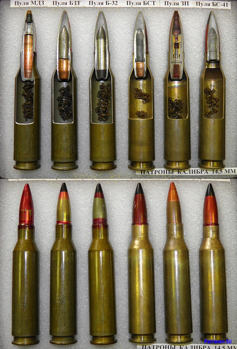


The B-32 bullet contained 1.3 grams of aluminium-magnesium-barium nitrate incendiary compound in the tip and the BZT bullet contained 1.56 grams of the same incendiary compound, which is substantially more than the 0.84 grams of magnesium-barium incendiary compound in .50 caliber spotting rounds. The tracer of the BZT bullet burns out at 2,000 meters. These characteristics made the KPVT an excellent ranging machine gun as the flash of the impact would be more visible at long distances and in poor weather conditions.
The BS-41 bullet also contained 1.3 grams of aluminium-magnesium-barium nitrate incendiary compound in the tip. The BST bullet had an incendiary charge of the same mass in the tip, but had a tracer with a burnout distance of only 1,500 meters. This was due to the greater mass of the cermet core compared to the steel core of the BZT bullet. If used for ranging purposes, the maximum measuring distance would be somewhat shorter than with the BZT bullet paired with the B-32.
| Weapon | 300 m | 500 m | 700 m | 1000 m |
|---|---|---|---|---|
| NSV (12.7mm BS) | 20.4 | 26.6 | - | - |
| NSV (12.7mm B-32) | - | - | - | - |
| KPVT (14.5mm B-32) | 23 | 23 | - | - |
When firing upon an M113 from the side, the following number of rounds are needed from each weapon.
As the results show, a KPVT firing steel-cored AP-I rounds can be expected to knock out a typical armoured personnel carrier with the expenditure of around half an ammunition box during a 500-meter engagement. Beyond 500 meters, the degradation in hit probability slightly erodes the economical justifications of relying upon the KPVT to engage vehicles as a substitute to the main gun, even when it is capable of penetrating its armour, as up to two 50-round boxes may be needed when engaging targets at a kilometer or more. Overall, the best results are obtained from an NSV machine gun equipped with full belts of tungsten-cored BS rounds, but supplying such quantities of BS rounds is itself an unrealistic option. However, when comparing these two weapons on the basis of their capabilities using standard steel-cored AP-I rounds, the advantage of the KPVT is very stark. By mounting the KPVT as its coaxial weapon, the T-10M was granted the ability to confidently eliminate a wider variety of lightly armoured vehicles from longer distances than was previously possible with the DShKM. Once again, information on the penetration of B-32 bullets come from the 1971 USAARMDL handbook titled "Survivability Design Guide For U.S Army Aircraft Volume II: Classified Data for Small-Arms Ballistic Protection".
| Weapon | 300 m | 500 m | 700 m | 1000 m |
|---|---|---|---|---|
| NSV (12.7mm BS) | 19.6 | 24 | 32 | 59 |
| NSV (12.7mm B-32) | 27.3 | 33.5 | - | - |
| KPVT (14.5mm B-32) | 24.5 | 29.6 | 37.5 | 97.6 |
As the results show, a KPVT firing steel-cored AP-I rounds can be expected to knock out a typical armoured personnel carrier with the expenditure of around half an ammunition box during a 500-meter engagement. Beyond 500 meters, the degradation in hit probability slightly erodes the economical justifications of relying upon the KPVT to engage vehicles as a substitute to the main gun, even when it is capable of penetrating its armour, as up to two 50-round boxes may be needed when engaging targets at a kilometer or more. Overall, the best results are obtained from an NSV machine gun equipped with full belts of tungsten-cored BS rounds, but supplying such quantities of BS rounds is itself an unrealistic option. However, when comparing these two weapons on the basis of their capabilities using standard steel-cored AP-I rounds, the advantage of the KPVT is very stark. By mounting the KPVT as its coaxial weapon, the T-10M was granted the ability to confidently eliminate a wider variety of lightly armoured vehicles from longer distances than was previously possible with the DShKM. Once again, information on the penetration of B-32 bullets come from the 1971 USAARMDL handbook titled "Survivability Design Guide For U.S Army Aircraft Volume II: Classified Data for Small-Arms Ballistic Protection".


From the table, it can be seen that the penetration of the B-32 bullet in RHA is 32.8mm (1.29") at the muzzle, 30.0mm (1.18") at 100 meters, 26.9mm (1.06") at 300 meters, 23.9mm (0.94") at 500 meters, and 15mm (0.59") at 1,000 meters. Needless to say, a 14.5mm B-32 bullet is much more powerful than a 12.7mm B-32 bullet. Additional information given on page 6 of the March 1998 issue of the "Техника И Вооружение" magazine indicates that 14.5mm B-32 penetrates 20mm RHA at 0 degrees at 800 meters which fits perfectly into the American penetration data.
Information on the BS-41 tungsten-cored bullet is more scarce, but it is known that its nominal penetration at 0 degrees amounts to 40mm of RHA at 100 meters, 35mm RHA at 350 meters, 32mm RHA at 500 meters, and 20mm RHA at 1,000 meters. According to data provided by Dvoryaninov, BS-41 is guaranteed (≥90%) to perforate 30mm of medium hardness steel (RHA) set at 20 degrees at 350 meters, or 30mm of high hardness steel at 20 degrees at 140 meters. When firing at a flat 30mm RHA target from 100 meters, the probability of igniting a container of gasoline behind the plate is ≥80%. BS-41 is also capable of penetrating 125mm of 5083 aluminium armour (same grade as used on the M113 APC) at 100 meters.
By having the KPVT, it also became possible to reliably defeat single-layer sandbag fortifications and natural cover from longer distances than was previously possible with the DShKM. Indeed, the PTRD and PTRS anti-tank rifles chambered for the 14.5mm cartridge were often used to defeat light fortifications and machine gun nests during WWII when there were no armoured targets to shoot at. Lightly armoured vehicles like the M113 and FV432 were, of course, prime targets as their frontal armour would not be able to withstand a 14.5mm B-32 bullet even from more than half a kilometer away and their side armour could be defeated from more than a kilometer away, even with a non-perpendicular impact. Light tanks like the AMX-13, M41 Walker Bulldog and M551 Sheridan could also be vulnerable to an attack to their sides from between 500 to 1,000 meters away. If cermet-cored BS-41 bullets are used instead, the range at which the KPVT is effective against lightly armoured vehicles undoubtedly increases, but the lack of a detailed penetration table makes it more troublesome to find the exact limits of its capabilities. However, given that the tracer burnout distance of the BST bullet is 1,500 meters, it is at least known that the maximum effective firing range is somewhat shorter than with the steel-cored B-32 and BZT.
Officially, the effective range of the KPVT on lightly armoured vehicles is stated to be 1,000 meters and the maximum effective range on unarmoured targets or infantry is 2,000 meters. The burnout of the tracers and the dispersion of the bullets makes it ineffective to open fire further than 2,000 meters except on area targets, but the 122mm main gun is far more appropriate under such circumstances.
ANTI-AIRCRAFT KPVT


To fire the machine gun, the loader presses the electric thumb trigger on the elevation handwheel handle. When the trigger is depressed, it also engages the electric braking system to freeze the cupola in azimuth so that the firing accuracy against static targets is maximized. The brake can be disabled for firing at moving targets.

Like the DShKM, the cyclic rate of fire of 600 rounds per minute of the KPVT was reasonable for anti-aircraft purposes but it was not outstanding, and like the smaller machine gun it replaced, the practical rate of fire of the KPVT was also limited by the ammunition supply in the same ways. The probability of hit with the KPVT against aircraft should be higher thanks to the higher muzzle velocity of its bullets and superior sighting instruments, and the probability of inflicting debilitating damage to aircraft should definitely be higher thanks to the larger mass of each 14.5mm bullet compared to their 12.7mm counterparts.
When using the anti-aircraft machine gun in a combat situation, the loader is effectively limited to 100 rounds of ammunition. One box of 50 rounds is immediately available on the machine gun mount, and another box of 50 rounds is stowed on the right side of the turret for a rapid reload. Another three boxes of reserve ammunition are stowed inside the tank, but two of these are located on the turret floor underneath the main gun and the other is underneath the commander's seat, and as such, they are difficult to access and it is difficult for the loader to transfer the large boxes out of his hatch and onto the anti-aircraft mount or onto the external stowage mount. Practically speaking, this would have to be done in a non-combat situation only. The mount for the externally-stowed anti-aircraft ammunition box is shown in the photo below.

The mix of bullet types is different from the coaxial KPVT to reflect the poorly-armoured nature of the intended target: fixed-wing jet and propeller-powered aircraft. Non-tracer and tracer rounds are loaded in a 2:1 ratio, with the anti-aircraft belts containing 57-Z-564 cartridges with MDZ bullets containing an explosive-incendiary charge (HE-I) and 57-ZP-561M cartridges with ZP bullets containing an incendiary charge and a tracer (I-T). The two bullet types can be seen in this collection of sectioned cartridges.
MDZ bullets are miniaturized explosive bullets detonated by an impact fuze. MDZ bullets are ineffective at defeating armoured targets but are capable of igniting fuel in metal containers with wall thicknesses of 2mm to 8mm via its explosive-incendiary charge (A-IX-2). As such, MDZ bullets can easily perforate the thin skin of aircraft and set internal equipment alight. According to data provided by Dvoryaninov, the reliability of fuzing on a 2mm duralumin sheet at a firing range of 100-1,500 meters is ≥90%, and the nominal probability of igniting TS-1 grade kerosene in a container situated behind a 2mm sheet of duralumin at 100-1,500 meters is ≥80%. MDZ bullets may also be extremely effective against thin-skinned vehicles such as trucks, but a possible issue with the use of MDZ bullets on targets other than aircraft and thin-skinned vehicles is the potentially inconsistent reliability of the fuze on any surface that is softer than sheet metal, including concrete and wood. However, even if the fuze does not initiate, the bullets themselves are more than capable of defeating brick and concrete walls and other forms of light cover with enough residual energy to remain lethal. Interestingly enough, the T-10M manual states that MDZ bullets should only be used on aircraft even though it is clearly also effective against other targets. This unusual instruction may be related to certain legal prohibitions on the use of explosive bullets on humans.
ZP bullets are incendiary bullets with an inertial fuze and a tracer. Its main purpose is for observation and fire correction, but it is capable of breaching thin sheet metal structures such as the thin aluminium skins of aircraft or car doors to cause fires albeit not to the extent of MDZ bullets. Unlike MDZ bullets, the incendiary charge is placed at the tip and is initiated from the rear by an inertial fuze consisting of a primer, a firing pin and a free-floating lead striker. As the drawing on the right below shows, the bimetallic jacket of the ZP bullet only extends from the base to the end of the fuze mechanism, and the outer copper-washed steel jacket ends just short of the tip of the nose. The tip is made from a thinner metal windshield.

The sighting system of the anti-aircraft machine gun is more sophisticated than that of lesser types like the DShKM on previous models of the T-10, not to mention the simpler "spider web" iron sights found on foreign tanks. Unlike most anti-aircraft machine gun installations, the sights are not simply attached to the machine gun cradle or to the machine gun itself but are instead installed on an articulated mount offset to the right of the KPVT. The purpose of this setup is to ensure that the vertical alignment between the sights and the machine gun does not shift throughout the entire range of elevation of the machine gun, so vertical parallax does not influence the operator's aim. This gives the anti-aircraft system an additional level of accuracy which was necessary for fully exploiting the longer reach of the 14.5mm caliber.

For aiming at aircraft and ground targets, the anti-aircraft KPVT on the loader's cupola is furnished with the VK-4 collimator sight and PU-1 magnified telescopic sight. The PU-1 sight is installed in the VK-4 sight housing as an integral component. This combination is also used on the ZPU-1 light towed anti-aircraft system. The concept for a dual-purpose sighting system that combines a collimator sight with a magnified telescopic sight was first used on German anti-aircraft gun installations during WWII.

The PU-1 is a telescopic sight with a 3.5x magnification and a field of view of 4.5 degrees. It is a slightly modified variant of the PU standard sniper scope that was widely used on the Mosin Nagant 91/30 and SVT during WWII. After the war, the PU was widely used on multiple weapon systems as a simple direct vision aiming device with reticles modified for the ballistics of the corresponding weapon. For example, the ZPU-2 and the ZU-23-2 towed anti-aircraft gun systems also included a PU sight for ground targets to supplement their anti-aircraft sighting instruments.


The PU-1 sight is intended for use against ground targets and was designed to increase the maximum effective range of the machine gun to two kilometers. Naturally, 14.5mm bullets have no problem reaching this distance while remaining supersonic as their ballistic form is elegant and the muzzle velocity is very high, but it would be practically impossible for the operator to exploit the long reach of the machine gun without a magnified optic due to the inherent limitations of the human eye. Plus, rudimentary range estimation could also be done using the reticle markings of the PU-1. As such, the full potential of the KPVT as an anti-personnel and anti-vehicle weapon was not constricted by deficiencies in the aiming devices.
The VK-4 is a simple collimator sight with a built-in reticle for aerial targets. The brightness of the internal lamp is adjustable for ease of use in different light conditions. There is a tinted anti-glare glass window in front of the collimator reflector. Together with the sheet metal hood on top of the sight, the machine gun operator's sight will be minimally affected by the sun. The presence of a tinted window also helps to reduce the visual interference from the muzzle flash, especially during twilight hours or at night as it could be blinding. If unneeded, the tinted window can be flipped down on its hinge, as seen in the two photos below.


The markings for leading aerial targets is shown on the left in the drawing below being compared to a conventional spider sight. The VK-4 can also be used when firing at ground targets, and it may be a favourable alternative to the PU-1 at closer ranges as the small field of view from the PU-1 would be too constricting.

A rubber pad is placed above the VK-4 sight for the machine gun operator to rest his forehead against while looking through the sights. This is a rather frivolous feature when firing at aircraft using the VK-4 itself since one of the main advantages of collimator sights is that the projected reticle remains on target regardless of the viewer's eye position, but it is needed for the PU-1 scope in order to maintain the proper eye relief.

Altogether, the replacement of the DShKM machine gun on previous T-10 variants with a KPVT and the addition of a more advanced aiming system resulted in a sharp increase in firepower for the T-10M, particularly against ground targets.
PROTECTION
The mass of armour on the T-10 was 25.55 tons and accounted for 51.1% of the total mass of the tank. This was not particularly high as the T-54 allocated 50% of its mass towards its armour, so the T-10 was not proportionately more armoured compared to the latest Soviet medium tank in terms of mass. The turret of the T-10 alone weighed 6.5 tons and the hull alone weighed 19.05 tons. On the original IS-5 prototype, the turret weighed 6.2 tons and the hull weighed 17.48 tons. In production, the welding processes were carried out by automatic welding machines using large electrodes - a technology developed by NII Stali in 1948.
For comparison, the M103A2 weighed 58.1 tons but was a much more massive vehicle and its turret especially so. The Conqueror weighed 66 tons and was also a much more massive vehicle, featuring a similarly elongated bustle. Naturally, the larger size of these foreign heavy tanks begot a larger internal volume, and volume is one of the most expensive commodities for a tank as the amount of armour thickness required to protect a given unit volume increases at a rate expressed by the square-cube law. Of course, to give credit where credit is due, the use of a large bustle with a crew member seated within became a convenient counterweight for the large gun and thick frontal turret armour, thus shifting the center of gravity closer to the geometric center of the turret ring which greatly reduces the load on the horizontal turret drives. Most Soviet tanks - including the T-10 series - tended to have front-heavy turrets.
Several Soviet heavy tank prototypes and concept models featured elliptical hulls as well, including the famous Object 279. An elliptical hull design is not necessarily intended to grant increased protection on its own, but instead improves the efficiency of the distributed armour mass such that more protection can be afforded by a given amount of steel. This is achieved by working out the optimal curvature of the armour and the optimal shape of the structure to account for the probability of being hit by enemy fire. This principle was not easy to apply to tank hulls, but it is naturally much easier to apply to turrets as they are comparatively smaller and lighter structures.
The M48 is the most prolific tank with a cast elliptical hull, but the M103 was the first tank to have this concept implemented in practice. The concept was largely abandoned on the M60 series as only the sides of the hull were designed according to this principle, leaving the front hull armour to better accommodate a type of composite armour known as "siliceous core armour" which had a protracted development and never managed to enter service.
The Conqueror had the simplest hull armour configuration with a single upper glacis plate and a single lower glacis plate joined by welds and sloped only in the vertical plane.
As mentioned during the introduction to this article, the combined height of the hull and turret structures of the T-10, T-10A and T-10B is 1,881mm. This was increased to 2,006mm on the T-10M due to the increased height of the turret. In either case, the structural height of the T-10 series is less than a contemporary medium tank like the M48 Patton and much less than the M103 and Conqueror which had a structural height of 2.84 meters and meters respectively.
The distribution of hits on tanks changed throughout the years. During WWII, it was found that the hull was hit the most often, sometimes by a large margin. The higher propensity for hits to land on the hull was further exaggerated on the T-34 which had a rather small two-man turret. A wartime report from 1942 by the NII-48 research institute states that for the T-34, 81% of hits were recorded on the hull and 19% of hits were recorded on the turret. During this period, the average range of tank combat generally did not exceed a few hundred meters.
However, even at short ranges where aiming at specific points of a tank was quite possible with tanks and anti-tank guns, the instructions printed on pamphlets and posters for the gunners of tanks and anti-tank guns alike were generally quite simple and only advised firing on the sides and rear of enemy tanks or to target the tracks. In Soviet pamphlets, information was given on the range at which certain facets of an enemy tank could be defeated with different types of guns. Various pamphlets can be seen in this compilation posted on Peter Samsonov's blog. There were no official instructions for gunners to target a tank's cupola or something to that effect, but firing machine guns at viewing ports was advised and the cupola was naturally focused on.
As the caliber and velocity of anti-tank guns and tank guns increased along with the steadily improving quality of optics and vision devices, the combat ranges also increased. By the time the U.S military became directly involved in the battle in Europe, the average distance of a tank battle had increased to around 700 meters. In fact, data from the Aberdeen Proving Ground showed that 80% of all encounters between tanks and other tanks or anti-tank weapons occurred at a distance of less than 1,000 yards. There were practically no encounters beyond 2,000 yards. This is shown in the graph below.

Due to the dispersion of shots, aiming at specific weak points was still futile, and in fact, scoring a hit was already a challenge. According to the report WO 342/1 titled "Tank and Anti-Tank Warfare: Tanks; Battle Performance and Tactics 1951 Feb - 1953 Sept", the hit probabilities for an M26 Pershing medium tank calculated from combat data showed that from a distance of 350 yards or less, the hit probability on an enemy tank was 85% and from a distance of 350-750 yards, the hit probability was 69% and from a distance of 750-1,150 yards, the hit probability was 46%. Given that a hit on an enemy tank from a distance of 350 yards or less was still not guaranteed, targeting weak points was not viable and the best policy was still to aim at the center of mass of the target.
HULL

The hull design was established with the original IS-5 prototype in 1949 and was based on the hull of the IS-7. It surpassed both the IS-3 and IS-4 in protection, but naturally, it lagged far behind the IS-7 itself. Like the IS-7, the upper glacis of the T-10 had a distinctive "pike nose" shape.
"Pike nose" shaping is most often described solely as a method to increase the slope of armour plating, but in reality, the history and the consequences of this design solution are somewhat more complex. The main impetus behind the development of this particular armour configuration was the non-ideal geometry of the front hull of the IS heavy tank. The frontal hull armour of the original IS-1 had a stepped configuration not unlike the armour of the Tiger I, but because there was no bow machine gunner or radio operator seated next to the driver, the upper front plate was narrower than the lower front plate and the sponsons were sloped inward to join with the upper front plate, which made it appear to be "pinched". This was inherited from KV-series prototypes. When the tank was uparmoured in the IS-2 obr. 1944 modification, the stepped armour was replaced with a more streamlined sloped plate that extended from the lower glacis to the turret ring. However, the "cheekbones" that joined the sponsons to the upper glacis still existed.

By using a "pike nose" shape, the upper glacis was eliminated entirely and the "cheekbones" directly joined the sponsons to the lower glacis. This allowed the armour protection in the frontal arc to be improved without increasing the weight of the tank, and indeed, the IS-3 achieved a large improvement in armour protection with practically no real increase in weight over the IS-2 obr. 1944. The "pike nose" also allowed the driver to have his own hatch and it also eliminated the need for a vision port in the middle of the upper glacis.
It is well known that the slope of armour plating can be increased by introducing a horizontal slope component, which can be either constructional or induced by the lateral angling of the tank hull itself relative to the direction of attack. However, there are diminishing returns when combining two angles. This can be seen from the mathematical expression for a compound angle consisting of angles in two axes:
Cosine (a) = Cosine (b) x Cosine (c)
Combining two equal angles in both axes is the most mathematically optimal solution as this generates the largest compound angle. However, this is not necessarily the most practical solution because if an enemy shot impacts the armour at a side angle relative to the longitudinal axis of the tank hull, much of the compound angle is lost.
The rationale behind the decision to use heavily sloped armour plate instead of a flat plate of equal line-of-sight thickness is obvious with regard to the armour-piercing rounds that were likely to be used against a tank. Practically all armour-piercing ammunition types at the time had reduced effectiveness on highly oblique plates, even HEAT rounds, as the impact fuzes that were available at the time were far from perfect. Furthermore, the mechanism of projectile defeat on oblique armour plate is to cause the penetrator to fail by shattering. Solid steel armour-piercing shot is susceptible to this, as are capped steel shots. APCR, or HVAP as it is known in the U.S, was particularly vulnerable because tungsten carbide is extremely hard but rather brittle and will shatter relatively easily, thus severely limiting its ability to defeat highly oblique armour. The earliest APDS rounds like the British Mk. 1 and Mk. 3 shared the same issue because these rounds still lacked an armour-piercing cap to soften the shock of impact to ensure that the tungsten carbide core does not shatter. Naturally, such rounds will find the frontal hull armour of the T-10 to be a major challenge.
This also applied to steel full-caliber armour-piercing projectiles and could be mitigated to some extent by placing an armour-piercing cap on top of the steel penetrator, but even so, such projectiles had limited effectiveness when the angle of obliquity was above a certain threshold. The exact threshold depends on the projectile. For the German 8.8cm Pzgr. 39, this was 50 degrees.
Even if the penetrator does not shatter outright on impact, the deflection force generated by the resistance of the armour plate can cause a ricochet. When a full-caliber AP projectile or an APDS projectile meets an armour plate that is beyond its penetration capability, the projectile impacts the plate and begins to displace armour material, but the strong upwards reaction force from the plate deflects the projectile and it ricochets (often intact but sometimes fragmented), leaving only a shallow crater, usually oval in shape. As plate obliquity increases, the depth of the crater decreases. The projectile retains most of its energy after it ricochets, meaning that most of its energy is not absorbed by the tank and the welds that hold the plate experience much less stress, and less of the impact energy is transferred into the plate in the form of strong vibrations, which bodes well for any internal equipment that happens to be attached to the plate. Sights and other optical devices are particularly sensitive to shock loading, and a firepower kill can be achieved even with a non-perforating hit if the sights are put out of commission by a very energetic projectile.
A flat plate of equivalent effective thickness may stop the projectile, but the intact or fragmented projectile will be embedded into the armour and all of its kinetic energy will be transferred into the plate. Even if the welds are strong enough to withstand the stress and the armour plate manages to defeat the projectile without spalling, the bulge that tends to form on the back surface of the plate may still cause an inconvenience by damaging any equipment that is attached to it, not to mention that the displacement of a large volume of armour material from a large caliber shell means that any equipment that is installed in an opening that passes through the plate may be affected. Sensitive precision instruments such as gun sights can be the victim to such damage. These concepts are best exemplified by this photo of the front hull armour of a Sherman Jumbo after extensive bombardment.

The approach taken by the designers at the ChTZ Design Bureau was to create a geometrically complex tank hull that could offer a high level of ballistic protection from a large range of lateral angles that could also accommodate a hatch for the driver. The drawback of this decision was a higher cost of production and high demands on technical expertise, although it should be noted that experience from designing and manufacturing the IS-3 helped to ease the process, as T-10 chief designer M.F Balzhi had previously worked on the IS-3 and IS-4. His experience ameliorated some of the technical issues that arose from the complex hull armour scheme.
A more thorough understanding of the armour protection of the T-10 can be gained from the March 2014 edition of the "Domestic Armoured Vehicles 1945-1965" series of articles by M.V Pavlov published in the "Техника и вооружение" magazine. The article details the test results of T-10 turrets and hulls produced by factory No. 200. Factory No. 200 was a metallurgical facility situated in Chelyabinsk that was established in November 18, 1941 and specialized in the manufacture of hulls and turrets for heavy and medium tanks. Prior to the manufacture of T-10 turrets and hulls, factory No. 200 was responsible for the manufacture of IS-4 hulls and turrets from 1946 to 1948.
The hull of the T-10 is constructed from 42SM medium hardness armour steel; the very same grade used for the hull of the T-54 medium tank. Medium hardness rolled armour steels such as 42SM are technically specified to have a hardness ranging from 285-341 BHN which is a narrower range compared to the equivalent MIL-A-12560H standard used by the U.S which specifies that the hardness must be within the range of 241 to 388 BHN. For the 120mm plates on the T-10 hull, the hardness should be at the lower end of the technical specifications for Soviet medium hardness armour of around 285 BHN. However, it is reported in the study "Повышение Противоснарядной Стойкости Толстолистовой Серийной Стали 42СМ С Помощью Электрошлакового Переплава" (Enhancement of the Ballistic Resilience of Serial 42SM Steel Using Electroslag Remelting), that while the technical specifications call for a hardness within the range of 285-340 BHN, serially-produced 42SM steel plates are usually processed to a hardness ranging from 293 BHN to 311 BHN. Assuming that this refers to plates with a thickness of 80-100mm as used in the T-54 and in some parts of the T-10, the hardness of such steel plates should be somewhere within this range. It should be noted that Yugoslavian tests found that the armour of the T-54A was hardened to 290 BHN which matches with other information.
Throughout the rest of this section, the term "conditional defeat" will be used several times. This term is used to describe the defeat of the tank armour by the breakdown of its structure achieved by exceeding the limits of its strength. This can include breaches formed by the cracking or splitting of the armour. Spalling is also a form of conditional defeat as it shows that the shock energy from an impacting projectile was high enough to overcome the tensile strength of the armour material. The successful prevention of conditional defeat indicates that no noticeable amount of damage is dealt to the tank. This term does not imply that the defeat of the tank armour would lead to lethal consequences for the crew. To cause an appreciable amount of damage behind armour, the impact velocity of the penetrating shell should exceed the velocity limit of conditional defeat by some margin.

According to factory drawings, the upper glacis armour of all T-10 models has a vertical slope of 55 degrees and a horizontal slope of 40 degrees. The compound angle from these two angles is 64 degrees. With a plate thickness of 120mm, the total line-of-sight (LOS) thickness becomes 273mm when viewed directly from the front. This was substantially thicker than the upper glacis of the IS-2 obr. 1944 and the IS-3 but was ostensibly marginally weaker than the upper glacis of the IS-4 which had a 140mm RHA plate sloped at 61 degrees for a LOS thickness of 288mm. However, unlike the IS-4, the use of thinner 120mm plates simplified quality control, reduced production costs, and facilitated a much larger production volume. Moreover, the penetration of conventional armour-piercing rounds degrades exponentially with plate obliquity, making it more profitable to use thinner plates placed at a larger obliquity than to use thicker plates with a smaller obliquity if the weight of armour is approximately equal. Because of this, the small difference in the LOS thickness does not translate into a difference in the effective thickness. This will be explored further later on.
The armour scheme of the T-10 was established in the IS-5 prototype and it was unchanged throughout the continuous development of the tank series. After its design was established in 1949, the IS-5 underwent its first live fire tests from May 16 to June 4, 1950. The tests were split into two stages and the tank was fired upon with a 122mm D-25 cannon, a 8.8cm KwK 43 cannon, and a 76mm ZiS-3 field gun. Each of these guns represented distinct classes of varying power within the repertoire of contemporary armies; the D-25 was intended to represent a modern large caliber tank cannon - the most dangerous threat - and the KwK 43 was intended to represent the medium caliber, high velocity tank cannon of a modern medium tank. A total of 74 rounds were fired during the two testing stages. The first stage was intended to test the structural strength of the hull by subjecting it to non-perforating hits. The second was intended to test the strength of the joints between individual parts and assemblies, as well as the resilience of the armour itself towards the three guns.
It was demonstrated that the frontal armour of the hull could resist 122mm sharp-tipped armor-piercing shells (BR-471) from all distances in a frontal arc of 80 degrees, and it was noted that the level of protection offered by the hull was significantly higher than that of the IS-3 but the turret was approximately comparable to the IS-3.
The photo on the left below shows the IS-5 before the first stage of testing and the photo on the right shows the IS-5 after the second stage of testing was concluded.


The front hull armour was only tested using 122mm armour-piercing sharp-tipped shells (BR-471) fired from a D-25 cannon as it was felt that testing with the other calibers was unneeded. The mass of this shell is 25 kg and the nominal muzzle velocity is 795 m/s. As a result of the tests, it was found that the upper glacis could not be pierced by these shells in a frontal arc of ± 40 degrees from a nominal range of 100 meters. When fired upon head-on (0 degrees), the resulting lack of damage from hits at an impact velocity of 797 m/s indicated that the limit of the armour had not even been approached. When fired upon at a side angle of 40 degrees, the upper glacis was at its most vulnerable position as the entire horizontal slope component was negated, leaving only the vertical slope component of 55 degrees.
Although the armour was never fully perforated during the tests, the nature of the damage recorded on the 785 m/s and 764 m/s impact velocity test cases were both informative and worrying. The presence of cracks on the bulge formed at a 764 m/s impact velocity indicates that sufficient energy was imparted to cause surface damage. The formation of a partial plug at an impact velocity of 785 m/s indicated that the armour plate had begun to experience shear failure and that a further increase in velocity may give the projectile enough energy to overcome the energy absorption limit of the armour plate.
For a plug to be formed ahead of the projectile, the total resisting force on the projectile nose must be at least equal to the total shear force acting along the separating surfaces of the plug. If this condition is met, the plug is formed by adiabatic shear and it separates from the armour plate, allowing itself to be driven by the penetrator pushing it from behind. This forms a secondary projectile that can cause additional damage inside the tank. If plugging failure does occur, the total energy that the armour absorbs will be less than in the case of a perforation by ductile hole formation. This is because the failure is localized and does not allow for gross plate plastic deformation, since the deformation of the armour plate would act as an energy absorption mechanism.
Unfortunately, tests were not done with the German 12.8cm Pak 44 or KwK 44 L/55 guns and the limits of the armour were not tested beyond the capabilities of postwar 122mm AP rounds. However, during quality certification tests in 1955, it was verified that the upper glacis of the hull could withstand the 122mm BR-471B shell at its muzzle velocity (795 m/s).
It is well known that the British Conqueror and American M103 heavy tanks were developed with the specific goal of countering the Soviet IS-3 and their 120mm guns would most likely have been successful in this regard, but this prognosis is sometimes erroneously projected onto the T-10 simply because the two tanks closely resemble each other geometrically.
The L1G APDS round was the primary anti-tank round for the Conqueror. The L1G projectile uses the same basic design as the Mk. 3 APDS projectile for the 20 pdr. gun but on a larger scale. The large and heavy tungsten carbide core has an ogived tip and is topped off by a small soft steel nose pad (as opposed to a duralumin nose pad used in the Mk. 1 design), which is only loosely aligned with the core by the steel jacket and ballistic windshield of the projectile. Due to the low performance of the Mk.3 design on sloped armour plate, the
According to the British Army Operational Research Group (BAORG) memorandum "Tank Effectiveness, Conqueror, Conway and Charioteer" from June 1954, the penetration of L1G APDS on RHA plate sloped at 60 degrees is 118mm and 108mm at 1,000 yards and 2,000 yards respectively. The slope modifiers for "APDS" given in "WWII Ballistics: Armour and Gunnery" seem to represent this type of British APDS from the immediate postwar era as they are a near-perfect match for L1G.
An APDS round was never fielded for the M103. Its combat loadout consisted of M358 APBC and M469 HEAT rounds. According to Hunnicutt in "Firepower: A History of the American Heavy Tank", the penetration of the M358 APBC round on RHA plate sloped at 60 degrees reached 124mm at a distance of 1,000 yards and 114mm at 2,000 yards. These figures immediately make it clear that M358 was an extremely powerful round and could surpass L1G on highly oblique armour, and indeed, it was noted in Osprey that comparative studies of kinetic damage by experimental APDS rounds fired from the T123 gun on high obliquity armour at realistic battle ranges showed no better results than APCBC rounds. However, it is equally clear that these impressive figures would still be insufficient against the upper glacis armour of the T-10.
Based on these figures, the chances of piercing the upper glacis armour of the T-10 directly from the front are virtually nil even at point blank range. To defeat the upper glacis armour from 1,000 yards, a Conqueror must fire upon the tank at a ±30 degree side angle or more. According to the slope modifiers for "APDS" given in page 29 of the second edition of "WWII Ballistics: Armour and Gunnery", the upper glacis plates of the T-10 with its compound slope of 64 degrees would have a slope modifier of 4.5 which increases the effective thickness to 540mm RHA. At a ±40 degree side angle where only the vertical slope of 55 degrees is presented towards the direction of attack, the slope modifier degrades to just 2.75, giving the upper glacis plates a respectable effective thickness of 330mm RHA.

The M358 shell would also struggle to defeat the frontal hull armour from a ±40 degree side angle at below 1,000 yards. Other forms of damage such as spalling and the jamming of moving mechanisms could still be possible from M358 given the huge amount of energy delivered by the shell when fired from the M58, so an M103 would maintain some chance of disabling a T-10 with a direct hit to the upper glacis whereas a Conqueror probably would not.
On the other hand, the frontal hull armour of the IS-3 was created to fulfill the requirement for immunity against German 8.8cm rounds fired from the Pak 43 and KwK 43 L/71 guns. A report of live fire tests conducted in March 1945 (CAMD RF 38-11355-2872) shared by Yuri Pasholok shows that it achieved this requirement in full, but the trials also showed that sharp-tipped armour-piercing 122mm rounds (BR-471) fired from a D-25 were already enough to cause issues from certain angles from a distance of close to a kilometer: the armour could resist BR-471 when hit directly from the front, but from a side angle of 40 degrees, the upper glacis was perforated from 900 meters. It was also found that blunt-tipped armour-piercing shells (BR-471B) could perforate the upper glacis from the front at 0 degrees from a distance of 200 meters and less. Although the tests did not include the German 12.8cm Pak 44 or KwK 44 L/55 guns, it is already clear that these guns and other guns of equivalent power like the 120mm L1 and M58 would have been effective at dealing with the IS-3. Furthermore, this can be demonstrated with some simple mathematics.
With a vertical slope of 56 degrees and a horizontal slope of 30 degrees, the compound angle of the upper glacis plates of the IS-3 is 61 degrees, giving the 110mm upper glacis plates an effective thickness of 227mm. From this, it can be surmised that the upper glacis of the IS-3 would only have a chance of withstanding L1G APDS from a distance of above 1.5 km and only from the direct front, and it would be incapable of stopping M358 even from more than 2.0 km away. Interestingly, the T-54 obr. 1947 (T-54-1) medium tank had a 120mm RHA upper glacis plate sloped at 60 degrees, making it somewhat more resilient than the upper glacis of the IS-3.
The frontal armour of the IS-4 (Object 701) was originally developed under the same set of requirements as the IS-3 and the early prototypes fulfilled these requirements with a 120mm upper glacis plate sloped at 61 degrees, but the thickness of the plate was later increased to 140mm on the Object 701 #5 and #6 prototypes in order to withstand 10.5cm and 12.8cm rounds as they expected future German tanks to have an even more powerful cannon than the Kwk 43. The uparmoured prototype entered production as the IS-4. Based on the penetration data for L1G and M358, it certainly appears that the earlier decision to provide protection from German 12.8cm guns had fortunately proofed the IS-4 against the future threat of the 120mm L1 and M58. However, the IS-4 had a very limited production run and would not have even faced NATO tanks as they were deployed in the Far East.
From a historical perspective, the M103 and Conqueror would have been capable of fulfilling their original doctrinal requirement of countering the IS-3, and with the large numbers of IS-2M and IS-3M tanks present in Soviet heavy tank units in the 1950's, there was certainly a niche for the capabilities offered by these tanks and they were arguably a worthwhile investment at the time.

Due to the extended service life of the T-10 series as a frontline heavy tank in the form of the T-10M, it is necessary to also consider the effectiveness of the armour against the new APDS rounds being fielded by the opposition forces at the time. A perfect example would be the L15A5 APDS round for the 120mm L11 gun of the Chieftain main battle tank. The new APDS round was created using new technologies that were developed specifically to improve performance on sloped plates and even multilayer armour (to some extent) and as such, L15A5 is inherently much more dangerous to the T-10 series than any previous APDS design. The chart below (full page of report available on the tanksandafvnews site) shows the limit of plate thickness defeated plotted against the obliquity of the target plate.

From the graph, it can be seen that at an angle of 64 degrees, L15A5 can confidently defeat a 120mm plate at 1,000 yards but it reaches its limit at 2,000 yards. As such, although the upper glacis armour of the T-10 could still be a challenging target at combat distances, it was altogether insufficiently protected, especially if it was not hit directly from the front but from a side angle. The upper glacis armour of the IS-3 would have no chance against this round at any practical distance and the upper glacis of the IS-4 would also be vulnerable from a distance of 2,000 yards or less despite having a nominally thicker LOS thickness of steel. Only the IS-7 would be completely invulnerable to L15A5 from a 60-degree frontal arc and only from more than a thousand yards away.
Because the standard 20 pdr. and 90mm cannons used by the largest NATO armies (U.K, U.S, West Germany) began to be replaced by the L7 cannon on a wide scale in the early 1960's, it is necessary to explore the level of protection offered from 105mm rounds. The Centurion Mk. 10 entered service in 1959 with the L7 and it could fire L28 APDS rounds. This APDS round was produced under licence in the U.S as the M398 and in West Germany as the DM13, but this round had no chance against the upper glacis of the T-10 even from point blank range. Late APDS designs with a tungsten alloy core and a tilting cap posed a greater threat as they were designed for increased performance on sloped armour. The benchmark model was the British L52 round which was also licence-produced in the U.S as the M728 with minor modifications to the tracer and other miscellaneous components, while the West Germans continued to use the old DM13 round (L28A1 clone) until the DM23 APFSDS round went into service in the early 1980's. The design of the 105mm L52 round for the L7 cannon was largely identical to the 120mm L15A5 round except in scale, so the same slope performance modifiers should be applicable as long as considerations are made for the reduced penetrator to plate thickness ratio.
A drawing from a Swedish Army handbook titled “Arméhandbok del 2” (Army handbook, part 2) that was generously declassified and shared publicly by Ren Hanxue shows that the Slpprj m/66 round (Swedish name for L52A1) fired from the L7 cannon of the Strv 101/102 will defeat 140mm of RHA at 55 degrees from a distance of 1,000 m. Adding on to this, a Spanish catalog page for a 60mm APFSDS round states that 105mm L52 defeats 120mm of RHA at 60 degrees from 1,830 meters. For comparison, the 120mm L15A5 round penetrates 130mm of RHA at 2,000 meters. Using a slope modifier derived from the L15A5 graph to extrapolate the penetration at 55 degrees and 60 degrees to 64 degrees, it appears that the LOS penetration path of L52A1 in RHA declines to below 230mm at 64 degrees at 1,000 m. It should be emphasized that this is good for an APDS round, but it is not enough to defeat the 273mm LOS thickness of the T-10 upper glacis. However, if the "pike" nose of the upper glacis was hit from a side angle of 10 degrees or more, L52A1 may defeat the armour from 1.8 kilometers away. As such, tanks armed with 105mm guns in the mid-1970's would have had little trouble fighting a T-10.
105mm APFSDS rounds would have been a serious threat for any T-10 model, but they came too late to be of any relevance for the T-10 as they only began appearing in the late 1970's. More specifically, there was one APFSDS round in service in the late 1970's: the American M735 round from 1978. The British did not create any APFSDS ammunition for the L7 until the early 1980's and in that instance it was only for export (L64), and the West Germans got their first 105mm APFSDS round in 1982 the form of the DM23.

Naturally, the lower glacis of the T-10 is less resilient than the upper glacis, so it is a much more attractive target than the upper glacis if it is exposed. Having a plate thickness of 120mm and a slope of 50 degrees, the lower glacis has a LOS thickness of just 187mm and it is only proofed against a comparatively limited variety of armour piercing ammunition, but it is important to point out that the slope angle of 50 degrees was most likely chosen deliberately because the German 8.8cm Pzgr. 39/40 APCBC shell was known to reliably break apart and fail catastrophically on armour plate at impact angles of 50 degrees and above. Full immunity from this round fired from KwK 43 and Pak 43 guns was a basic requirement of the tank along with protection from domestic 122mm shells. Nevertheless, this part of the tank was still be slightly weaker compared to the IS-3 which had a 110mm plate sloped at 55 degrees for a LOS thickness of 192mm and it was also significantly weaker compared to the IS-4 which had a 160mm plate sloped at 40 degrees for a LOS thickness of 209mm.
Given a thickness to diameter ratio (T:D) of 0.6 for a 90mm projectile against the 120mm plate, the 50 degree slope multiplier of 2.05 for an American 90mm APCBC projectile given in page 37 of "WWII Ballistics: Armour and Gunnery" is applicable for the M82 round for the 90mm M36 and M41 guns which armed the M47 and M48 respectively. Against this round, the lower glacis armour would be equivalent to a perpendicular 246mm RHA plate. This is far beyond the capabilities of M82 even at point blank range. With that, the lower glacis is at least proofed against the standard American tank gun of the period.
Testing of the IS-5 with sharp-tipped armour-piercing rounds (BR-471) revealed that the velocity limit of immunity against these shells on the frontal arc of ± 30 degrees was 762 m/s, corresponding to a distance of 400 meters. At this impact velocity, a bulge with a height of 17mm was formed on the back surface of the plate. During tests in 1955, it was found that the velocity limit of conditional defeat of the T-10 lower glacis from the 122mm BR-471B shell (muzzle velocity of 795 m/s) from the direct front was 710 m/s. This corresponds to a distance of around 1,050 meters. Combining these two data points together, the lower glacis is resistant to BR-471 at 400 meters and it should be resistant to BR-471B only at 1,100 meters and above.
The lower glacis has a slope modifier of 2.25 against early APDS and 2.6 against 90mm HVAP, and as such, has an effective thickness of 270mm and 312mm respectively for the two aforementioned projectile types. Based on these figures, the lower glacis armour would be immune to M332 HVAP fired from the M36 and M41 guns only from a range of above 500 yards. However, if the penetration tables from this site are correct, Mk.3 APDS rounds fired from the British 20 pdr. gun would be able to defeat the lower glacis armour from over 2,000 yards away.
The lower glacis is not thick enough to resist 105mm APDS rounds at any feasible distance according to the figures presented in this Swedish armour penetration diagram, available courtesy of Ren Hanxue. From the diagram, it can be seen that both the Slpprj. m/61 (L28) and Slpprj. m/66 (L52A1) fired from the L7 gun of an Strv 101/102 (Swedish modification of the Centurion) will defeat a 120mm RHA plate angled at 38 degrees from the horizontal (52 degrees from the vertical) from more than three kilometers.

The upper glacis deck has a thickness of 60mm and is sloped at 78 degrees for a total LOS thickness of 288mm. The obliquity of the armour is high enough that most fuzed projectiles from the 1950's will consistently fail to initiate on impact. The driver's hatch has the same thickness and is angled at the same obliquity, but it is made from cast steel instead of rolled steel and has a shallow bulge in the center to increase the driver's headroom. The photo above is from Dave Haskell. If the upper glacis deck is compared to the upper glacis, it appears to be more resilient as it has a higher LOS thickness, and this should be true for HEAT and HESH impacts, but because of the presence of the driver's hatch, the entire area should still be somewhat weaker .
In terms of protection, the driver's hatch theoretically serves as a very sturdy piece of armour with a slope equal to the rest of the upper glacis deck, but it is important to remember that armoured plates that are not rigidly secured tend to have issues with direct impacts from powerful cannons even if the nominal thickness of the plate appears to be enough to deflect the shot. For instance, the driver's hatch of the T-34 was identified as a weakness in combat reports and it remained a weakness albeit a lesser one even after its thickness was increased to 60mm on the T-34 obr. 1941. The issue was that the hatch could be ripped from its hinges or jammed in place even if the shot did not perforate the plate. As such, having the driver's hatch in a position where it is exposed to direct hits on the T-10 created a minor weakened zone in the frontal projection of the tank, and the hole in the hatch for the TPV-51 forward-facing periscope compromises the resistance of the hatch itself to direct hits.
Case in point: after live fire tests of T-10 hulls with 122mm guns were concluded, it was observed that the driver's hatch was consistently dislocated despite never having been hit directly with cannonfire. During tests August 24 to September 6, 1956, the hatch locking mechanism was broken by the initial battery of shells and the hatch lifting mechanism handle fell off. In a real combat situation, the driver would be unable to exit through the hatch afterwards and he would have to evacuate the tank through the belly escape hatch or through the turret. After the fifth shot to the front hull armour, the hatch popped out and it became impossible to close and lock it. After the live fire tests of the armour plate joints, the hatch together with its locking and lifting mechanism was simply torn out. This occurred during all of the tests. Pavlov writes that the durability of the driver's hatch and hatch mechanism was not considered an issue, although he does not elaborate further. It may be that the high number of direct hits required to cause such damage was not considered plausible in a realistic combat scenario.

Based on these results, the T-10 may only be considered completely proofed against guns of lower power such as the 90mm M41 that armed the M48 Patton, the 20 pdr. gun of the Centurion Mk. 3, and the 105mm L7 and M68 that armed many NATO tanks during the 1960's. As established earlier, an attack from the 120mm M58 gun of the M103 would probably fail to defeat the upper glacis armour from combat ranges, but with these test results in mind, it is likely that the colossal energy delivered by the M358 projectile may damage the driver's hatch on the first hit and physically incapacitate the crew as well as disable some internal equipment with multiple hits by shock alone.
The results of possible direct fire tests of the T-10 upper glacis deck and driver's hatch have not yet been published, but the level of resilience can already be appreciated from the available information. Even if the upper glacis deck and driver's hatch armour itself is theoretically capable of stopping a powerful tank shell, debilitating injury to the driver and a subsequent loss of the tank's mobility is quite possible. The T-10 could be considered a downgrade from the IS-3 in this regard as the driver's hatch and upper glacis deck of the IS-3 was much less exposed, as shown in the comparative image below (not to scale). The cost of the IS-3 design was that it had a smaller driver's hatch, among other drawbacks that will be discussed later.


The sides of the hull were also tremendously well-armoured, particularly for a tank weighing only 50 tons. Like the front of the hull, this part of the T-10 also left a legacy in the form of the NATO Triple Heavy target which was designed to represent the side armour of a T-10 and it was considered to be the toughest tank armour target to defeat. This target assumed that the T-10 side hull armour was composed of a 10mm high hardness skirt, large mild steel roadwheels with a thickness of 25mm, and an 80mm RHA base armour plate. In reality, the side armour of the T-10 was entirely monolithic, lacked a high hardness skirt, and the roadwheels were also too small to cover the side hull armour.
A more thorough understanding of the armour protection of the T-10 can be gained from the March 2014 edition of the "Domestic Armoured Vehicles 1945-1965" series of articles by M.V Pavlov published in the "Техника и вооружение" magazine. The article details the test results of T-10 turrets and hulls produced by factory No. 200. Factory No. 200 was a metallurgical facility situated in Chelyabinsk that was established in November 18, 1941 and specialized in the manufacture of hulls and turrets for heavy and medium tanks. Prior to the manufacture of T-10 turrets and hulls, factory No. 200 was responsible for the manufacture of IS-4 hulls and turrets from 1946 to 1948.
The hull of the T-10 is constructed from 42SM medium hardness armour steel; the very same grade used for the hull of the T-54 medium tank. Medium hardness rolled armour steels such as 42SM are technically specified to have a hardness ranging from 285-341 BHN which is a narrower range compared to the equivalent MIL-A-12560H standard used by the U.S which specifies that the hardness must be within the range of 241 to 388 BHN. For the 120mm plates on the T-10 hull, the hardness should be at the lower end of the technical specifications for Soviet medium hardness armour of around 285 BHN. However, it is reported in the study "Повышение Противоснарядной Стойкости Толстолистовой Серийной Стали 42СМ С Помощью Электрошлакового Переплава" (Enhancement of the Ballistic Resilience of Serial 42SM Steel Using Electroslag Remelting), that while the technical specifications call for a hardness within the range of 285-340 BHN, serially-produced 42SM steel plates are usually processed to a hardness ranging from 293 BHN to 311 BHN. Assuming that this refers to plates with a thickness of 80-100mm as used in the T-54 and in some parts of the T-10, the hardness of such steel plates should be somewhere within this range. It should be noted that Yugoslavian tests found that the armour of the T-54A was hardened to 290 BHN which matches with other information.
Throughout the rest of this section, the term "conditional defeat" will be used several times. This term is used to describe the defeat of the tank armour by the breakdown of its structure achieved by exceeding the limits of its strength. This can include breaches formed by the cracking or splitting of the armour. Spalling is also a form of conditional defeat as it shows that the shock energy from an impacting projectile was high enough to overcome the tensile strength of the armour material. The successful prevention of conditional defeat indicates that no noticeable amount of damage is dealt to the tank. This term does not imply that the defeat of the tank armour would lead to lethal consequences for the crew. To cause an appreciable amount of damage behind armour, the impact velocity of the penetrating shell should exceed the velocity limit of conditional defeat by some margin.
UPPER GLACIS ARMOUR

According to factory drawings, the upper glacis armour of all T-10 models has a vertical slope of 55 degrees and a horizontal slope of 40 degrees. The compound angle from these two angles is 64 degrees. With a plate thickness of 120mm, the total line-of-sight (LOS) thickness becomes 273mm when viewed directly from the front. This was substantially thicker than the upper glacis of the IS-2 obr. 1944 and the IS-3 but was ostensibly marginally weaker than the upper glacis of the IS-4 which had a 140mm RHA plate sloped at 61 degrees for a LOS thickness of 288mm. However, unlike the IS-4, the use of thinner 120mm plates simplified quality control, reduced production costs, and facilitated a much larger production volume. Moreover, the penetration of conventional armour-piercing rounds degrades exponentially with plate obliquity, making it more profitable to use thinner plates placed at a larger obliquity than to use thicker plates with a smaller obliquity if the weight of armour is approximately equal. Because of this, the small difference in the LOS thickness does not translate into a difference in the effective thickness. This will be explored further later on.
The armour scheme of the T-10 was established in the IS-5 prototype and it was unchanged throughout the continuous development of the tank series. After its design was established in 1949, the IS-5 underwent its first live fire tests from May 16 to June 4, 1950. The tests were split into two stages and the tank was fired upon with a 122mm D-25 cannon, a 8.8cm KwK 43 cannon, and a 76mm ZiS-3 field gun. Each of these guns represented distinct classes of varying power within the repertoire of contemporary armies; the D-25 was intended to represent a modern large caliber tank cannon - the most dangerous threat - and the KwK 43 was intended to represent the medium caliber, high velocity tank cannon of a modern medium tank. A total of 74 rounds were fired during the two testing stages. The first stage was intended to test the structural strength of the hull by subjecting it to non-perforating hits. The second was intended to test the strength of the joints between individual parts and assemblies, as well as the resilience of the armour itself towards the three guns.
It was demonstrated that the frontal armour of the hull could resist 122mm sharp-tipped armor-piercing shells (BR-471) from all distances in a frontal arc of 80 degrees, and it was noted that the level of protection offered by the hull was significantly higher than that of the IS-3 but the turret was approximately comparable to the IS-3.
The photo on the left below shows the IS-5 before the first stage of testing and the photo on the right shows the IS-5 after the second stage of testing was concluded.


The front hull armour was only tested using 122mm armour-piercing sharp-tipped shells (BR-471) fired from a D-25 cannon as it was felt that testing with the other calibers was unneeded. The mass of this shell is 25 kg and the nominal muzzle velocity is 795 m/s. As a result of the tests, it was found that the upper glacis could not be pierced by these shells in a frontal arc of ± 40 degrees from a nominal range of 100 meters. When fired upon head-on (0 degrees), the resulting lack of damage from hits at an impact velocity of 797 m/s indicated that the limit of the armour had not even been approached. When fired upon at a side angle of 40 degrees, the upper glacis was at its most vulnerable position as the entire horizontal slope component was negated, leaving only the vertical slope component of 55 degrees.
- At an impact velocity of 739 m/s (corresponding distance: 800 meters), traces of damage were found on the back surface of the steel plate - at this impact velocity, a smooth bump with a height of 16 mm was formed.
- At an impact velocity of 764 m/s (corresponding distance: 400 meters), a bulge of unknown height was created. More importantly, the surface of the bulge had cracks.
- At an impact velocity of 785 m/s (corresponding distance: 100 meters), a partial plug had begun to form and the outline of the plug bulged from the back surface of the plate by 15mm.
Although the armour was never fully perforated during the tests, the nature of the damage recorded on the 785 m/s and 764 m/s impact velocity test cases were both informative and worrying. The presence of cracks on the bulge formed at a 764 m/s impact velocity indicates that sufficient energy was imparted to cause surface damage. The formation of a partial plug at an impact velocity of 785 m/s indicated that the armour plate had begun to experience shear failure and that a further increase in velocity may give the projectile enough energy to overcome the energy absorption limit of the armour plate.
For a plug to be formed ahead of the projectile, the total resisting force on the projectile nose must be at least equal to the total shear force acting along the separating surfaces of the plug. If this condition is met, the plug is formed by adiabatic shear and it separates from the armour plate, allowing itself to be driven by the penetrator pushing it from behind. This forms a secondary projectile that can cause additional damage inside the tank. If plugging failure does occur, the total energy that the armour absorbs will be less than in the case of a perforation by ductile hole formation. This is because the failure is localized and does not allow for gross plate plastic deformation, since the deformation of the armour plate would act as an energy absorption mechanism.
Unfortunately, tests were not done with the German 12.8cm Pak 44 or KwK 44 L/55 guns and the limits of the armour were not tested beyond the capabilities of postwar 122mm AP rounds. However, during quality certification tests in 1955, it was verified that the upper glacis of the hull could withstand the 122mm BR-471B shell at its muzzle velocity (795 m/s).
It is well known that the British Conqueror and American M103 heavy tanks were developed with the specific goal of countering the Soviet IS-3 and their 120mm guns would most likely have been successful in this regard, but this prognosis is sometimes erroneously projected onto the T-10 simply because the two tanks closely resemble each other geometrically.
The L1G APDS round was the primary anti-tank round for the Conqueror. The L1G projectile uses the same basic design as the Mk. 3 APDS projectile for the 20 pdr. gun but on a larger scale. The large and heavy tungsten carbide core has an ogived tip and is topped off by a small soft steel nose pad (as opposed to a duralumin nose pad used in the Mk. 1 design), which is only loosely aligned with the core by the steel jacket and ballistic windshield of the projectile. Due to the low performance of the Mk.3 design on sloped armour plate, the
According to the British Army Operational Research Group (BAORG) memorandum "Tank Effectiveness, Conqueror, Conway and Charioteer" from June 1954, the penetration of L1G APDS on RHA plate sloped at 60 degrees is 118mm and 108mm at 1,000 yards and 2,000 yards respectively. The slope modifiers for "APDS" given in "WWII Ballistics: Armour and Gunnery" seem to represent this type of British APDS from the immediate postwar era as they are a near-perfect match for L1G.
An APDS round was never fielded for the M103. Its combat loadout consisted of M358 APBC and M469 HEAT rounds. According to Hunnicutt in "Firepower: A History of the American Heavy Tank", the penetration of the M358 APBC round on RHA plate sloped at 60 degrees reached 124mm at a distance of 1,000 yards and 114mm at 2,000 yards. These figures immediately make it clear that M358 was an extremely powerful round and could surpass L1G on highly oblique armour, and indeed, it was noted in Osprey that comparative studies of kinetic damage by experimental APDS rounds fired from the T123 gun on high obliquity armour at realistic battle ranges showed no better results than APCBC rounds. However, it is equally clear that these impressive figures would still be insufficient against the upper glacis armour of the T-10.
Based on these figures, the chances of piercing the upper glacis armour of the T-10 directly from the front are virtually nil even at point blank range. To defeat the upper glacis armour from 1,000 yards, a Conqueror must fire upon the tank at a ±30 degree side angle or more. According to the slope modifiers for "APDS" given in page 29 of the second edition of "WWII Ballistics: Armour and Gunnery", the upper glacis plates of the T-10 with its compound slope of 64 degrees would have a slope modifier of 4.5 which increases the effective thickness to 540mm RHA. At a ±40 degree side angle where only the vertical slope of 55 degrees is presented towards the direction of attack, the slope modifier degrades to just 2.75, giving the upper glacis plates a respectable effective thickness of 330mm RHA.

The M358 shell would also struggle to defeat the frontal hull armour from a ±40 degree side angle at below 1,000 yards. Other forms of damage such as spalling and the jamming of moving mechanisms could still be possible from M358 given the huge amount of energy delivered by the shell when fired from the M58, so an M103 would maintain some chance of disabling a T-10 with a direct hit to the upper glacis whereas a Conqueror probably would not.
On the other hand, the frontal hull armour of the IS-3 was created to fulfill the requirement for immunity against German 8.8cm rounds fired from the Pak 43 and KwK 43 L/71 guns. A report of live fire tests conducted in March 1945 (CAMD RF 38-11355-2872) shared by Yuri Pasholok shows that it achieved this requirement in full, but the trials also showed that sharp-tipped armour-piercing 122mm rounds (BR-471) fired from a D-25 were already enough to cause issues from certain angles from a distance of close to a kilometer: the armour could resist BR-471 when hit directly from the front, but from a side angle of 40 degrees, the upper glacis was perforated from 900 meters. It was also found that blunt-tipped armour-piercing shells (BR-471B) could perforate the upper glacis from the front at 0 degrees from a distance of 200 meters and less. Although the tests did not include the German 12.8cm Pak 44 or KwK 44 L/55 guns, it is already clear that these guns and other guns of equivalent power like the 120mm L1 and M58 would have been effective at dealing with the IS-3. Furthermore, this can be demonstrated with some simple mathematics.
With a vertical slope of 56 degrees and a horizontal slope of 30 degrees, the compound angle of the upper glacis plates of the IS-3 is 61 degrees, giving the 110mm upper glacis plates an effective thickness of 227mm. From this, it can be surmised that the upper glacis of the IS-3 would only have a chance of withstanding L1G APDS from a distance of above 1.5 km and only from the direct front, and it would be incapable of stopping M358 even from more than 2.0 km away. Interestingly, the T-54 obr. 1947 (T-54-1) medium tank had a 120mm RHA upper glacis plate sloped at 60 degrees, making it somewhat more resilient than the upper glacis of the IS-3.
The frontal armour of the IS-4 (Object 701) was originally developed under the same set of requirements as the IS-3 and the early prototypes fulfilled these requirements with a 120mm upper glacis plate sloped at 61 degrees, but the thickness of the plate was later increased to 140mm on the Object 701 #5 and #6 prototypes in order to withstand 10.5cm and 12.8cm rounds as they expected future German tanks to have an even more powerful cannon than the Kwk 43. The uparmoured prototype entered production as the IS-4. Based on the penetration data for L1G and M358, it certainly appears that the earlier decision to provide protection from German 12.8cm guns had fortunately proofed the IS-4 against the future threat of the 120mm L1 and M58. However, the IS-4 had a very limited production run and would not have even faced NATO tanks as they were deployed in the Far East.
From a historical perspective, the M103 and Conqueror would have been capable of fulfilling their original doctrinal requirement of countering the IS-3, and with the large numbers of IS-2M and IS-3M tanks present in Soviet heavy tank units in the 1950's, there was certainly a niche for the capabilities offered by these tanks and they were arguably a worthwhile investment at the time.

Due to the extended service life of the T-10 series as a frontline heavy tank in the form of the T-10M, it is necessary to also consider the effectiveness of the armour against the new APDS rounds being fielded by the opposition forces at the time. A perfect example would be the L15A5 APDS round for the 120mm L11 gun of the Chieftain main battle tank. The new APDS round was created using new technologies that were developed specifically to improve performance on sloped plates and even multilayer armour (to some extent) and as such, L15A5 is inherently much more dangerous to the T-10 series than any previous APDS design. The chart below (full page of report available on the tanksandafvnews site) shows the limit of plate thickness defeated plotted against the obliquity of the target plate.
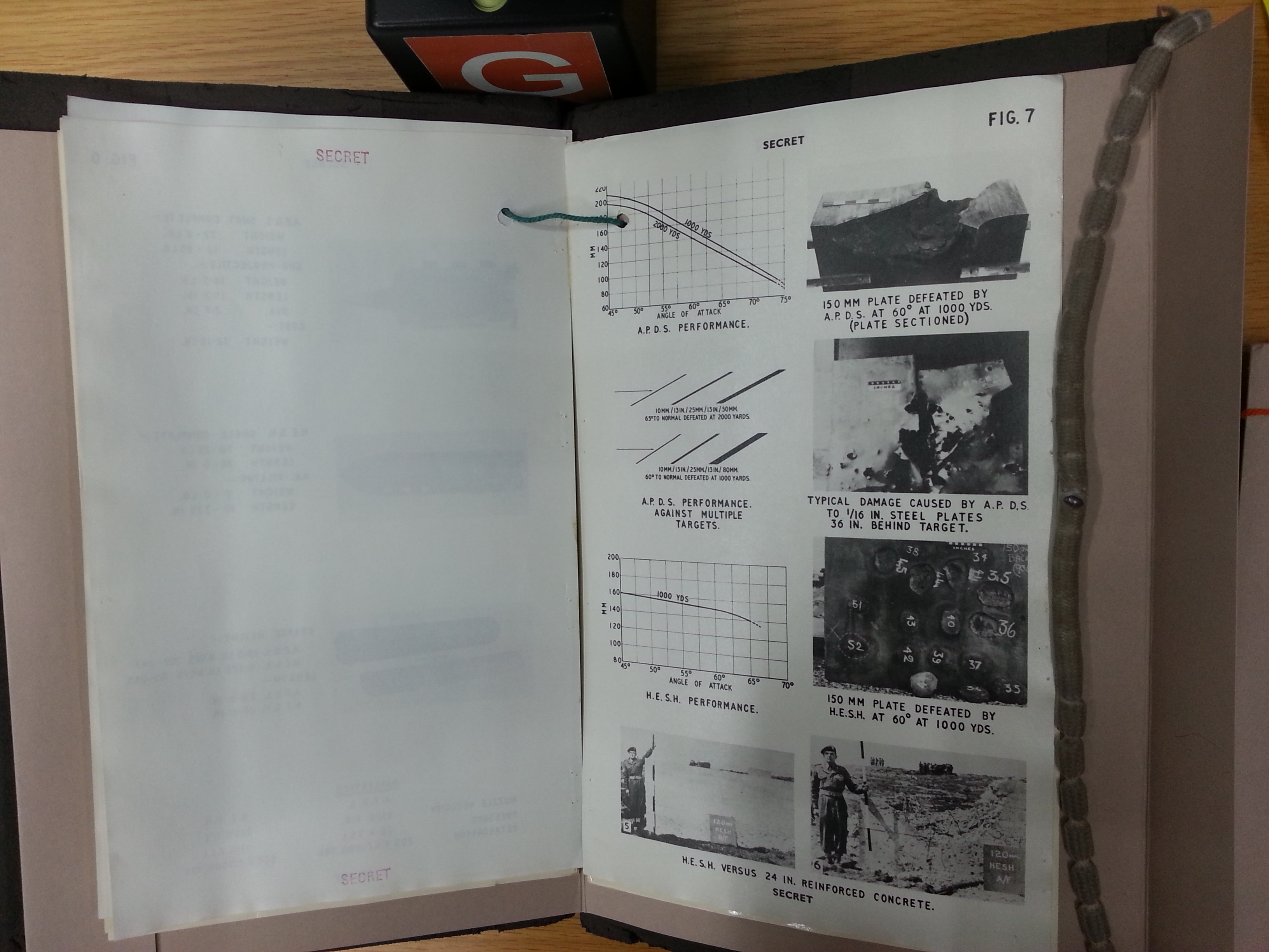

From the graph, it can be seen that at an angle of 64 degrees, L15A5 can confidently defeat a 120mm plate at 1,000 yards but it reaches its limit at 2,000 yards. As such, although the upper glacis armour of the T-10 could still be a challenging target at combat distances, it was altogether insufficiently protected, especially if it was not hit directly from the front but from a side angle. The upper glacis armour of the IS-3 would have no chance against this round at any practical distance and the upper glacis of the IS-4 would also be vulnerable from a distance of 2,000 yards or less despite having a nominally thicker LOS thickness of steel. Only the IS-7 would be completely invulnerable to L15A5 from a 60-degree frontal arc and only from more than a thousand yards away.
Because the standard 20 pdr. and 90mm cannons used by the largest NATO armies (U.K, U.S, West Germany) began to be replaced by the L7 cannon on a wide scale in the early 1960's, it is necessary to explore the level of protection offered from 105mm rounds. The Centurion Mk. 10 entered service in 1959 with the L7 and it could fire L28 APDS rounds. This APDS round was produced under licence in the U.S as the M398 and in West Germany as the DM13, but this round had no chance against the upper glacis of the T-10 even from point blank range. Late APDS designs with a tungsten alloy core and a tilting cap posed a greater threat as they were designed for increased performance on sloped armour. The benchmark model was the British L52 round which was also licence-produced in the U.S as the M728 with minor modifications to the tracer and other miscellaneous components, while the West Germans continued to use the old DM13 round (L28A1 clone) until the DM23 APFSDS round went into service in the early 1980's. The design of the 105mm L52 round for the L7 cannon was largely identical to the 120mm L15A5 round except in scale, so the same slope performance modifiers should be applicable as long as considerations are made for the reduced penetrator to plate thickness ratio.
A drawing from a Swedish Army handbook titled “Arméhandbok del 2” (Army handbook, part 2) that was generously declassified and shared publicly by Ren Hanxue shows that the Slpprj m/66 round (Swedish name for L52A1) fired from the L7 cannon of the Strv 101/102 will defeat 140mm of RHA at 55 degrees from a distance of 1,000 m. Adding on to this, a Spanish catalog page for a 60mm APFSDS round states that 105mm L52 defeats 120mm of RHA at 60 degrees from 1,830 meters. For comparison, the 120mm L15A5 round penetrates 130mm of RHA at 2,000 meters. Using a slope modifier derived from the L15A5 graph to extrapolate the penetration at 55 degrees and 60 degrees to 64 degrees, it appears that the LOS penetration path of L52A1 in RHA declines to below 230mm at 64 degrees at 1,000 m. It should be emphasized that this is good for an APDS round, but it is not enough to defeat the 273mm LOS thickness of the T-10 upper glacis. However, if the "pike" nose of the upper glacis was hit from a side angle of 10 degrees or more, L52A1 may defeat the armour from 1.8 kilometers away. As such, tanks armed with 105mm guns in the mid-1970's would have had little trouble fighting a T-10.
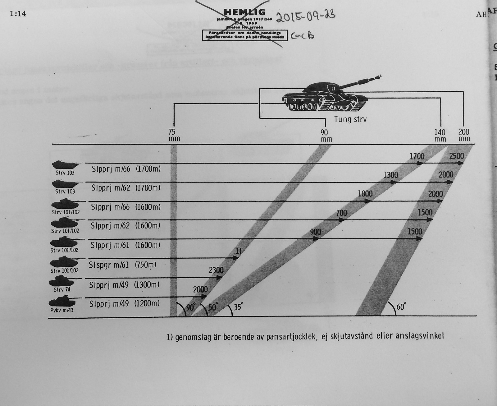
105mm APFSDS rounds would have been a serious threat for any T-10 model, but they came too late to be of any relevance for the T-10 as they only began appearing in the late 1970's. More specifically, there was one APFSDS round in service in the late 1970's: the American M735 round from 1978. The British did not create any APFSDS ammunition for the L7 until the early 1980's and in that instance it was only for export (L64), and the West Germans got their first 105mm APFSDS round in 1982 the form of the DM23.
LOWER GLACIS

Naturally, the lower glacis of the T-10 is less resilient than the upper glacis, so it is a much more attractive target than the upper glacis if it is exposed. Having a plate thickness of 120mm and a slope of 50 degrees, the lower glacis has a LOS thickness of just 187mm and it is only proofed against a comparatively limited variety of armour piercing ammunition, but it is important to point out that the slope angle of 50 degrees was most likely chosen deliberately because the German 8.8cm Pzgr. 39/40 APCBC shell was known to reliably break apart and fail catastrophically on armour plate at impact angles of 50 degrees and above. Full immunity from this round fired from KwK 43 and Pak 43 guns was a basic requirement of the tank along with protection from domestic 122mm shells. Nevertheless, this part of the tank was still be slightly weaker compared to the IS-3 which had a 110mm plate sloped at 55 degrees for a LOS thickness of 192mm and it was also significantly weaker compared to the IS-4 which had a 160mm plate sloped at 40 degrees for a LOS thickness of 209mm.
Given a thickness to diameter ratio (T:D) of 0.6 for a 90mm projectile against the 120mm plate, the 50 degree slope multiplier of 2.05 for an American 90mm APCBC projectile given in page 37 of "WWII Ballistics: Armour and Gunnery" is applicable for the M82 round for the 90mm M36 and M41 guns which armed the M47 and M48 respectively. Against this round, the lower glacis armour would be equivalent to a perpendicular 246mm RHA plate. This is far beyond the capabilities of M82 even at point blank range. With that, the lower glacis is at least proofed against the standard American tank gun of the period.
Testing of the IS-5 with sharp-tipped armour-piercing rounds (BR-471) revealed that the velocity limit of immunity against these shells on the frontal arc of ± 30 degrees was 762 m/s, corresponding to a distance of 400 meters. At this impact velocity, a bulge with a height of 17mm was formed on the back surface of the plate. During tests in 1955, it was found that the velocity limit of conditional defeat of the T-10 lower glacis from the 122mm BR-471B shell (muzzle velocity of 795 m/s) from the direct front was 710 m/s. This corresponds to a distance of around 1,050 meters. Combining these two data points together, the lower glacis is resistant to BR-471 at 400 meters and it should be resistant to BR-471B only at 1,100 meters and above.
The lower glacis has a slope modifier of 2.25 against early APDS and 2.6 against 90mm HVAP, and as such, has an effective thickness of 270mm and 312mm respectively for the two aforementioned projectile types. Based on these figures, the lower glacis armour would be immune to M332 HVAP fired from the M36 and M41 guns only from a range of above 500 yards. However, if the penetration tables from this site are correct, Mk.3 APDS rounds fired from the British 20 pdr. gun would be able to defeat the lower glacis armour from over 2,000 yards away.
The lower glacis is not thick enough to resist 105mm APDS rounds at any feasible distance according to the figures presented in this Swedish armour penetration diagram, available courtesy of Ren Hanxue. From the diagram, it can be seen that both the Slpprj. m/61 (L28) and Slpprj. m/66 (L52A1) fired from the L7 gun of an Strv 101/102 (Swedish modification of the Centurion) will defeat a 120mm RHA plate angled at 38 degrees from the horizontal (52 degrees from the vertical) from more than three kilometers.
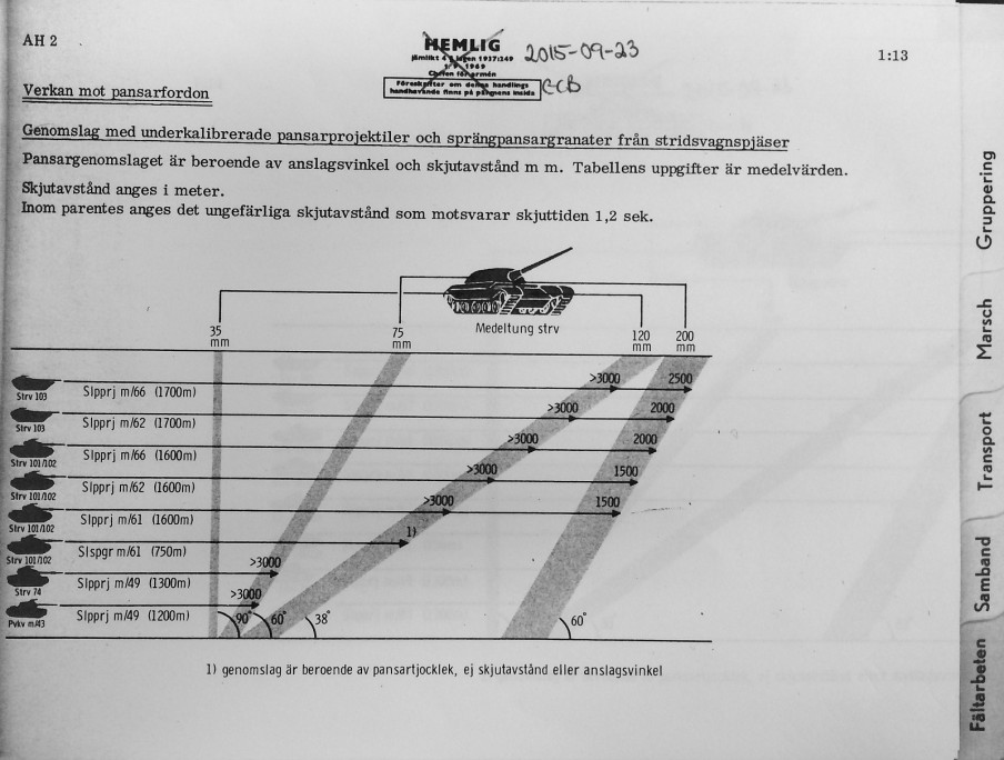
DRIVER'S HATCH

The upper glacis deck has a thickness of 60mm and is sloped at 78 degrees for a total LOS thickness of 288mm. The obliquity of the armour is high enough that most fuzed projectiles from the 1950's will consistently fail to initiate on impact. The driver's hatch has the same thickness and is angled at the same obliquity, but it is made from cast steel instead of rolled steel and has a shallow bulge in the center to increase the driver's headroom. The photo above is from Dave Haskell. If the upper glacis deck is compared to the upper glacis, it appears to be more resilient as it has a higher LOS thickness, and this should be true for HEAT and HESH impacts, but because of the presence of the driver's hatch, the entire area should still be somewhat weaker .
In terms of protection, the driver's hatch theoretically serves as a very sturdy piece of armour with a slope equal to the rest of the upper glacis deck, but it is important to remember that armoured plates that are not rigidly secured tend to have issues with direct impacts from powerful cannons even if the nominal thickness of the plate appears to be enough to deflect the shot. For instance, the driver's hatch of the T-34 was identified as a weakness in combat reports and it remained a weakness albeit a lesser one even after its thickness was increased to 60mm on the T-34 obr. 1941. The issue was that the hatch could be ripped from its hinges or jammed in place even if the shot did not perforate the plate. As such, having the driver's hatch in a position where it is exposed to direct hits on the T-10 created a minor weakened zone in the frontal projection of the tank, and the hole in the hatch for the TPV-51 forward-facing periscope compromises the resistance of the hatch itself to direct hits.
Case in point: after live fire tests of T-10 hulls with 122mm guns were concluded, it was observed that the driver's hatch was consistently dislocated despite never having been hit directly with cannonfire. During tests August 24 to September 6, 1956, the hatch locking mechanism was broken by the initial battery of shells and the hatch lifting mechanism handle fell off. In a real combat situation, the driver would be unable to exit through the hatch afterwards and he would have to evacuate the tank through the belly escape hatch or through the turret. After the fifth shot to the front hull armour, the hatch popped out and it became impossible to close and lock it. After the live fire tests of the armour plate joints, the hatch together with its locking and lifting mechanism was simply torn out. This occurred during all of the tests. Pavlov writes that the durability of the driver's hatch and hatch mechanism was not considered an issue, although he does not elaborate further. It may be that the high number of direct hits required to cause such damage was not considered plausible in a realistic combat scenario.

Based on these results, the T-10 may only be considered completely proofed against guns of lower power such as the 90mm M41 that armed the M48 Patton, the 20 pdr. gun of the Centurion Mk. 3, and the 105mm L7 and M68 that armed many NATO tanks during the 1960's. As established earlier, an attack from the 120mm M58 gun of the M103 would probably fail to defeat the upper glacis armour from combat ranges, but with these test results in mind, it is likely that the colossal energy delivered by the M358 projectile may damage the driver's hatch on the first hit and physically incapacitate the crew as well as disable some internal equipment with multiple hits by shock alone.
The results of possible direct fire tests of the T-10 upper glacis deck and driver's hatch have not yet been published, but the level of resilience can already be appreciated from the available information. Even if the upper glacis deck and driver's hatch armour itself is theoretically capable of stopping a powerful tank shell, debilitating injury to the driver and a subsequent loss of the tank's mobility is quite possible. The T-10 could be considered a downgrade from the IS-3 in this regard as the driver's hatch and upper glacis deck of the IS-3 was much less exposed, as shown in the comparative image below (not to scale). The cost of the IS-3 design was that it had a smaller driver's hatch, among other drawbacks that will be discussed later.

SIDE ARMOUR

The sides of the hull were also tremendously well-armoured, particularly for a tank weighing only 50 tons. Like the front of the hull, this part of the T-10 also left a legacy in the form of the NATO Triple Heavy target which was designed to represent the side armour of a T-10 and it was considered to be the toughest tank armour target to defeat. This target assumed that the T-10 side hull armour was composed of a 10mm high hardness skirt, large mild steel roadwheels with a thickness of 25mm, and an 80mm RHA base armour plate. In reality, the side armour of the T-10 was entirely monolithic, lacked a high hardness skirt, and the roadwheels were also too small to cover the side hull armour.
The sponson upper side armour plate was 120mm thick and sloped at 47 degrees, and the sponson lower side armour was constructed from a single 80mm plate bent outward with a large press to join the hull belly to the sponson side plate. The 80mm plate is sloped at a very steep angle of 62 degrees. These two parts constitute the sponson armour of the T-10, which occupies approximately half of the total height of the hull.
The lower half is much weaker as it consists of the flat portion of the 80mm plate that formed the lower sponson armour, and the bottom half is formed from the belly armour plate which was bent upwards to join with the 80mm plate. The drawing below shows how the armour is distributed. As you can see, the level of protection gradually increases as the height tends towards the turret ring area. At the very bottom of the hull, there is only the empty space underneath the rotating floor of the fighting compartment and the probability of hitting this part of the tank is low, so the rather poor protection offered by the thin plate has a minimal effect on the overall survivability of the tank.

The 120mm upper sponson side armour plate has an effective thickness of 176mm when viewed perpendicularly, but when viewed from a ± 30 degree side angle, the compound angle is 70 degrees and the effective thickness of the armour increases to 352mm. The sloped 80mm plate of the lower sponson armour has an effective thickness of 170mm when viewed perpendicularly, and when viewed from a ± 30 degree side angle, the compound angle is 76.4 degrees and the effective thickness becomes 341mm. This is only marginally less than the sponson side armour and the higher angle of slope is a major compensating factor as the effectiveness of AP and APDS rounds declines exponentially at higher angles of obliquity. Needless to say, the side armour of the hull at such an angle would have been theoretically immune to any AP or APDS round at the time and remained invulnerable even against the newer L15 APDS of the Chieftain main battle tank.
Based on the results of the live fire trials, it was found that the velocity limit of conditional defeat for the lower part of the sponson armour (80mm sloped at 62 degrees) against 100mm blunt-tipped shells (BR-412B, muzzle velocity of 895 m/s) were 790 m/s for the starboard side and 793 m/s for the port side. Postwar firing tables show that these velocities correspond to a distance of 1,000 meters. The velocity limit of conditional defeat for the lower part of the hull sides (flat 80mm) was 483 m/s, corresponding to a distance of more than 4,000 meters.
The lower half of the hull sides is less than half as resilient as the sponson side armour since the plate is 80mm thick but is not sloped at all. This part of the hull has the same protection as the side hull armour of a Soviet medium tank like the T-54. From a 30 degree side angle, the effective thickness of this plate increases to only 160mm.
The hull belly plate at the lowest part of the hull sides is exceptionally thin, having a thickness of only 16mm. It is sloped at 58 degrees for a line-of-sight (LOS) thickness of 30mm, so it would still be sufficient for heavy machine guns, small caliber autocannons and splinters from large caliber artillery shells if it were hit at a perpendicular angle. From the same side angle, the compound angle is 74.6 degrees which increases the effective thickness of this thin plate to 60mm. But even after accounting for the additional protection offered by the overlapping torsion bar housings and the roadwheels from such an angle of attack, the small thickness of the plate is generally not enough to stop serious anti-tank weaponry. The saving grace of this shortcoming is that not much damage can be done if a shell pierces this part of the tank since there is very little behind the plate, and the thick torsion bars and torsion bar housings can absorb much of the shrapnel. Interestingly enough, weak as it is, this part of the side hull armour is still nominally equivalent to the side hull armour of the AMX-30 and Leopard 1 in LOS thickness (30mm), but it may be more effective since the penetration of power of bullets and shell splinters degrade drastically on oblique plate.
However, it is worth mentioning that there was a serious caveat to this tremendous level of protection; it was found during live fire testing that the hits of 100mm APBC and HE-Frag shells into the sides of the hull usually split the welds joining the torsion bar housings to the lower side of the hull and the welds attaching the flanges of the support rollers to the side of the hull, and destroyed the closest torsion bar housing and support rollers. The test did not include a full set of roadwheels and tracks as the test was designed to evaluate the structural condition of the tank and not the practical level of protection, but it could be surmised that if the suspension was configured normally, the track would be severed by a shell ricocheting off the sponson lower side plate due to the high obliquity of 62 degrees. Either way, some degradation of the mobility of the tank can be expected from the destruction of one or more suspension elements. So although the side armour of the T-10 could withstand serious punishment, it is quite likely to suffer a mobility kill when powerful anti-tank cannons are fired at its side.
It is worth noting that at a ± 30 degree side angle, one side of the upper glacis "pike" loses 30 out of its 40 degrees of horizontal slope which makes it a wider target while also reducing its effective thickness down to only 258mm whereas the other side of the upper glacis "pike" gains 30 degrees of additional slope but becomes such a narrow target that the area of its projection is negligible compared to the area of the rest of the tank. From the same side angle, the lower glacis armour gains an additional 30 degrees of slope which increases its effective thickness to 216mm. This is not much compared to the colossal thicknesses that are normally encountered on other parts of the tank, but it is still a formidable thickness of armour and it is nominally thicker than the upper glacis of the T-54. Even at this inopportune angle, the majority of the profile of the hull is still completely immune to L1G APDS from at least 1,000 yards or less.
REAR ARMOUR

The rear of the hull is very thinly armoured in comparison with the front. The transmission access panel at the rear of the hull has a thickness of 50mm and is sloped at an angle of 40 degrees for a LOS thickness of just 65mm. The angle of slope was increased to 55 degrees on the T-10M (LKZ) for a LOS thickness of 87mm. The lower rear hull plate is 60mm thick with a slope of only 20 degrees for a LOS thickness of 64mm, and remained unchanged in all models. This was a reduction from the IS-3 and IS-2 which had 60mm plates sloped at 48 and 41 degrees on the top and bottom halves of their rear hull plates respectively, but it was already enough to resist shelling from medium caliber autocannons.
The rear hull armour of the IS-4 was simply excessive by comparison, having 100mm plates sloped at various angles from 32 to 39 degrees for a maximum LOS thickness of 128.7mm; twice the LOS thickness of the armour plates of the T-10 at the same locations. For the T-10, having half as much armour at the rear of the hull also halved the weight and the tank could benefit in other aspects without suffering any real loss in protection from a practical standpoint, as the fact of the matter is that direct hits to the rear of the hull from anti-tank weapons were rather rare even when tank combat distances were limited to just a few hundred meters. According to the data presented in the report WO 342/1 detailing the distribution of hits on American tanks during the Korean war, of the 57 hits whose position are known, 35% were on the front of the tank, 60% were on the sides, and 5% on the rear. Data from WWII tank battles shows a similar distribution of hits.
In the unlikely event that the tanks is attacked from the rear, even the huge thickness of armour on the rear of the IS-4 would be insufficient to deal with the 75mm and 76mm guns of the AMX-13 and M41 Walker Bulldog light tanks, not to mention infantry-portable HEAT weapons like the M20 "Super Bazooka" which had enough penetration power perforate the rear hull armour of an IS-4 twice over. Infantry-portable weapons were particularly relevant as a heavy tank could be attacked from the rear with such weapons after rolling past enemy fortifications, but both the T-10 and IS-4 would only be capable of resisting a glacing hit if either tank were attacked from this direction.
However, an examination of the hull cannot end here. Besides the sturdiness of the armour against direct-fire weapons, some attention must be directed at its resistance to mines as well.
BELLY ARMOUR (MINE PROTECTION)

Unfortunately, there is a lack of information on the resistance of the T-10 to mine attack, but the sturdiness of the stamped hull belly is not particularly reassuring as it has a thickness of only 16mm. The belly underneath the transmission is even weaker, having a thickness of only 12mm and being completely flat unlike the remaining three quarters of the hull where the belly is shaped like a trough. This is only twice as thick as on a typical armoured personnel carrier and it would be considered abnormally weak for a tank if the rest of the belly were this thin. However, this is acceptable in the sense that differentiated armour thickness is used to mitigate weight gain, as the rear of the hull belly is very unlikely to receive a mine blast compared to the front of the hull belly. To improve the rigidity of this area, additional longitudinal and lateral ribs were stamped into the belly plate underneath the transmission beginning with the T-10M.
On the T-10M, the belly plate is a single long plate stamped into a trough shape. It is unclear if the same method was used to form the belly of preceding models, or if they were made from separate plates welded together.
This shape does not qualify as a bona fide "V" belly that is common among modern mine-resistant armoured vehicles, but the trough shape has a similar effect in that the sloping edges direct the blast wave of an underbelly explosion towards the sides and it increases the rigidity of the belly structure as a whole.
It is also necessary to take the cylindrical torsion bar housings that protrude beneath the hull belly into consideration. Because around half of the torsion bar housings protrude outside the hull, the bottom half of the housing had to be thickly armoured and there is an external "waffle" pattern ribbing to increase rigidity. The thickness of the exposed parts of the cast torsion bar housing is the same as the hull belly itself and the cylindrical shape together with the "waffle" pattern ribbing makes it more resistant to deformation. Rather than compromising the rigidity of the hull belly, the presence of the torsion bar housings most likely reinforces it, and indeed, in part 10 of the "Отечественные Бронированные Машины 1945-1965" series of articles authored by M.V. Pavlov and published in the March 2009 edition of the "Техника и вооружение" magazine, Pavlov mentions that the torsion bar housings increase the rigidity of the hull belly. That said, although rigidity reduces the likelihood that structural deformation interferes with the normal function of components, rigidity is by itself not a positive attribute in terms of the resistance of the belly to being breached by blast.


The belly is ostensibly well-protected from mine blast due to its trough shape, previously implemented on the T-54. Executed properly, this shape drastically increases the resistance of a tank hull belly to a mine blast occuring underneath the tracks, with full or partial track overlap over the diameter of the mine. However, in the case of the T-10, the edges of the trough belly shape are far too long, and as a result, the sides of the belly receive shockwave of a mine blast underneath the tracks at an incident angle close to normal. The only positive aspects of this design are that the side surfaces of the belly are distanced further from the ground and from the track, where a mine blast occurs, and that the design may have a partial effect on reducing the severity of a mine blast directly underneath the belly, as the flat center plate of the belly is narrowed due to the trough shape, and thus, the probability of a blast directly underneath the flat zone is somewhat lessened. The width of the sides of the trough-shaped belly is 400mm on each side.
The results of experimental and theoretical analyses on the resistance of the T-10 belly to mine blast damage were presented in the 1969 No. 5 issue of the "Вестник Бронетанковой Техники" journal, in the article "Пути Повышения Противоминной Стойкости Днища Танков". It was noted that the main shortcomings of the T-10 belly design are the low thickness of the belly plate, large surface area of the sloped side projections, the intrusion of the large torsion bar units in the belly plate, as well as the great length of the weld seams connecting the torsion bar units to the belly plate.
The results of experimental and theoretical analyses on the resistance of the T-10 belly to mine blast damage were presented in the 1969 No. 5 issue of the "Вестник Бронетанковой Техники" journal, in the article "Пути Повышения Противоминной Стойкости Днища Танков". It was noted that the main shortcomings of the T-10 belly design are the low thickness of the belly plate, large surface area of the sloped side projections, the intrusion of the large torsion bar units in the belly plate, as well as the great length of the weld seams connecting the torsion bar units to the belly plate.
When an anti-tank mine with a 9 kg TNT charge detonates underneath a track with a partial overlap over half of the diameter of the mine, with the other half exposed to the inner side of the track facing the hull belly, there will be a probability of ~0.5 that the T-10 belly will be breached by the blast. In the best case scenario, to survive a 9 kg TNT mine, the mine must be covered by the track by more than half of its diameter at the moment it detonates. With full track overlap, a mine weighing 12 kg is required to breach the hull. In the worst case scenario, where weld seams are exposed to the blast, the resistance of the belly is drastically less. Even with full overlap of the track on the mine, the welded portion of the belly does not survive a blast of only 6 kg. For comparison - with full overlap of the track on the mine, the T-55 belly requires a 12 kg TNT charge to breach. Without track overlap, a charge of approximately 7.5 kg TNT is required to breach the hull in an underbelly blast. This is shown in the graph on the right in the image below. The y-axis is the weight of the TNT charge, the x-axis is the distance from the track (negative is inward to the hull, positive is away from the hull). The graph lines represent the thickness of the belly plate, with the dashed line represented the welded portion.

It was calculated that overall, the probability of dangerous damage to the belly of a T-10 tank from a 9 kg TNT mine is 1.66 times higher than the probability of dangerous damage to the belly of a T-54 or T-55, accounting for the probabilistic nature of a mine detonating under a zone of the track where it causes the required severity of damage.
Besides the structural issues of the belly design, the armour itself posed an issue, as a thickness of 16mm is noticeably less than the belly of the T-54 medium tank (20mm) and the M60A1 main battle tank (19mm), although is effectively the same thickness as the British Centurion medium tank, Conqueror heavy tank, and Chieftain main battle tank. American tanks like the M103 and M48 are in a class of their own in this category as they have double the thickness of belly armour with additional reinforcement on the very front end of the belly to increase the total thickness to 38mm. This, combined with the rounded shape of the hull belly, made these tanks unmatched in mine protection as the M48 proved in Vietnam.
The British heavy, medium and main battle tank were all designed under the same requirement of surviving a 20 lb anti-tank mine (usually represented by a Mk. 7 mine) underneath the track, and the Centurion tank is known to be incapable of surviving a partially-buried 20 lb mine detonated directly underneath the belly based on declassified reports. Compared to this, the T-10 belly only matches this protection level in the best case scenario, where the mine does not breach weld seams, but in the best case scenario, the resistance of the T-10 belly is significantly higher. It is worth noting that on these British tanks, the only design solution used to improve mine resistance was to slope the hull sides inward, thereby distancing the welded connection between the side and belly plates further from the track.
As a side note, the hull roof over the crew compartment had a thickness of 30mm, but the thickness of the various roof panels covering the engine compartment is only 16mm.

A major impetus for the development of the Kirovets-1 that eventually led to the IS-3 was a tank vulnerability study commissioned by Gen. Nikolai Dukhov. The study found that the most common cause of serious heavy tank losses was hits to the turret, followed by hits to the front of the hull. This prompted the design of a turret with a radically new ballistic shape with a heavy emphasis on armour obliquity, as a result of which the level of armour protection was doubled over the IS-2 turret design. The T-10 turret represents another step forward from the IS-3 design with a more optimal ballistic shape and thicker armour. It is sometimes mistaken for the turret of the IS-3 from some perspectives, but the resemblance is purely superficial as the overall shapes and the curvature of the armour were completely different. However, just like the IS-3 turret, the length of the T-10 turret did not exceed the width of the hull, and because of this, the area of the front projection of the tank did not increase in size when the turret was turned to the side as the photo below (of a T-10M) shows, and therefore, the probability of being hit by incoming fire would not increase. Although this seems trivial, the considerable increase in the projected area of tanks with large turret bustles was a real disadvantage in a combat situation.

The T-10 turret is constructed from two pieces: the main structure is a large single-piece casting with a slightly curved cast plate welded on top to form a part of the turret roof. The turret weighs 6,500 kg in metal alone. MBL-1 grade steel was used for the turret. It is a softer steel compared to the 70L and 71L grades used for IS and T-34 turrets during WWII because the softer but tougher MBL-1 provided more protection against full-caliber armour-piercing shells. The drawing on the left below shows the turret of the basic T-10 and the drawing on the right below shows the turret of the T-10A. The T-10B shares the same turret with the T-10A. The T-10 and T-10A turrets share the same shape, same distribution of armour thickness and provide an almost identical level of protection.


The T-10 turret also abandoned the bolted access panel over the cannon breech assembly that could be found on the turret roof of the IS-3 and IS-4. This made the area much more resistant to direct hits and gave the turret greater structural rigidity with the minor downside that it was no longer possible to remove the cannon from its mount without lifting the turret off the hull. Instead of a bolted access panel, the same area on the T-10 turret roof was solid cast steel with a thickness of 40mm sloped at 85 degrees, and the welded turret roof plate at the rear half of the turret has a thickness of 30mm.
In December 1954, the roof of the turret was changed after tests were carried out earlier in the year. The triangular weld-on turret roof plate was replaced by an oval-shaped plate of the same thickness. This improved the overall structural strength of the roof against cannon fire. All T-10 turrets produced after December 1954 had this new turret design, and it carried over to the T-10A and T-10B turrets as well.
Both the T-10 and T-10A turrets share an almost identical oblong embrasure for the coaxial machine gun next to the embrasure for the main gun. The T-10 has the TSh2-27 sight with an articulating head portion so the embrasure in the turret for its aperture window is oblong in shape and quite small. The T-10A and T-10B with the TUP-21 backup sight is mounted directly onto the D-25TS cannon and lacks an articulated head and as such, a narrow but long vertical slit had to be cut into the turret instead.
On the whole, the T-10 turret is somewhat similar to the T-54 obr. 1949 turret in general shape, except with a more pronounced vertical curvature on all surfaces. From the side, the turret bears a strong resemblance to an egg halved along its longitudinal axis, but from the front and rear, the turret appears to be shaped like an isosceles trapezoid. The shot trap formed by the curvature of the IS-3 turret cheeks was also eliminated by the T-10 turret which had an almost completely convex design, lacking any surfaces from which an impacting shot could potentially ricochet into the turret ring or onto the hull roof. This was not an insignificant improvement considering that AP, HVAP and APDS rounds were still the primary anti-tank munitions carried by the tanks of the probable enemy at the time. The closest equivalent to this development is the progression of the Pz.V "Panther" gun mantlet design from the Ausf. A/D scheme to the Ausf. G scheme with the flattened lower edge.
According to Mikhail Kolomiets, the front of the turret had a thickness of 275mm to 250 mm, the sides were 157mm to 102 mm thick, and the rear had a thickness of around 90 mm. The front armour thickness figure refers to the thickness of the cheek from a side angle of 30 degrees, rather than from the direct front. As with practically all complex cast turrets, it is extremely difficult to find a reasonably accurate description of the distribution of thicknesses and angles of slope, and it is harder still to distill the true qualities of the armour in text. The biggest challenge lies in the sloping of the armour in two planes. This severely complicates calculations and introduces further variances in armour effectiveness depending on the angle of impact. Based on a review of all available sources, it appears that the most commonly reported thickness figure for the T-10 turret is 250mm, but the compound slope of 20-30 degrees at cheek region affects the protection value.

In terms of thickness alone, the T-10 turret does not surpass the IS-3 which had a maximum physical thickness of 249mm at the turret cheeks, but after tests in 1955, it was concluded that the T-10 turret had greater structural strength than the IS-3 turret and was also more resilient. This was most likely because of the use of a better type of steel and improved casting technologies.
Besides the base armour thickenss of the turret front, it is necessary to also examine the gun mask that covers the embrasure for the main gun. The photo on the left below, by Pavel Lusta, shows the gun mask of an original T-10 while the drawing on the right below shows the gun mask of the T-10A and T-10B. The only real difference is that the former has an embrasure for the TSh2-27 sight whereas the former has an embrasure for the TUP-21 sight. Both gun masks are rounded in shape.


The gun mask is attached to the front part of the D-25TA and D-25TS gun breech assembly with large bolts and buffered with thick rubber bushings for shock absorption. The size of the embrasure in the turret is no wider than the gun breech assembly, and it is slightly shorter in height. The photos below show the small size of the embrasures in the turret for the coaxial machine gun and the TSh2-27 sight. The replacement of a traditional gun mantlet such as on the T-34, T-34-85, T-44, and IS-2 turrets with a narrow embrasure coupled with an armoured gun mask was a feature that the T-10 shared with postwar Soviet tanks like the IS-3, IS-4 and the T-54 obr. 1949 as this type of construction solved a plethora of structural issues, had a reduced likelihood of jamming from direct hits, and improved the protection of the turret as a whole.


The armour of the gun mask varies in thickness and overlaps with the turret base armour, but overall, the area covered by the gun mask reaches a similar level of protection as the turret cheeks from a frontal attack and does not exceed it because the base turret armour has two weakened zones. One of them is the edges of the embrasure which have a reduced armour thickness owing to the need to accommodate the trunnions for the gun cradle. The trunnion is marked (1) in the drawing on the left below. As the drawing on the right below shows, the gun mask overlaps with this area and more than doubles the total thickness. The armour thickness reaches its maximum at the base of the turret where the trunnion mounting pins are secured into the turret, marked (2). These pins run through the entire thickness of the turret, so they qualify as another weak point in the armour as a direct hit on the head on the pin might push it out and into the interior of the turret. Fortunately, they are extremely small relative to the overall size of the turret - the surface area of the pins occupy less than 0.5% of the total surface area of the front projection of the turret. The heads of these two pins can be seen from outside the tank if the gun mask is removed like in the photo on the right above.


The variable thickness of the gun mask reaches its maximum in the area directly in front of the gun breech assembly, as this part is otherwise unprotected by the turret armour. The thinner edges of the gun mask extend outward to cover the vertical slots cut into the turret for the coaxial machine gun and the coaxial telescopic sight. The maximum width of the gun mask is 835mm.
At the rear of the turret, there is small gap between the turret ring and the wall of the turret bustle. Unlike the M103 and Conqueror turrets which had a large shot trap built into their turret bustles, this gap in the bustle of the T-10 turret is simply a zone of greatly reduced armour thickness. The thickness of the thin floor plate joining the turret ring to the walls of the turret bustle in this gap is not known, but based on the drawing below, it appears to be half the thickness of the hull roof (40mm), so it should be around 20mm. To reduce the vulnerability of this zone, an additional curved armoured rib welded to the underside of the floor plate to act as a spaced armour screen beginning with the T-10A turret. The ideal design would omit gaps and shot traps like the turret of the IS-3, but in this case, the height of the gap is small enough that it is an extremely minor chink in the turret armour.

Given that the sides of the turret appear to be set at the same angle as the upper side hull plates (47 degrees), the armour at the widest point - next to the commander's station and loader's station - should be set at this angle.
The turret ring race ring is recessed below the surface of the hull roof and there is a set of interleaved rings to seal the gap from bullet splash. To further reduce the probability of a jammed turret, the hull armour plates on the front and sides have a lip with a height of around 27-35mm that covers the small gap between the base of the turret and the surface of the hull roof. It's rather unlikely that this lip is enough to stop a cannon shell, but it is more than enough to reliably keep out heavy machine gun bullets and shell splinters and it may also be enough to resist direct hits from a 20mm autocannon.

These details are represented in the drawing below.

The interleaved rings around the circumference of the turret ring are clearly shown in the drawing below.


To help control the weight gain from the new features added in the Chelyabinsk T-10M (Object 734) without significantly compromising the protection level of the tank, the thickness of the welded turret roof was reduced from 30mm to 20mm. However, the Leningrad T-10M (Object 272) retained a welded turret roof with a 30mm thickness, and the constructional turret roof had its thickness increased from 40mm to 50mm without changing the angle of slope of 85 degrees. Given that the Object 272 became the standard T-10M design for serial manufacture in both ChTZ and LKZ since 1962, it can be considered the de facto model.


Although there were some changes in the shape of the front of the turret, the basic design was more or less unchanged. At the front of the turret next to the gun barrel, the base of the turret has a thickness of 250mm. Physically, this is the thickest section of armour found on the entire turret, but it is completely flat in the horizontal plane. As the turret curves upward to form the roof over the gun breech, the thickness is reduced to 200mm with a vertical slope of 24 degrees, and then transitioning to 135mm with a slope of 49 degrees. Based on these simple figures alone, it appears that the line-of-sight (LOS) armour thickness reduces along the height of the turret, but this is only because the horizontal slope of the turret is completely ignored.

Like the T-10 and T-10A turrets, the edges of the embrasure in the T-10M turret also had a reduced thickness to accommodate the trunnions, marked (2) in the drawing below. The trunnions and the trunnion mount was of a different, more robust design, but the modified trunnions were still secured to the turret using pins, marked (1) in the drawing below.

The trunnion was moved forward relative to the trunnion mounting pins to reflect the different center of gravity of the M62-T2 cannon. Indeed, the entire cannon breech assembly was mounted slightly further forward in the turret, but the thickness of the armoured gun mask was not increased. On the contrary, the overall thickness of the gun mask was significantly reduced to only around 100mm and the amount of protection that it offered was considerably lower. However, the diameter of the M62-T2 gun tube was larger without a corresponding increase in the size of the embrasure, so proportionately speaking, this part of the gun mask of the T-10M covered a slightly smaller surface area and constituted a smaller weakened zone.


Like the gun masks of previous T-10 models, the gun mask on the T-10M turret was attached to the end of the M62-T2 gun by four large bolts, and like the earlier gun mask designs, the T-10M gun mask has a maximum width of 835m, but the shape of the gun mask was changed. Now, it is no longer rounded but was instead semi-cylindrical as the photo below shows.

The lowest edge of the gun mask is flat in the vertical plane but retains the same 24 degrees of horizontal slope.


The two photos below show the T-10 turret with the gun mask removed. The photo on the right below (from Carrey on Primeportal.net) gives a closer view of the four large bolt holes which are used to mount the gun mask onto the M62-T2 gun.


The photo below (from Mikhail Baryatinsky) shows two T-10M tanks being prepared for scrapping. The size of the embrasure for the main gun can be clearly seen.

The thickness of the T-10M turret next to trunnion mounting pins is 250mm. This zone is the only part of the turret that could be considered close to flat as there is only 16 degrees of horizontal slope with no vertical slope. Overall, the level of protection offered by the T-10M turret is equivalent to the T-10 turrets produced from 1955 to 1956 and onwards.
The rear of the turret also remained at the same level of protection. The base of the bustle had an armour thickness of 102mm at a flat angle, thinning down to 68mm at an angle of 54 degrees. Combined with the curvature of the turret in the horizontal plane, the armour above the 102mm belt at the base of the bustle is theoretically enough to withstand full-caliber armour-piercing shells from a 57mm high velocity cannon from any range.
The gap at the base of the turret bustle remained, but the bustle floor plate joining the turret ring to the walls of the turret bustle changed in design. The floor plate in the T-10M turret extends away from the turret ring before sloping upwards to join with the walls of the turret bustle, thus creating additional internal space without adding weight. The curved armour rib welded to the underside of the floor plate was removed, but the level of protection did not change because of the slope of the floor plate. The reason for this change was to accommodate the new ammunition stowage scheme.

The protection of the hull sides against shaped charges was considered insufficient as the frontal arc of immunity against contemporary HEAT weapons was too narrow. For the PG-2 grenade with an 82mm warhead fired from the RPG-2 (rated penetration of 180mm RHA), the maximum angle of attack where the armour remained immune was just ±26 degrees, meaning that a PG-2 grenade would only fail to perforate the armour when the angle of impact is 26 degrees off from the perpendicular axis in either direction. For the PG-82 grenade with an 82mm warhead fired from the SPG-82 (rated penetration of 175 mm RHA), the maximum angle of attack was ±27 degrees. For the VBK-881 grenade with an 82mm warhead fired from the B-10 recoilless gun (rated penetration of 250mm RHA), the maximum angle of attack was ±22 degrees. For the VBK-883 grenade with a 107mm warhead fired from the B-11 recoilless gun (rated penetration of 290mm RHA), the maximum angle of attack was ±20 degrees.
For a 76.2mm HEAT shell of unknown type, presumably the BK-354M round for the D-56T gun of the PT-76, the maximum side angle was ±21 degrees. For an 85mm HEAT shell of unknown type, presumably the 3BK-7М round for the D-48 and D-70 anti-tank guns, the maximum side angle was ±15 degrees. However, keep in mind that all of these figures are only for the lower side hull armour which is a flat 80mm plate. As usual, the Soviet criteria for tank protection was extremely strict and only the least protected portion of the side hull projection was considered. If a less pessimistic perspective were adopted instead, it is obvious that the upper side hull armour of 170mm to 176mm would have a decent chance of resisting a shot from an RPG-2 or an SPG-82 at a flat angle. Even against the 85mm HEAT round which had the most potent warhead of all the types tested, the maximum side angle of immunity for the upper hull sides would be around ±56 degrees, so the frontal arc of immunity would be 112 degrees.
The M371A1 HEAT round fired from the 90mm M67 recoilless rifle penetrated 250mm of armour plate, and the warhead of the M72 LAW (from original up to the A3 model) penetrated 200mm of armour. The original M28 HEAT rocket for the M20 Super Bazooka penetrated 265mm of armour and the newer M35 rocket penetrated 280mm of armour. It is worth noting that the penetration power of all of these weapons deteriorated somewhat on sloped plate due to fuzing issues. These weapons were enough for the frontal armour of a T-34 or even a T-54, but generally speaking, man-portable recoilless rifles and rocket launchers lacked sufficient penetration power to defeat the armour of the T-10 from the front unless the lower glacis armour was hit. The turret could be defeated more easily than the upper glacis, but the rather low overmatch would only result in minor internal damage. Nevertheless, the T-10 was clearly not immune to such weapons, and that fact alone is worrying.
Larger crew-served weapons like the 106mm M40 recoilless rifle were capable of handily defeating the armour of the T-10 from the front. The M344 HEAT shell penetrates 433mm RHA which gives it an overmatch factor of 100mm against the upper glacis armour, making it an effective countermeasure against the T-10. Nevertheless, the T-10 was still noticeably better protected in this regard compared to its direct counterparts the American M103 and the British FV214 Conqueror. The upper and lower glacis armour of both of these tanks could be pierced by the PG-7V round fired from an RPG-7 which had 260mm of penetration with the basic PG-7 grenade, and the BK-833 round fired from the crew-served 107mm B-11 recoilless gun had 381mm of penetration which is more than enough to pierce the hull armour of both tanks at any location.
Based on a simple comparison of the LOS thickness of armour and the penetration power, the upper glacis of the T-10 is ostensibly incapable of resisting the 90mm M431 HEAT shell fired from the M36 and M41 guns of the M47 Patton and M48 Patton respectively, and it appears to be completely insufficient against the 105mm HEAT rounds of the L7 such as the M456. However, there are serious caveats - during ballistic tests conducted in Yugoslavia, it was found that 90mm M431 HEAT shells (with the M509A1 fuze) failed to fuze on the upper glacis armour of a T-54A if the tank hull was angled 20 degrees sideways. The resulting compound angle is only 62 degrees but this was apparently sufficient to cause a fuzing failure. It can be expected that the 105mm M456 would perform just as poorly as it uses the same M509 fuze as the M431.
Because additional angling was required to achieve this effect, this would only count as circumstantial protection for the T-54, but for the T-10 which has a structural 40 degrees of horizontal slope on its upper glacis, a 90mm or 105mm HEAT shell would need to impact the upper glacis from a side angle of at least 36 degrees in order to simply fuze properly, and conversely, the upper glacis of the T-10 would be capable resisting these shells in a 70-degree frontal arc with the same consistency displayed in the Yugo trials. As such, HEAT ammunition for M47, M48 and M60A1 tanks cannot be considered reliable countermeasures against the T-10 hull. The issue with fuzing on highly oblique targets was only remedied in the early to mid 1980's with the M456A2 and 105mm DM12 HEAT rounds. However, the turret of the T-10 would be more vulnerable, especially at its gun mask area. Only the edges of the turret would have a sufficient line of sight thickness to resist HEAT shells as well as a sufficiently steep angle of obliquity to cause fuzing issues.
The Yugoslavian test results were not a isolated cases. During the Korean War, it was found that M6 Bazookas and M20 recoilless rifles were ineffective against North Korean T-34 tanks despite having a nominally sufficient penetration power to go through the thickest parts of the tank. The issue was that the all-aspect sloping of the hull of the T-34 resulted in frequent fuzing failures, so the warheads simply failed to detonate or they detonated with a significant delay, causing the shaped charge to impact the armour from a very short standoff distance. Broadly speaking, fuzing issues were likely to occur if the angle of impact exceeded 60 degrees.
The issues with fuzes during the early years of the Cold War were noted by both sides and sometimes led to interesting creations. Indeed, the well-rounded hull of the famous Object 279 depended on the low fuzing reliability of HEAT shells as the primary defense mechanism. By having additional angled inserts added on top of the cast steel hull to increase the relative slope of the armour, Soviet engineers were able to greatly reduce the vulnerability of the tank to HEAT shells without raising its weight to an impractical level. These inserts were rather lightweight so they were not sturdy enough to act as armour against solid shot AP or APDS projectiles, but were just thick enough to ensure that the fuzes of HEAT shells could not pierce the skin and would instead be deflected and destroyed, thus causing the shell to fail to initiate on impact.
Graze-sensitive fuzes for anti-tank missiles would not suffer from the same issues. Such devices began appearing in the early 1970's and would have been an effective means of defeating the T-10M as it was still in service and would likely have routinely faced NATO anti-tank missile platforms owing to its high priority as a heavy tank. Furthermore, the M456A2 and its West German licence-produced clone the DM12 were no longer susceptible to fuzing issues on highly oblique targets as a new fuze, known as the full-frontal area impact switch (FFAIS), was installed.
The high obliquity of the upper glacis armour may also useful against HESH or HEP rounds in certain circumstances as it is high enough to be more useful than harmful, but still, the thickness of the armour is insufficient against HESH rounds larger than 90mm in caliber. Moreover, the high obliquity of the T-10 armour may be rather useless if it is attacked from a very long range as the arcing trajectory of HESH rounds - which are slow by nature - will tend to impact at a diving angle.
In a Soviet document titled "Воздействие 106-мм Бронебойно-Фугасных Снарядов Безоткатного Орудия На Монолитную Стальную Броню", it is reported that the M346 projectile, which has a diameter of 105mm and contains 3.25 kg of Composition A3 but lacks an inert nose cap, is capable of defeating a 120mm plate at 65 degrees. Cannon-fired 105mm HESH rounds should achieve the same result. Needless to say, 120mm HESH is easily capable of defeating a 120mm plate as the graph below shows.

However, it must be understood that HESH rounds were not necessarily an effective counter to T-10 tanks as the effectiveness of any given type of ammunition does not hinge entirely on the ability to defeat the armour of the target. It is certainly an integral component of the equation, but it is not the only factor. For HESH rounds, the primary factor that hinders its ability to serve as an effective weapon against T-10 tanks is their poor ballistic performance. Due to the plethora of technical constraints associated with the proper function of squash head warheads, HESH shells must be launched at a low muzzle velocity of around 600 m/s, not more. Combined with the poor aerodynamic form of the HESH projectile, which is another technical constraint related to the squash head design, the ballistic trajectory of HESH shells is extremely pronounced and the shell is extremely sensitive to deflection by crosswinds despite their characteristically high mass.
As the graph on the left below shows, a HESH (HEP) shell takes a significantly longer time to reach the target compared to four other types of armour-piercing ammunition and has an extremely arced ballistic trajectory. The long flight time makes it much more difficult to hit a moving target. The graph on the right below shows the effect of a 10 m/s crosswind on the deflection of three types of armour-piercing ammunition. APDS rounds are the least affected, making them much easier to use, especially for early Cold War tanks that lack a crosswind sensor, whereas HESH rounds are severely affected by crosswinds.


Even with a suite of sensors and a ballistic computer that can handle a variety of environmental factors, modern tanks firing HESH shells still have a notably worse probability of hit on tank targets, especially moving targets. Needless to say, tanks such as the M60A1 will find it extremely difficult to use HESH rounds against moving T-10 tanks at long range, whereas most T-10 models that an M60A1 would encounter will tend to have a stabilized gun that can deliver effective return fire, and although Chieftains have a stabilizer, there is no reason for them to use HESH rounds when they have L15 APDS rounds that facilitate a higher probability of hit and have sufficient penetration power to defeat the frontal armour of any T-10.
The PPO firefighting system came standard on the T-10. This was an automated system that was controlled by the driver with two modes of operation: the 'automatic' mode, or the 'semi-automatic' mode. Three carbon dioxide fire extinguisher bottles were provided and each would be expended in a single powerful burst with each activation. The fire extinguisher bottles were placed behind and to the right of the driver's seat.
In the 'automatic' mode, the system alerts the driver of the source of the fire, shuts off the engine, and cuts off the engine air intake. Then, one of the three fire extinguisher bottles are activated and the entire compartment is flooded with the extinguishing agent. In the 'semi-automatic' mode, the system alerts the driver of the presence of a fire via an audio alarm and a signal light, but takes no action on its own. The driver can then choose whatever action he deems most suitable at the moment. He can control the system from his station and choose to activate any number of bottles.
Six TD-1 temperature sensors were placed in strategic locations around the engine compartment and oriented at the most probable source of potential fires. The system reacts to a rise in temperature to 180 degrees Celsius and has a response time of 10 seconds. The long response time is due to the inherent limitations of the use of thermocouples as temperature sensors. Naturally, the oxygen content in the engine compartment is quite low due to the high concentration of carbon monoxide and fumes so fires tend to be easier to extinguish as they are already facing partial oxygen deprivation, but fires cannot be detected instantly due to the limitations of the sensors and the lack of any other feedback system to alert the crew, so the fire has more time to spread and this makes it much more difficult to extinguish.
Because the PPO system only protects the engine compartment, fires in the fighting compartment must be handled manually by the crew using two carbon dioxide OU-2 hand-held fire extinguishers to extinguish fires. The fire extinguishers are placed on the front right corner of the fighting compartment and are most easily reached by the driver, but the loader is able to access them as well. Carbon dioxide is suitable against Class B and C fires, namely fuel and electrical fires, which are the predominant causes of fire in a tank. Although it is not as poisonous as carbon monoxide, carbon dioxide can cause asphyxiation by hypoxia and it is is toxic in high concentrations, so it is unsafe to remain inside the tank after the extinguisher bottles have been discharged.
In 1964, the "Rosa-2" firefighting system was installed on new T-10M tanks and it began to be retrofitted to older tanks. Like the older system it replaced, "Rosa-2" only covers the engine compartment. The main improvements of "Rosa-2" was in the speed and reliability of extinguishing fires compared to the PPO system. This was achieved by using a halocarbon fire extinguishing agent designated "3.5"; a pressurized combination of ethyl bromide and carbon dioxide. The mixture is very effective at retarding flames, but also highly poisonous and carcinogenic. Three extinguisher bottles were provided, giving the driver three attempts to fight the fire in the engine compartment.
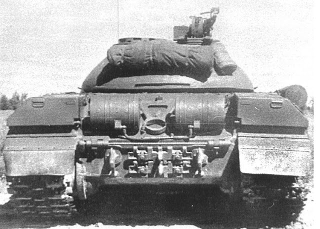
The T-10 was originally provided with a pair of BDSh-5 smoke bombs for generating a defensive smoke screen. The BDSh-5 was developed in 1944 for the T-34-85 and armoured fighting vehicles derived from the T-34. It continued to be used in a number of Soviet tanks until it was withdrawn from service in the 1950's due to the advent of self-generated smoke using the TDA smokescreen system. The BDSh-5 bomb measures 0.45 meters in diameter and 0.65 meters in length. Under conditions of minimal wind, a single BDSh bomb produces enough white smoke to cover an area of 40,000 square meters, or a square of 200 meters in width and length. The bomb burns and produces smoke for five to seven minutes. Smoke pours out of the circular opening on the surface of the cylindrical housing. The bomb is weighted so that the opening is always facing upwards even when floating in water, but it is not conducive for a T-10 to drop a BDSh-5 into water.


When the T-10M was introduced in 1957, it was also dependent on these smoke bombs as its only method of generating a smoke screeen. The photo below shows a pair of BDSh-5 smoke bombs on a T-10M.

In 1963, the TDA smokescreening system began to be included in new production T-10M tanks (T-10M obr. 1963) and were retrofitted into existing tanks, making BDSh-5 smoke bombs redundant. However, the mounting points and the quick-release mechanism for BDSh-5 smoke bombs were not removed so the option of using them remained after the modifications were made to accommodate fuel drums. The mounting points for smoke bombs are often seen coexisting with the mounting points for fuel drums on the same tank, but not all tanks had the fittings for external fuel drums whereas all have fittings for BDSh-5 smoke bombs.


Like the IS-3 and IS-7, the driver of the T-10 could be provided his own overhead hatch thanks to the geometry of the pike nose glacis design. The inclusion of a personal hatch for the driver is a basic ergonomic necessity of modern tanks that was unfortunately neglected in the IS-2, forcing the driver to ingress and egress the tank through the escape hatch in the belly, or the turret, which could only be done with reasonable speed if the turret was not pointed directly forward or elevated (the breech assembly is large and blocks the path of the driver). The IS-4 design included an overhead hatch for the driver, but it was only to permit the driver to drive with his head out of the hatch, thus eliminating the need for a vision port in the upper glacis as on the IS-2. This provided good driving visibility in non-combat conditions and improved the armour profile of the hull, but the hatch was too small for the driver to pass through. The IS-6 featured a driver's hatch as well, but it was designed as part of the upper glacis in the same configuration as the T-34 which was extremely unsatisfactory as the hatch was very heavy and the contortions required for the driver to pass through the hatch opening were simply not conducive to a quick escape.

Besides the structural issues of the belly design, the armour itself posed an issue, as a thickness of 16mm is noticeably less than the belly of the T-54 medium tank (20mm) and the M60A1 main battle tank (19mm), although is effectively the same thickness as the British Centurion medium tank, Conqueror heavy tank, and Chieftain main battle tank. American tanks like the M103 and M48 are in a class of their own in this category as they have double the thickness of belly armour with additional reinforcement on the very front end of the belly to increase the total thickness to 38mm. This, combined with the rounded shape of the hull belly, made these tanks unmatched in mine protection as the M48 proved in Vietnam.
The British heavy, medium and main battle tank were all designed under the same requirement of surviving a 20 lb anti-tank mine (usually represented by a Mk. 7 mine) underneath the track, and the Centurion tank is known to be incapable of surviving a partially-buried 20 lb mine detonated directly underneath the belly based on declassified reports. Compared to this, the T-10 belly only matches this protection level in the best case scenario, where the mine does not breach weld seams, but in the best case scenario, the resistance of the T-10 belly is significantly higher. It is worth noting that on these British tanks, the only design solution used to improve mine resistance was to slope the hull sides inward, thereby distancing the welded connection between the side and belly plates further from the track.
As a side note, the hull roof over the crew compartment had a thickness of 30mm, but the thickness of the various roof panels covering the engine compartment is only 16mm.
T-10, T-10A, T-10B TURRETS

A major impetus for the development of the Kirovets-1 that eventually led to the IS-3 was a tank vulnerability study commissioned by Gen. Nikolai Dukhov. The study found that the most common cause of serious heavy tank losses was hits to the turret, followed by hits to the front of the hull. This prompted the design of a turret with a radically new ballistic shape with a heavy emphasis on armour obliquity, as a result of which the level of armour protection was doubled over the IS-2 turret design. The T-10 turret represents another step forward from the IS-3 design with a more optimal ballistic shape and thicker armour. It is sometimes mistaken for the turret of the IS-3 from some perspectives, but the resemblance is purely superficial as the overall shapes and the curvature of the armour were completely different. However, just like the IS-3 turret, the length of the T-10 turret did not exceed the width of the hull, and because of this, the area of the front projection of the tank did not increase in size when the turret was turned to the side as the photo below (of a T-10M) shows, and therefore, the probability of being hit by incoming fire would not increase. Although this seems trivial, the considerable increase in the projected area of tanks with large turret bustles was a real disadvantage in a combat situation.

The T-10 turret is constructed from two pieces: the main structure is a large single-piece casting with a slightly curved cast plate welded on top to form a part of the turret roof. The turret weighs 6,500 kg in metal alone. MBL-1 grade steel was used for the turret. It is a softer steel compared to the 70L and 71L grades used for IS and T-34 turrets during WWII because the softer but tougher MBL-1 provided more protection against full-caliber armour-piercing shells. The drawing on the left below shows the turret of the basic T-10 and the drawing on the right below shows the turret of the T-10A. The T-10B shares the same turret with the T-10A. The T-10 and T-10A turrets share the same shape, same distribution of armour thickness and provide an almost identical level of protection.


The T-10 turret also abandoned the bolted access panel over the cannon breech assembly that could be found on the turret roof of the IS-3 and IS-4. This made the area much more resistant to direct hits and gave the turret greater structural rigidity with the minor downside that it was no longer possible to remove the cannon from its mount without lifting the turret off the hull. Instead of a bolted access panel, the same area on the T-10 turret roof was solid cast steel with a thickness of 40mm sloped at 85 degrees, and the welded turret roof plate at the rear half of the turret has a thickness of 30mm.
In December 1954, the roof of the turret was changed after tests were carried out earlier in the year. The triangular weld-on turret roof plate was replaced by an oval-shaped plate of the same thickness. This improved the overall structural strength of the roof against cannon fire. All T-10 turrets produced after December 1954 had this new turret design, and it carried over to the T-10A and T-10B turrets as well.
Both the T-10 and T-10A turrets share an almost identical oblong embrasure for the coaxial machine gun next to the embrasure for the main gun. The T-10 has the TSh2-27 sight with an articulating head portion so the embrasure in the turret for its aperture window is oblong in shape and quite small. The T-10A and T-10B with the TUP-21 backup sight is mounted directly onto the D-25TS cannon and lacks an articulated head and as such, a narrow but long vertical slit had to be cut into the turret instead.
On the whole, the T-10 turret is somewhat similar to the T-54 obr. 1949 turret in general shape, except with a more pronounced vertical curvature on all surfaces. From the side, the turret bears a strong resemblance to an egg halved along its longitudinal axis, but from the front and rear, the turret appears to be shaped like an isosceles trapezoid. The shot trap formed by the curvature of the IS-3 turret cheeks was also eliminated by the T-10 turret which had an almost completely convex design, lacking any surfaces from which an impacting shot could potentially ricochet into the turret ring or onto the hull roof. This was not an insignificant improvement considering that AP, HVAP and APDS rounds were still the primary anti-tank munitions carried by the tanks of the probable enemy at the time. The closest equivalent to this development is the progression of the Pz.V "Panther" gun mantlet design from the Ausf. A/D scheme to the Ausf. G scheme with the flattened lower edge.
According to Mikhail Kolomiets, the front of the turret had a thickness of 275mm to 250 mm, the sides were 157mm to 102 mm thick, and the rear had a thickness of around 90 mm. The front armour thickness figure refers to the thickness of the cheek from a side angle of 30 degrees, rather than from the direct front. As with practically all complex cast turrets, it is extremely difficult to find a reasonably accurate description of the distribution of thicknesses and angles of slope, and it is harder still to distill the true qualities of the armour in text. The biggest challenge lies in the sloping of the armour in two planes. This severely complicates calculations and introduces further variances in armour effectiveness depending on the angle of impact. Based on a review of all available sources, it appears that the most commonly reported thickness figure for the T-10 turret is 250mm, but the compound slope of 20-30 degrees at cheek region affects the protection value.

Besides the base armour thickenss of the turret front, it is necessary to also examine the gun mask that covers the embrasure for the main gun. The photo on the left below, by Pavel Lusta, shows the gun mask of an original T-10 while the drawing on the right below shows the gun mask of the T-10A and T-10B. The only real difference is that the former has an embrasure for the TSh2-27 sight whereas the former has an embrasure for the TUP-21 sight. Both gun masks are rounded in shape.


The gun mask is attached to the front part of the D-25TA and D-25TS gun breech assembly with large bolts and buffered with thick rubber bushings for shock absorption. The size of the embrasure in the turret is no wider than the gun breech assembly, and it is slightly shorter in height. The photos below show the small size of the embrasures in the turret for the coaxial machine gun and the TSh2-27 sight. The replacement of a traditional gun mantlet such as on the T-34, T-34-85, T-44, and IS-2 turrets with a narrow embrasure coupled with an armoured gun mask was a feature that the T-10 shared with postwar Soviet tanks like the IS-3, IS-4 and the T-54 obr. 1949 as this type of construction solved a plethora of structural issues, had a reduced likelihood of jamming from direct hits, and improved the protection of the turret as a whole.


The armour of the gun mask varies in thickness and overlaps with the turret base armour, but overall, the area covered by the gun mask reaches a similar level of protection as the turret cheeks from a frontal attack and does not exceed it because the base turret armour has two weakened zones. One of them is the edges of the embrasure which have a reduced armour thickness owing to the need to accommodate the trunnions for the gun cradle. The trunnion is marked (1) in the drawing on the left below. As the drawing on the right below shows, the gun mask overlaps with this area and more than doubles the total thickness. The armour thickness reaches its maximum at the base of the turret where the trunnion mounting pins are secured into the turret, marked (2). These pins run through the entire thickness of the turret, so they qualify as another weak point in the armour as a direct hit on the head on the pin might push it out and into the interior of the turret. Fortunately, they are extremely small relative to the overall size of the turret - the surface area of the pins occupy less than 0.5% of the total surface area of the front projection of the turret. The heads of these two pins can be seen from outside the tank if the gun mask is removed like in the photo on the right above.


The variable thickness of the gun mask reaches its maximum in the area directly in front of the gun breech assembly, as this part is otherwise unprotected by the turret armour. The thinner edges of the gun mask extend outward to cover the vertical slots cut into the turret for the coaxial machine gun and the coaxial telescopic sight. The maximum width of the gun mask is 835mm.
At the rear of the turret, there is small gap between the turret ring and the wall of the turret bustle. Unlike the M103 and Conqueror turrets which had a large shot trap built into their turret bustles, this gap in the bustle of the T-10 turret is simply a zone of greatly reduced armour thickness. The thickness of the thin floor plate joining the turret ring to the walls of the turret bustle in this gap is not known, but based on the drawing below, it appears to be half the thickness of the hull roof (40mm), so it should be around 20mm. To reduce the vulnerability of this zone, an additional curved armoured rib welded to the underside of the floor plate to act as a spaced armour screen beginning with the T-10A turret. The ideal design would omit gaps and shot traps like the turret of the IS-3, but in this case, the height of the gap is small enough that it is an extremely minor chink in the turret armour.
Given that the sides of the turret appear to be set at the same angle as the upper side hull plates (47 degrees), the armour at the widest point - next to the commander's station and loader's station - should be set at this angle.
The turret ring race ring is recessed below the surface of the hull roof and there is a set of interleaved rings to seal the gap from bullet splash. To further reduce the probability of a jammed turret, the hull armour plates on the front and sides have a lip with a height of around 27-35mm that covers the small gap between the base of the turret and the surface of the hull roof. It's rather unlikely that this lip is enough to stop a cannon shell, but it is more than enough to reliably keep out heavy machine gun bullets and shell splinters and it may also be enough to resist direct hits from a 20mm autocannon.

These details are represented in the drawing below.
The interleaved rings around the circumference of the turret ring are clearly shown in the drawing below.

T-10M TURRET

To help control the weight gain from the new features added in the Chelyabinsk T-10M (Object 734) without significantly compromising the protection level of the tank, the thickness of the welded turret roof was reduced from 30mm to 20mm. However, the Leningrad T-10M (Object 272) retained a welded turret roof with a 30mm thickness, and the constructional turret roof had its thickness increased from 40mm to 50mm without changing the angle of slope of 85 degrees. Given that the Object 272 became the standard T-10M design for serial manufacture in both ChTZ and LKZ since 1962, it can be considered the de facto model.


Although there were some changes in the shape of the front of the turret, the basic design was more or less unchanged. At the front of the turret next to the gun barrel, the base of the turret has a thickness of 250mm. Physically, this is the thickest section of armour found on the entire turret, but it is completely flat in the horizontal plane. As the turret curves upward to form the roof over the gun breech, the thickness is reduced to 200mm with a vertical slope of 24 degrees, and then transitioning to 135mm with a slope of 49 degrees. Based on these simple figures alone, it appears that the line-of-sight (LOS) armour thickness reduces along the height of the turret, but this is only because the horizontal slope of the turret is completely ignored.

Like the T-10 and T-10A turrets, the edges of the embrasure in the T-10M turret also had a reduced thickness to accommodate the trunnions, marked (2) in the drawing below. The trunnions and the trunnion mount was of a different, more robust design, but the modified trunnions were still secured to the turret using pins, marked (1) in the drawing below.

The trunnion was moved forward relative to the trunnion mounting pins to reflect the different center of gravity of the M62-T2 cannon. Indeed, the entire cannon breech assembly was mounted slightly further forward in the turret, but the thickness of the armoured gun mask was not increased. On the contrary, the overall thickness of the gun mask was significantly reduced to only around 100mm and the amount of protection that it offered was considerably lower. However, the diameter of the M62-T2 gun tube was larger without a corresponding increase in the size of the embrasure, so proportionately speaking, this part of the gun mask of the T-10M covered a slightly smaller surface area and constituted a smaller weakened zone.


Like the gun masks of previous T-10 models, the gun mask on the T-10M turret was attached to the end of the M62-T2 gun by four large bolts, and like the earlier gun mask designs, the T-10M gun mask has a maximum width of 835m, but the shape of the gun mask was changed. Now, it is no longer rounded but was instead semi-cylindrical as the photo below shows.

The lowest edge of the gun mask is flat in the vertical plane but retains the same 24 degrees of horizontal slope.


The two photos below show the T-10 turret with the gun mask removed. The photo on the right below (from Carrey on Primeportal.net) gives a closer view of the four large bolt holes which are used to mount the gun mask onto the M62-T2 gun.


The photo below (from Mikhail Baryatinsky) shows two T-10M tanks being prepared for scrapping. The size of the embrasure for the main gun can be clearly seen.

The thickness of the T-10M turret next to trunnion mounting pins is 250mm. This zone is the only part of the turret that could be considered close to flat as there is only 16 degrees of horizontal slope with no vertical slope. Overall, the level of protection offered by the T-10M turret is equivalent to the T-10 turrets produced from 1955 to 1956 and onwards.
The rear of the turret also remained at the same level of protection. The base of the bustle had an armour thickness of 102mm at a flat angle, thinning down to 68mm at an angle of 54 degrees. Combined with the curvature of the turret in the horizontal plane, the armour above the 102mm belt at the base of the bustle is theoretically enough to withstand full-caliber armour-piercing shells from a 57mm high velocity cannon from any range.
The gap at the base of the turret bustle remained, but the bustle floor plate joining the turret ring to the walls of the turret bustle changed in design. The floor plate in the T-10M turret extends away from the turret ring before sloping upwards to join with the walls of the turret bustle, thus creating additional internal space without adding weight. The curved armour rib welded to the underside of the floor plate was removed, but the level of protection did not change because of the slope of the floor plate. The reason for this change was to accommodate the new ammunition stowage scheme.

PROTECTION AGAINST HEAT
The protection of the hull sides against shaped charges was considered insufficient as the frontal arc of immunity against contemporary HEAT weapons was too narrow. For the PG-2 grenade with an 82mm warhead fired from the RPG-2 (rated penetration of 180mm RHA), the maximum angle of attack where the armour remained immune was just ±26 degrees, meaning that a PG-2 grenade would only fail to perforate the armour when the angle of impact is 26 degrees off from the perpendicular axis in either direction. For the PG-82 grenade with an 82mm warhead fired from the SPG-82 (rated penetration of 175 mm RHA), the maximum angle of attack was ±27 degrees. For the VBK-881 grenade with an 82mm warhead fired from the B-10 recoilless gun (rated penetration of 250mm RHA), the maximum angle of attack was ±22 degrees. For the VBK-883 grenade with a 107mm warhead fired from the B-11 recoilless gun (rated penetration of 290mm RHA), the maximum angle of attack was ±20 degrees.
For a 76.2mm HEAT shell of unknown type, presumably the BK-354M round for the D-56T gun of the PT-76, the maximum side angle was ±21 degrees. For an 85mm HEAT shell of unknown type, presumably the 3BK-7М round for the D-48 and D-70 anti-tank guns, the maximum side angle was ±15 degrees. However, keep in mind that all of these figures are only for the lower side hull armour which is a flat 80mm plate. As usual, the Soviet criteria for tank protection was extremely strict and only the least protected portion of the side hull projection was considered. If a less pessimistic perspective were adopted instead, it is obvious that the upper side hull armour of 170mm to 176mm would have a decent chance of resisting a shot from an RPG-2 or an SPG-82 at a flat angle. Even against the 85mm HEAT round which had the most potent warhead of all the types tested, the maximum side angle of immunity for the upper hull sides would be around ±56 degrees, so the frontal arc of immunity would be 112 degrees.
The M371A1 HEAT round fired from the 90mm M67 recoilless rifle penetrated 250mm of armour plate, and the warhead of the M72 LAW (from original up to the A3 model) penetrated 200mm of armour. The original M28 HEAT rocket for the M20 Super Bazooka penetrated 265mm of armour and the newer M35 rocket penetrated 280mm of armour. It is worth noting that the penetration power of all of these weapons deteriorated somewhat on sloped plate due to fuzing issues. These weapons were enough for the frontal armour of a T-34 or even a T-54, but generally speaking, man-portable recoilless rifles and rocket launchers lacked sufficient penetration power to defeat the armour of the T-10 from the front unless the lower glacis armour was hit. The turret could be defeated more easily than the upper glacis, but the rather low overmatch would only result in minor internal damage. Nevertheless, the T-10 was clearly not immune to such weapons, and that fact alone is worrying.
Larger crew-served weapons like the 106mm M40 recoilless rifle were capable of handily defeating the armour of the T-10 from the front. The M344 HEAT shell penetrates 433mm RHA which gives it an overmatch factor of 100mm against the upper glacis armour, making it an effective countermeasure against the T-10. Nevertheless, the T-10 was still noticeably better protected in this regard compared to its direct counterparts the American M103 and the British FV214 Conqueror. The upper and lower glacis armour of both of these tanks could be pierced by the PG-7V round fired from an RPG-7 which had 260mm of penetration with the basic PG-7 grenade, and the BK-833 round fired from the crew-served 107mm B-11 recoilless gun had 381mm of penetration which is more than enough to pierce the hull armour of both tanks at any location.
Based on a simple comparison of the LOS thickness of armour and the penetration power, the upper glacis of the T-10 is ostensibly incapable of resisting the 90mm M431 HEAT shell fired from the M36 and M41 guns of the M47 Patton and M48 Patton respectively, and it appears to be completely insufficient against the 105mm HEAT rounds of the L7 such as the M456. However, there are serious caveats - during ballistic tests conducted in Yugoslavia, it was found that 90mm M431 HEAT shells (with the M509A1 fuze) failed to fuze on the upper glacis armour of a T-54A if the tank hull was angled 20 degrees sideways. The resulting compound angle is only 62 degrees but this was apparently sufficient to cause a fuzing failure. It can be expected that the 105mm M456 would perform just as poorly as it uses the same M509 fuze as the M431.
Because additional angling was required to achieve this effect, this would only count as circumstantial protection for the T-54, but for the T-10 which has a structural 40 degrees of horizontal slope on its upper glacis, a 90mm or 105mm HEAT shell would need to impact the upper glacis from a side angle of at least 36 degrees in order to simply fuze properly, and conversely, the upper glacis of the T-10 would be capable resisting these shells in a 70-degree frontal arc with the same consistency displayed in the Yugo trials. As such, HEAT ammunition for M47, M48 and M60A1 tanks cannot be considered reliable countermeasures against the T-10 hull. The issue with fuzing on highly oblique targets was only remedied in the early to mid 1980's with the M456A2 and 105mm DM12 HEAT rounds. However, the turret of the T-10 would be more vulnerable, especially at its gun mask area. Only the edges of the turret would have a sufficient line of sight thickness to resist HEAT shells as well as a sufficiently steep angle of obliquity to cause fuzing issues.
The Yugoslavian test results were not a isolated cases. During the Korean War, it was found that M6 Bazookas and M20 recoilless rifles were ineffective against North Korean T-34 tanks despite having a nominally sufficient penetration power to go through the thickest parts of the tank. The issue was that the all-aspect sloping of the hull of the T-34 resulted in frequent fuzing failures, so the warheads simply failed to detonate or they detonated with a significant delay, causing the shaped charge to impact the armour from a very short standoff distance. Broadly speaking, fuzing issues were likely to occur if the angle of impact exceeded 60 degrees.
The issues with fuzes during the early years of the Cold War were noted by both sides and sometimes led to interesting creations. Indeed, the well-rounded hull of the famous Object 279 depended on the low fuzing reliability of HEAT shells as the primary defense mechanism. By having additional angled inserts added on top of the cast steel hull to increase the relative slope of the armour, Soviet engineers were able to greatly reduce the vulnerability of the tank to HEAT shells without raising its weight to an impractical level. These inserts were rather lightweight so they were not sturdy enough to act as armour against solid shot AP or APDS projectiles, but were just thick enough to ensure that the fuzes of HEAT shells could not pierce the skin and would instead be deflected and destroyed, thus causing the shell to fail to initiate on impact.
Graze-sensitive fuzes for anti-tank missiles would not suffer from the same issues. Such devices began appearing in the early 1970's and would have been an effective means of defeating the T-10M as it was still in service and would likely have routinely faced NATO anti-tank missile platforms owing to its high priority as a heavy tank. Furthermore, the M456A2 and its West German licence-produced clone the DM12 were no longer susceptible to fuzing issues on highly oblique targets as a new fuze, known as the full-frontal area impact switch (FFAIS), was installed.
PROTECTION AGAINST HESH
The high obliquity of the upper glacis armour may also useful against HESH or HEP rounds in certain circumstances as it is high enough to be more useful than harmful, but still, the thickness of the armour is insufficient against HESH rounds larger than 90mm in caliber. Moreover, the high obliquity of the T-10 armour may be rather useless if it is attacked from a very long range as the arcing trajectory of HESH rounds - which are slow by nature - will tend to impact at a diving angle.
In a Soviet document titled "Воздействие 106-мм Бронебойно-Фугасных Снарядов Безоткатного Орудия На Монолитную Стальную Броню", it is reported that the M346 projectile, which has a diameter of 105mm and contains 3.25 kg of Composition A3 but lacks an inert nose cap, is capable of defeating a 120mm plate at 65 degrees. Cannon-fired 105mm HESH rounds should achieve the same result. Needless to say, 120mm HESH is easily capable of defeating a 120mm plate as the graph below shows.

However, it must be understood that HESH rounds were not necessarily an effective counter to T-10 tanks as the effectiveness of any given type of ammunition does not hinge entirely on the ability to defeat the armour of the target. It is certainly an integral component of the equation, but it is not the only factor. For HESH rounds, the primary factor that hinders its ability to serve as an effective weapon against T-10 tanks is their poor ballistic performance. Due to the plethora of technical constraints associated with the proper function of squash head warheads, HESH shells must be launched at a low muzzle velocity of around 600 m/s, not more. Combined with the poor aerodynamic form of the HESH projectile, which is another technical constraint related to the squash head design, the ballistic trajectory of HESH shells is extremely pronounced and the shell is extremely sensitive to deflection by crosswinds despite their characteristically high mass.
As the graph on the left below shows, a HESH (HEP) shell takes a significantly longer time to reach the target compared to four other types of armour-piercing ammunition and has an extremely arced ballistic trajectory. The long flight time makes it much more difficult to hit a moving target. The graph on the right below shows the effect of a 10 m/s crosswind on the deflection of three types of armour-piercing ammunition. APDS rounds are the least affected, making them much easier to use, especially for early Cold War tanks that lack a crosswind sensor, whereas HESH rounds are severely affected by crosswinds.


Even with a suite of sensors and a ballistic computer that can handle a variety of environmental factors, modern tanks firing HESH shells still have a notably worse probability of hit on tank targets, especially moving targets. Needless to say, tanks such as the M60A1 will find it extremely difficult to use HESH rounds against moving T-10 tanks at long range, whereas most T-10 models that an M60A1 would encounter will tend to have a stabilized gun that can deliver effective return fire, and although Chieftains have a stabilizer, there is no reason for them to use HESH rounds when they have L15 APDS rounds that facilitate a higher probability of hit and have sufficient penetration power to defeat the frontal armour of any T-10.
FIREFIGHTING
The PPO firefighting system came standard on the T-10. This was an automated system that was controlled by the driver with two modes of operation: the 'automatic' mode, or the 'semi-automatic' mode. Three carbon dioxide fire extinguisher bottles were provided and each would be expended in a single powerful burst with each activation. The fire extinguisher bottles were placed behind and to the right of the driver's seat.
In the 'automatic' mode, the system alerts the driver of the source of the fire, shuts off the engine, and cuts off the engine air intake. Then, one of the three fire extinguisher bottles are activated and the entire compartment is flooded with the extinguishing agent. In the 'semi-automatic' mode, the system alerts the driver of the presence of a fire via an audio alarm and a signal light, but takes no action on its own. The driver can then choose whatever action he deems most suitable at the moment. He can control the system from his station and choose to activate any number of bottles.
Six TD-1 temperature sensors were placed in strategic locations around the engine compartment and oriented at the most probable source of potential fires. The system reacts to a rise in temperature to 180 degrees Celsius and has a response time of 10 seconds. The long response time is due to the inherent limitations of the use of thermocouples as temperature sensors. Naturally, the oxygen content in the engine compartment is quite low due to the high concentration of carbon monoxide and fumes so fires tend to be easier to extinguish as they are already facing partial oxygen deprivation, but fires cannot be detected instantly due to the limitations of the sensors and the lack of any other feedback system to alert the crew, so the fire has more time to spread and this makes it much more difficult to extinguish.
Because the PPO system only protects the engine compartment, fires in the fighting compartment must be handled manually by the crew using two carbon dioxide OU-2 hand-held fire extinguishers to extinguish fires. The fire extinguishers are placed on the front right corner of the fighting compartment and are most easily reached by the driver, but the loader is able to access them as well. Carbon dioxide is suitable against Class B and C fires, namely fuel and electrical fires, which are the predominant causes of fire in a tank. Although it is not as poisonous as carbon monoxide, carbon dioxide can cause asphyxiation by hypoxia and it is is toxic in high concentrations, so it is unsafe to remain inside the tank after the extinguisher bottles have been discharged.
In 1964, the "Rosa-2" firefighting system was installed on new T-10M tanks and it began to be retrofitted to older tanks. Like the older system it replaced, "Rosa-2" only covers the engine compartment. The main improvements of "Rosa-2" was in the speed and reliability of extinguishing fires compared to the PPO system. This was achieved by using a halocarbon fire extinguishing agent designated "3.5"; a pressurized combination of ethyl bromide and carbon dioxide. The mixture is very effective at retarding flames, but also highly poisonous and carcinogenic. Three extinguisher bottles were provided, giving the driver three attempts to fight the fire in the engine compartment.
SMOKESCREENING SYSTEM

The T-10 was originally provided with a pair of BDSh-5 smoke bombs for generating a defensive smoke screen. The BDSh-5 was developed in 1944 for the T-34-85 and armoured fighting vehicles derived from the T-34. It continued to be used in a number of Soviet tanks until it was withdrawn from service in the 1950's due to the advent of self-generated smoke using the TDA smokescreen system. The BDSh-5 bomb measures 0.45 meters in diameter and 0.65 meters in length. Under conditions of minimal wind, a single BDSh bomb produces enough white smoke to cover an area of 40,000 square meters, or a square of 200 meters in width and length. The bomb burns and produces smoke for five to seven minutes. Smoke pours out of the circular opening on the surface of the cylindrical housing. The bomb is weighted so that the opening is always facing upwards even when floating in water, but it is not conducive for a T-10 to drop a BDSh-5 into water.


When the T-10M was introduced in 1957, it was also dependent on these smoke bombs as its only method of generating a smoke screeen. The photo below shows a pair of BDSh-5 smoke bombs on a T-10M.

In 1963, the TDA smokescreening system began to be included in new production T-10M tanks (T-10M obr. 1963) and were retrofitted into existing tanks, making BDSh-5 smoke bombs redundant. However, the mounting points and the quick-release mechanism for BDSh-5 smoke bombs were not removed so the option of using them remained after the modifications were made to accommodate fuel drums. The mounting points for smoke bombs are often seen coexisting with the mounting points for fuel drums on the same tank, but not all tanks had the fittings for external fuel drums whereas all have fittings for BDSh-5 smoke bombs.

DRIVER'S STATION


Like the IS-3 and IS-7, the driver of the T-10 could be provided his own overhead hatch thanks to the geometry of the pike nose glacis design. The inclusion of a personal hatch for the driver is a basic ergonomic necessity of modern tanks that was unfortunately neglected in the IS-2, forcing the driver to ingress and egress the tank through the escape hatch in the belly, or the turret, which could only be done with reasonable speed if the turret was not pointed directly forward or elevated (the breech assembly is large and blocks the path of the driver). The IS-4 design included an overhead hatch for the driver, but it was only to permit the driver to drive with his head out of the hatch, thus eliminating the need for a vision port in the upper glacis as on the IS-2. This provided good driving visibility in non-combat conditions and improved the armour profile of the hull, but the hatch was too small for the driver to pass through. The IS-6 featured a driver's hatch as well, but it was designed as part of the upper glacis in the same configuration as the T-34 which was extremely unsatisfactory as the hatch was very heavy and the contortions required for the driver to pass through the hatch opening were simply not conducive to a quick escape.

That said, the heavy tank models with a pike nose glacis were not without flaw. The driver's hatch on the IS-3 could not be opened from the outside because the rotatable MK-4 periscope embedded in the hatch was too tall and prevented the hatch from being swung off to the side. To open the hatch, the driver had to pull out the periscope from inside and stow it away before lifting the hatch and swinging it off to the side. This delays a quick escape if the tank were knocked out. Because of this limitation, the driver would be able to enter and exit through his hatch at will but he would first need to enter his station through the turret. Other tanks with rotatable periscopes in the driver's hatch used a split-hatch design to overcome this issue.
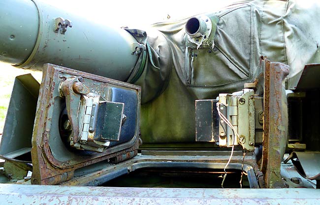
To remedy the drawbacks of the IS-3 design, the T-10 uses the same periscope layout as the IS-7 with a more streamlined, low profile TPV-51 prismatic periscope embedded in the driver's hatch that did not need to be removed before opening the hatch. Two TPB-51 prismatic periscopes supplement the forward-facing TPV-51.

The TPV-51 could be replaced without the driver leaving the tank by simply pulling the periscope out of its socket in the periscope housing and installing a new one in its place. Visibility from the TPV-51 was much better than the single MK-4S periscope of the IS-3, especially in the horizontal plane. The MK-4S could be rotated, so in theory, the driver of an IS-3 could see everything in front of the tank and beside it, but in practice, the driver needed both hands to use the steering tillers and the gearshift when the vehicle was in motion, so the supposed advantages of this setup do not offset the narrowness of the periscope. For comparison, the width of the TPV-51 periscope is 208mm whereas the width of the MK-4S is only 91mm.

The two TPB-51 prismatic periscopes are embedded in the top edges of the two "pike" surfaces of the upper glacis and are aimed at the 10 o'clock and 2 o'clock positions. The TPB-51 periscopes are identical to a TPV-51 in all dimensions except that they are square and not rectangular, which is somewhat unusual. It is likely that such periscopes were used so that the size of the holes in the frontal armour plates were minimized to reduce the reduction in structural integrity and the uniformity of armour thickness. The IS-7 uses an identical periscope layout but has TPV-51 periscopes instead of the square TPB-51.


If damaged, each TPB-51 periscope can be replaced from inside the tank by unbolting it from its frame and then simply inserting a new one into the empty slot. The same is done to replace the TPV-51 periscope in the hatch. A set of two spare TPB-51 periscopes and one spare TPV-51 are carried in the T-10 in aluminium boxes. A dome light is installed on the hull ceiling to the left of the driver's seat. There is a fuze box for the tank's electrical system on the left wall of the driver's station.
Some accessories were provided for the driver to improve his driving experience. A spring-loaded helical brush could be affixed to the TPV-51 periscope. The helical brush is powered by a small electric motor and continually sweeps up and down the aperture window to clean it from mud, snow or rain. This video of an Object 268 review shows the installation of the brush being demonstrated briefly.


The combination of three fixed periscopes providing coverage for the forward arc of the tank grants the driver an acceptable level of visibility, although it is worth pointing out that the layout of the driver's periscopes is imperfect. Instead of having two square prismatic periscopes embedded in the upper glacis armour, rectangular periscopes could have been installed in the hatch over the driver's station much like the periscope layout of the M1 Abrams. This would have conceivably provided much better visibility for the driver without any noticeable loss in protection. Nevertheless, the driver has an acceptable level of visibility. As the drawing on the right below shows, the size of the driver's hatch is quite average and it has a bulge behind the TPV-51 periscope to better accommodate the driver's head.
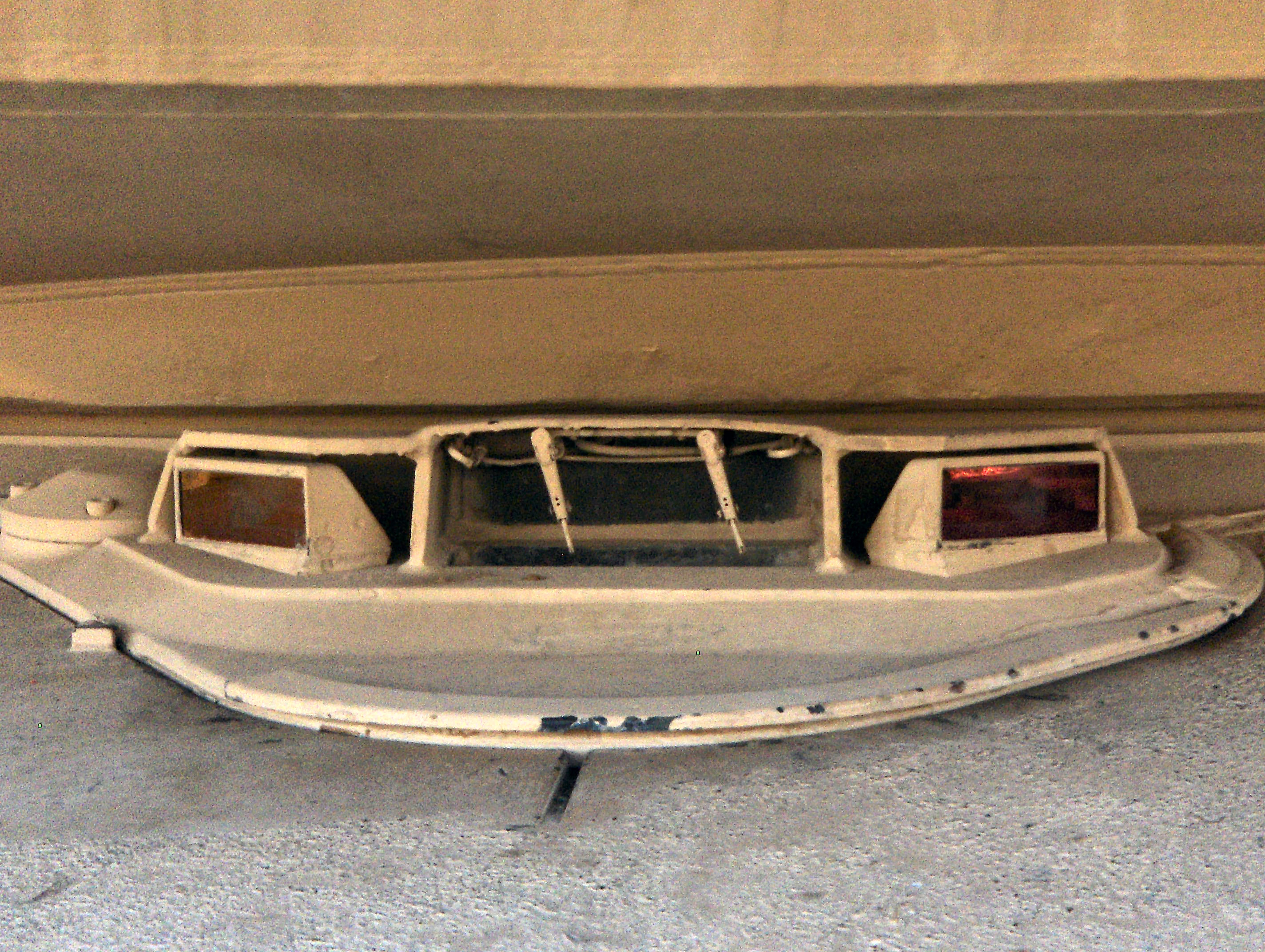
Additionally, an important design feature of the T-10 driver's hatch, inherited from the IS-7 and absent on the IS-3, was the high-strength locking mechanism used to secure the hatch. This was a necessary measure because of the very heavy shock loads that the tank was expected to survive, as it was meant to be protected from 100mm and 122mm shells. The highly reinforced nature of the locking mechanism may also be beneficial against blast and direct hits, which would be an important consideration for the T-10 because the roof and hatch are exposed from ground level and stood a moderately high chance of being struck directly by incoming shells. Rather than a conventional tension lock or a latch, the hatch is locked by a camming mechanism, whereby the hatch is cammed forward and slotted into a groove within the rim of the hatch opening on the roof plate. This means that the plate is not only structurally secured from being pushed inward, like any conventional driver's hatch, but also more secure from popping out.


Then, to lift the hatch, the driver lifts the opening lever from the locked position (completely vertical) until it is in the opening position (completely horizontal), and in doing so, the lever cams the hatch slightly rearward before it begins to lift it, thus allowing the rim to disengage from the groove in the hull roof plate. To swing the hatch over to the right, the driver pushes against the opening lever until it reaches a stopper, and he then lowers the lever to the locked position. The swinging of the hatch is assisted by a spring, housed in a tube next to the hatch opening mechanism and connected to the hatch hinge pin by a lever arm, as shown in the image on the right above. The spring is marked (21) and the lever arm is (19). It was necessary to include a spring assist mechanism because the hatch is very heavy, which can make it very difficult to open if the tank is banking to the left, so that the driver would have to fight against gravity to swing open the hatch. The spring assist was also borrowed from the IS-7 driver's hatch design. The process is reversed for closing the hatch and locking it in place.
Due to the central location of the driver's station, it is not possible for the driver to pass through the hatch opening unless the turret is shifted to one side or the gun is elevated and the same limitations apply when he is driving with his head out of the hatch.


When driving "unbuttoned" with the turret in the travel position (aimed in the 6 o'clock direction and gun fixed to the travel lock), a curved water deflector attached to the turret bustle prevents rain water from flowing down the surface of the turret bustle and directly into the driver's neck, as shown in the photo below. The driver's hatch itself had a sponge rubber seal along its perimeter that provided a good water seal. This was replaced with a rubber O-ring seal in the T-10M to provide a more reliable hermetic seal.

The driver's seat is mounted directly on the floor of the hull between the torsion bar housings of the second pair of roadwheels. The gap between the torsion bar housings is 326mm in width, implying that the seat has the same width. It was necessary to install the seat on the floor of the hull and not on top of the torsion bar housings in order to provide the driver with the maximum amount of headroom. The width of the driver's station from shoulder-to-shoulder is 678mm.
As usual for Soviet tanks, the backrest of the driver's seat is adjustable in inclination with a choice of four positions and it is possible to place the backrest into a reclined position , making it a convenient and convenient place for the driver to sleep. The seat can also be folded forward which is useful when exiting the tank through the hull escape hatch. When the tank is driven with an open hatch, the driver's seat is not only raised but pivoted forward by the raising mechanism. This is because the driver's seat is not directly underneath the hatch but is actually slightly behind it, as mentioned earlier in the "Protection" section of this article.

To the driver's left, four accumulator batteries are installed on a special rack, and placed to the driver's right is ammunition racks for the 122mm cannon and three fire extinguisher bottles for the automatic firefighting system. The two 5-liter compressed air tanks for the pneumatic engine starting system are mounted to the lower glacis, behind and slightly above the driver's control pedals. These are standard air tanks with an operating pressure of 150 kg/sq.cm.
As usual, the driver steers the tank with steering tillers. These are placed on either side of the driver's legs and the driver's dashboard is located directly in front of him. The screenshot below (taken from part 2 of Inside the Chieftain's Hatch: Object 268) shows the dashboard from an Object 268 which does not differ from the T-10. The tachometer gauge is helpfully placed centrally on the dashboard. Strangely enough, there are two warning lights on the edges of the dashboard marked "Out of clearance".

The push-pull control rods for the various control pedals and levers - e.g. brakes, clutch, gear shift, accelerator, etc - run all the way to the engine compartment on top of the torsion bar housings.
There are a total of three headlights arranged on the upper glacis, two on the right and one on the left, together with an S-58 electric buzzer (horn) on the left side of the upper glacis. The horn is activated by a button located to the right of the driver's instrument panel. Depending on the model of T-10 and the circumstances, the headlights may have IR lamps (FG-100), full white light lamps (FG-10) or blackout lamps (FG-26, FG-102). A variety of combinations of these headlights can be seen in photographs of various T-10 tanks over the years of its career in the Soviet Army, with no discernible pattern.
All of these devices are protected by a guard cage. The photo below from from Dave Haskell shows the headlight on the left of the upper glacis.

The T-10A had the TVN-1 infrared driving periscope as part of its standard equipment in 1956. The tank lacked any other night vision equipment besides this periscope so there was practically no possibility of fighting without additional white light illumination, but having the TVN-1 gave heavy tank units equipped with the T-10 a basic ability to maneuver in complete darkness during nighttime. Most importantly, large columns of tanks on a march would no longer be visible from the air. The periscope had a 1x magnification and a field of view of 30 degrees. The driver views the image through a viewing prism.


The infrared light source for the periscope is a single FG-10 infrared headlight installed on the right upper glacis plate. The 40 W infrared lamp of the FG-10 provided limited illumination, giving the driver a limited viewing distance of only 30 to 35 meters and curbing the average speed of the tank to only around 15 km/h on a dirt road. It was also challenging for the driver to negotiate obstacles and cross narrow paths. Combat maneuvering would be impossible or at least highly dangerous, so the tank is limited to firing from static positions or from a slow crawl, with the commander giving directions to the driver. The TVN-1 had a very constricted objective lens and provided a limited field of view, as the photos below show. There was a large deadzone in front of the tank due to the limited visibility, so the driver needed to be exceptionally careful when overcoming obstacles and crossing trenches. The TVN-1 lacked a heating system, so fogging could be an issue.


The T-54 was the first to receive the TVN-1 as the T-54 obr. 1954 variant. The main hurdle in implementing the TVN-1 on the T-10 was compatibility issues.
The T-10M received the TVN-2T infrared periscope together with a new FG-100 infrared headlight. The FG-100 still had a 40 W lamp and was interchangeable with the FG-10 in practice, but the new periscope granted an increased viewing distance of 60 meters which made it much easier for the driver to navigate and enabled the tank to be driven at a much higher average speed of up to 25 km/h on dirt roads. The periscope had 1x magnification and a field of view of 30 degrees. One advantage of the TVN-2T over the TVN-1 is that the new design is binocular and therefore gave the driver a modicum of stereoscopic vision. The most apparent downside to the TVN-2T is that because the image is displayed on two eyepieces, the driver must have his face pressed up against the brow pad of the periscope to have the proper eye relief. Due to the layout of the driver's station, the driver would have to lean quite far forward to do this, and it is not a comfortable position for long durations. Another downside is that the periscope still lacked a heating system.
The TVN-1 or TVN-2T periscope would be installed in the hatch periscope housing next to the slot for the TPV-51 periscope. In order to fit the night vision periscope, new hatches with the appropriate periscope slots had to be installed in lieu of the original T-10 driver's hatch. The TVN-1 could not be installed in a hatch designed for the TVN-2T and vice versa. For both systems, the TPV-51 had to be pulled out of its slot to have armoured plug is inserted in its window to provide protection from bullets as well as to act as a barrier against water, mud and other unwanted foreign objects. Only then could the night vision periscope be installed. All of this could be done without leaving the tank, but this would only be done in a non-combat situation for obvious reasons. The drawing on the left below shows the TVN-1 as it appears when mounted in its slot, and the drawing on the right below shows the TVN-2T in its modified slot. Note the difference in the sealing mechanism for the periscope slot cover - it is absent for the TVN-2T slot.


Due to the restriction to a single narrow forward-facing vision device, the driver must take much greater caution when maneuvering the tank and the speed of the tank must be limited for safety reasons. The limited visibility range also forces the commander to determine a suitable route using his more powerful TKN-1 night vision device to direct the driver. During combat, the driver would most likely be forced to travel in straight lines and he will find it difficult to maneuver the tank into advantageous positions, such as by finding cover, driving over smoother paths to improve the accuracy of fire for the gunner. It would also be very difficult for him to detect and avoid tank traps.
On tanks that were equipped with the TVN-1 or the TVN-2T, the periscope could be installed in a special mount with the hatch opened. On the T-10A and T-10B, the TVN-1 would be installed on a special bracket that was clamped to the edge of the hatch opening, and on the T-10M, a simplified quick-detachable mounting system with a dovetail rail was provided on the hull roof in front of the driver's hatch. This feature improved the speed of nighttime maneuvers in non-combat conditions by allowing the driver to navigate with the benefit of having his head out of the hatch and access to a night vision device at the same time. It is also much more comfortable for the driver as he would not need to lean forward to use the periscope in this situation.


The night vision periscope is quite tall when configured for open-hatch driving and will obstruct the main gun, but this is irrelevant as turret rotation is automatically locked if the driver's hatch is opened. The safety rules for driving with the night vision periscope from an open hatch were the same as in daytime.

When not in use, the night vision periscope would be stowed inside the tank in a box attached to the wall of the upper glacis.
When it was introduced, the TVN-2T was fitted to Soviet tanks on a wide scale. The IS-2M, IS-3M and IS-4M were all upgraded with the TVN-2T to bring their night maneuvering capabilities to a modern level, and of course, the standardization of all night vision equipment into a single set running on a standard 27 V power supply was very sensible from a logistics perspective.
The GPK-48 gryocompass was installed in the T-10 together with the TVN-1 in 1956. It was placed in front of the gear selector lever, to the right of the accelerator pedal. The use of a gyrocompass together with a map gives the crew a rudimentary form of an Inertial Navigation System (INS). It is most useful when it is not possible to navigate by landmarks, such as when crossing rivers by snorkeling or when driving at night. To use it, the driver aims the tank in a specific direction and turns on the gyrocompass to set a reference point. For example, if the tank needs to travel in a perfectly straight line, the driver must steer the tank so that the bearing indicator line remains at the '0' point.


A circular escape hatch is installed in the belly of the tank, located behind the driver's seat. It is placed between the torsion bar housings for the second and third roadwheels. Having a diameter of 495mm, the size of the escape hatch is comparable to the commander's cupola hatch and it should certainly be more than enough to facilitate a speedy exit if the situation calls for it. A central post protrudes 84mm above the hatch.

The escape hatch designs is of the drop-out type. The hatch is secured to the hull belly by two locking lugs at the edges of the hatch which are spring-loaded and by two locking levers which are mounted to the central post. A cable runs between the two locking lugs. When pulled sharply upwards, the cable draws the two locking lugs back into their recesses and this releases the hatch, allowing it to drop free from the hull belly. To reinstall the hatch, someone inside the tank simply pulls it back up through the hatch opening. The beveled surfaces of the locking lugs slide against the edge of the hatch opening to push the lugs inward, and the lugs spring out to lock the hatch in place once they have cleared the edge of the hatch opening.


From an automotive standpoint, T-10 shared only a few similarities with previous heavy tanks like the IS-4. The suspension was derived from the IS-4, but the T-10 used the V12-5 engine instead of the V-12, the transmission was different, and the cooling system was absolutely unique, having only been implemented on prototypes like the IS-7 in the past.
Fixed aluminium side skirts were attached to the sponson stowage bins along the entire length of the sides of the hull. These are partial skirts as they only cover the returning track and the tops of the return rollers unlike the full skirts of a Centurion which cover the entire height of the hull. The main purpose of most side skirt designs is to reduce the amount of dust or sand kicked up by the tracks as it can form large clouds that may betray the location of moving tank units to enemy observers, but the effectiveness of the partial skirts in this capacity is probably not as high as full side skirts and the partial skirts are also too narrow to cover much of the crew compartment, so it isn't likely that they will have the chance to fulfill a secondary role as spaced armour screens. Aluminium side skirts were later fitted to the IS-3 and IS-4 as part of the IS-3M and IS-4M modernizations.
Aluminium mud guards with rubber flaps were fitted over the idler wheels. Beginning with the T-10M, rubber mudflaps were fitted to the nose of the glacis next to the mud guards as shown in the photo below from Dave Haskell.

A V-shaped splash guard is fitted halfway up the upper glacis, above the towing hooks to prevent water from flowing up the glacis and splashing the driver through his open hatch when the tank is fording a shallow stream.
As usual, the T-10 came with an unditching log for self-recovery if the crew found themselves stuck and there was not enough traction to escape. Due to the large number of equipment carried on the back of the hull, the unditching log was strapped to the right side of the hull instead of the normal position, behind the drive sprockets.

The T-10 was driven by the V-12 series of twelve-cylinder supercharged diesel engines with a displacement of 38.88 liters. The engine has roots in the original V-2 engine that powered the IS heavy tank family. Although obviously they were far from identical to the V-2IS engine of the IS-2 and IS-3, the fundamental similarities of the engine design undoubtedly made it easy for older crews and mechanics trained for IS tanks to familiarize themselves when they transferred to a T-10 unit.
As usual, the engine is mounted on a pair of I-beams on either side of the crankcase that run parallel to the engine crankshaft. Due to the use of short torsion bars, there is a gap between the torsion bar housings on the sides of the hull which the lower part of the engine crankcase occupies. This allowed the engine to be placed inside the engine compartment without needing a raised roof to accommodate its height.


The powertrain of the T-10 was proprietary. Only some peripheral components like the oil filter and fuel pump were shared with the V-54 engine of the T-54, but the advancements and technical solutions used during the development of the V-12-5 were transferred to the V12 engine project leading to the V12M variant which was fitted to the IS-4M.
Thanks to a relatively powerful engine and a relatively low combat weight, the top speed of the T-10 reaches 43 km/h, which is respectable for a heavy tank. The average speed when travelling on a dirt road is 24 km/h. When the T-10M entered service with a 750 hp engine, its marginally higher combat weight of 51.5 tons did not offset the advantages gained from the new engine and transmission; the top speed was increased to 50 km/h and the dynamic performance of the tank improved. For comparison, the M103A2 could only manage a top speed of 34 km/h. All T-10 models could surmount a vertical wall with a height of 0.9 meters, and cross a 3-meter trench.

The increased power of the V12 series demanded a cooling system of a much larger capacity. Externally, the primary distinguishing feature of the V12-5 and V12-6 from other engines is the lack of conventional exhaust manifolds as these engines were designed and tuned to work together with a forced ejection cooling system. Instead, the exhaust manifolds were integrated with the cooling system and they would be connected to the exhaust outlets of the engine using special adaptors.
On the T-10, T-10A and T-10B, there were two air types of intake vents for the engine. Two small "summer" intake vents were located on the rear corners of the fighting compartment roof and one large "winter" intake vent is located behind the engine access hatch on the engine deck. The "winter" intake is located behind the engine so that the engine is between the intakes of the air cleaners and the source of fresh air. As the air enters the engine compartment, it first passes around the engine, becoming heated in the process, before entering the intakes of the air cleaners. The heating of inducted air during extreme cold weather ensures that fuel vaporizes normally in the combustion chamber, allowing a high combustion efficiency to be maintained. The "summer" intakes allow the engine to draw air from ahead of the engine, allowing the airflow to avoid passing by the engine. This ensures that the heating of the air is kept at the absolute minimum when it is not desired. Needless to say, it is also possible to continue using the "summer" air intake in extreme cold, with the benefit of added engine power due to the high density of cold air, but the fuel efficiency of the engine suffers.

The "winter" intake grille is armoured with a mesh cover. It is hinged and once opened, the engine oil filter and some parts of the engine and transmission can be accessed.

By using multiple smaller plates bolted to a superstructure frame to form the engine deck, it was not necessary to remove the entire deck as a single piece in order to replace the engine, transmission, cooling system, or the fuel tanks. Each one of these four components can be replaced after removing only the engine deck panel directly above it.
On the T-10M, there were two air intake vents for the engine - one for "summer" and one for "winter". The "summer" air intake is hidden by the overhanging turret bustle when the turret is facing forward and the "winter" air intake is in the same location as before. The "winter" air intake remained a hinged hatch that could be opened to access some parts of the transmission. The single large engine access hatch of the previous T-10 models was replaced with two smaller hatches, the larger one permitting access to the coolant reservoir and some parts of the engine and the smaller one permitting access to the oil filter and more parts of the engine. The shapes of the engine deck armoured roof panels were also changed to reflect the reorganization of some internal components.

The change from a pair of "summer" air intakes at the corners of the fighting compartment hull roof to a single intake on the engine deck hidden under the turret bustle was due to experimental findings that established that the original placement of air intake hatches from the sides of the tank resulted in an unnecessarily high dust intake rate and thus, a larger filtration load on the air filters. The new single intake allowed the same air flow rate but with a significantly reduced dust intake rate.
The two air cleaners of the engine air supply system protrude slightly into the rear corners of the fighting compartment, so the firewall separating the fighting compartment from the engine compartment has two bumps to cover them. Interestingly enough, the M103 also had its air cleaners installed in such a layout.


Because of this layout, the length of the crew compartment is slightly shorter than the turret ring implies. Indeed, the great length of the engine compartment in the T-10 series is a trait shared with all preceding Soviet heavy tanks.

The air cleaners are self-contained units that can only be accessed from inside the tank. Air is received from the engine compartment rather than from an enclosed duct with a specific air intake, and the air is purified by the air cleaners before it is inducted by the engine via the supercharger intake manifold. The supercharger is driven by a power takeoff shaft connected directly to the engine crankshaft by a planetary reduction gear.

TVN-1
The T-10A had the TVN-1 infrared driving periscope as part of its standard equipment in 1956. The tank lacked any other night vision equipment besides this periscope so there was practically no possibility of fighting without additional white light illumination, but having the TVN-1 gave heavy tank units equipped with the T-10 a basic ability to maneuver in complete darkness during nighttime. Most importantly, large columns of tanks on a march would no longer be visible from the air. The periscope had a 1x magnification and a field of view of 30 degrees. The driver views the image through a viewing prism.


The infrared light source for the periscope is a single FG-10 infrared headlight installed on the right upper glacis plate. The 40 W infrared lamp of the FG-10 provided limited illumination, giving the driver a limited viewing distance of only 30 to 35 meters and curbing the average speed of the tank to only around 15 km/h on a dirt road. It was also challenging for the driver to negotiate obstacles and cross narrow paths. Combat maneuvering would be impossible or at least highly dangerous, so the tank is limited to firing from static positions or from a slow crawl, with the commander giving directions to the driver. The TVN-1 had a very constricted objective lens and provided a limited field of view, as the photos below show. There was a large deadzone in front of the tank due to the limited visibility, so the driver needed to be exceptionally careful when overcoming obstacles and crossing trenches. The TVN-1 lacked a heating system, so fogging could be an issue.

The T-54 was the first to receive the TVN-1 as the T-54 obr. 1954 variant. The main hurdle in implementing the TVN-1 on the T-10 was compatibility issues.
TVN-2T
The T-10M received the TVN-2T infrared periscope together with a new FG-100 infrared headlight. The FG-100 still had a 40 W lamp and was interchangeable with the FG-10 in practice, but the new periscope granted an increased viewing distance of 60 meters which made it much easier for the driver to navigate and enabled the tank to be driven at a much higher average speed of up to 25 km/h on dirt roads. The periscope had 1x magnification and a field of view of 30 degrees. One advantage of the TVN-2T over the TVN-1 is that the new design is binocular and therefore gave the driver a modicum of stereoscopic vision. The most apparent downside to the TVN-2T is that because the image is displayed on two eyepieces, the driver must have his face pressed up against the brow pad of the periscope to have the proper eye relief. Due to the layout of the driver's station, the driver would have to lean quite far forward to do this, and it is not a comfortable position for long durations. Another downside is that the periscope still lacked a heating system.
The TVN-1 or TVN-2T periscope would be installed in the hatch periscope housing next to the slot for the TPV-51 periscope. In order to fit the night vision periscope, new hatches with the appropriate periscope slots had to be installed in lieu of the original T-10 driver's hatch. The TVN-1 could not be installed in a hatch designed for the TVN-2T and vice versa. For both systems, the TPV-51 had to be pulled out of its slot to have armoured plug is inserted in its window to provide protection from bullets as well as to act as a barrier against water, mud and other unwanted foreign objects. Only then could the night vision periscope be installed. All of this could be done without leaving the tank, but this would only be done in a non-combat situation for obvious reasons. The drawing on the left below shows the TVN-1 as it appears when mounted in its slot, and the drawing on the right below shows the TVN-2T in its modified slot. Note the difference in the sealing mechanism for the periscope slot cover - it is absent for the TVN-2T slot.


Due to the restriction to a single narrow forward-facing vision device, the driver must take much greater caution when maneuvering the tank and the speed of the tank must be limited for safety reasons. The limited visibility range also forces the commander to determine a suitable route using his more powerful TKN-1 night vision device to direct the driver. During combat, the driver would most likely be forced to travel in straight lines and he will find it difficult to maneuver the tank into advantageous positions, such as by finding cover, driving over smoother paths to improve the accuracy of fire for the gunner. It would also be very difficult for him to detect and avoid tank traps.
On tanks that were equipped with the TVN-1 or the TVN-2T, the periscope could be installed in a special mount with the hatch opened. On the T-10A and T-10B, the TVN-1 would be installed on a special bracket that was clamped to the edge of the hatch opening, and on the T-10M, a simplified quick-detachable mounting system with a dovetail rail was provided on the hull roof in front of the driver's hatch. This feature improved the speed of nighttime maneuvers in non-combat conditions by allowing the driver to navigate with the benefit of having his head out of the hatch and access to a night vision device at the same time. It is also much more comfortable for the driver as he would not need to lean forward to use the periscope in this situation.


The night vision periscope is quite tall when configured for open-hatch driving and will obstruct the main gun, but this is irrelevant as turret rotation is automatically locked if the driver's hatch is opened. The safety rules for driving with the night vision periscope from an open hatch were the same as in daytime.

When not in use, the night vision periscope would be stowed inside the tank in a box attached to the wall of the upper glacis.
When it was introduced, the TVN-2T was fitted to Soviet tanks on a wide scale. The IS-2M, IS-3M and IS-4M were all upgraded with the TVN-2T to bring their night maneuvering capabilities to a modern level, and of course, the standardization of all night vision equipment into a single set running on a standard 27 V power supply was very sensible from a logistics perspective.
The GPK-48 gryocompass was installed in the T-10 together with the TVN-1 in 1956. It was placed in front of the gear selector lever, to the right of the accelerator pedal. The use of a gyrocompass together with a map gives the crew a rudimentary form of an Inertial Navigation System (INS). It is most useful when it is not possible to navigate by landmarks, such as when crossing rivers by snorkeling or when driving at night. To use it, the driver aims the tank in a specific direction and turns on the gyrocompass to set a reference point. For example, if the tank needs to travel in a perfectly straight line, the driver must steer the tank so that the bearing indicator line remains at the '0' point.


ESCAPE HATCH

A circular escape hatch is installed in the belly of the tank, located behind the driver's seat. It is placed between the torsion bar housings for the second and third roadwheels. Having a diameter of 495mm, the size of the escape hatch is comparable to the commander's cupola hatch and it should certainly be more than enough to facilitate a speedy exit if the situation calls for it. A central post protrudes 84mm above the hatch.

The escape hatch designs is of the drop-out type. The hatch is secured to the hull belly by two locking lugs at the edges of the hatch which are spring-loaded and by two locking levers which are mounted to the central post. A cable runs between the two locking lugs. When pulled sharply upwards, the cable draws the two locking lugs back into their recesses and this releases the hatch, allowing it to drop free from the hull belly. To reinstall the hatch, someone inside the tank simply pulls it back up through the hatch opening. The beveled surfaces of the locking lugs slide against the edge of the hatch opening to push the lugs inward, and the lugs spring out to lock the hatch in place once they have cleared the edge of the hatch opening.
MOBILITY


From an automotive standpoint, T-10 shared only a few similarities with previous heavy tanks like the IS-4. The suspension was derived from the IS-4, but the T-10 used the V12-5 engine instead of the V-12, the transmission was different, and the cooling system was absolutely unique, having only been implemented on prototypes like the IS-7 in the past.
Fixed aluminium side skirts were attached to the sponson stowage bins along the entire length of the sides of the hull. These are partial skirts as they only cover the returning track and the tops of the return rollers unlike the full skirts of a Centurion which cover the entire height of the hull. The main purpose of most side skirt designs is to reduce the amount of dust or sand kicked up by the tracks as it can form large clouds that may betray the location of moving tank units to enemy observers, but the effectiveness of the partial skirts in this capacity is probably not as high as full side skirts and the partial skirts are also too narrow to cover much of the crew compartment, so it isn't likely that they will have the chance to fulfill a secondary role as spaced armour screens. Aluminium side skirts were later fitted to the IS-3 and IS-4 as part of the IS-3M and IS-4M modernizations.
Aluminium mud guards with rubber flaps were fitted over the idler wheels. Beginning with the T-10M, rubber mudflaps were fitted to the nose of the glacis next to the mud guards as shown in the photo below from Dave Haskell.

A V-shaped splash guard is fitted halfway up the upper glacis, above the towing hooks to prevent water from flowing up the glacis and splashing the driver through his open hatch when the tank is fording a shallow stream.
As usual, the T-10 came with an unditching log for self-recovery if the crew found themselves stuck and there was not enough traction to escape. Due to the large number of equipment carried on the back of the hull, the unditching log was strapped to the right side of the hull instead of the normal position, behind the drive sprockets.

The T-10 was driven by the V-12 series of twelve-cylinder supercharged diesel engines with a displacement of 38.88 liters. The engine has roots in the original V-2 engine that powered the IS heavy tank family. Although obviously they were far from identical to the V-2IS engine of the IS-2 and IS-3, the fundamental similarities of the engine design undoubtedly made it easy for older crews and mechanics trained for IS tanks to familiarize themselves when they transferred to a T-10 unit.
As usual, the engine is mounted on a pair of I-beams on either side of the crankcase that run parallel to the engine crankshaft. Due to the use of short torsion bars, there is a gap between the torsion bar housings on the sides of the hull which the lower part of the engine crankcase occupies. This allowed the engine to be placed inside the engine compartment without needing a raised roof to accommodate its height.


The powertrain of the T-10 was proprietary. Only some peripheral components like the oil filter and fuel pump were shared with the V-54 engine of the T-54, but the advancements and technical solutions used during the development of the V-12-5 were transferred to the V12 engine project leading to the V12M variant which was fitted to the IS-4M.
Thanks to a relatively powerful engine and a relatively low combat weight, the top speed of the T-10 reaches 43 km/h, which is respectable for a heavy tank. The average speed when travelling on a dirt road is 24 km/h. When the T-10M entered service with a 750 hp engine, its marginally higher combat weight of 51.5 tons did not offset the advantages gained from the new engine and transmission; the top speed was increased to 50 km/h and the dynamic performance of the tank improved. For comparison, the M103A2 could only manage a top speed of 34 km/h. All T-10 models could surmount a vertical wall with a height of 0.9 meters, and cross a 3-meter trench.

The increased power of the V12 series demanded a cooling system of a much larger capacity. Externally, the primary distinguishing feature of the V12-5 and V12-6 from other engines is the lack of conventional exhaust manifolds as these engines were designed and tuned to work together with a forced ejection cooling system. Instead, the exhaust manifolds were integrated with the cooling system and they would be connected to the exhaust outlets of the engine using special adaptors.
On the T-10, T-10A and T-10B, there were two air types of intake vents for the engine. Two small "summer" intake vents were located on the rear corners of the fighting compartment roof and one large "winter" intake vent is located behind the engine access hatch on the engine deck. The "winter" intake is located behind the engine so that the engine is between the intakes of the air cleaners and the source of fresh air. As the air enters the engine compartment, it first passes around the engine, becoming heated in the process, before entering the intakes of the air cleaners. The heating of inducted air during extreme cold weather ensures that fuel vaporizes normally in the combustion chamber, allowing a high combustion efficiency to be maintained. The "summer" intakes allow the engine to draw air from ahead of the engine, allowing the airflow to avoid passing by the engine. This ensures that the heating of the air is kept at the absolute minimum when it is not desired. Needless to say, it is also possible to continue using the "summer" air intake in extreme cold, with the benefit of added engine power due to the high density of cold air, but the fuel efficiency of the engine suffers.

The "winter" intake grille is armoured with a mesh cover. It is hinged and once opened, the engine oil filter and some parts of the engine and transmission can be accessed.

By using multiple smaller plates bolted to a superstructure frame to form the engine deck, it was not necessary to remove the entire deck as a single piece in order to replace the engine, transmission, cooling system, or the fuel tanks. Each one of these four components can be replaced after removing only the engine deck panel directly above it.
On the T-10M, there were two air intake vents for the engine - one for "summer" and one for "winter". The "summer" air intake is hidden by the overhanging turret bustle when the turret is facing forward and the "winter" air intake is in the same location as before. The "winter" air intake remained a hinged hatch that could be opened to access some parts of the transmission. The single large engine access hatch of the previous T-10 models was replaced with two smaller hatches, the larger one permitting access to the coolant reservoir and some parts of the engine and the smaller one permitting access to the oil filter and more parts of the engine. The shapes of the engine deck armoured roof panels were also changed to reflect the reorganization of some internal components.
The change from a pair of "summer" air intakes at the corners of the fighting compartment hull roof to a single intake on the engine deck hidden under the turret bustle was due to experimental findings that established that the original placement of air intake hatches from the sides of the tank resulted in an unnecessarily high dust intake rate and thus, a larger filtration load on the air filters. The new single intake allowed the same air flow rate but with a significantly reduced dust intake rate.
The two air cleaners of the engine air supply system protrude slightly into the rear corners of the fighting compartment, so the firewall separating the fighting compartment from the engine compartment has two bumps to cover them. Interestingly enough, the M103 also had its air cleaners installed in such a layout.


Because of this layout, the length of the crew compartment is slightly shorter than the turret ring implies. Indeed, the great length of the engine compartment in the T-10 series is a trait shared with all preceding Soviet heavy tanks.

The air cleaners are self-contained units that can only be accessed from inside the tank. Air is received from the engine compartment rather than from an enclosed duct with a specific air intake, and the air is purified by the air cleaners before it is inducted by the engine via the supercharger intake manifold. The supercharger is driven by a power takeoff shaft connected directly to the engine crankshaft by a planetary reduction gear.
The air cleaner is a three-stage unit with a design that was shared with the PT-76, on account of both the T-10 series and the PT-76 having forced ejection cooling systems. The T-54 series was also fitted with a three-stage air cleaner at the time, but differed in having a multi-cyclone inertial dust separator as its first stage, as opposed to the centrifugal inertial dust separator of the T-10 design.


The first stage is a inertial dust separator with automatic dust ejection, powered by the negative pressure from the engine exhaust. Air enters the dust separator drum from the sides, where it passes along a grille with angled slats, causing the air to make an abrupt turn to pass through the holes in the grille. This is illustrated in the drawing on the right below. The air must make an acute turn, greater than 90 degrees, to pass between the slats. Due to the weight of the dust particles suspended in the air, they possess a relatively large amount of inertia, and strongly resist acute changes in direction. As such, while the air is capable of changing its flow direction abruptly to pass through the grille, the dust particles continue their original trajectory with the aid of the suction stream induced by the engine exhaust, as shown as the red line in the drawing, and end up funneled into the ejection chute instead. From there, the dust is extracted from the container and exit the tank via the engine exhaust.


With the heaviest dust particles separated, the air proceeds to the second stage of the air cleaner, which consists of oiled felt lamellae. The lower part of the felt lamellae are soaked in a basin of oil while the top part are exposed to the air stream, serving as a trap for dust particles. Because the air lost its momentum when passing through the dust separator grille, the lighter dust particles suspended within the air also lose their momentum, and settle on the bottom of the air cleaner casing. There, they are stuck to the sticky oil surfaces of the lamellae. In the third stage, the finest dust particles are removed by an oiled filter consisting of three steel cassettes filled with steel wool which are coated with a layer of engine oil, held by mesh screens. The density of the wool packing is progressively increased in the direction of the air flow.

It is worth noting that due to the open air supply of the air cleaners, some power losses can arise due to the induction of heated air even when using the "summer" intake. Some amount of air inside the engine compartment will circulate regardless of which intake is used, and this air will still flow past the engine on its way to the air cleaner, which inevitably draws some heat from the engine. While this may have some effect in cooling the engine, albeit inefficiently, the heated air has a lower density, and thus, the amount of oxygen delivered to the engine combustion chambers is negatively impacted.
According to the book "Отечественные Бронированные Машины 1945–1965 ГГ.", this type of three-stage air cleaner was used in the T-10 series until 1960. This is verified by a 1960 technical manual for the T-10M, which is applicable for the Object 272 model as of 1959, the original air cleaner is included as the existing type rather than the newer VTI-8. However, it was also stated in the book that the VTI-8 air cleaner was implemented in the T-10 series by 1956. The most likely explanation is that the VTI-8 only partially replaced the original type from 1956-1960, and a complete replacement did not occur until after 1960.
The VTI-8 was designed as part of the new VTI series of two-stage air cleaners, featuring high cleaning efficiency and very low maintenance demands.
A multi-cyclone cleaner is used as the first stage of the air filtration system, functioning as the main filtration unit. It consists of 96 micro-cyclones, with the collected dust falling into an ejection duct where it is carried away by the engine exhaust. Due to the lack of moving parts in cyclone filters, and the use of gas suction from the engine exhaust to continuously extract the collected dust, the cyclone system has very low maintenance demands. Even as a pre-filter, the cyclone system handles the bulk of the filtration workload, providing an air purity of at least 99.4% on its own. The second stage is a fine filtration system comprised of three steel mesh filter cassettes of progressively finer meshes. These cassettes are oil filters, with the meshes being coated with a thin layer of engine oil by soaking before being loaded into the air cleaner unit. After passing through the second filter stage, an air purity of around 99.9% is achieved. The nominal dust content after passing through the air cleaner is 0.12%. Each VTI-8 air cleaner supports and airflow rate of 0.38 cubic meters of air per second, for a total of 0.76 cubic meters per second.


The time needed between servicing is 46 engine hours.
V12-5, V12-5B

The V12-5 series was installed in the T-10 up to the T-10B. It had a maximum power output of 700 hp at an engine speed of 2,100 RPM and had a maximum gross torque output of 2,844 Nm at an engine speed of 1,200 to 1,400 RPM. The net power output at the drive sprockets was 640 hp. Compared to the V-54 engine used in the T-54 series of medium tanks, the V12-5 series gained additional power from a slightly increased crankshaft speed combined with more torque, achieved via supercharging. The use of a supercharger also provided benefits in terms of the flatness of the torque and power curves, which enhanced the load-bearing performance of the engine. In particular, the engine elasticity and flexibility (adaptability) was improved.
Attached to the engine was an electric generator, a fine fuel filtration system, a fuel pump, an oil filter and a water pump for the engine cooling system. One of the characteristic features of the V12-5 is the AM42-K supercharger fitted to the crankshaft on the opposite end of the powertrain output shaft. The supercharger has a large impeller fan with a diameter of 240mm in order to ensure sufficient pressurization of the air supply to support the high power of the engine.
The original V12-5 engine was fitted to the original T-10. This engine had the G-731 electric generator to supply electrical power for charging the batteries and to run the equipment in the tank. The output of the generator is 1.5 kW and the operating voltage is 24-29 V. The generator was driven by power takeoff from the engine crankshaft through a power takeoff gear with a hydraulic clutch.
As the electrical load increased with the number of planned new features, the need for a more powerful generator became evident. Beginning with the T-10A model with the single-plane PUOT stabilizer, the G-731 electric generator was replaced the G-74. The output of the generator is 3 kW. With the introduction of the T-10B model in 1956, the V12-5B variant developed in 1953 was installed to handle the further increase in the electrical load from the new two-plane PUOT-2 stabilizer. The V12-5B was fitted with the G-5 electric generator. It had an output of 5 kW.
The ST-700 electric starter was installed next to the crankcase. It runs on the 24 V supply from the accumulator batteries carried in the tank and has a power of 15 hp. The engine was normally started using the electric starter but as expected from a Soviet tank, the option of using the compressed air of the pneumatic starting system was also available. Air is supplied by two five-liter air cylinders and the delivery of the air to the engine is controlled by regulator mechanism as shown in the drawing below. The option of inertial starting was also provided. Thanks to these provisions, a T-10 with flat batteries and empty air cylinders could be started under unenviable conditions as long as a suitable owing vehicle was available. Later on, the ST-700 electric starter was replaced by the ST-16M. The ST-16M has the same power output.

V12-6B, V12-6V


The V12-6B was developed in 1956 and installed in some T-10M tanks when the model entered service in 1957. It has a maximum gross power output of 750 hp at an engine speed of 2,100 RPM and produced a maximum gross torque output of 2,942 Nm at an engine speed of 1,200 to 1,400 RPM.
The engine includes water channels for the heating system inside its crankcase. This made it non-interchangeable with the V12-5, although many of the peripheral components such as the fuel filters and electric generators could still be shared between the two engines. The AM42-K supercharger was replaced by the UNA-6 which was characterized by a larger impeller fan with a diameter of 297mm designed for the 50 hp increase in the power output of the engine compared to the V12-5. The dry weight of the V12-6B is 1,024 kg.
The V12-6B retained the same G-5 generator found on the V12-5B. The V12-6V variant entered service in 1958 together with the T-10M, differing only in that it had the G-6.5 generator with an output of 6.5 kW. The larger power supply was needed to handle the increased load from all of the new equipment implemented in the rather sophisticated T-10M.
In the graph below, the dotted line represents the V12-5 and V12-5B engines and the solid line represents the V12-6B and V12-6V engines. From the top, the first chart shows the power output curve in kilowatts and in horsepower. The second chart shows the torque output curve in kilogram-meters (kg.m) and in Newton-meters (N.m). The third chart shows the relative fuel consumption rate in kilograms per hour (kg/h), and the fourth chart shows the specific fuel consumption rate in grams per kilowatt-hours (g/kW.h).

All T-10 models are able to climb a hill with a slope of 32 degrees (62.5% grade) and negotiate a side slope of 30 degrees. This is superior to the T-34-85 and is equivalent to the standards of the T-54 medium tank and other modern medium tanks of the time, so there was very little distinction in hill-climbing capabilities between the two classes, at least as far as the Soviet Army was concerned.


The design weight limit of 50 tons had a positive effect on the mobility of the T-10 and in the mobility of tank units equipped with heavy tanks in general.
The most immediate effect of the artificial weight limit is that all T-10 models are light enough to make use of all tactical bridges for crossing anti-tank trenches and pontoon bridges for river crossings, although it should still be noted that the lower weight surplus for the T-10 on bridges like the MTU and TMM systems compared to medium tanks like the T-54 and T-62 (36 tons and 37 tons respectively) necessitates greater caution when performing such operations.


Although the power developed by the V12-5 and V12-6 engines was not outstanding compared to existing foreign counterparts, the relatively light weight of the T-10 series gave it a relatively high power-to-weight ratio and facilitated better fuel economy. With a combat weight of 50 tons, the T-10, T-10A and T-10B had a power to weight ratio of 14 hp/ton. This was directly equivalent to the power-to-weight ratio of a T-54 which weighed 36 tons and had a 520 hp engine. The T-10M was slightly heavier as it weighed 51.5 tons combat loaded but this was fully compensated by the increased power of its engine, giving it a slightly better power to weight ratio of 14.56 hp/ton.
Although by now it may seem that the comparisons with the M103 and Conqueror have become rather incessant and somewhat predictable, they are still important. However, a direct comparison of the power output of the heavy tank engines simply does not suffice as the power output curves are rather different. There are also differences between M103 models themselves; the twelve-cylinder V-shaped AV-1790-5B engine of the M103A1 is a carbureted petrol engine whereas the AVDS-1790-2A of the M103A2 is a supercharged diesel engine.
The AV-1790-5B has a displacement of 29.36 liters and has a gross power output of 810 hp at 2,800 RPM. It develops 2,169 N.m of gross torque at a relatively high engine speed of 2,200 RPM and a maximum net torque of 1,912 N.m at 2,000 RPM. The diesel AVDS-1790-2A has the same displacement but it has a lower gross power output of 750 hp at 2,400 RPM. It develops 2,318 N.m of gross torque at a lower engine speed of 1,800 RPM with a maximum net torque of 2,135 N.m at 1,750 RPM. The net horsepower of the diesel engine was lower, but the engine not only had a much higher gross torque output - it was also generated at a lower engine speed, thus making for a flatter power curve with more instantaneous power available to the driver. This allowed the tank to overcome rolling resistance more rapidly and thus accelerate more quickly from a standstill. As such, a net improvement in acceleration characteristics was gained.
However, even with the improved performance of the new diesel engine, the T-10M still surpassed the M103A2 by a considerable margin on paper. Thanks to the large displacement of the engine, 38.88 liters, it was naturally predisposed to producing a great deal of torque, which gives an advantage in the lower end of the power curve. This is shown in the two power curves below. The graph on the top is for the AVDS-1790-2, while the graph on the bottom is for the V12-5 (dotted line) and the V12-6 (solid line). It can be seen that the power of the AVDS-1790-2 at 1,400 RPM reaches 480 hp, whereas the V12-5 attains 560 hp at the same speed, and the V12-6 reaches around 580-590 hp. In this example, it can be seen that despite the fact that the V12-6 and the AVDS-1790-2 engines both have an equal maximum gross power output of 750 hp, the V12-6 surpasses the AVDS-1790-2 by over 100 hp in low end power. The advantage declines as the engine speed rises, up to a gap of 50 hp when the V12-6 reaches its peak at 2,100 RPM, while the AVDS-1790-2 must still continue to speed up to 2,400 RPM to reach its peak power.


In practice, the difference in mobility is unlikely to have a decisive effect on an actual tank duel. Rather, the practical advantage held by the T-10M would be the ability to move more confidently in sub-optimal terrain which may allow the Soviet Army as a whole to gain the strategic initiative in large scale maneuvers.

Four 6-STEN-140M accumulator batteries are carried in the tank. These are lead-acid batteries with a voltage rating of 12 V and an amperage rating of 140 Ah each. Alternatively, 6-MST-140 and 6-ST-130 accumulator batteries may be used instead. The four batteries are divided into two pairs wired in series and the two pairs are wired in parallel to double the operating voltage and amperage rating to 24 V and 280 Ah respectively if 6-STEN-140M or 6-MST-140 batteries are used. If 6-ST-130 batteries are used, the lower amperage rating of 130 Ah reduces the total capacity to 260 Ah when wired up. The batteries supply 24 volts when the engine is turned off and the G-5 generator supplies 28 V when the engine is running.
A nozzle-type preheater is installed in the engine compartment to assist in starting the engine in cold weather conditions. The preheater is designed to warm up the engine and the oil before the engine is started electrically or pneumatically, depending on the severity of the weather. Under the worst conditions, a combination of electric and pneumatic starting may be needed. The preheater, shown in the drawing below, is installed in the front right corner of the engine compartment. The circulation of water in the cooling and heating system was provided by an electric pump with a manual hand crank as a backup option in case electrical power is unavailable. To use the manual hand crank, a flap in the engine compartment partition could be opened to insert the crank handle. In the T-10M, the preheater was also used to heat the oil in the transmission.

The water reservoir of the preheater system is the large container bolted to the floor, and the boiler is the smaller box placed next to it. The pump is mounted above the water reservoir and serves to circulate heated water from the boiler around the engine crankcase and cylinders as well as the engine oil tank and transmission case. The water flow path is shown in the drawing below, taken from a T-10M manual.

Besides using a preheater, the air intake manifolds of the engine had an integral heating system that burned small amounts of diesel fuel in order to heat up the incoming air. This greatly improved the starting reliability of the engine in extremely cold weather.
Three different transmissions were used in the T-10 series. All three transmissions featured regenerative steering with a single variable turn radius in each gear, and with optional clutch-and-brake steering. Only pivot steering was possible; the ability to perform neutral steering was not provided and it was generally not possible on any serially-produced Soviet tank. This basic set of features was a universal feature of Soviet heavy tanks since the IS (IS-1) entered service in 1943. Regenerative steering means that the transmission supplies full power to both tracks so there is minimal energy loss when turning, allowing the T-10 to preserve most of its speed while turning and even more so in muddy or swampy terrain. The optional clutch-and-brake steering system is engaged when the steering tillers are pulled to the maximum deflection and it applies the brake on the track of the corresponding side. Clutch-and-brake steering is used for pivot turning in first gear and it can act as a secondary steering system in all higher gears.

Four 6-STEN-140M accumulator batteries are carried in the tank. These are lead-acid batteries with a voltage rating of 12 V and an amperage rating of 140 Ah each. Alternatively, 6-MST-140 and 6-ST-130 accumulator batteries may be used instead. The four batteries are divided into two pairs wired in series and the two pairs are wired in parallel to double the operating voltage and amperage rating to 24 V and 280 Ah respectively if 6-STEN-140M or 6-MST-140 batteries are used. If 6-ST-130 batteries are used, the lower amperage rating of 130 Ah reduces the total capacity to 260 Ah when wired up. The batteries supply 24 volts when the engine is turned off and the G-5 generator supplies 28 V when the engine is running.
A nozzle-type preheater is installed in the engine compartment to assist in starting the engine in cold weather conditions. The preheater is designed to warm up the engine and the oil before the engine is started electrically or pneumatically, depending on the severity of the weather. Under the worst conditions, a combination of electric and pneumatic starting may be needed. The preheater, shown in the drawing below, is installed in the front right corner of the engine compartment. The circulation of water in the cooling and heating system was provided by an electric pump with a manual hand crank as a backup option in case electrical power is unavailable. To use the manual hand crank, a flap in the engine compartment partition could be opened to insert the crank handle. In the T-10M, the preheater was also used to heat the oil in the transmission.

The water reservoir of the preheater system is the large container bolted to the floor, and the boiler is the smaller box placed next to it. The pump is mounted above the water reservoir and serves to circulate heated water from the boiler around the engine crankcase and cylinders as well as the engine oil tank and transmission case. The water flow path is shown in the drawing below, taken from a T-10M manual.

Besides using a preheater, the air intake manifolds of the engine had an integral heating system that burned small amounts of diesel fuel in order to heat up the incoming air. This greatly improved the starting reliability of the engine in extremely cold weather.
TRANSMISSIONS
Three different transmissions were used in the T-10 series. All three transmissions featured regenerative steering with a single variable turn radius in each gear, and with optional clutch-and-brake steering. Only pivot steering was possible; the ability to perform neutral steering was not provided and it was generally not possible on any serially-produced Soviet tank. This basic set of features was a universal feature of Soviet heavy tanks since the IS (IS-1) entered service in 1943. Regenerative steering means that the transmission supplies full power to both tracks so there is minimal energy loss when turning, allowing the T-10 to preserve most of its speed while turning and even more so in muddy or swampy terrain. The optional clutch-and-brake steering system is engaged when the steering tillers are pulled to the maximum deflection and it applies the brake on the track of the corresponding side. Clutch-and-brake steering is used for pivot turning in first gear and it can act as a secondary steering system in all higher gears.
The first transmission used in the T-10 (Object 730) was inherited from the IS-7 (Object 260) as of its development in 1947-1948.
Aside from the transmission itself, it is worth noting that there is a dome light installed on each side of the engine compartment next to the transmission unit. Although it seems fairly mundane, the inclusion of dome lights is only standard for the crew compartment of tanks. It is very rare for dome lights to be provided in the engine compartment and it is a nice bonus for the crew or for the technicians when carrying out repairs or maintenance, especially at night.
The drawing on the left below shows the original 8-speed transmission of the T-10, T-10A and T-10B. The drawing on the right below shows the 8-speed transmission of the T-10M, uprated for the increased power of the V12-6B engine and fitted with a hydraulic control system.


T-10M (Object 272)

The new transmission developed for the Object 272 had a planetary three-shaft gearbox with eight forward gears and two reverse gears. The casing of the entire transmission is made from cast aluminium. Gear shifting and de-clutching was done hydraulically. Like the older transmission of the T-10, the Object 272 transmission had dry friction band brakes, but the steering system provided a different variable turn radius in each gear, with the radius being dependent on the terrain resistance, which determines the steering resistance and therefore the response from the differential.
The overall weight of this transmission is 3,811 kg. The gearbox itself weighs 2,118 kg and occupies 0.998 cubic meters, and the final drives weigh 725 kg each. As a whole, the transmission occupied a volume of 1.55 cubic meters.
T-10M (December 1962)
Beginning in December 1962, a simplified 6-speed mechanical transmission was implemented on the T-10M. It was also retrofitted to older tanks at the factory during scheduled major overhauls. This transmission was originally designed for the experimental "Object 709" tank and it was developed as a backup option for the T-10M in case the 8-speed hydraulically assisted transmission was not successful.
The new three-shaft gearbox (one input shaft, two output shafts) had six forward gears and two reverse gears. The use of a three-shaft design instead of a planetary design reduces the length of the transmission yet provides a high torque capacity. The friction clutch is of the multi-disc, dry friction type with steel on asbestos friction surfaces. Later on, the asbestos was replaced by K-15-6 high-performance plastic. The steering system was simplified but still provided progressive turn radii in different gears.
Overall, the new transmission weighed 311 kg less than the 8-speed transmission of the T-10M (Object 272), had smaller dimensions, and was simpler to manufacture and install. Requiring a volume of only 0.825 cubic meters, the new transmission freed up 0.173 cubic meters of space in the engine compartment. This was taken as an opportunity by the tank designers to increase the internal fuel capacity by 100 liters.
The photo below shows the armoured transmission access panel at the rear of the hull (credit to Stefan Kotsch). The transmission access panel is attached to a pair of hinges and is sprung with a heavy-duty torsion bar so that it is relatively easy to open despite its large armour thickness. This is necessary because the panel is sloped at 55 degrees, so the crew would need to fight against gravity to lift the heavy access panel which would be even heavier if BDSh-5 smoke bombs or additional fuel drums were mounted.

When opened, the panel is held on fixed stops at an oblique angle. It would probably have been best if the panel could be held in a horizontal position when opened so that it becomes a convenient platform, but the angle of the access panel is dictated by the limits of the torsion bar.
Criticism is sometimes directed at the T-10 and other Soviet tanks (including high-profile individuals in the tank enthusiast community) for having an ostensibly excessive level of protection on the rear of the hull, facilitated by a supposedly unnecessary sloped armour configuration. However, this is usually not a valid concern as tanks that featured sloped rear hull armour also had no use for the additional space gained by omitting sloped rear hull armour.
This is shown in the drawing below. If the sloped transmission access panel was replaced with a flat armour plate of equivalent effective thickness, only the volume of air would be increased as nothing can be installed above the transmission or it would simply obstruct access to the maintenance hatches on the transmission case. Rather, the design implemented on the T-10 allows relatively easy access to the transmission without the need for special tools other than a wrench, and the transmission can be removed through the open access panel without unbolting and removing any of the engine deck panels. The main disadvantage is that having so many bolts to secure the access panel for the sake of armour integrity also makes it a tedious chore to access the transmission for even minor inspections.

COOLING SYSTEM

In a departure from previous Soviet heavy tank designs where fan-driven cooling systems were the norm, the T-10 uses a forced ejection-type cooling system. This system was previously implemented on the IS-7 and it was later implemented on the T-64 which had a 10-cylinder opposed-piston engine. The system works by using the exhaust gasses from the engine to draw air through a pair of radiator packs by suction. The radiators are located on both sides of the engine with the two radiator packs mounted on the engine compartment deck, both protected by heavily armoured grilles. A steel mesh screen is bolted on top of the armoured grille to keep out leaves and other debris.


Unlike the armoured radiator louvers of tanks like the T-54, the grilles are fixed in place and as such, they cannot be sealed from water when performing fording operations, let alone to protect against air attack, napalm attack or Molotov cocktails. As such, the grilles only provide armour protection through their considerable thickness and their shape with the natural drawback of being very heavy.
Each radiator pack consists of a lamellar-tube oil radiator and a water radiator, with the former placed on top of the latter. The water is used as the engine coolant and the oil is used as the transmission coolant. The oil reservoir is located on the left of the engine underneath the left radiator pack. The coolant reservoir is located on the floor of the fighting compartment in the rear right corner, but there is a pan-shaped expansion tank at the top of the engine where the only coolant filler port is located. The filler port can be accessed from outside the tank without opening the entire engine access panel by simply unscrewing the armoured filler port cap and then opening the filler port cap. The water radiator is shown in the drawing on the left below and the oil radiator is shown in the drawing on the right below.


The cooling system has no moving parts as it works entirely on the principles of pressure differentials. Exhaust gasses are routed from the engine exhaust manifolds into an expansion chamber, where they can then exit through a special nozzle at high velocity. The high velocity of the gasses emerging from the nozzle creates a suction force due to the pressure differential between the gasses and the atmospheric air above the radiator pack. This draws cool atmospheric air through the radiator pack and into the stream of the exhaust flow, where it mixes with the exhaust gasses and is ejected out of the tank through the diffusor duct. A cross-sectional drawing of the system is shown below.

The diffusor duct is designed to enable the waste gasses to exit with minimal flow restriction. The entire system does not draw any power directly from the engine, but the expansion chamber which generates the high velocity flow necessary to create high suction forces to circulate air through the radiators also creates a significant amount of backpressure which translates to power losses in the engine.
A great deal of research was done to develop the nozzles of the forced ejection cooling system.

According to the study "Пути Снижения Затрат Мощности В Системах Танкового Диселя" ("Ways to Reduce The Power Costs in Tank Diesel Systems") by S.P Baranov and V.T Nikitin, the cooling system of the T-64A with the 5TDF engine (700 hp) consumes 5.6% of engine power. Given the lack of detailed information on the T-10 in this particular topic, it should be reasonable to assume that the V-12-5 engine of equivalent power to the 5TDF engine will also suffer similar losses since it uses a principally identical cooling system, although it is important to note that the V-12-5 and V-12-6 operate under a higher load due to the much higher weight of the T-10 heavy tank compared to the T-64. Still, it is probably safe to assume that the T-10 follows the Soviet norm of having an efficient cooling system with low power consumption which combines with the high efficiency of the manual mechanical transmission to ensure a high net horsepower at the drive sprockets.
The exhausts of the filtration system for the engine air supply are also connected to the diffusor duct as a convenient mechanism for the disposal of the larger dust particles. The drum or cyclonic filters only separate the dust without ejecting them, so the dust is removed by suction from the exhaust flow in the diffusor duct.
Interestingly enough, the mixing of the relatively cool waste air from the radiator pack with the much hotter air from the engine exhaust manifolds would undoubtedly lower the final temperature of the mixture by some amount when it emerges from the diffusor outlet.
Opening the armoured radiator grilles reveals the radiator packs, and removing the radiator packs will enable access to the sides of the engine. This is shown in the photo below (taken from the Net-Maquettes website), although in this photo, the panel for mounting the armoured grilles has been removed entirely. The mounting points for the diffusor duct can be seen on the curved side armour plate, just above the engine support frame.

SUSPENSION

The T-10 had seven pairs of roadwheels with a form of torsion bar suspension known as bundled torsion bars. Unlike conventional rubber-rimmed roadwheels found on the majority of tanks, the entire line of IS heavy tanks including the T-10 used all-metal roadwheels exclusively, and like the tanks that preceded it, the tracks of the T-10 were supported with three return rollers on each side. The total weight of the running gear, including the suspension, is 10,116 kg. It accounts for 19.6% of the total weight of the tank. This is the same share of weight as medium tanks like the T-54. Each return roller had a diameter of 310mm as shown in the drawing below and each weighed 73 kg. The first and seventh roadwheel swing arms had hydraulic shock absorbers for additional shock damping. On the T-10M, an additional pair of hydraulic shock absorbers were added on the second roadwheel swing arms, giving the tank a total of three pairs for both sides.

The bundled torsion bars of the T-10 were derived from the IS-7 and have fairly unique characteristics. Instead of a single spring rod stretching across the full width of the tank hull, seven individual rods of a much smaller diameter and a much shorter length were bundled together in a large cylindrical housing to form the torsion bar spring. This is shown in the drawing below, taken from a T-10M manual. The drawing below also shows the shock absorber built into the roadwheel swing arm.

This type of suspension was originally developed at the end of WWII by chief designer Nikolay Shashmurin at factory No. 100 in conjunction with the NII-48 research institue for the IS-7. Further research on bundled torsion bars was continued at the VNII-100 research institute. The bundle consists of a central torsion bar surrounded by 6 peripheral bars. This was a simplification of the bundle design used on the IS-7, which had a central bar and 18 peripheral bars.
Like practically all other torsion bars created for Soviet tanks during the 1950's, 45KhNMFA spring steel is used. The length of each torsion bar is only 880mm and the diameter is only 34mm. For reference, the torsion bars of the PT-76B are 38mm in diameter and the torsion bars of the T-54 are 56mm in diameter. By bundling seven smaller rods together to form a torsion bar, the modulus of elasticity was increased to 51,9900 N/m. This is only 4.5% higher (more rigid) than the torsion bars of the T-55 and T-62, and the weight of the T-10 is spread over seven roadwheels on each side instead of five. Additionally, it is claimed in the 21st edition of the "Отечественные бронированные машины 1945-1965 гг." series (Domestic Armoured Vehicles 1945-1965) by M. V. Pavlov and I. V. Pavlov that a non-linear response could be obtained from bundled torsion bars, approaching that of a progressively hardening suspension, though it is somewhat unclear why this type of torsion bar exhibits this behaviour.

The decision to use bundled torsion bars as opposed to conventional single-rod torsion bars was a matter of contention during the development of the T-10 that apparently led to the dismissal of the former wartime manager of the ChKZ plant and his replacement with a more agreeable plant manager. It was not a matter of limited hull width or any geometric constraint, but a desire to eliminate some of the durability and reliability issues associated with single-rod torsion bars and to use the internal space of the tank in a more efficient manner.
As mentioned before in this article in the section on the driver's station, the axial distance between the ends of the torsion bar housings is 326mm. This was designed so that the driver's seat could be installed in this gap rather than on top of the torsion bars, thus saving vertical space in the hull and ensuring the the driver had the maximum amount of headroom that was possible in the 1,015mm-tall hull.
The maximum shear stress of the bundle was 1,128 MPa, compared to the maximum shear stress of 978 MPa of the single torsion bar from a T-55. The travel range of the roadwheels was also slightly higher, having a bump travel of 172mm compared to 162mm of travel for the T-55. Besides that, the durability and reliability of the bundled torsion bar was higher due to the extremely low probability of all seven individual torsion bars failing at once. Even if several of the bars were damaged, whether by fatigue or mine attack, the bundle can still function until a replacement is available. In a conventional single-rod torsion bar suspension system there is no redundancy, so damage to a torsion bar will render the entire suspension element useless.
However, the T-10 was the first and last Soviet tank to implement this approach to suspension design. Due to the increased complexity of the design and greater demands on skilled labour during of manufacturing, as well as the higher cost, bundled torsion bar suspension technology was not further pursued for future tank projects.
Moreover, the objective of minimizing the usage of internal vertical hull space was only partly achieved, as the rotating floor of the turret still had to be installed above the large torsion bar housings. As such, even though the driver benefited from the added headroom, the fighting compartment actually lost around ten inches of vertical space which had to be compensated by an increase in the height of the turret. The approach taken by domestic medium tanks was much more reasonable; they all had ribs pressed into the hull belly plate, and the torsion bars were laid into the troughs of these ribs, maximizing the available internal height by reducing space wastage while simultaneously increasing the rigidity of the belly.
Volute spring bump stops are present for every roadwheel. Having volute springs instead of simple fixed metal blocks for bump stops contributes to the smoothness of a ride across rough terrain as the jolts from the roadwheel swing arm reaching their maximum angle of deflection are progressively absorbed. This also contributes to giving the suspension the characteristics of a progressively hardening suspension. Combined with the non-linear spring behaviour of the bundled torsion bars, the total effect meant that the T-10 series had the most advanced suspension of its time, not only among Soviet tanks, but also among all of its international counterparts. Strangely enough, this type of bump stop was not used on medium tanks or main battle tanks.


The drive sprockets have two sets of fourteen teeth each, and have a pitch diameter of 820mm. A mud scraper is installed next to each drive sprocket to reduce the likelihood of the track being dislocated from the sprocket by an excessive buildup of mud. These features can be seen in the two photos below (credit to Carrey on Primeportal.net), which show the drive sprocket of a T-10M (Object 734) with the original T-10 gearbox and final drives. The large diameter of the sprocket hub, made to accommodate the protruding planetary set in the final drive, can also be clearly seen. Moreover, the sprocket wheel has a solid hub plate, serving as protection for the final drive unit. This increased its weight and moment of inertia compared to conventional sprocket designs with skeletonized hubs and rims.


The new transmission in the T-10M (Object 272) was accompanied by a new drive sprocket, featuring the same pitch diameter and the same number of teeth, but a narrower hub thanks to the new, more compact final drive unit design.

As mentioned before, the T-10 series was equipped with cast steel roadwheels measuring 550mm in diameter and weighing 119 kg. The main advantage to these small diameter all-metal roadwheels was that they were very cheap and simple to manufacture and replace, had a relatively small mass, had a long service life, and had low rolling resistance. The same wheel is also used as the idler wheel. Despite its close visual similarity to the earlier model of all-steel roadwheel used in the serial KV and IS heavy tank models, the T-10 roadwheel features a roller bearing and a ball bearing instead of a pair of thrust bearings. In this sense, it also differs from the experimental IS-7 tank, from which the bundled torsion bar suspension of the T-10 was derived.


Removing the hubcap of these wheels reveals the ball bearings and axle, but this is not necessary when topping up the lubricant as there is a special access point for this purpose. It can be seen in the drawing on the left above.

These wheels were truly all-metal as they lacked even internal rubber bushings. Furthermore, the track links lacked rubber pads on the inner surfaces so the steel rims of the roadwheels ran on the steel surfaces of the links. This eliminated the durability issues associated with having rubber pads and rubber rims, but the lack of any damping elements in the suspension aside from the torsion bar springs enabled vibrations to be transmitted more readily to the tank and results in reduced efficiency at higher speeds. This has a negative effect on the comfort of the crew and may also be responsible for the accelerated wearing of sensitive equipment, and additionally, the lack of damping elements in the wheels increased the rate of wear on the ball bearings. Because of these issues, all-metal roadwheels were never used on any Soviet tank other than the IS line of heavy tanks. The main reason for this was because of the durability issues of rubber linings when used for a 50-ton tank made to travel at speeds of up to 50 km/h.
The shock absorbers on the T-10 series were built into a cavity inside the roadwheel swing arm. This was another design solution borrowed from the IS-7 project, providing more evidence of the lineage of the T-10. The shock absorber is of a conventional cylindrical hydraulic type with a restrictor connected to a rotary actuator rather than a linear piston. When the swing arm is deflected upwards by a bump on the road, it pushes the rotary actuator arm upwards, forcing the actuator to push the hydraulic restrictor assembly upwards. This is illustrated in the drawing on the right below.


The range of vertical deflection (from the resting position with a combat-loaded tank) of the roadwheels on the T-10 is 144mm. The range of deflection of the roadwheels was increased to 172mm on the T-10M to improve the smoothness of the driving experience together with the additional pair of hydraulic shock absorbers. The increase in the range of vertical deflection also required modifications to the shock absorbers as the roadwheel swing arm would otherwise be blocked by the support arm of the shock absorber rotary actuator.
For comparison, the maximum deflection of the roadwheels on the Conqueror heavy tank is 150mm, but since the tank used a Horstmann suspension system, the two roadwheels of a bogie shared a single spring and if a bogie rode over a bump, the spring would be compressed by both wheels and the maximum deflection of either wheel decreases drastically.
The ground clearance of the T-10 varies depending on the exact point of measurement since the belly of the hull is marked by the protruding torsion bar housings and the bulge underneath the engine compartment. When measured from the engine compartment bulge, the ground clearance is 456mm.
The T-10 used OMSh tracks. OMSh stands for open metal-pinned tracks. Its design is essentially a modification of the IS-3 track, modified with a slightly different track surface and given extended bills, which protrude beyond the width of the track pins. This new track remained interchangeable with the IS-3, and conversely, existing IS-3 tracks could be used on the T-10 as well. OMSh tracks were suitable for heavy tracked vehicles with a low maximum speed limit, including the likes of the Centurion, so it was considered to be adequate for the T-10. However, the high stresses of having to support a large load meant that the service life of the T-10's OMSh tracks was just 2,000 km, considerably less than the 3,000-km life of the T-54's OMSh tracks. The same track design was kept throughout the military career of the T-10 series.
The nominal figure of 2,000 km is an average obtained from testing on special test tracks in central USSR, representing the service life that can be expected after driving on a variety of road surfaces in summer. If driven exclusively or predominantly on a single road surface, the service life of the tracks can vary considerably. Driving on sand, particularly quartz sand, halves its service life to just 1,000 km, whereas driving in winter conditions increases the service life to 3,000 km. As such, the tracks of a T-10 operating in a temperate, tropical or cold region, where road surfaces will mainly be soil, dirt, clay, mud or frozen earth with snow, can be expected to enjoy a service life exceeding 2,000 km. When operating in desert regions, the service life can be expected to be below average, close to 1,000 km.

The photo below on the left shows the outer edge of the track with the track pin retainers visible and the photo below on the right shows the heads of the track pins. Photos by Carrey on PrimePortal.net.


The track links have a width of 720mm and a pitch of 160mm which is quite typical for a heavy tank. For reference, the T96, T97 and T107 series of tracks for the M103 are 710mm in width and the tracks of the Conqueror are 787mm in width, while tracks for most medium tanks and main battle tanks typically have a width of around 600mm, give or take a few centimeters. The ends of the track pins on the outer edge of the tracks are secured with a nut and washer while the ends of the track pins on the inner edge of the tracks are simply held by an oversized head.

There are 88 track links on each side, each link weighing in at 21 kg. A complete set of tracks weighs 2,147.8 kg and two complete sets weighs 4,395.2 kg. In the 1960's, the roadwheels and OMSh tracks of the T-10 were carried over to the IS-3M when the latter had worn out their old tracks or when they underwent capital repairs. This improved the reliability and serviceability characteristics of the older tank and increased the degree of parts interchangeability between the two main heavy tanks of the Soviet Army while also removing an obsolete product from the production line for spare parts.
The ground contact length of each set of tracks is 4.55 m for a total nominal ground contact area of 6.55 sq.m with both tracks. The nominal ground pressure for all combat-loaded T-10 variants is 0.77 kg/sq.cm, give or take a few hundredths to account for some minor differences. This placed the T-10 in the same general category as medium tanks like the T-54 which weighed much less but had narrower tracks, although it is interesting to note that every model from the T-54 obr. 1951 until the T-54B had a ground pressure of 0.8 kg/sq.cm and the T-55 had a negligibly higher ground pressure of 0.81 kg/sq.cm.

For comparison, the nominal ground pressure (NGP) exerted by the Conqueror was 0.847 kg/sq.cm and the pressure of the M103A2 was a whopping 0.929 kg/sq.cm. It's possible that the disadvantage of the Conqueror is not as drastic as the NGP figure implies since it has eight small roadwheels on each side instead of seven like the T-10 and M103, so the difference in the mean maximum pressure (MMP) may not be exactly proportional to the difference in the NGP. Nevertheless, the advantage held by the T-10 in this comparison is quite obvious - it is a heavy tank in role, weight, armour and firepower, but not in mobility. Overall, the tactical mobility of the T-10 was comparable to medium tanks in many respects and the strategic mobility of the T-10 was not significantly worse thanks to the artificial weight limit of 50 tons, but the tank still fell behind in terms of ease of repair and in operating costs. This is entirely expected given the much lower production figures of the heavy tank and the higher complexity of its design.
For movement through deep mud, marshy or deep snow, track extenders could be bolted to each track link. A full set of 174 extenders weighed 1,265 kg, making the tank significantly heavier but vastly increasing the ground contact area. This lowered the nominal ground pressure from 0.77 kg/sq.cm to just 0.55 kg/sq.cm, thus giving the tank enough flotation to drive atop difficult terrain where the tank would otherwise sink and completely lose traction.

It has become common knowledge that Soviet tanks generally carried fuel in the fighting compartment and bore the consequences of this design choice, both the good and the bad. However, the T-10 follows the precedent set by its predecessor the IS-3 and stores its entire supply of internal fuel in the engine compartment as shown in the drawings below.

On the original T-10, the internal fuel was held in three fuel tanks placed in the engine compartment. The total capacity of all the internal fuel tanks is 450 liters. The internal fuel tanks of the T-10 were smaller than the tanks of the IS-2 and IS-3 (520 liters) but they were still at least somewhat larger than the IS-4 (410 liters). However, the relatively small fuel capacity was remedied very early on in the production run of the T-10. The fuel system of the original T-10 is shown below. Beginning in June 1955, the rear internal fuel tanks were replaced with larger tanks with a capacity of 270 liters, increasing the total capacity to 630 liters.

Both the Object 734 and Object 272 variants of the T-10M featured a new layout of internal fuel tanks was used. Fuel was held in six separate tanks, granting a slightly larger total capacity of 640 liters. The two rear internal fuel tanks tucked between the engine and transmission were symmetrically mirrored and located between the engine and the transmission assembly. Each of these tanks holds 160 liters of fuel. The other four fuel tanks hold a total of 320 liters.

Beginning in December 1962 when a lighter, simpler and more compact transmission began to be installed in all T-10M models, the total fuel capacity was increased by 100 liters thanks to the increased size of the two rear internal tanks tucked between the engine and transmission. These T-10M tanks had a total internal fuel capacity of 740 liters.
To augment the internal fuel tanks, a pair of external conformal fuel tanks were fitted the rear corners of the hull with a capacity of 150 liters of fuel each, for a total external fuel load of 300 liters. These conformal fuel tanks are made from stamped sheet aluminium and are connected directly to the fuel system. Like the external fuel tanks found on the track fenders of the T-54 and T-62, the conformal external fuel tanks can be easily removed but this is never done in practice as they are unobtrusive, so they are generally considered permanent fixtures. These fuel tanks were present on the very first T-10 models, but the designed was changed slightly on the T-10M without changing its capacity. The fuel tanks are attached to the hull with two simple latches and are secured to the fenders with sheet metal straps. The photo on the right below is by Vladimir Yakubov.


On each of the conformal tanks, the fuel line connecting the conformal tanks to the fuel system is located in the bottom inward-facing corner, thus shielding the hose from battle damage. The conformal tanks themselves are a minimal fire hazard in battle due to their location - even if they are destroyed and set alight, the fuel would not leak onto the engine deck or otherwise affect the powertrain. Instead, the burning fuel would harmlessly run off the metal track fenders and the sloped rear hull armour plating. Even the roadwheels and tracks would be minimally affected as they are of an all-metal construction.
On the first T-10 model with original internal fuel tanks, the addition of the external conformal fuel tanks increased the total fuel capacity to 750 liters, but beginning with the improved June 1955 variant, the total fuel capacity was 930 liters. The total fuel capacity of a T-10M was 940 liters, or 1,040 liters after the December 1962 upgrade.
Using both the internal fuel supply and the external fuel supply, the driving range of a T-10 with the V-12-5 engine and 8-speed gearbox on a paved asphalt road is 230 km and 185 km when driving cross-country. This is the same as an IS-2 obr. 1944. With the June 1955 upgrade, the driving range increased to 300 km on paved roads and 240 km when driving cross-country.
Using the internal fuel tanks and the conformal external fuel tanks, the driving range of a T-10M with the V-12-6 engine and 8-speed gearbox on a concrete road is 350 km and its driving range when traveling cross-country is up to 200 km. This is less than a T-54 or a T-62 under the same conditions by around 100 km, but it is a large improvement over previous Soviet heavy tanks and even this relatively short range is already twice that of the Conqueror heavy tank. With the additional 100 liters of fuel that accompanied the simplified transmission with a 6-speed gearbox, the driving range increased to 390 km on a concrete road and 265 km when going cross-country.
Beginning from September 1959, two additional 200-liter fuel drums could be mounted on the transmission access panel to improve the driving range of the tank on long marches. Each of the fuel drums were mounted on a pair of crescent-shaped racks and secured with metal bands. The fuel drums fittings were at the same level as the mounting points and the quick-release mechanism for the BDSh-5 smoke bomb mounts, so it was not possible to have a pair of fuel drums and a pair of smoke bombs installed simultaneously.


Having the two additional fuel drums increased the total fuel capacity of the T-10 to 1,340 liters and expanded the driving range of the heavy tank to more than 500 km on a concrete road. With the additional fuel drums, an original T-10 model with an onboard fuel capacity of 750 liters had a driving range of 460 km. This is only slightly inferior in range to a T-54 equipped with additional fuel drums of its own. The drums were not directly connected to the fuel system of the T-10, so they had to be siphoned manually to replenish the tank's internal fuel supply during a march whenever the opportunity arose.
The main drawback of the location of the fuel drums is that they prevent the gun travel lock from being moved if they were mounted on the tank. If the travel lock is in the stowed position when the drums are added, then it cannot be used and the tank must use its internal travel lock instead.
Two more 200-liter fuel drums could be added on the transmission access panel above the standard fuel drum racks, but even though a number of T-10M tanks that participated in Operation Danube in 1968 had these drums, they appear to be non-standard.


A V-shaped splash guard is fitted to the upper glacis of the hull to deflect the incoming wave when the tank enters a shallow body of water.

Since 1962, T-10M tanks began to be fitted with the OPVT snorkelling system, further reducing the gap in operational mobility between the T-10 and medium tanks. Because the vehicle was not originally designed for snorkeling operations, proprietary covers for the various openings on the engine compartment deck and the hatches had to be issued.
The equipment of the OPVT system included a snorkel, special exhaust valves, a lid for winter air intakes, bilge pumps, seals for the muzzle brake and gun mask, a venting pipe, an antenna for communications while completely submerged, hatch covers, fume extractor seals, turret seals, and a system for regulating the temperature of the engine when the tank is moving under water. The crew was also provided with IP-46 rebreathers and SLF-58 life jackets for emergency use. OPVT kits began to be retrofitted earlier T-10 models in 1963. It was planned to manufacture 200 kits for the T-10, 140 kits for the T-10A and 20 kits for the T-10B. With this programme, the majority of T-10 tanks would be outfitted with the new system and all tanks in active service would gain increased independence in crossing water obstacles.
Here, a T-10 is shown crossing an NZhM-56 pontoon bridge. The NZhM-56 had a very high load capacity , This meant that a heavy tank regiment equipped with T-10 tanks accompanying the two medium tank regiments in a Soviet tank division would be able to cross obstacles using the standard tactical bridging systems of its engineering battalions. These include the PMP truck-based ribbon-type pontoon bridging system (60-ton capacity), TMM truck-based scissor-type span-bridging system (60-ton capacity) and the MTU and MTU20 bridges based on T-54 armoured bridgelayers (50-ton capacity).


The photo below on the left shows the outer edge of the track with the track pin retainers visible and the photo below on the right shows the heads of the track pins. Photos by Carrey on PrimePortal.net.


The track links have a width of 720mm and a pitch of 160mm which is quite typical for a heavy tank. For reference, the T96, T97 and T107 series of tracks for the M103 are 710mm in width and the tracks of the Conqueror are 787mm in width, while tracks for most medium tanks and main battle tanks typically have a width of around 600mm, give or take a few centimeters. The ends of the track pins on the outer edge of the tracks are secured with a nut and washer while the ends of the track pins on the inner edge of the tracks are simply held by an oversized head.

There are 88 track links on each side, each link weighing in at 21 kg. A complete set of tracks weighs 2,147.8 kg and two complete sets weighs 4,395.2 kg. In the 1960's, the roadwheels and OMSh tracks of the T-10 were carried over to the IS-3M when the latter had worn out their old tracks or when they underwent capital repairs. This improved the reliability and serviceability characteristics of the older tank and increased the degree of parts interchangeability between the two main heavy tanks of the Soviet Army while also removing an obsolete product from the production line for spare parts.
The ground contact length of each set of tracks is 4.55 m for a total nominal ground contact area of 6.55 sq.m with both tracks. The nominal ground pressure for all combat-loaded T-10 variants is 0.77 kg/sq.cm, give or take a few hundredths to account for some minor differences. This placed the T-10 in the same general category as medium tanks like the T-54 which weighed much less but had narrower tracks, although it is interesting to note that every model from the T-54 obr. 1951 until the T-54B had a ground pressure of 0.8 kg/sq.cm and the T-55 had a negligibly higher ground pressure of 0.81 kg/sq.cm.

For comparison, the nominal ground pressure (NGP) exerted by the Conqueror was 0.847 kg/sq.cm and the pressure of the M103A2 was a whopping 0.929 kg/sq.cm. It's possible that the disadvantage of the Conqueror is not as drastic as the NGP figure implies since it has eight small roadwheels on each side instead of seven like the T-10 and M103, so the difference in the mean maximum pressure (MMP) may not be exactly proportional to the difference in the NGP. Nevertheless, the advantage held by the T-10 in this comparison is quite obvious - it is a heavy tank in role, weight, armour and firepower, but not in mobility. Overall, the tactical mobility of the T-10 was comparable to medium tanks in many respects and the strategic mobility of the T-10 was not significantly worse thanks to the artificial weight limit of 50 tons, but the tank still fell behind in terms of ease of repair and in operating costs. This is entirely expected given the much lower production figures of the heavy tank and the higher complexity of its design.
For movement through deep mud, marshy or deep snow, track extenders could be bolted to each track link. A full set of 174 extenders weighed 1,265 kg, making the tank significantly heavier but vastly increasing the ground contact area. This lowered the nominal ground pressure from 0.77 kg/sq.cm to just 0.55 kg/sq.cm, thus giving the tank enough flotation to drive atop difficult terrain where the tank would otherwise sink and completely lose traction.

FUEL SYSTEM
It has become common knowledge that Soviet tanks generally carried fuel in the fighting compartment and bore the consequences of this design choice, both the good and the bad. However, the T-10 follows the precedent set by its predecessor the IS-3 and stores its entire supply of internal fuel in the engine compartment as shown in the drawings below.

On the original T-10, the internal fuel was held in three fuel tanks placed in the engine compartment. The total capacity of all the internal fuel tanks is 450 liters. The internal fuel tanks of the T-10 were smaller than the tanks of the IS-2 and IS-3 (520 liters) but they were still at least somewhat larger than the IS-4 (410 liters). However, the relatively small fuel capacity was remedied very early on in the production run of the T-10. The fuel system of the original T-10 is shown below. Beginning in June 1955, the rear internal fuel tanks were replaced with larger tanks with a capacity of 270 liters, increasing the total capacity to 630 liters.

Both the Object 734 and Object 272 variants of the T-10M featured a new layout of internal fuel tanks was used. Fuel was held in six separate tanks, granting a slightly larger total capacity of 640 liters. The two rear internal fuel tanks tucked between the engine and transmission were symmetrically mirrored and located between the engine and the transmission assembly. Each of these tanks holds 160 liters of fuel. The other four fuel tanks hold a total of 320 liters.

Beginning in December 1962 when a lighter, simpler and more compact transmission began to be installed in all T-10M models, the total fuel capacity was increased by 100 liters thanks to the increased size of the two rear internal tanks tucked between the engine and transmission. These T-10M tanks had a total internal fuel capacity of 740 liters.
To augment the internal fuel tanks, a pair of external conformal fuel tanks were fitted the rear corners of the hull with a capacity of 150 liters of fuel each, for a total external fuel load of 300 liters. These conformal fuel tanks are made from stamped sheet aluminium and are connected directly to the fuel system. Like the external fuel tanks found on the track fenders of the T-54 and T-62, the conformal external fuel tanks can be easily removed but this is never done in practice as they are unobtrusive, so they are generally considered permanent fixtures. These fuel tanks were present on the very first T-10 models, but the designed was changed slightly on the T-10M without changing its capacity. The fuel tanks are attached to the hull with two simple latches and are secured to the fenders with sheet metal straps. The photo on the right below is by Vladimir Yakubov.


On each of the conformal tanks, the fuel line connecting the conformal tanks to the fuel system is located in the bottom inward-facing corner, thus shielding the hose from battle damage. The conformal tanks themselves are a minimal fire hazard in battle due to their location - even if they are destroyed and set alight, the fuel would not leak onto the engine deck or otherwise affect the powertrain. Instead, the burning fuel would harmlessly run off the metal track fenders and the sloped rear hull armour plating. Even the roadwheels and tracks would be minimally affected as they are of an all-metal construction.
On the first T-10 model with original internal fuel tanks, the addition of the external conformal fuel tanks increased the total fuel capacity to 750 liters, but beginning with the improved June 1955 variant, the total fuel capacity was 930 liters. The total fuel capacity of a T-10M was 940 liters, or 1,040 liters after the December 1962 upgrade.
Using both the internal fuel supply and the external fuel supply, the driving range of a T-10 with the V-12-5 engine and 8-speed gearbox on a paved asphalt road is 230 km and 185 km when driving cross-country. This is the same as an IS-2 obr. 1944. With the June 1955 upgrade, the driving range increased to 300 km on paved roads and 240 km when driving cross-country.
Using the internal fuel tanks and the conformal external fuel tanks, the driving range of a T-10M with the V-12-6 engine and 8-speed gearbox on a concrete road is 350 km and its driving range when traveling cross-country is up to 200 km. This is less than a T-54 or a T-62 under the same conditions by around 100 km, but it is a large improvement over previous Soviet heavy tanks and even this relatively short range is already twice that of the Conqueror heavy tank. With the additional 100 liters of fuel that accompanied the simplified transmission with a 6-speed gearbox, the driving range increased to 390 km on a concrete road and 265 km when going cross-country.
Beginning from September 1959, two additional 200-liter fuel drums could be mounted on the transmission access panel to improve the driving range of the tank on long marches. Each of the fuel drums were mounted on a pair of crescent-shaped racks and secured with metal bands. The fuel drums fittings were at the same level as the mounting points and the quick-release mechanism for the BDSh-5 smoke bomb mounts, so it was not possible to have a pair of fuel drums and a pair of smoke bombs installed simultaneously.


Having the two additional fuel drums increased the total fuel capacity of the T-10 to 1,340 liters and expanded the driving range of the heavy tank to more than 500 km on a concrete road. With the additional fuel drums, an original T-10 model with an onboard fuel capacity of 750 liters had a driving range of 460 km. This is only slightly inferior in range to a T-54 equipped with additional fuel drums of its own. The drums were not directly connected to the fuel system of the T-10, so they had to be siphoned manually to replenish the tank's internal fuel supply during a march whenever the opportunity arose.
The main drawback of the location of the fuel drums is that they prevent the gun travel lock from being moved if they were mounted on the tank. If the travel lock is in the stowed position when the drums are added, then it cannot be used and the tank must use its internal travel lock instead.
Two more 200-liter fuel drums could be added on the transmission access panel above the standard fuel drum racks, but even though a number of T-10M tanks that participated in Operation Danube in 1968 had these drums, they appear to be non-standard.


WATER OBSTACLES

A V-shaped splash guard is fitted to the upper glacis of the hull to deflect the incoming wave when the tank enters a shallow body of water.

Since 1962, T-10M tanks began to be fitted with the OPVT snorkelling system, further reducing the gap in operational mobility between the T-10 and medium tanks. Because the vehicle was not originally designed for snorkeling operations, proprietary covers for the various openings on the engine compartment deck and the hatches had to be issued.
The equipment of the OPVT system included a snorkel, special exhaust valves, a lid for winter air intakes, bilge pumps, seals for the muzzle brake and gun mask, a venting pipe, an antenna for communications while completely submerged, hatch covers, fume extractor seals, turret seals, and a system for regulating the temperature of the engine when the tank is moving under water. The crew was also provided with IP-46 rebreathers and SLF-58 life jackets for emergency use. OPVT kits began to be retrofitted earlier T-10 models in 1963. It was planned to manufacture 200 kits for the T-10, 140 kits for the T-10A and 20 kits for the T-10B. With this programme, the majority of T-10 tanks would be outfitted with the new system and all tanks in active service would gain increased independence in crossing water obstacles.
Here, a T-10 is shown crossing an NZhM-56 pontoon bridge. The NZhM-56 had a very high load capacity , This meant that a heavy tank regiment equipped with T-10 tanks accompanying the two medium tank regiments in a Soviet tank division would be able to cross obstacles using the standard tactical bridging systems of its engineering battalions. These include the PMP truck-based ribbon-type pontoon bridging system (60-ton capacity), TMM truck-based scissor-type span-bridging system (60-ton capacity) and the MTU and MTU20 bridges based on T-54 armoured bridgelayers (50-ton capacity).

Yeeeeeeeeeeessss!!!! Tankograd blog returned!
ReplyDeleteUsual, high quality article, great job! Thank you!
I have an observation: You say that firing tables arent available for 3BM11 and 3BM8. Well, not entirely correct. 3BM8 firing tables are available here: http://www.kotsch88.de/tafeln/st_100mm-ke.htm
Nicely spotted. The reason why I ignored that firing table was because it lacked data on the impact velocity, so it was not very useful for the purposes of the discussion. I've given it a mention now, though.
DeleteOh, btw, now that we are talking about firing tables... Are there any publicly available firing tables for the 115mm 2A20 gun?
DeleteI've tried looking for them, but I haven't had success so far.
DeleteWell another BIG post after so long, this info must have been a dozy to scrape together. Lots of details to complement the myth busting of Mr. Miranda's post. Even if I must admit these details did sort of end up putting me to sleep at times.
ReplyDeleteGreat and informative stuff.
Hi. It's nice to hear from a longtime reader such as yourself.
DeleteBest article about the t10M !!!
ReplyDeleteI'm curious about the commander and loader's hatches shown in this walkaround: https://www.net-maquettes.com/pictures/t-10-heavy-tank/
ReplyDeleteI would like to ask a question about T-10B. There is information that T-10B is also equipped with T2S-29-14.
ReplyDeleteNot only T-10M is equipped with T2S-29-14